Facial Target orderly loading, unloading and positioning assembly (Image matching) visual parameter adjustment guide
This article mainly introduces how to adjust the visual Parameter according to the actual Scene in surface type Target loading and unloading (Image matching) and Plane type Target positioned assembly (image matching only).
1. Getting Started
Face-shaped Target orderly loading and unloading Scene (Image matching): Use a pre-trained large model with template examples for detection, which can be deployed immediately without the need to connect the training model with one click; at the same time, high-precision matching is completed through the correspondence between 2D image examples and Scene image features, thereby achieving pose estimation, which is suitable for face-shaped Target orderly loading and unloading Scene.
Plane type Target positioned assembly (image matching only): Completes high-precision matching through the correspondence between 2D image examples and Scene image features to achieve pose estimation. It is suitable for high-precision positioning with only a single surface type Target within the field of view.
Build project
(1) Create a new surface-shaped Target and orderly load and unload Scene (Image matching) /面型工件定位装配(仅图像匹配)项目(项目名称、项目地址可以自定义,项目名称不能有中文)
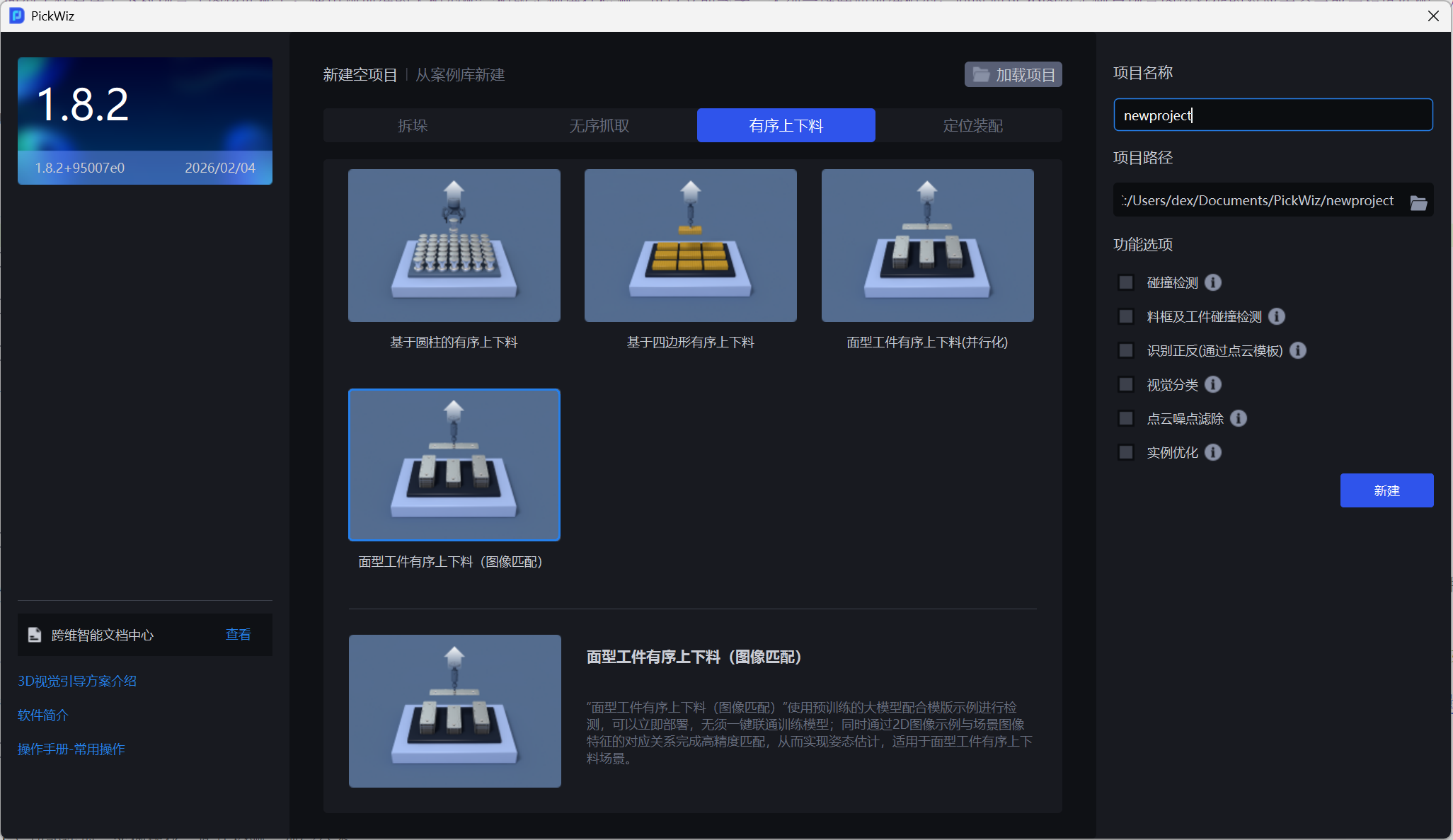
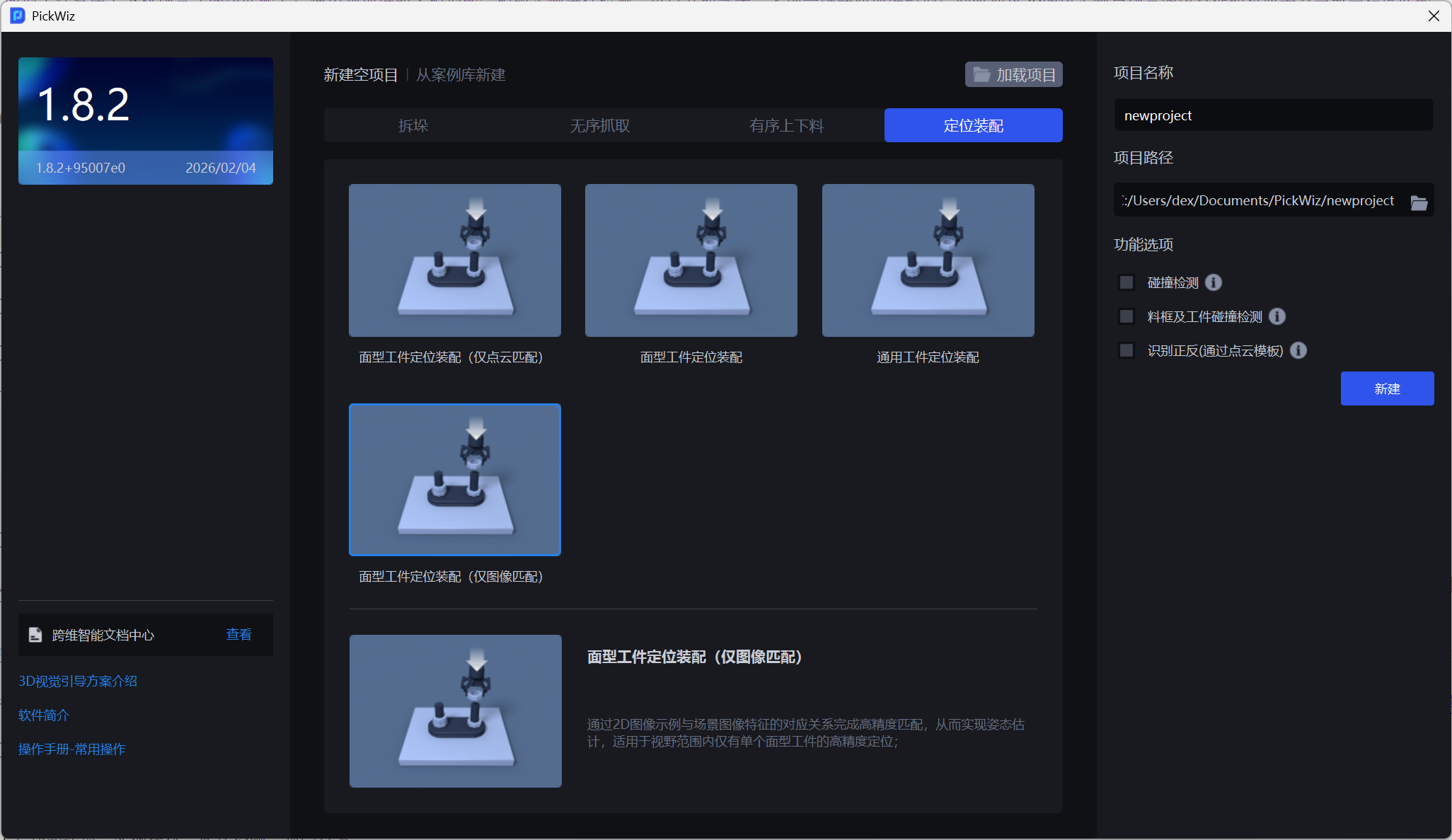
Optional function options include collision detection, material frame and target collision detection, visual classification, Point Cloud noise removal and Instance Optimization
(2) Camera and Robot configuration
(3) Add Target
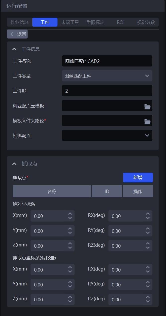
In the template folder in Target, you need to first create a Point Cloud template in the menu - Point Cloud Template Production. For details, see [Point Cloud Template Production] (#点云模板制作)
The template folder path is the template data generation path selected in Point Cloud template creation.
(4) Add End-effector, Eye-hand calibration, and ROI
Point Cloud Template Making
When the project type is "Loading and unloading of neatly arranged plane type target objects (image matching)" and "Plane type Target positioned assembly (image matching only)", you need to create a Point Cloud template in the "Menu" - "Point Cloud Template Production" function, "Historical Data Generation Template".
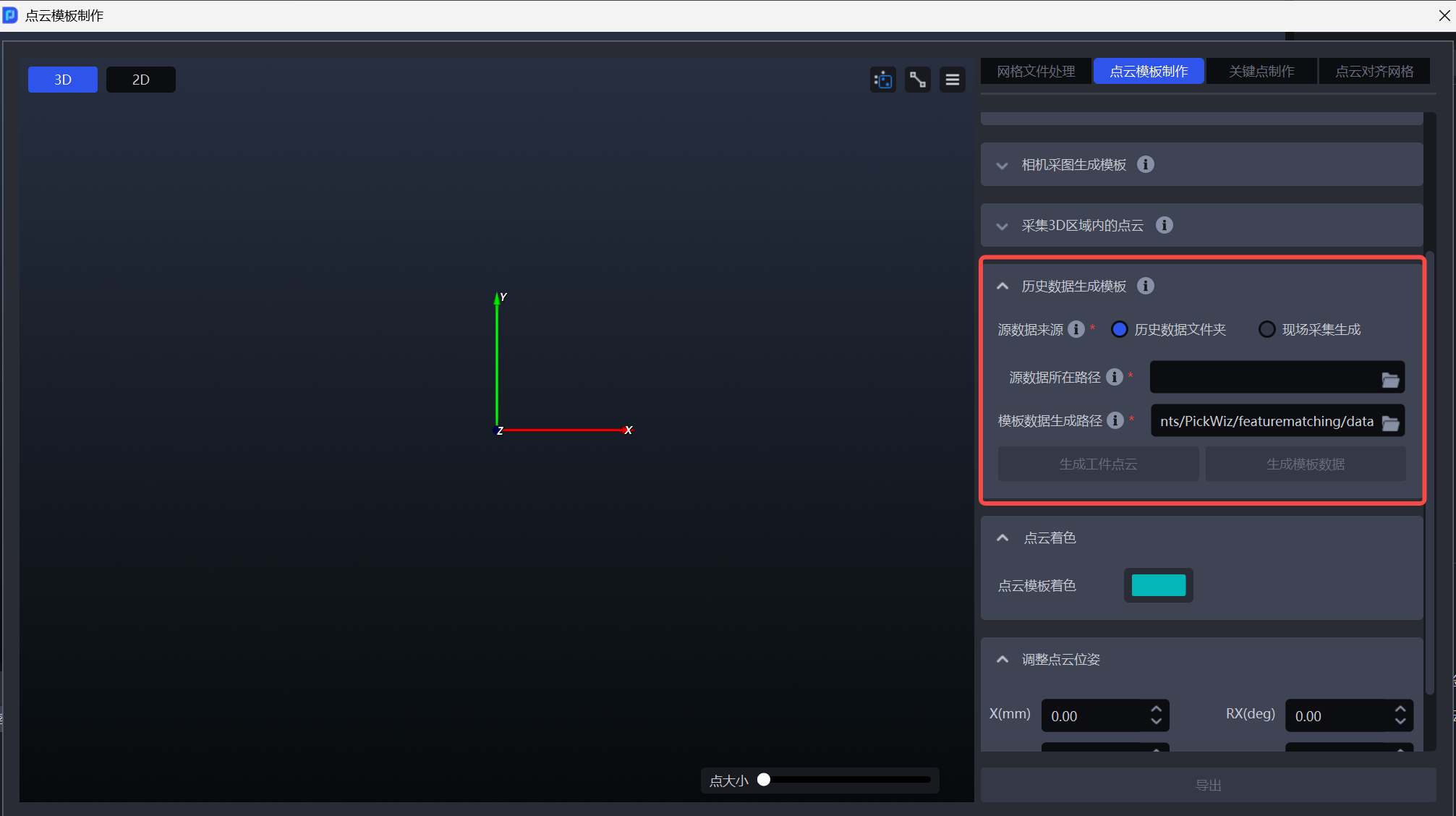
- Source data source: Historical data folder
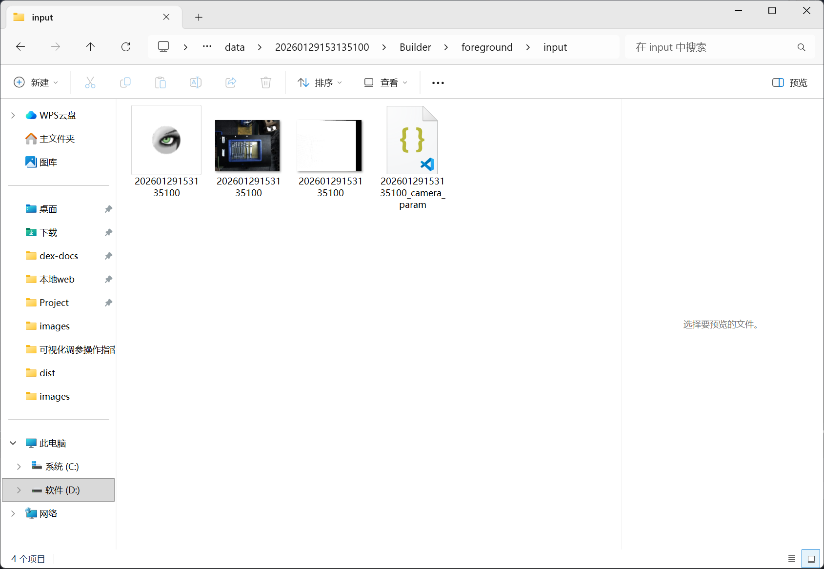
Source data path: select a complete historical data folder, usually in the project folder\data\PickLight\historical data\Builder\foreground\input
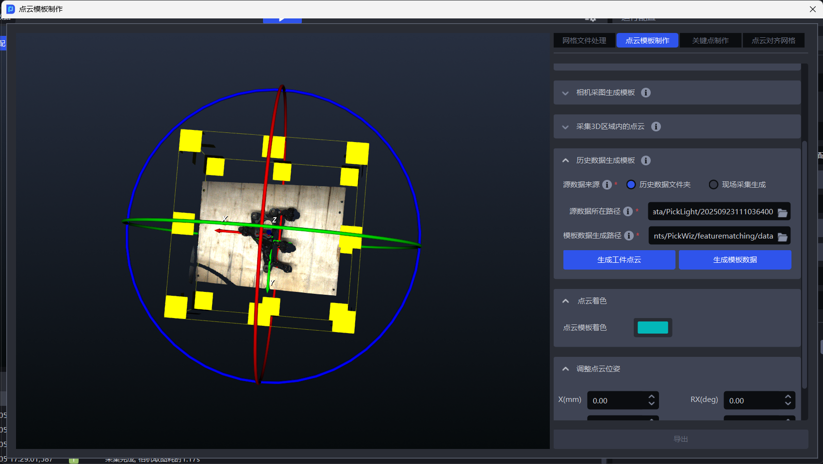
Template data generation path: By default, it is generated in the data folder of the current project and can be modified to other local folders.
Select the ROI area of the desired Target in the left window frame, click Generate TargetPoint Cloud, Point Cloud will appear in the left window, and edit the required TargetPoint Cloud through the Point Cloud editing tool in the upper right corner.
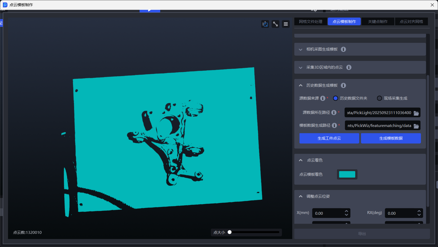
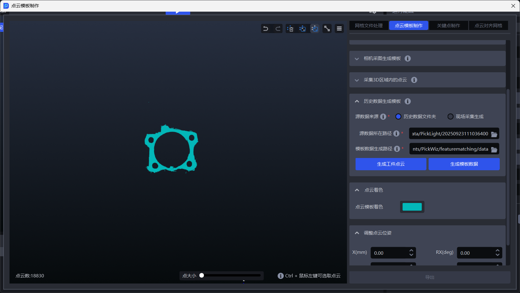
After TargetPoint Cloud is created, click Generate Template Data to complete the template generation.
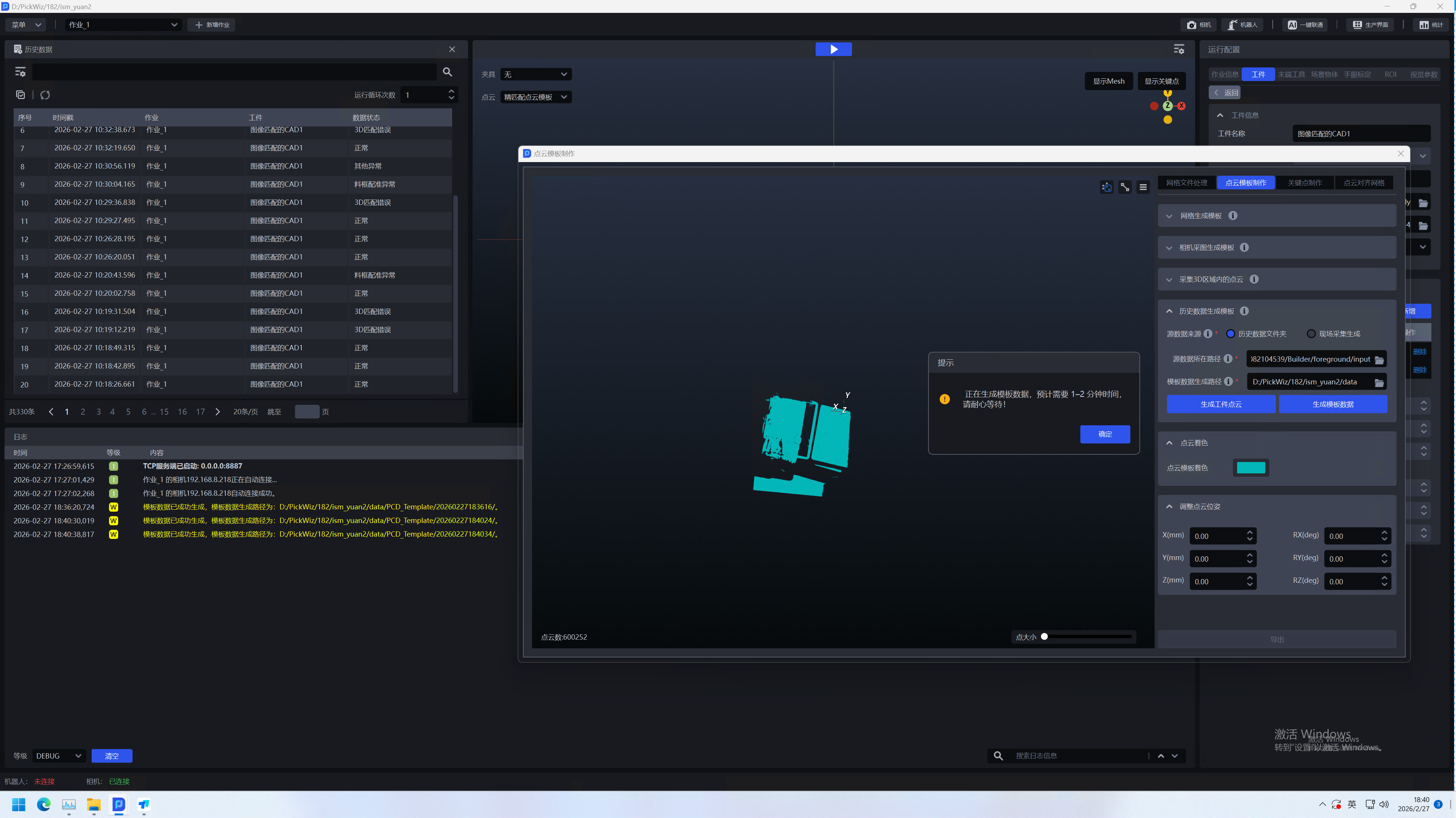
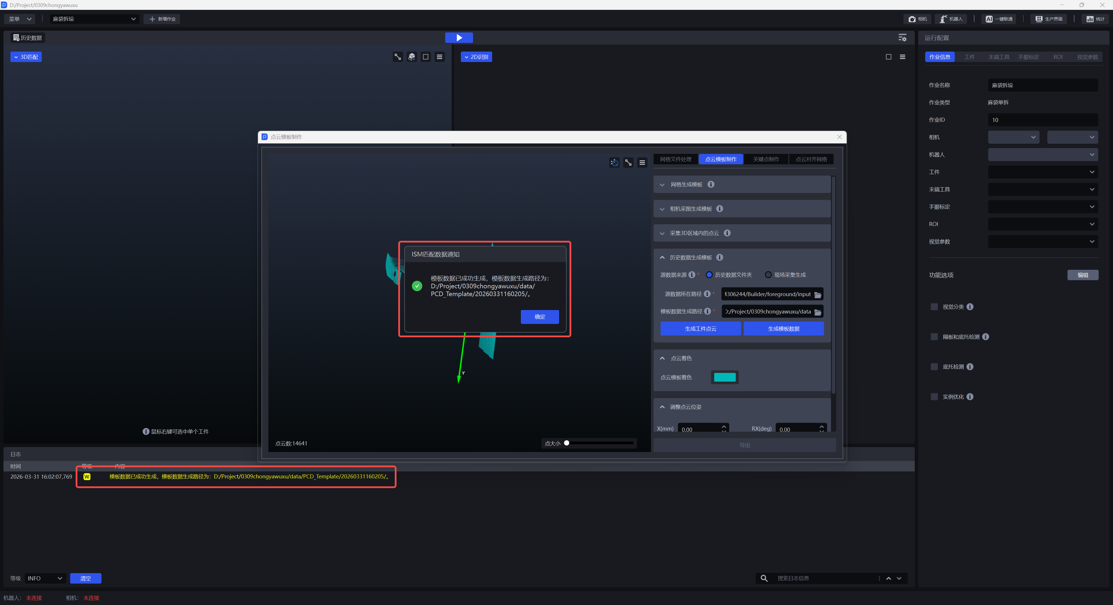
- Source data source: On-site collection and generation
Confirm that the Camera is connected and configure the Camera in the Task information, click Collect Image to generate the Point Cloud image, select the ROI of the Target location, click Generate TargetPoint Cloud, the Point Cloud will appear in the left window, edit the required TargetPoint Cloud through the Point Cloud editing tool in the upper right corner.
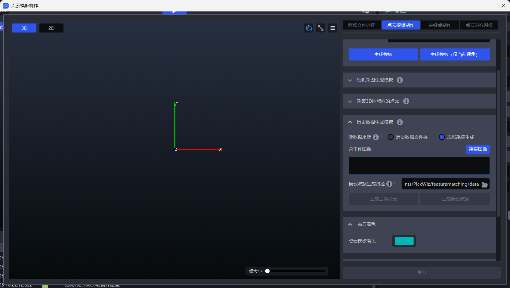
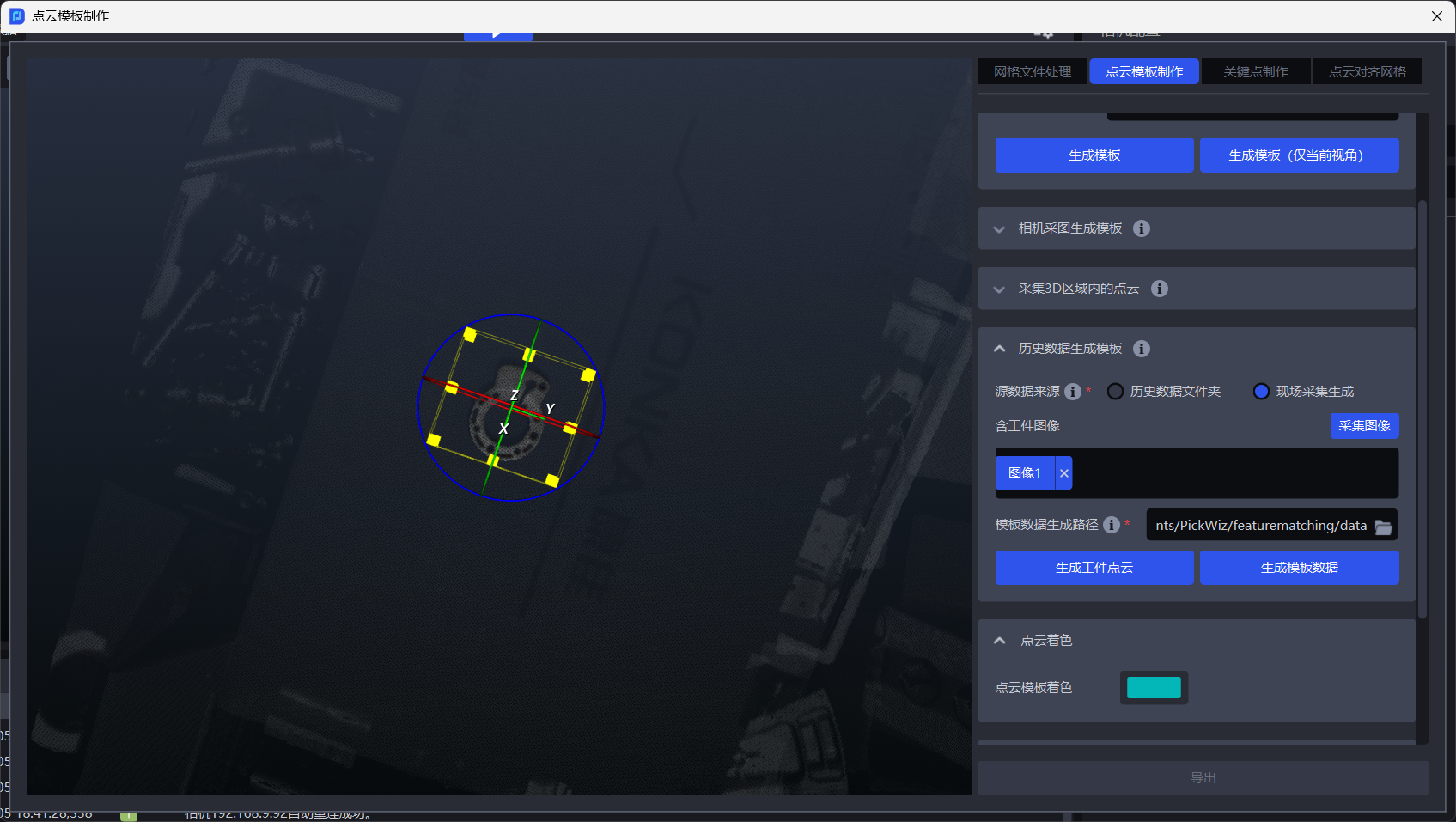
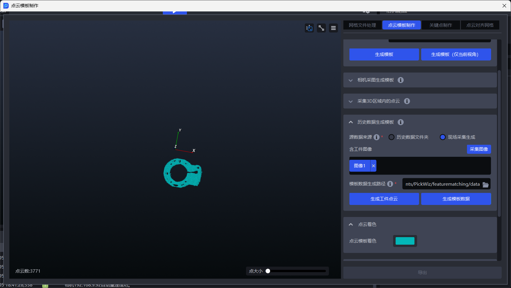
After TargetPoint Cloud is created, click Generate Template Data to complete the template creation.
After the Point Cloud template is generated, Pick Point needs to be adjusted to the Target center in the Target configuration. Changing the coordinate system to the Target center on meshlab will cause Task to report an error.
Visual Parameter
- 2D recognition: recognize and segment instances from the actual scene
Preprocessing: Process the 2D image before performing Instance Segmentation
Template-based Instance Segmentation: Identify segmented instances
Point Cloud generation: A way to generate an instance Point Cloud. Use a segmented instance mask or bounding box to generate an instance Point Cloud. Use a filtered instance mask or bounding box to generate an instance Point Cloud.
Instance filtering: Filter the split instances
Instance sorting: Sort the instances. The fetching order is the order in which the instances are sorted.
- 3D calculation: Calculate the posture of the instance in the Camera coordinate system and generate Pick Point
Preprocessing: Before calculating the Pick Point, preprocess the 3DPoint Cloud (calculate its own vertical posture, Point Cloud remove outliers)
Image matching pose estimation: calculate the pose of the instance in the Camera coordinate system (Coarse Matching, Fine matching) and generate Pick Point
Empty ROI judgment: judge whether there is a Target (Point Cloud) in the ROI 3D
- Pick Point processing: filter, adjust, and sort Pick Points
Pick Point filtering: Filter Pick Points
Pick Point adjustment: Adjust Pick Point
Pick Point Sorting: Sort Pick Points
2. 3D Computation
This section mainly explains the functions related to Pick Point generation and provides Parameter tuning recommendations.
2.1 Preprocessing
2.1.1 Cluster Filter
- Function
Remove noise by point cloud clustering
- Use Case
There is a large amount of noise in the instance point cloud
- Parameter Description
| Parameter Name | Description | Default Value | Range | Unit | Tuning Recommendation |
|---|---|---|---|---|---|
| Distance Threshold for Point Cloud Clustering (mm) | Determines whether point clouds in space belong to the same category. If the distance between point clouds is lower than this threshold, they are regarded as the same category. | 5 | [0.1, 1000] | mm | Generally does not need to be changed. It should be greater than the point spacing of the Target Object point cloud and smaller than the minimum distance between the Target Object point cloud and noise point clouds. |
| Minimum Point Count Threshold | Point cloud clusters with fewer points than this threshold are filtered out | 100 | [1,10000000] | / | Generally does not need to be changed. Increase the Minimum Point Count Threshold according to the amount of noise in the instance point cloud. |
| Maximum Point Count Threshold | Point cloud clusters with more points than this threshold are filtered out | 100000 | [1,10000000] | / | Generally does not need to be changed. If the number of points in the Target Object point cloud exceeds 100000, increase the Maximum Point Count Threshold. |
| Select Point Clouds at the Top of the ROI | If selected, the average Z coordinate of point clouds of the same category in the ROI coordinate system is computed and sorted, and the point cloud category with the largest average Z coordinate (top point cloud) is retained. If cleared, all point clouds that meet the conditions are retained. | Cleared | / | / | If the Target Object point cloud is above the noise point cloud, selecting this option retains the Target Object point cloud. If the Target Object point cloud is below the noise point cloud, this option should be selected while also adjusting the Z-axis of the ROI coordinate system to point downward so that the Target Object point cloud can be retained. |
| Visualize Process Data | If selected, the denoised point cloud is saved and can be viewed in C:_data | Cleared | / | / | This can be selected in debugging mode if you need to save visualization data. |
2.1.2 Point Cloud Downsampling
- Function
Sample the point cloud according to the specified point spacing to reduce the number of calculation points and improve model inference speed, though accuracy may decrease
- Use Case
When the number of point clouds in the actual scene is too large, select Point Cloud Downsampling.
- Parameter Description
| Parameter | Description | Default Value | Range | Unit |
|---|---|---|---|---|
| Point Spacing for Downsampling (mm) | Sample the point cloud according to the specified point spacing | 5.0 | [0.1, 1000] | mm |
Parameter Tuning
The larger the value of Point Spacing for Downsampling, the fewer the number of point clouds after downsampling, so Pick Point computation becomes faster, but accuracy may decrease
The smaller the value of Point Spacing for Downsampling, the greater the number of point clouds after downsampling, so Pick Point computation becomes slower, but accuracy improves
2.1.3 Calculate Vertical Pose
- Function
Compute the pose of a tilted sack in the vertical direction
- Use Case
Tilted sack placement in depalletizing scenarios
- Parameter Description
| Parameter | Description | Default Value | Range | Unit |
|---|---|---|---|---|
| Neighborhood Range | Neighborhood range of the center point on the sack surface, that is, the distance from the center point to the edge. This value affects the processing and analysis of the surrounding point cloud of the center point. | 20.00 | [0, 100] | / |
| Point Cloud Accuracy (mm) | Distance between adjacent points in the 3D point cloud image captured by the camera | 10 | [1, 1000] | mm |
| Use OBB for Computation | If selected, the z vector of the point cloud OBB (oriented bounding box) is used as the vertical direction of the sack itself. Otherwise, the point cloud within the neighborhood range of the center point is traversed, and the largest axis in the projection axes among these point clouds is selected as the vertical direction of the sack itself. | Cleared | / | / |
- Example
2.1.4 Filter by HSV
- Function
Filter point clouds according to hue, saturation, and brightness in the point cloud image, and screen out point cloud regions that match the target range
- Parameter Description
| Parameter Name | Description | Default Value | Range |
|---|---|---|---|
| Filter Depth by HSV - Maximum Color Range Value | Maximum color value for point cloud filtering | [0.9,0.9,0.9] | [[0,0,0],[1,1,1]] |
| Filter Depth by HSV - Minimum Color Range Value | Minimum color value for point cloud filtering | [0.0,0.0,0.0] | [[0,0,0],[1,1,1]] |
2.1.5 Filter by RGB
- Function
Filter point clouds by three-channel color and screen out point cloud regions that match the target range
- Parameter Description
| Parameter Name | Description | Default Value | Range |
|---|---|---|---|
| Filter Point Clouds by Three-Channel Color - Maximum Color Value | Maximum color value for point cloud filtering | [0.9,0.9,0.9] | [[0,0,0],[1,1,1]] |
| Filter Depth by Three-Channel Color - Minimum Color Value | Minimum color value for point cloud filtering | [0.0,0.0,0.0] | [[0,0,0],[1,1,1]] |
2.1.6 Extract PCD in ROI
- Function
Select point clouds within the ROI 3D area from the instance point cloud. This default function cannot be deleted.
2.1.7 Enhacne Mask Based on PCD
- Function
Based on the point cloud within ROI 3D, remove point clouds in the mask that are outside ROI 3D, thereby improving mask accuracy
- Use Case
Applicable to depalletizing scenarios where the model recognition result extends outside ROI 3D
2.1.8 Filter Pose by Normal Angle
- Function
Remove points whose angle between the normal vector and the standard normal vector axis is greater than the normal vector angle threshold
- Use Case
Loading and unloading of planar Target Objects (materials are isolated from each other)
- Parameter Description
| Parameter Name | Description | Default Value | Range | Unit |
|---|---|---|---|---|
| Angle Threshold | Point clouds whose angles are greater than this angle threshold are regarded as different instances | 15 | [-360, 360] | |
| Standard Normal Vector Axis Direction | The angle between the point cloud normal vector and the standard normal vector axis direction | Z-axis | X/Y/Z-axis | / |
| Whether to Use the ROI Coordinate System | If selected, the angle between the normal vector and the axes of the ROI coordinate system is computed. If cleared, the angle between the normal vector and the axes of the camera coordinate system is computed. | Cleared | / | / |
2.1.9 PCD Plane Segmentation
- Function
When fitting a plane to the point cloud, points whose distance to the plane is lower than the reference distance are regarded as points on the plane; otherwise, they are regarded as points outside the plane. The fitted plane can be retained or removed.
- Use Case
Applicable to single-carton depalletizing scenarios, but not applicable to single-sack depalletizing scenarios
- Parameter Description
Default Value: 3.000
Range: [0.001, 10000]
Unit: mm
- Parameter Tuning
The larger the reference distance, the thicker the fitted plane; the smaller the reference distance, the thinner the fitted plane
If Remove Plane is selected, the plane with the largest number of point clouds is removed. If it is cleared, the plane with the largest number of point clouds is retained.
- Example
2.1.10 Remove Statistical Outlier
- Function
Identify and remove outlier noise from the neighboring point region (that is, the neighborhood) of each point in the point cloud
- Use Case
The object point cloud contains many outlier noise points
- Parameter Description
| Parameter | Description | Default Value | Range | Tuning Recommendation |
|---|---|---|---|---|
| Reference Neighborhood Point Count | The number of adjacent points to each point in the point cloud, that is, the neighborhood size. For dense point clouds, even a small neighborhood is sufficient to reflect object features, so a smaller value can be used; for sparser point clouds, a larger neighborhood is required to reflect object features, so a larger value should be used. | 30 | [1, 10000000] | |
| Standard Deviation Multiplier | Used to identify outliers. If the deviation between a point's coordinates and the average coordinates of the object point cloud exceeds the standard deviation multiplier, the point is regarded as an outlier. The smaller the value, the more points are regarded as outliers and removed, but this may cause misjudgment and remove important object features. The larger the value, the fewer points are regarded as outliers and removed, but some outliers may be retained and affect image recognition accuracy. | 0.005 | [0.0001, 2] | If the point cloud becomes too sparse after Point Cloud Outlier Removal, you should increase the Standard Deviation Multiplier |
- Example
2.1.11 Remove PCD of Over-limit Distance
- Function
Filter out point clouds along the specified direction, remove noise points, and improve the accuracy of Pick Point computation
- Use Case
Usually used in single-sack depalletizing scenarios
- Parameter Description
| Parameter | Description | Default Value | Range | Unit | Tuning Recommendation |
|---|---|---|---|---|---|
| Specified Axis | Specified axis of the point cloud, used to filter out point clouds in the specified direction | Z-axis | X/Y/Z-axis | / | Specified Axis generally does not need to be changed |
| Threshold (mm) | Along the specified axis direction, if the distance between the lower-layer point cloud and the Target Object point cloud is greater than this threshold, the lower-layer point cloud is filtered out; if the distance between the lower-layer point cloud and the Target Object point cloud is less than this threshold, the lower-layer point cloud is retained. | 750 | [0, 1000] | mm | Adjust the Threshold according to the actual scene. The larger the Threshold, the fewer point clouds are filtered out; the smaller the Threshold, the more point clouds are filtered out. |
| Select Coordinate System | Filter out point clouds in the selected coordinate system | ROI Coordinate System | Camera Coordinate System; ROI Coordinate System; Object Self Coordinate System | / |
- Example
When the point cloud contains lower-layer point clouds, as shown in the left figure below, after Filter Out Point Clouds Whose Object Distance Exceeds the Limit is selected to remove the lower-layer point cloud, the resulting point cloud is shown in the right figure below
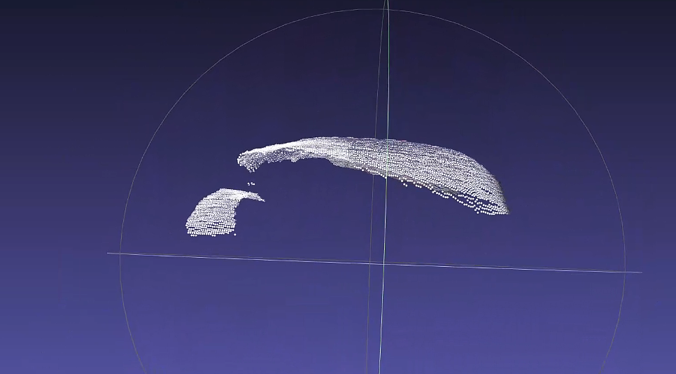
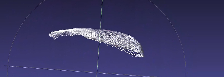
As shown below, comparing the effect when the threshold is 100 with the detection result when the threshold is 400, the larger the threshold, the fewer point clouds are filtered out.
2.2 Image matching pose estimation
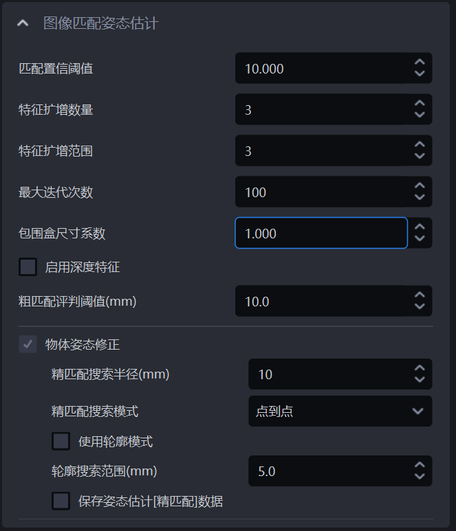
2.2.1 Match Confidence Threshold (mm)
- Function
The credibility score of feature point matching. The higher the score, the higher the quality of the feature points, but the fewer the number of matched feature points may be.
- Use Scene
Scene with more noise in feature detection
- Parameter description * *
Feature points below this Threshold will be deleted
- Adjust parameters
Default value: 0.01
Value range: [0.001, 1.0]
2.2.2 Number of feature amplifications
- Function
Amplify default features
- Use Scene
Scenes with few feature point detection results or key points mainly detected at the edges.
- Parameter description * *
Number of additional amplification points
- Adjust parameters
Try to reduce it to 0 when matching tilt or offset, and try to increase it to 5 when the key points are mainly detected at the edge.
2.2.3 feature amplification range
- Function
Adjust the pixel range of feature augmentation selection
- Use Scene
Key point detection matches scenes with large offsets between edge parts or templates and Scene key points.
- Parameter description * *
Take the original feature point as the center and select the amplification point within the area with the radius of the amplification range.
- Adjust parameters
No adjustment is recommended yet
2.2.4 Maximum number of iterations
- Function
Adjust the maximum number of matching iterations
- Adjust parameters
No adjustment is recommended yet
2.2.5 bounding box size coefficient
- Function
Adjust Scene instance image
- Use Scene
Scene when the Instance Segmentation mask is smaller than the Target or close to the Target
- Parameter description * *
The bounding box size scaling used when clipping Scene instances
- Adjust parameters
The feature points of the outer contour may be lost and need to be enlarged.
2.2.6 Enable depth features
- Adjust parameters
Adjustment is not supported yet
2.2.7 Coarse MatchingThreshold
- Function
Evaluate matching performance
- Use Scene
Used when matching skew or anomalies
- Parameter description * *
Matching point pairs smaller than the Threshold are considered valid
- Adjust parameters
It is recommended to adjust the adjustment smaller when matching the tilt of small objects, and it is recommended to increase the adjustment when matching the tilt of large objects.
2.2.9 object attitude correction
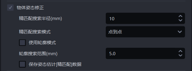
Fine matching search radius (mm)

- Function
In the fine matching process, the template Point Cloud is matched with the instance Point Cloud. Each point in the template Point Cloud needs to search for the nearest neighbor point in the instance Point Cloud. Fine matching search radius represents both the search radius in the instance Point Cloud and the distance Threshold between each point in the template Point Cloud and the nearest point in the instance Point Cloud. If the distance between a point and the nearest neighbor point is less than the Fine matching search radius, the two points are considered to be able to match, otherwise the two points are considered not to match.
- Use Scene
Plane type Target ordered loading and unloading, Picking of randomly arranged plane type target objects, Plane type Target positioned assemblyScene
- Parameter description * *
Default value: 10
Value range: [1, 500]
Unit: mm
- Adjust parameters
Usually not changed
Fine matching search mode

- Function
During the Fine matching process, the template Point Cloud retrieves the nearest point in the instance Point Cloud.
- Use Scene
The Fine matching effect between template Point Cloud and instance Point Cloud is not good, and this function should be adjusted.
- Parameter description * *
| Parameter | Description |
|---|---|
| point to point | Each point in the template Point Cloud searches for the nearest point in the instance Point Cloud (the point with the shortest straight line distance within the search radius). Applicable to all Targets |
| Point to point | Each point in the template Point Cloud searches for the nearest point in the instance Point Cloud along its normal vector. It is suitable for Targets with obvious geometric features. |
| Combination of point-to-point and point-to-surface methods | First use the point-to-point mode to optimize the Target posture in the instance Point Cloud, and then use the point-to-point mode to optimize the Target posture in the instance Point Cloud. It is suitable for Targets with obvious geometric features.
|
Use outline mode

- Function
Extract the contour Point Cloud in the template Point Cloud and instance Point Cloud for Coarse Matching
- Use Scene
Surface type Target ordered loading and unloading, Picking of randomly arranged plane type target objects, Plane type Target positioned assemblyScene, if the results of using key points for Coarse Matching are not good, you should check this function and use the contour Point Cloud to perform Coarse Matching again.
- Adjust parameters
The results of Coarse Matching will affect the results of Fine matching. If the results of Fine matching are not good, you can check Use outline mode
Contour search range (mm)

- Function
Extract the search radius of the contour Point Cloud in the template Point Cloud and the instance Point Cloud
- Use Scene
Loading and unloading of neatly arranged general type target objects、Picking randomly arranged general type target objects、General Target positioned assemblyScene
- Parameter description * *
Default value: 5
Value range: [0.1, 500]
Unit: mm
- Adjust parameters
If the value is smaller, the radius of the search contour Point Cloud is smaller, which is suitable for extracting detailed Target contours, but the extracted contours may contain outlier noise;
If the value is larger, the radius of the search contour Point Cloud is larger, which is suitable for extracting wider Target contours, but the extracted contours may ignore some detailed features.
Save pose estimation[Fine matching] data
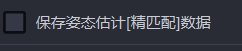
- Function
If checked, Fine matching data will be saved.
- Use Scene
Plane type Target ordered loading and unloading, Picking of randomly arranged plane type target objects, Plane type Target positioned assembly, Plane type Target positioned assembly (match only)
- Example
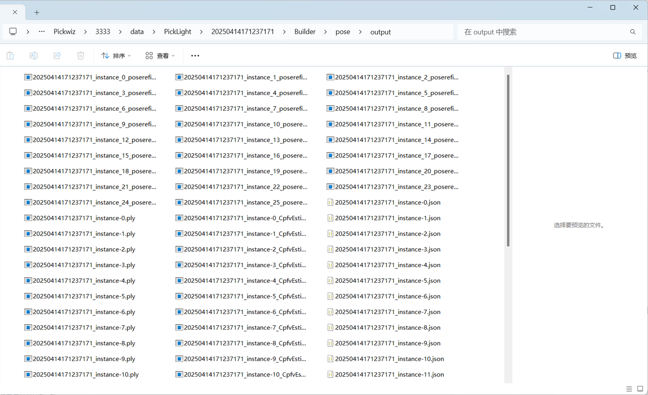
Fine matching data is saved in the project saving path \project folder\data\PickLight\historical data timestamp\Builder\pose\output folder.
3. Pick Point
This section mainly explains functions related to Pick Point filtering and adjustment, along with Parameter tuning recommendations.
3.1 Pick Point Adjustment
3.1.1 Bound Euler Angle
- Function description
When the Picking Pose is outside the configured angle range, it is rotated counterclockwise by a certain angle around a fixed axis. If it is still outside the configured angle range after rotation, a warning is issued.
- Usage scenario
This function is only applicable to depalletizing scenarios. It can keep the robot's approach direction stable during picking and prevent the end effector from repeatedly rotating during the picking process. In 180° cases, it can prevent exceptions such as cable twisting.
- Parameter description
| Parameter | Description | Default | Range | Unit |
|---|---|---|---|---|
| Fixed axis | An axis of the Picking Pose. The pose is rotated counterclockwise around this fixed axis | Z-axis | X/Y/Z-axis | / |
| Rotation angle | The angle by which the pose is rotated counterclockwise around the fixed axis. Adjust this angle so the Picking Pose satisfies the angle range | 0 | [-360,360] | degree |
| Angle range | The angle range of the Picking Pose. Set the angle range according to factors such as material placement, end effector type, and cycle time | [0,180] | [-180,180] | degree |
| Use current robot Euler Angles | By default, pose calculation uses Euler Angles "XYZ". When selected, the Euler Angles configured for the current robot are used so the pose remains consistent with the robot teach pendant. | Unchecked | / | / |
| Custom coordinate system | The coordinate system of the Picking Pose | Robot arm coordinate system | Default coordinate system; camera coordinate system; ROI coordinate system; robot arm coordinate system | / |
- Example
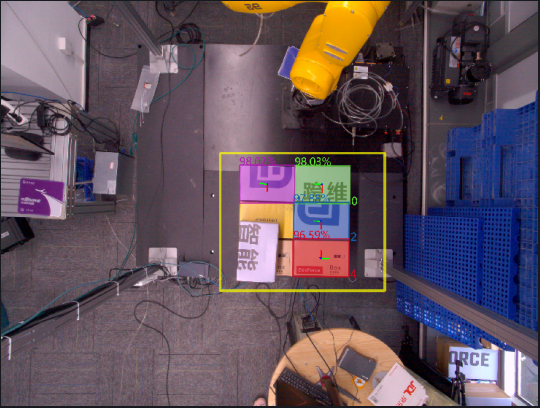
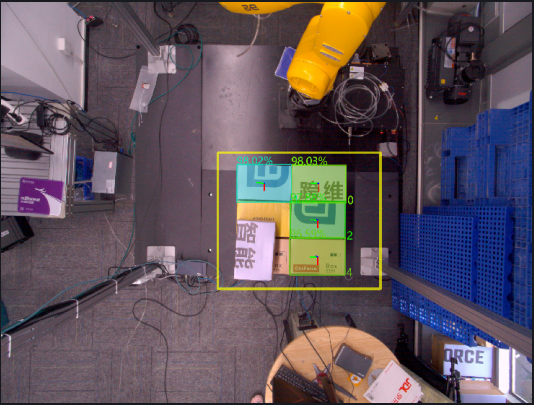
Without using this function, the generated Pick Points are shown below.
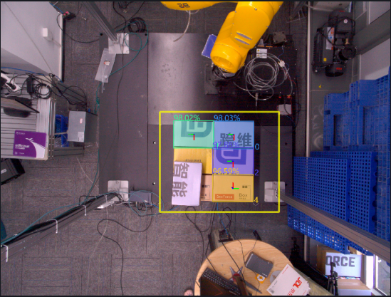
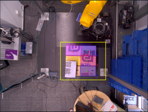
When this function is used with the default values, the RZ angles of the Picking Poses for instances 0, 1, and 2 are all within the angle range [0,180], so no processing is performed. The RZ angle of the Picking Pose for instance 4 is -90°, which is outside the angle range [0,180], so the Picking Pose of instance 4 is rotated by 0° around the fixed Z-axis.
If you want to adjust the RZ angle of the Picking Pose for instance 4 into the angle range, you can change the rotation angle to 180 and rotate the Picking Pose of instance 4 by 180° around the fixed Z-axis.
3.1.2 Rotate the pose to align the rotation axis direction with the target axis direction
- Function description
Rotate the Picking Pose once around the fixed axis so that the direction of the rotation axis (determined by the right-hand rule) matches the positive or negative direction of the target axis in the target coordinate system.
- Usage scenario
Avoid collisions between the robot end effector and the bin.
- Parameter description
| Parameter | Description | Default | Range |
|---|---|---|---|
| Rotation axis | An axis of the Picking Pose. Determined by the right-hand rule, the Picking Pose is rotated counterclockwise once around the fixed axis so that the direction of the rotation axis matches the positive or negative direction of the target axis in the target coordinate system | X-axis | X/Y/Z-axis |
| Fixed axis | The Picking Pose is rotated counterclockwise once around the fixed axis so that the direction of the rotation axis matches the positive or negative direction of the target axis in the target coordinate system | Z-axis | X/Y/Z-axis |
| Target axis | An axis of the target coordinate system. The Picking Pose is rotated counterclockwise once around the fixed axis so that the direction of the rotation axis matches the positive or negative direction of the target axis in the target coordinate system | X-axis | X/Y/Z-axis |
| Negative target axis direction | If selected, the direction of the rotation axis is aligned with the negative direction of the target axis in the target coordinate system; otherwise, it is aligned with the positive direction of the target axis in the target coordinate system | Unchecked | / |
| Custom coordinate system | The coordinate system of the Picking Pose | Default coordinate system | Default coordinate system; camera coordinate system; ROI coordinate system; robot arm coordinate system |
3.1.3 Rotate Pose to Align Axis
- Function description
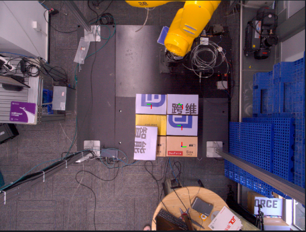
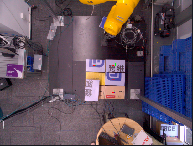
Rotate the Picking Pose around the fixed axis by 0, 90, 180, and 270 degrees respectively, calculate the angle between the rotated rotation axis and the positive or negative direction of the target axis in the camera coordinate system, and finally output the Picking Pose with the smallest angle after rotation.
- Usage scenario
Avoid collisions between the robot end effector and the bin.
- Parameter description
| Parameter | Description | Default | Range |
|---|---|---|---|
| Fixed axis | An axis of the Picking Pose. Rotate the pose counterclockwise around this fixed axis | Z-axis | X/Y/Z-axis |
| Rotation axis | An axis of the Picking Pose. When rotating the pose, calculate the angle between this rotation axis and the positive or negative direction of the target axis | X-axis | X/Y/Z-axis |
| Target axis | An axis of the camera coordinate system. When rotating the pose, calculate the angle between the rotation axis and the positive or negative direction of this target axis | X-axis | X/Y/Z-axis |
| Negative target axis direction | If selected, calculate the angle between the rotation axis and the negative direction of the target axis; otherwise, calculate the angle between the rotation axis and the positive direction of the target axis | Selected | / |
| Custom coordinate system | The coordinate system of the Picking Pose | Default coordinate system | Default coordinate system; camera coordinate system; ROI coordinate system; robot arm coordinate system |
- Example
3.1.4 Flip Pose to Align Axis
- Function description
Rotate the Picking Pose once around the fixed axis so that the angle formed between the rotation axis and the positive or negative direction of the target axis in the ROI coordinate system is acute.
- Usage scenario
Avoid collisions between the robot end effector and the bin.
- Parameter description
| Parameter | Description | Default | Range |
|---|---|---|---|
| Fixed axis | An axis of the Picking Pose. Rotate the Picking Pose counterclockwise around this fixed axis | Z-axis | X/Y/Z-axis |
| Rotation axis | An axis of the Picking Pose. Rotate the Picking Pose so that the direction of this rotation axis matches the positive or negative direction of the target axis | X-axis | X/Y/Z-axis |
| Target axis | An axis in the ROI coordinate system. Rotate the Picking Pose so that the direction of the rotation axis matches the positive or negative direction of this target axis | X-axis | X/Y/Z-axis |
| Negative target axis direction | If selected, rotate the Picking Pose so that the direction of the rotation axis matches the negative direction of the target axis; otherwise, rotate the Picking Pose so that the direction of the rotation axis matches the positive direction of the target axis | Selected | / |
| Custom coordinate system | The coordinate system of the Picking Pose | Default coordinate system | Default coordinate system; camera coordinate system; ROI coordinate system; robot arm coordinate system |
- Example
3.1.5 Flip Axis to ROI Center
- Function
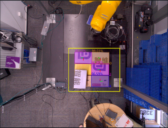
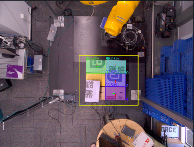
Rotate the Picking Pose around a fixed axis so that the pointing axis of the Picking Pose points to the ROI center.
- Usage scenario
Avoid collisions between the robot end effector and the bin.
- Parameter description
| Parameter | Description | Default | Range |
|---|---|---|---|
| Pointing axis | The axis in the Picking Pose that needs to be adjusted | X-axis | X/Y/Z-axis |
| Fixed axis | The axis that remains unchanged during rotation | Z-axis | X/Y/Z-axis |
| Reverse align | If selected, reverse-align the pointing axis to the ROI center; otherwise, align the pointing axis to the ROI center | Selected | / |
| Strict pointing | If selected, force the Picking Pose to rotate so the pointing axis points to the ROI center | Unchecked | / |
| Custom coordinate system | The coordinate system of the Picking Pose | Default coordinate system | Default coordinate system; camera coordinate system; ROI coordinate system; robot arm coordinate system |
- Example
3.1.6 Transform to Target Pose
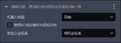
- Function description
Rotate the Picking Pose so that its Z-axis direction matches the Z-axis of the target coordinate system.
- Usage scenario
Usually this is used by default only in depalletizing scenarios and cannot be deleted. It is used to make the Z-axis of the Picking Pose perpendicular to the Z-axis of the ROI coordinate system (4-axis) or consistent with the direction of the Target Object surface (6-axis).
- Parameter description
| Parameter | Description | Default | Range |
|---|---|---|---|
| Robot configuration | Set according to the on-site robot configuration. You can choose 4-axis or 6-axis. If a 6-axis robot is actually used as a 4-axis robot, it should be set to 4-axis | 4-axis | 4-axis/6-axis |
| Use ROI Z-axis as target direction | When the robot configuration is set to 4-axis, if selected, the pose is rotated around the X-axis so that the Z-axis direction of the rotated pose matches the positive direction of the ROI Z-axis ; if not selected, the pose is rotated around the X-axis so that the Z-axis direction of the rotated pose matches the positive direction of the Z-axis of the camera coordinate system . When the robot configuration is set to 6-axis, regardless of whether it is selected, the pose is rotated around the X-axis so that the Z-axis direction of the rotated pose matches the positive direction of the Z-axis of the object's own coordinate system | Unchecked | / |
| Custom coordinate system | The coordinate system of the Picking Pose | Camera coordinate system | Default coordinate system; camera coordinate system; ROI coordinate system; robot arm coordinate system |
- Example
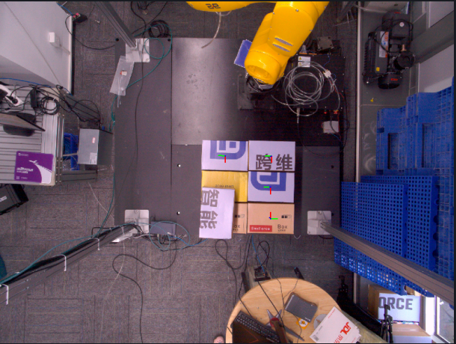
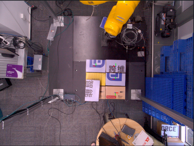
3.1.7 Rotate Pose with Angle
- Function description
Rotate the Picking Pose by a certain angle around a fixed axis.
- Usage scenario
Avoid collisions between the robot end effector and the bin.
- Parameter description
| Parameter | Description | Default | Range | Unit |
|---|---|---|---|---|
| Rotation angle | The angle by which the pose is rotated counterclockwise around the fixed axis | 90 | [-360, 360] | degree° |
| Fixed axis | An axis of the Picking Pose. Rotate the pose counterclockwise around this fixed axis | Z-axis | X/Y/Z-axis | / |
| Custom coordinate system | The coordinate system of the Picking Pose | Default coordinate system | Default coordinate system; camera coordinate system; ROI coordinate system; robot arm coordinate system | / |
- Example
3.1.8 Move Pose With Offset
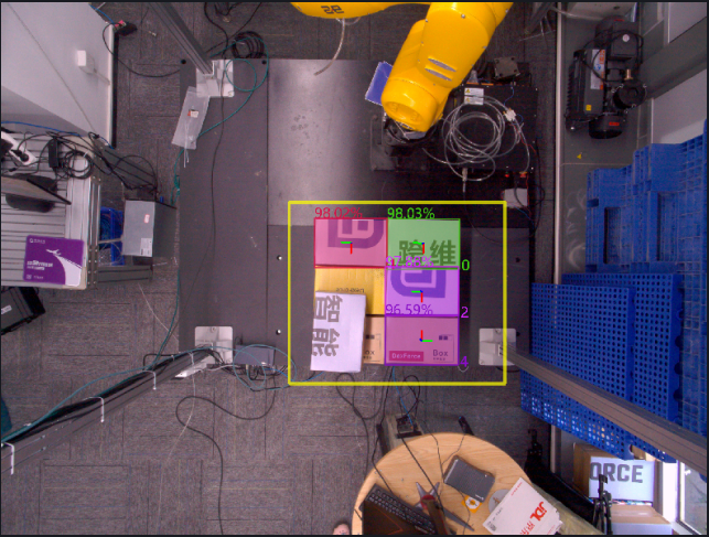
- Function description
Move the Picking Pose by a certain distance along the translation axis.
- Usage scenario
Avoid collisions between the robot end effector and the bin.
- Parameter description
| Parameter | Description | Default | Range | Unit |
|---|---|---|---|---|
| Translation amount (mm) | The distance the Picking Pose moves along the translation axis. A positive translation amount means translating in the positive direction of the translation axis, and a negative translation amount means translating in the negative direction of the translation axis | 0 | [-1000, 1000] | mm |
| Translation axis | The direction in which the Picking Pose moves | X-axis | X/Y/Z-axis | / |
| Custom coordinate system | The coordinate system of the Picking Pose | Robot arm coordinate system | Default coordinate system; camera coordinate system; ROI coordinate system; robot arm coordinate system | / |
- Example
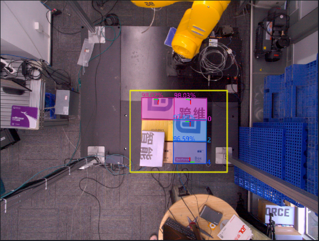
3.1.9 Transform Pose by Difference
- Function description
Record the Pick Point coordinates generated by the software and the Pick Point coordinates taught under the current operating condition, then output the transformed Picking Pose based on the offset between the two.
- Usage scenario
When the Pick Points generated by the vision system have an obvious systematic offset and the robot TCP coordinate accuracy is limited or difficult to calibrate, this method can be used to directly map the same offset pattern to subsequent Pick Points, thereby avoiding robot TCP calibration.
- Parameter description
| Parameter | Description | Default | Range |
|---|---|---|---|
| Vision Pose | Pick coordinates of the detection result | ||
| X(mm) | X coordinate of the Vision Pose | 0.00 | ±10000000, meaning no limit. |
| Y(mm) | Y coordinate of the Vision Pose | 0.00 | ±10000000, meaning no limit. |
| Z(mm) | Z coordinate of the Vision Pose | 0.00 | ±10000000, meaning no limit. |
| RX(°) | X-axis rotation amount of the Vision Pose | 0.00 | ±180 |
| RY(°) | Y-axis rotation amount of the Vision Pose | 0.00 | ±180 |
| RZ(°) | Z-axis rotation amount of the Vision Pose | 0.00 | ±180 |
| Picking Pose | Manually taught Pick Point | ||
| X(mm) | X coordinate of the Picking Pose | 0.00 | ±10000000, meaning no limit. |
| Y(mm) | Y coordinate of the Picking Pose | 0.00 | ±10000000, meaning no limit. |
| Z(mm) | Z coordinate of the Picking Pose | 0.00 | ±10000000, meaning no limit. |
| RX(°) | X-axis rotation amount of the Picking Pose | 0.00 | ±180 |
| RY(°) | Y-axis rotation amount of the Picking Pose | 0.00 | ±180 |
| RZ(°) | Z-axis rotation amount of the Picking Pose | 0.00 | ±180 |
3.1.10 Refine Pose by Plane Normal
- Function description
Correct the Object Pose by fitting the plane Normal so that the Z-axis direction of the Object Pose remains consistent with the direction of the plane Normal of the Target Object.
- Usage scenario
When the Target Object contains a plane and there is a tilt deviation in the plane when the template Point Cloud is matched with the actual Point Cloud, use this function to fine-tune the Target Object plane and improve picking accuracy.
Not applicable to depalletizing scenarios
- Parameter description
| Parameter | Description | Default | Range | Unit |
|---|---|---|---|---|
| Distance Threshold | Distance Threshold for fitting a plane from the Point Cloud | 10 | [-1000, 1000] | mm |
| Save visualization data | If selected, the visualization data will be saved under the historical data timestamp | Selected | / | / |
| Custom coordinate system | The coordinate system of the Picking Pose | Camera coordinate system | Default coordinate system; camera coordinate system; ROI coordinate system; robot arm coordinate system | / |
- Example
3.1.11 Sort Pick Points by Angle with ROI Axis
- Function
Sort Pick Points according to the angle between an axis of the Picking Pose and the target axis of the ROI.
- Parameter description
| Parameter | Description | Default | Range |
|---|---|---|---|
| Axis selection | An axis of the Picking Pose | Z-axis | X/Y/Z-axis |
| Target axis selection | An axis of the ROI coordinate system | Z-axis | X/Y/Z-axis |
| Select reverse direction | If selected, calculate the angle with the negative direction of the target axis; otherwise, calculate the angle with the positive direction of the target axis | Unchecked | / |
| Select descending order | If selected, sort Pick Points from small to large by angle; otherwise, sort Pick Points from large to small by angle | Unchecked | / |
3.1.12 [Advanced] Rotate Pose, Automatically Compensate for Grasp Orientation Angles with Excessive Deviation from the Specified Axis
- Function description
Determine whether the angle formed between the specified axis of the Picking Pose and the target axis is within the specified range. If not, adjust the Picking Pose into the specified range.
- Usage scenario
Avoid collisions between the robot end effector and the bin.
- Parameter description
| Parameter | Description | Default | Range | Unit |
|---|---|---|---|---|
| Angle range | Adjust the Picking Pose into the angle range | 30 | [0, 180] | degree° |
| Specified axis | An axis of the Picking Pose. Adjust this axis so that it falls within the angle range relative to the target axis of the ROI coordinate system | Z-axis | X/Y/Z-axis | / |
| Target axis | An axis of the ROI coordinate system. Compare the angle range with the specified axis of the Picking Pose | Z-axis | X/Y/Z-axis | / |
| Compare with the negative half-axis of the ROI | If not selected, compare the angle range with the positive direction of the target axis of the ROI coordinate system; if selected, compare the angle range with the negative direction of the target axis of the ROI coordinate system | Unchecked | / | / |
| Custom coordinate system | The coordinate system of the Picking Pose | Default coordinate system | Default coordinate system; camera coordinate system; ROI coordinate system; robot arm coordinate system | / |
3.1.13 [Advanced] Symmetry Center Pose Optimization
- Function
Search for the symmetry center of the Target Object based on the instance Mask, then combine it with the plane of the instance or the pose of the ROI 3D center point to calculate the optimal Picking Pose.
Before using this function, first make sure the instance Mask is symmetrical
- Usage scenario
Applicable when the instance Mask of a symmetrical Target Object is also symmetrical, but the Picking Pose is not near the expected center; at the same time, the Target Object has a plane that can be used as a reference, for example, there is a plane on the top of the object, or ROI 3D can be used as a reference for the projected pose.
Applicable project scenarios include brake discs (general circles), refractory bricks (depalletizing), symmetrical irregular parts, fuel fillers, and so on.
- Parameter description
| Parameter | Description | Default | Range | Tuning recommendation |
|---|---|---|---|---|
| Target Object Symmetry type | Target Object Symmetry type of the instance Mask | Rotational symmetry | Rotational symmetry: after the Target Object rotates by a certain angle around the center point, its shape completely overlaps with the original position; mirror symmetry: the Target Object uses a certain axis / plane as the mirror, and the left-right or upper-lower sides are completely symmetrical. | Circles and rectangles are both rotationally symmetrical and mirror-symmetrical, so rotational symmetry is preferred; for trapezoids and other shapes that are symmetrical only along a certain axis or plane, choose mirror symmetry. |
| Gaussian blur level | Tolerance for determining whether the actual Point Cloud overlaps after rotation | 3 | \[1,99\] |
|
| Rotation angle setting | When the symmetry mode is rotational symmetry, it indicates the rotation angle interval, that is, the angle difference between two adjacent rotations. When the symmetry mode is mirror symmetry, it indicates the rotation range, that is, the angle interval within which the Point Cloud can rotate around the symmetry axis. | 180 | \[1,360\] |
|
| Image scaling ratio | Adjusts the size of the Point Cloud image. The larger this ratio, the smaller the Point Cloud image size and the lower the GPU memory usage, but image detail loss increases, resulting in reduced calculation accuracy . | 2 | \[1,10000000\] | |
| Search range | Based on the initially determined center of the Target Object, this defines the range expanded outward to search for Point Cloud features. The actual range is (search range*2*image scaling ratio) | 10 | \[1,10000000\] | For example, for a square Target Object, the initially determined center position of the Target Object is point O. If the search range is set to 10 and the image scaling ratio is 1, then the actual search range is a square region centered at point O with a side length of 10×2×1=20. Point Cloud features are searched within this region to further determine the symmetry center of the Target Object and the optimal Picking Pose. As another example, for a circular Target Object, if the search range is set to 8 and the image scaling ratio is 2, then the actual search range is a circular region centered at the initially determined center of the Target Object with a diameter of 8×2×2=32. Point Cloud features are searched within this region to further determine the Object Pose of the Target Object and the optimal Picking Pose. |
| Use ROI3D as the reference projection plane | If selected, ROI3D is used as the reference projection plane | Unchecked | / | Select this when the Point Cloud has no obvious plane and the projection plane is difficult to determine; leave it unchecked when the Point Cloud has a clear plane. |
| Save symmetry center process data | If selected, the debug data generated during the symmetry center process is saved. You can view it in the `\ProjectName`\data`\PickLight`\HistoricalDataTimestamp`\find`\_symmetry_center folder | Unchecked | / | Select this when you need to inspect the detailed process images |
| Symmetry axis prior type | Effective in ``{=html}mirror symmetry``{=html} mode. Specifies the known Target Object Symmetry type and fixes the asymmetric orientation | Automatic search | Automatic searchSymmetric along the long axisSymmetric along the short axis | If the symmetry axis of the Target Object is the long axis, choose "Symmetric along the long axis". If the symmetry axis of the Target Object is the short axis, choose "Symmetric along the short axis". If uncertain, choose "Automatic search" |
| Pose adjustment type | Whether to inherit pose-related information from the input pose | Default pose | Default poseInherit rotationInherit translation | / |
| Symmetry score Threshold | Symmetry results with a symmetry score lower than this Threshold are abnormal results. When set to 0, no filtering is performed | 0.0 | \[0.0, 1.0\] | / |
- Example
3.2 Pick Point Filtering
3.2.1 Filter by Fine Matching Score
- Function description
Filter Pick Points based on the pose fine matching score.
- Parameter description
| Parameter | Description | Default | Range |
|---|---|---|---|
| Score Threshold | Retain Pick Points whose fine matching score is greater than this Threshold | 0.5 | [0, 1] |
3.2.2 Filter grasp points of occluded artifacts
- Function description
Determine whether there are too many occluding object Point Clouds in the target detection area along the specified ROI axis or the Picking Pose axis at the Pick Point of the grasped Target Object. If so, the Target Object is considered occluded and the Pick Point is filtered out.
- Usage scenario
Applicable to depalletizing and ordered scenarios in which Target Objects are picked layer by layer, but the model recognizes lower-layer Target Objects. When picking a lower-layer Target Object, the gripper may collide with the upper-layer Target Object.
- Parameter description
| Parameter | Description | Default | Range | Unit |
|---|---|---|---|---|
| Cuboid length in X direction | Set the cuboid length in the X direction of the Picking Pose | 1500 | [1, 10000] | mm |
| Cuboid length in Y direction | Set the cuboid length in the Y direction of the Picking Pose | 1500 | [1, 10000] | mm |
| Cuboid length in Z direction | Set the cuboid length in the Z direction of the Picking Pose | 800 | [1, 10000] | mm |
| Distance Threshold between detection area and Pick Point origin | Along the ROI axis, the nearby cuboid surface area farther than this distance Threshold from the Pick Point origin is regarded as the target detection area | 50 | [1, 1000] | mm |
| Point Cloud count Threshold in detection area | If the number of occluding object Point Clouds in the target detection area exceeds this Threshold, the Pick Point is considered occluded | 1000 | [0, 100000] | / |
| Specified axis direction | Based on the pose reference specified axis direction, set the specific location of the target detection area within the cuboid space (for example, near the front/back/left/right/top/bottom surface of the cuboid) | [0,0,-1] | [1,0,0]: positive X-axis[-1,0,0]: negative X-axis[0,1,0]: positive Y-axis[0,-1,0]: negative Y-axis[0,0,1]: positive Z-axis[0,0,-1]: negative Z-axis | / |
| Use ROI 3D pose reference | If selected, adjust the collision detection area according to the ROI 3D pose reference | Unchecked | / | / |
| Save visualization data | If selected, the visualization data is stored according to the saved data path to help observe whether the generated cuboid is reasonable; if not selected, it is not saved | Unchecked | / | / |
3.2.3 Filter Pose by Cone
- Function description
Determine whether the angle of the Picking Pose is within the constrained angle range, and filter out all Pick Points that do not meet the condition.
- Usage scenario
Prevent collisions caused by abnormal robot arm Picking Pose angles.
- Parameter description
| Parameter | Description | Default | Range | Unit |
|---|---|---|---|---|
| Angle filtering Threshold | Calculate the maximum angle between the specified axis of the ROI and the specified axis of the Picking Pose. Pick Points whose angle is greater than the current Threshold will be filtered out | 30 | [-360, 360] | degree° |
| Invert ROI specified axis direction | If selected, use the negative direction of the specified ROI axis for angle calculation; otherwise, use the positive direction of the specified ROI axis for angle calculation | Selected | / | / |
| Specified Picking Pose axis | Specify an axis of the Picking Pose for angle calculation | Z-axis | X/Y/Z-axis | / |
| Specified ROI axis | Specify an axis of the ROI coordinate system for angle calculation | Z-axis | X/Y/Z-axis | / |
3.2.4 Filter Pick Points outside the ROI 3D type area
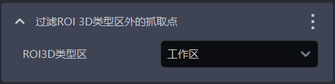
- Function description
Determine whether the Pick Point is within the ROI 3D range, and remove Pick Points that are outside the ROI 3D area.
- Usage scenario
Prevent picking outside the ROI area, which may cause collisions between the robot arm and the target object.
- Parameter description
| Parameter | Description | Default |
|---|---|---|
| ROI3D type region | Usually "workspace"; "pick area" is a smaller ROI region than "workspace", which can restrict Pick Points to an ROI region smaller than the "workspace" to avoid some collision cases. | Workspace |
- Example
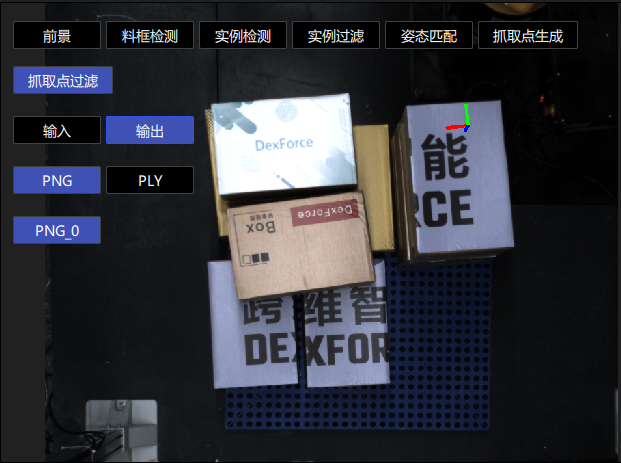
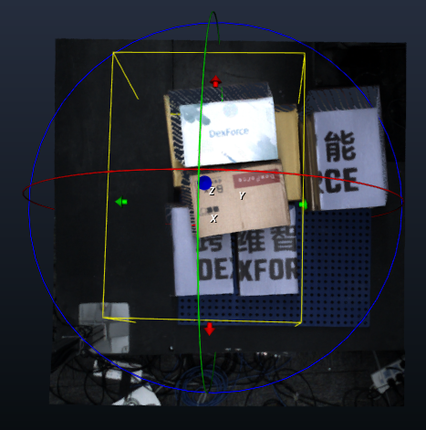
As shown in the figure below, when the ROI3D area and ROI2D are area a, the corresponding Pick Point is in the upper-right corner.
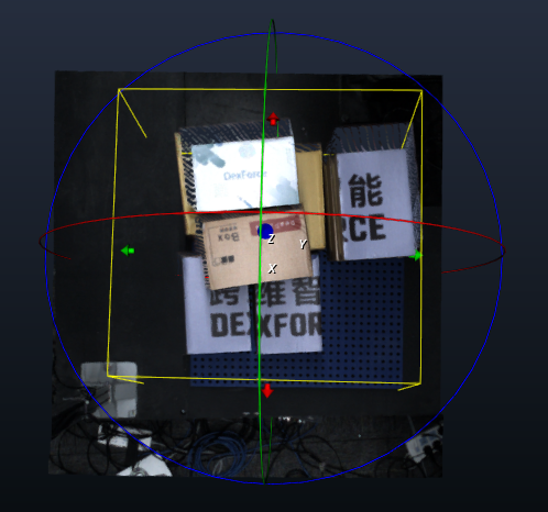
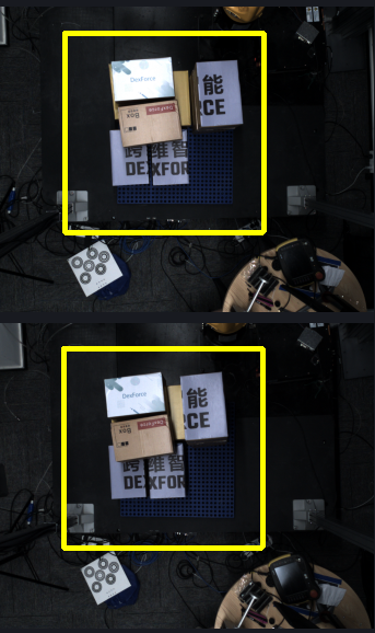
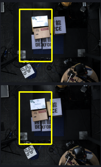
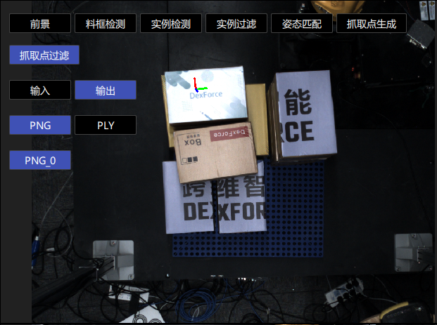
When the ROI3D area and ROI2D are changed to area b, the original Pick Point is outside the ROI area, so that Pick Point is removed and a new Pick Point is generated within area b.
3.2.5 [New] Gripper Collision Detection
[New] Gripper Collision Detection
- Function description
Collision detection between the gripper and the Point Cloud near the Pick Point. If the number of Point Clouds in contact with the gripper exceeds the pick collision Threshold, the Pick Point of the Target Object is considered to have a collision risk.
- Usage scenario
Used when collision detection is required between the gripper and the Point Cloud near the Target Object being picked.
- Parameter description
| Parameter | Description | Default | Range |
|---|---|---|---|
| Collision Threshold | Collision distance Threshold. If the distance between the scene and the gripper surface is smaller than this Threshold, it is considered a collision. The larger the Threshold, the stricter it is. Unit: mm | 7 | 1-1000 |
| Collision Point Cloud sampling | Sampling size for collision Point Clouds. The larger the value, the faster the cycle time; the smaller the value, the slower the cycle time. Effective only in "Target Object scene Point Cloud only" and "bin + Target Object scene Point Cloud" modes. Unit: mm | 5 | 1 - 1000 |
| Save visualization data for gripper collision detection | Save visualization data for collision detection between the gripper and the picked Target Object | Unchecked | Selected/Unchecked |
Gripper Collision Detection
- Function description
Collision detection between the gripper and the Point Cloud near the Pick Point. If the number of Point Clouds in contact with the gripper exceeds the pick collision Threshold, the Pick Point of the Target Object is considered to have a collision risk.
- Usage scenario
Used when collision detection is required between the gripper and the Point Cloud near the Target Object being picked.
- Parameter description
| Parameter | Description | Default | Range |
|---|---|---|---|
| Pick collision Threshold | The maximum number of Point Clouds the gripper may contain near the Pick Point. For example, 20 means that if the number of scene Point Clouds contained by the gripper exceeds 20, it is considered a collision | 20 | 0-10000 |
| Collision Point Cloud sampling (m) | Downsampling size of the Point Cloud in the collision area. The larger the value, the faster the detection speed, but the lower the accuracy. Applicable scenario: scenarios requiring high cycle rates | 0.002 | 0.0001 - 0.5000 |
| Save visualization data for gripper collision detection | Save visualization data for collision detection between the gripper and the picked Target Object | Unchecked | Selected/Unchecked |
| Import gripper model | Select and import the gripper model used for collision detection from a folder | / | / |
**The gripper should be simplified to fewer than 500 faces**
3.2.6 [Master] Retain the one Pick Point with the largest/smallest pose value among instance Pick Points and filter the remaining Pick Points
- Function description
Convert the pose to the specified coordinate system, sort poses according to the value of the specified sorting axis, and retain the pose with the maximum or minimum value. This is suitable for cylindrical Target Objects when keeping the top or bottom Pick Point.
- Parameter description
| Parameter | Description | Default | Range |
|---|---|---|---|
| Specified coordinate system | Select which coordinate system the pose should be converted to for processing | ROI coordinate system | ROI coordinate system/camera coordinate system |
| Specified sorting axis | Select which axis value of the pose to sort by | Z-axis | X/Y/Z-axis |
| Take minimum value | If selected, retain the pose with the minimum value on the sorting axis; otherwise, retain the pose with the maximum value on the sorting axis | Unchecked | / |
3.2.7 [Master] Filter grasp points similar to the previous N grasp points
- Function description
If the variation between the current Pick Point and any Pick Point in the cache is within the Threshold range, the Pick Point will be filtered out.
- Parameter description
| Parameter | Description | Default | Range | Unit |
|---|---|---|---|---|
| Upper limit of Pick Point change (+) | ||||
| X(mm) | Upper limit of X coordinate | 2 | [0, 10000000] | mm |
| Y(mm) | Upper limit of Y coordinate | 2 | [0, 10000000] | mm |
| Z(mm) | Upper limit of Z coordinate | 2 | [0, 10000000] | mm |
| RX(°) | Upper limit of RX rotation amount | 1 | [0, 180] | degree° |
| RY(°) | Lower limit of RY rotation amount | 1 | [0, 180] | degree° |
| RZ(°) | Lower limit of RZ rotation amount | 1 | [0, 180] | degree° |
| Lower limit of Pick Point change (-) | ||||
| X(mm) | Lower limit of X coordinate | 2 | [0, 10000000] | mm |
| Y(mm) | Lower limit of Y coordinate | 2 | [0, 10000000] | mm |
| Z(mm) | Lower limit of Z coordinate | 2 | [0, 10000000] | mm |
| RX(°) | Lower limit of RX rotation amount | 1 | [0, 180] | degree° |
| RY(°) | Lower limit of RY rotation amount | 1 | [0, 180] | degree° |
| RZ(°) | Lower limit of RZ rotation amount | 1 | [0, 180] | degree° |
| Pick Point cache count | Number of Pick Points cached. After the current Pick Point comparison is completed, it will be added to the cache in real time | 5 | [1, 100] | / |
3.2.8 [Master] Filter artifact poses similar to the previous N artifact poses
- Function description
If the variation between the current Object Pose and any Object Pose in the cache is within the Threshold range, the Object Pose will be filtered out. When an Object Pose is determined to be similar, all Pick Points on that Target Object will be filtered out.
- Parameter description
| Parameter | Description | Default | Range | Unit |
|---|---|---|---|---|
| Upper limit of Object Pose change (+) | ||||
| X(mm) | Upper limit of X coordinate | 2 | [0, 10000000] | mm |
| Y(mm) | Upper limit of Y coordinate | 2 | [0, 10000000] | mm |
| Z(mm) | Upper limit of Z coordinate | 2 | [0, 10000000] | mm |
| RX(°) | Upper limit of RX rotation amount | 1 | [0, 180] | degree° |
| RY(°) | Lower limit of RY rotation amount | 1 | [0, 180] | degree° |
| RZ(°) | Lower limit of RZ rotation amount | 1 | [0, 180] | degree° |
| Lower limit of Object Pose change (-) | ||||
| X(mm) | Lower limit of X coordinate | 2 | [0, 10000000] | mm |
| Y(mm) | Lower limit of Y coordinate | 2 | [0, 10000000] | mm |
| Z(mm) | Lower limit of Z coordinate | 2 | [0, 10000000] | mm |
| RX(°) | Lower limit of RX rotation amount | 1 | [0, 180] | degree° |
| RY(°) | Lower limit of RY rotation amount | 1 | [0, 180] | degree° |
| RZ(°) | Lower limit of RZ rotation amount | 1 | [0, 180] | degree° |
| Object Pose cache count | Number of vision Object Poses cached. After the comparison of the current Object Pose is completed, it will be added to the cache in real time | 5 | [1, 100] | / |
3.2.9 [Master] Filter grasp points outside the upper and lower limits of the grasp coordinates
- Function description
Retain other Pick Points within the specified range of a reference Pick Point and filter out abnormal Pick Points.
- Usage scenario
Prevent incorrect robot picking and ensure picking accuracy.
This function is not applicable to depalletizing scenarios
- Parameter description
| Parameter | Description | Default | Unit |
|---|---|---|---|
| Reference Pick coordinates | |||
| X(mm) | X coordinate of the reference Pick Point | 0 | mm |
| Y(mm) | Y coordinate of the reference Pick Point | 0 | mm |
| Z(mm) | Z coordinate of the reference Pick Point | 0 | mm |
| RX(°) | RX rotation amount of the reference Pick Point | 0 | degree |
| RY(°) | RY rotation amount of the reference Pick Point | 0 | degree |
| RZ(°) | RZ rotation amount of the reference Pick Point | 0 | degree |
| Upper limit of Pick coordinates (+) | |||
| X(mm) | Upper limit of the X coordinate. For example, if the X coordinate of the reference Pick Point is 100 and the upper limit is set to 10, the allowed range is: [100-lower limit, 110] | 10000000, meaning no limit. | mm |
| Y(mm) | Upper limit of the Y coordinate. For example, if the Y coordinate of the reference Pick Point is 100 and the upper limit is set to 10, the allowed range is: [100-lower limit, 110] | 10000000 | mm |
| Z(mm) | Upper limit of the Z coordinate. For example, if the Z coordinate of the reference Pick Point is 100 and the upper limit is set to 10, the allowed range is: [100-lower limit, 110] | 10000000 | mm |
| RX(°) | Upper limit of the RX rotation amount. For example, if the RX rotation amount of the reference Pick Point is 180 and the upper limit is set to 10, the allowed range is (default angle wraparound applies): [[-180, -170], [180-lower limit, 180]] | 180, meaning no limit. | degree° |
| RY(°) | Upper limit of the RY rotation amount. For example, if the RY rotation amount of the reference Pick Point is 180 and the upper limit is set to 10, the allowed range is (default angle wraparound applies): [[-180, -170], [180-lower limit, 180]] | 180 | degree° |
| RZ(°) | Upper limit of the RZ rotation amount. For example, if the RZ rotation amount of the reference Pick Point is 180 and the upper limit is set to 10, the allowed range is (default angle wraparound applies): [[-180, -170], [180-lower limit, 180]] | 180 | degree° |
| Lower limit of Pick coordinates (-) | |||
| X(mm) | Lower limit of the X coordinate. For example, if the X coordinate of the reference Pick Point is 100 and the lower limit is set to 10, the allowed range is: [100-lower limit value, 110] | 10000000 | mm |
| Y(mm) | Lower limit of the Y coordinate. For example, if the Y coordinate of the reference Pick Point is 100 and the lower limit is set to 10, the allowed range is: [100-lower limit, 110] | 10000000 | mm |
| Z(mm) | Lower limit of the Z coordinate. For example, if the Z coordinate of the reference Pick Point is 100 and the lower limit is set to 10, the allowed range is: [100-lower limit, 110] | 10000000 | mm |
| RX(°) | Lower limit of the RX rotation amount. For example, if the RX rotation amount of the reference Pick Point is 180 and the lower limit is set to 10, the allowed range is (default angle wraparound applies): [[-180, -180+upper limit], [170, 180]] | 180, meaning no limit. | degree° |
| RY(°) | Lower limit of the RY rotation amount. For example, if the RY rotation amount of the reference Pick Point is 180 and the lower limit is set to 10, the allowed range is (default angle wraparound applies): [[-180, -180+upper limit], [170, 180]] | 180 | degree° |
| RZ(°) | Lower limit of the RZ rotation amount. For example, if the RZ rotation amount of the reference Pick Point is 180 and the lower limit is set to 10, the allowed range is (default angle wraparound applies): [[-180, -180+upper limit], [170, 180]] | 180 | degree° |
3.3 Pick Point Sorting
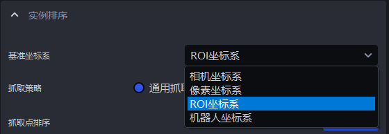
3.3.1 Base Coords
- Function description
Set a unified coordinate system for all instances to group and sort instances.
- Usage scenario
Common to depalletizing scenarios, random picking scenarios, and ordered loading/unloading scenarios
Strategies related to coordinates should first set the reference coordinate system
- Parameter description
| Parameter | Description | Illustration |
|---|---|---|
| Camera coordinate system | The coordinate system origin is above the object, and the positive Z-axis direction points downward; the XYZ values are the values of the center point of the object in this coordinate system | 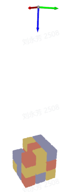 |
| ROI coordinate system | The coordinate system origin is approximately at the center of the pallet stack, and the positive Z-axis direction points upward; the XYZ values are the values of the center point of the object in this coordinate system | 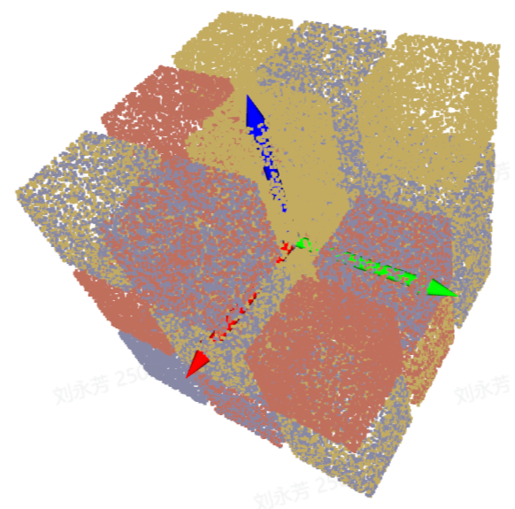 |
| Robot arm coordinate system | The coordinate system origin is on the robot arm itself, and the positive Z-axis direction generally points upward; the XYZ values are the values of the center point of the object in this coordinate system | 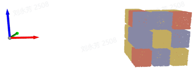 |
| Pixel coordinate system | The coordinate system origin is at the top-left vertex of the RGB image and is a 2D planar coordinate system; the X and Y values are the x value of the bbox detection box and the y value of the bbox detection box, and Z is 0 | 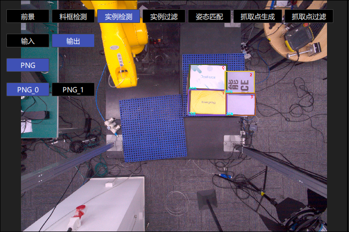 |
3.3.2 Picking strategy
- Parameter description
| Parameter | Description |
|---|---|
| Strategy | Select which value is used for grouping and sorting and how to sort it, including Pick Point center X/Y/Z coordinate values from large to small/from small to large (mm), from the middle to the sides / from the sides to the middle along the Pick Point XY coordinate axis (mm). Multiple items can be superimposed and executed in order. |
| Grouping step size | According to the selected strategy, divide Pick Points into several groups based on the step size. The grouping step size is the interval between two groups of Pick Points |
| Number of leading groups to keep | After grouping and sorting, how many groups of instances need to be retained |
| Strategy name* | Description | Grouping step size | Number of leading groups to keep | |
|---|---|---|---|---|
| Default | Range | Default | ||
| Pick Point center X/Y/Z coordinate values from large to small / from small to large (mm) | Use the X/Y/Z coordinate values of the Pick Point center for grouping and sorting | 200.000 | [0, 10000000] | 10000 |
| From the middle to the sides / from the sides to the middle along the Pick Point XY coordinate axis (mm) | Use the X/Y coordinate values of the Pick Point center and perform grouping and sorting in the direction of "middle to sides" or "sides to middle" | 200.000 | [0, 10000000] | 10000 |
3.3.3 Carton combination strategy
To solve the problems of low efficiency and limited applicable scenarios in traditional single-pick depalletizing, PickWiz adds a carton combination strategy in depalletizing scenarios to support picking multiple Target Objects in a single operation. It supports the core scenarios of "cartons with consistent dimensions" and "rectangular suction cups", covering more real project scenarios.
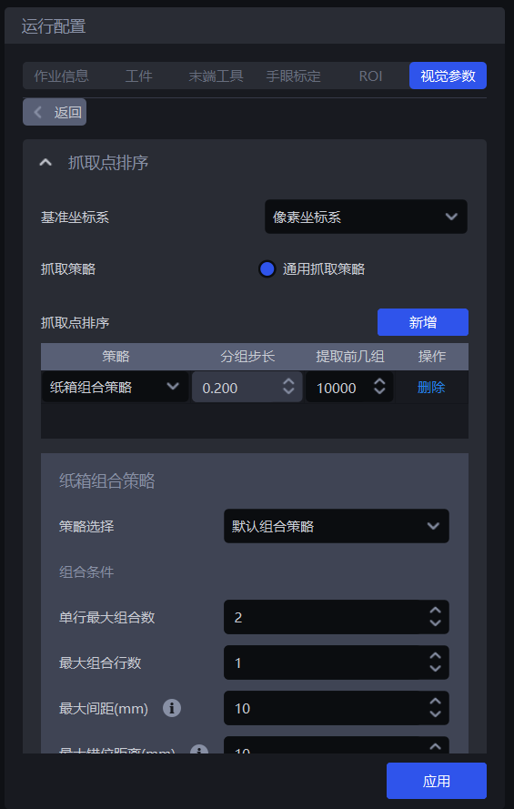
3.3.3.1 Multi-pick runtime configuration
(1)In sack single depalletizing or carton single depalletizing scenarios, enable Vision computation configuration - Vision computation acceleration.
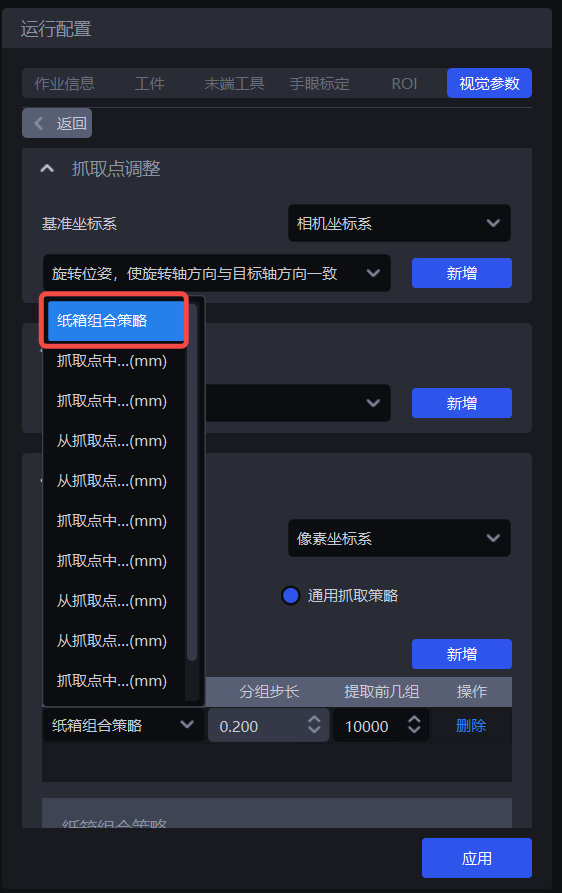
(2)Under the Pick Point sorting module, select the carton combination strategy;
(3)Strategy selection: available options are the default combination strategy or combination along a specified carton pose axis. These are two methods for finding the largest number of cartons that can be combined.
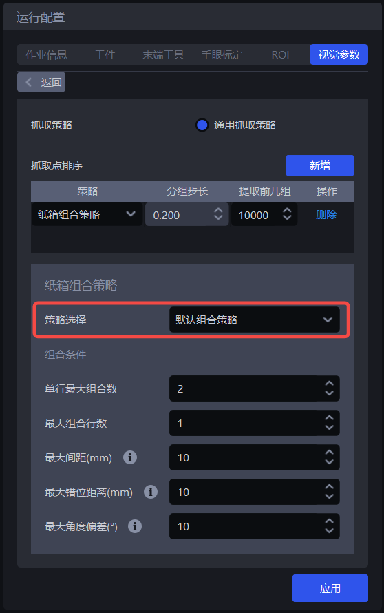
Default combination strategy: Find the largest number of cartons that can be combined along the X-axis and Y-axis directions of a carton Picking Pose.
Combine along a certain carton pose axis: Find the largest number of cartons that can be combined along the X-axis or Y-axis direction of a carton Picking Pose. This is suitable for scenarios where cartons are arranged in a straight line. When using this strategy, you need to choose the carton combination direction, namely the Picking Pose X-axis or the Picking Pose Y-axis.
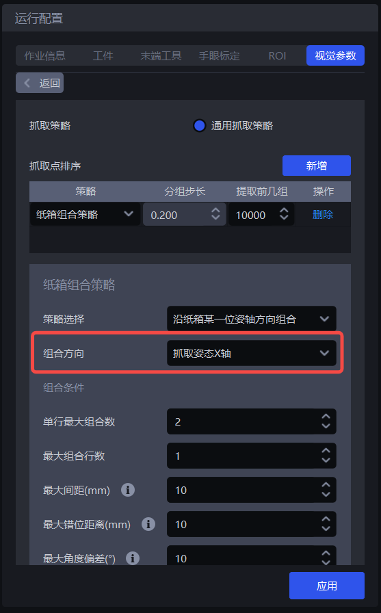
Note:
The combination direction is related to the positive and negative axis directions. Cartons can be combined only when they are on the same axis and in the same direction, and after combination, the orientation of the whole stack of cartons remains consistent with the orientation of a single carton before combination. Therefore, before combining cartons, make sure all cartons to be combined are placed in the same orientation, and unify the coordinates of the cartons to be combined to the same axis direction.
(4)Combination conditions: determine which cartons can be combined and how many can be combined at most.
Maximum cartons per row: the maximum number of cartons that can be combined in one row, default is 2.
Maximum number of combination rows: the maximum number of carton rows that can be combined, default is 1.
Maximum spacing (mm): cartons to be combined cannot be too far apart in the "combination direction", In the combination direction (axis direction), when the spacing between two adjacent cartons or cartons in different rows is less than this value, they can be combined into one group. The default is 10.
- Example: when searching for the maximum number of cartons along the Picking Pose X-axis, if the spacing between two adjacent cartons in the Picking Pose X-axis direction is 8 mm (≤10), they can be combined; if the spacing is 12 mm (>10), they cannot be combined.
Maximum misalignment distance (mm): cartons to be combined cannot be too far apart in the direction "perpendicular to the combination direction" . In the direction perpendicular to the combination direction (axis direction), when the misalignment distance between two adjacent cartons or cartons in different rows is less than this value, they can be combined into one group. The default is 10.
- Example: when searching for the maximum number of cartons along the Picking Pose X-axis, if two adjacent cartons are offset in the Picking Pose Y-axis direction by 8 mm (≤10), they can be combined; if they are offset by 15 mm (>10), they are no longer aligned and cannot be picked together.
Maximum angular deviation (°): cartons to be combined should face almost the same direction. In the combination direction (axis direction), when the rotational deviation angle of the cartons is less than this value, they can be combined into one group. The default is 10.
- Example: if a carton is rotated by 5° relative to the combination direction, as long as it does not exceed 10°, it can be combined; if it is rotated by 15° (>10), the orientation differs too much, the robot will be skewed when picking, and it cannot be combined.
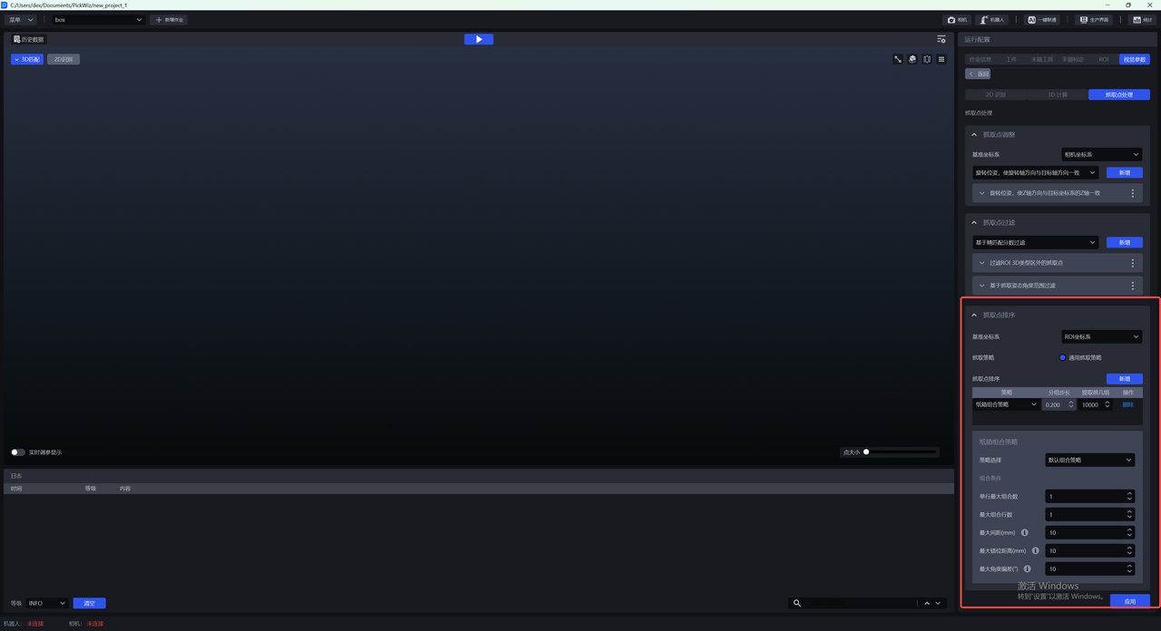
3.3.3.2 Robot configuration
(1)On the robot configuration page, add new placeholders in Vision computation communication message - Robot to PickWiz commands - Vision detection send command: maximum cartons per row and maximum number of combination rows, as shown below;
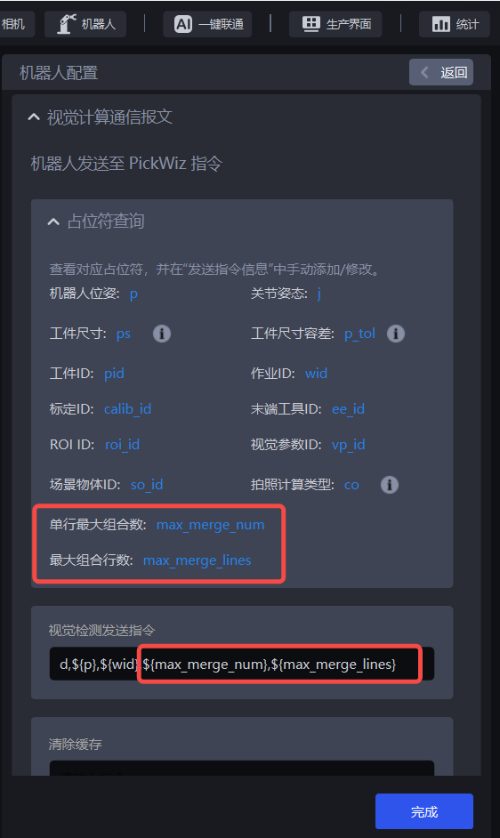
(2)In Vision computation communication message - PickWiz to robot commands - Pick-related information - Returned information when picking Target Objects, add Object Dimensions length, Object Dimensions width, and Target Object orientation.
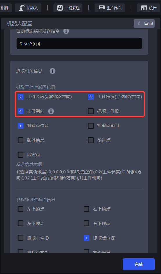
After the robot configuration is completed, click the Run button.
3.3.3.3 View multi-pick runtime results
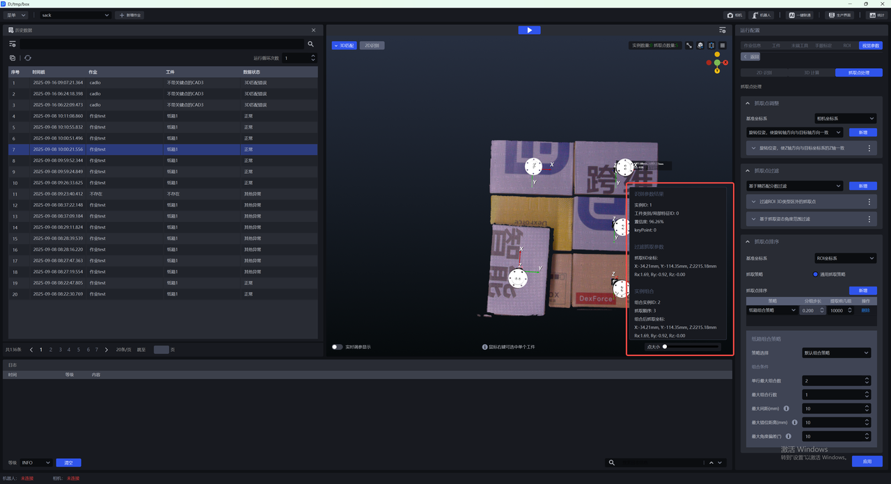
(1)In the 3D Matching window, hover the mouse over an instance to view the combined picking information of a single instance after carton combination, including 2D recognition results, Picking Pose, and instance combination information.
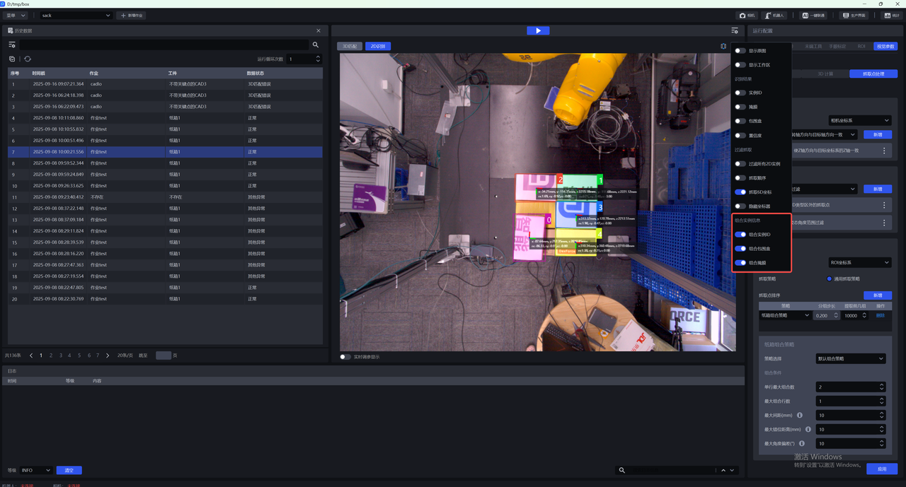
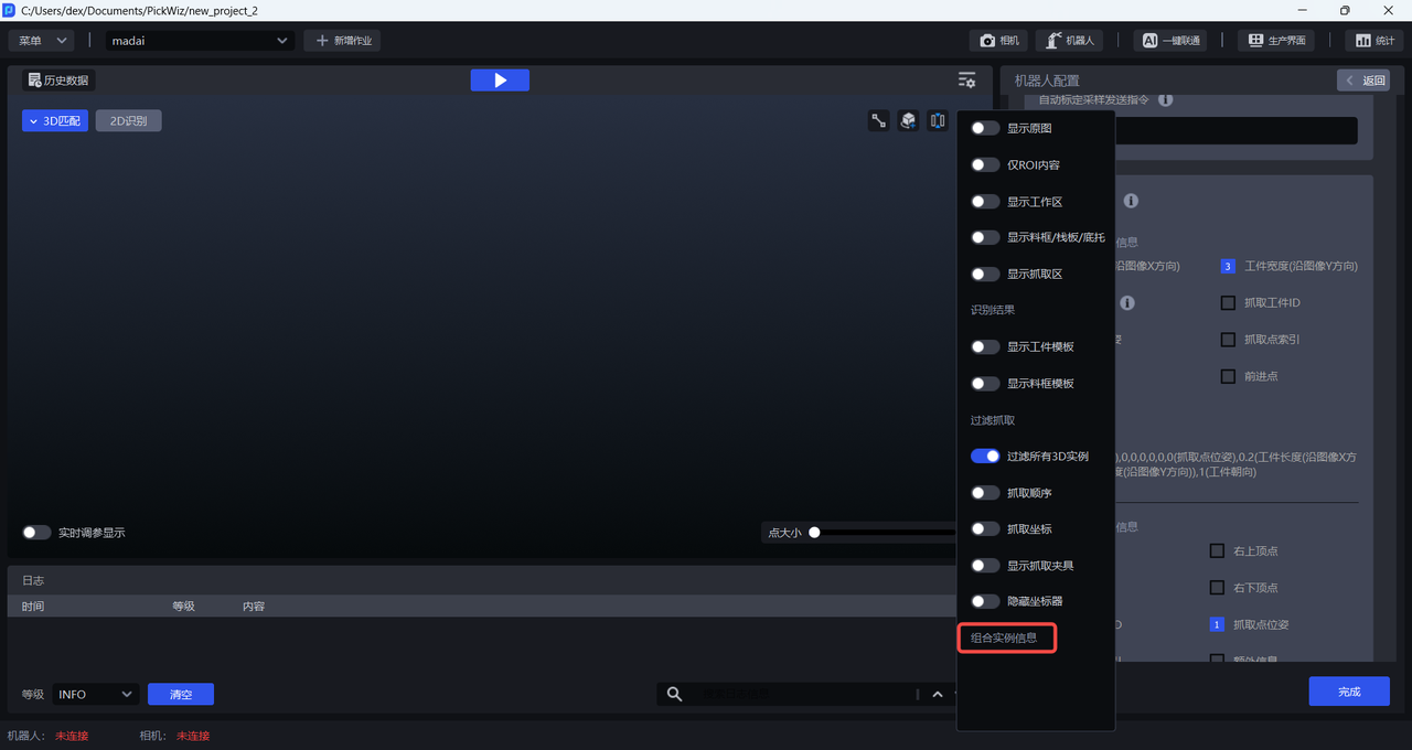
In the visualization window, click the Settings button in the upper right corner to set how the combined instance information is displayed.
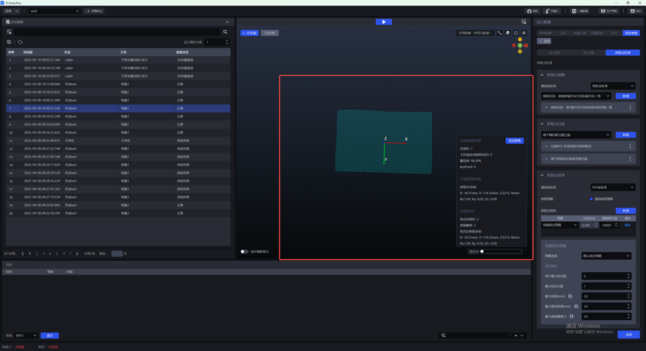
Right-click an instance to view the combined picking information and Target Object information of the single instance.
(2)In the 2D recognition window, you can use the relevant combination buttons in the menu bar to view the combined ID, combined Mask, and combined bounding box.