TCP server communication configuration
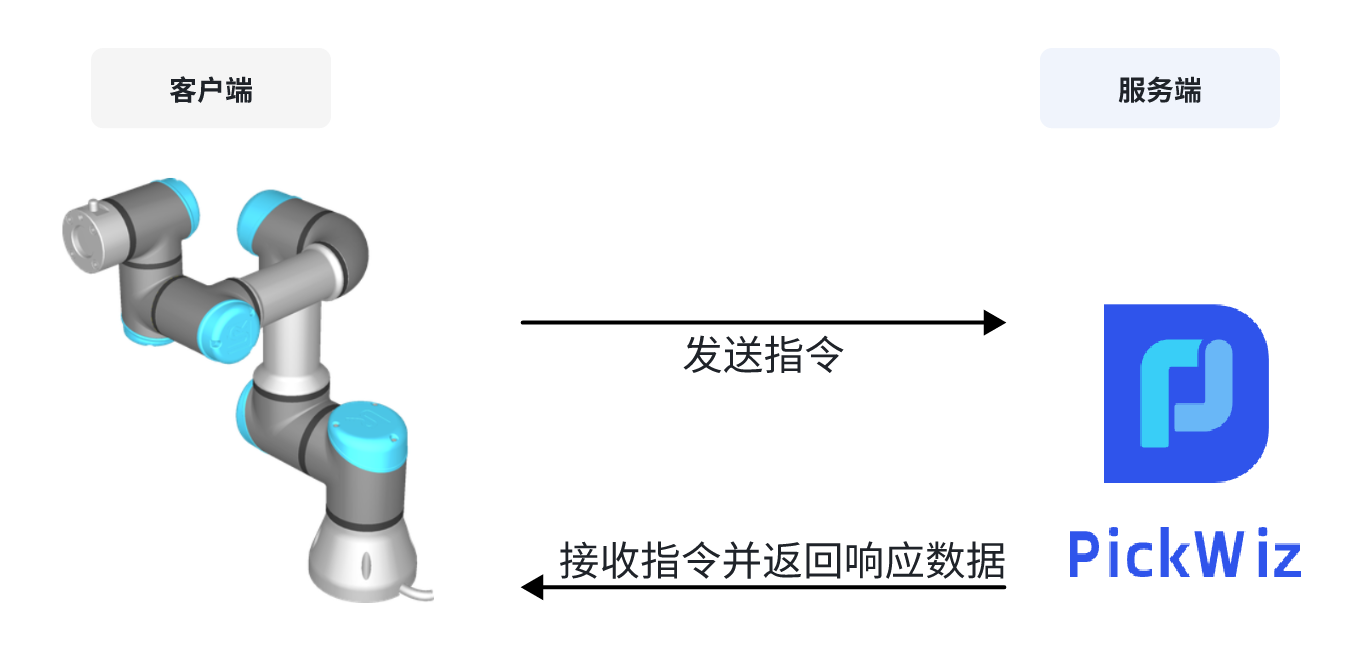
TCP is a communication method in which PickWiz acts as a TCP server and Robot acts as a TCP client. When PickWiz communicates with Robot, it does not actively control the Robot side. Instead, the Robot side sends TCP instructions to PickWiz, and PickWiz returns response data after receiving the instructions. Therefore, using TCP communication requires users to write programs on the Robot side to communicate with PickWiz.
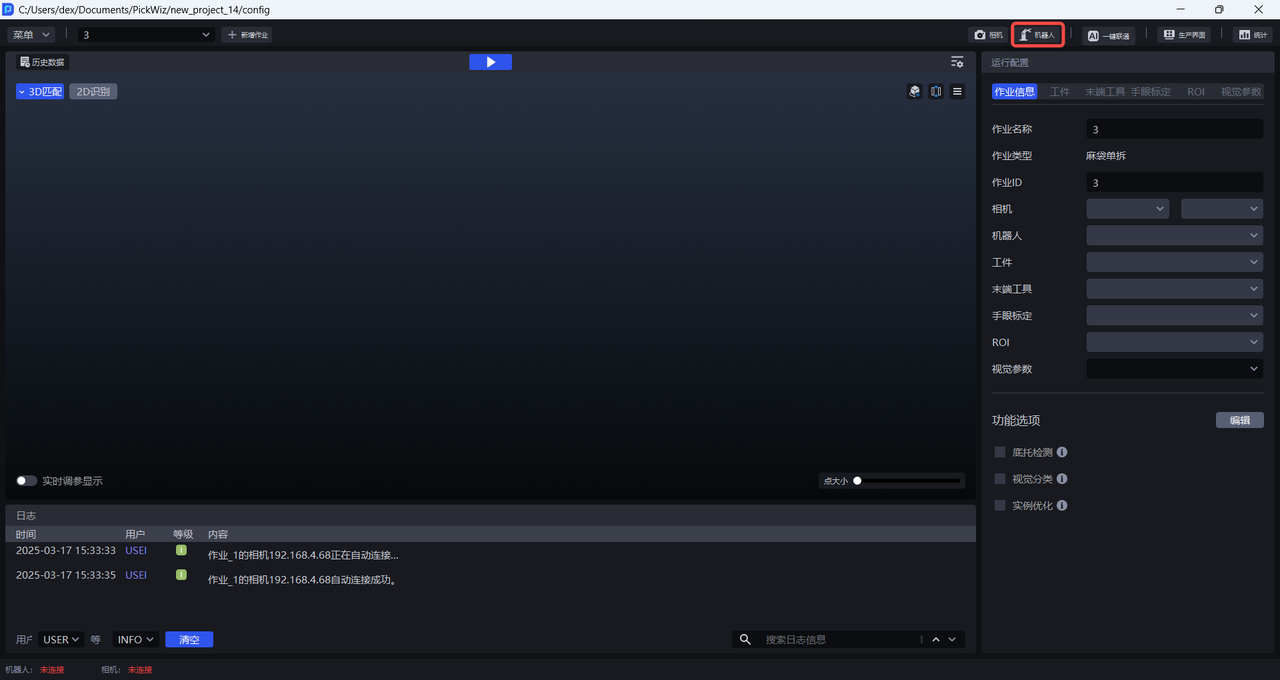
Before configuring Robot communication, please refer to the [Project Operation Guide] (项目操作指南.md) to create a new project, and then click Robot Configuration Panel on the main interface to enter the New Robot interface.
1. Add new Robot
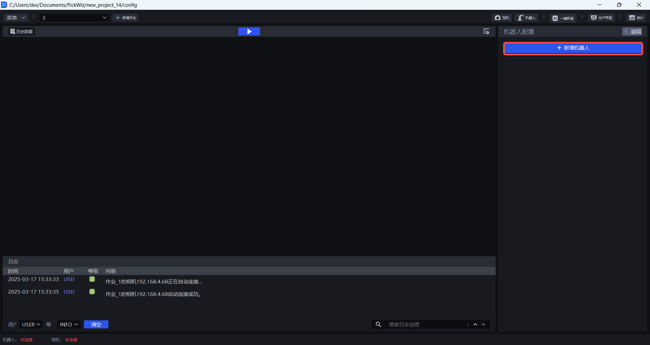
(1) Enter the Add Robot interface and click +Add Robot
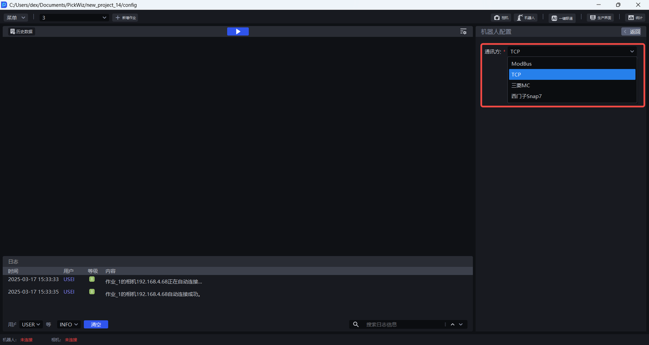
(2) Select TCP server as the communication method, click Next to enter the Robot Configuration interface
2. Configure Robot
In the Robot Configuration interface, you can configure Robot information, basic communication configuration, and customized communication message configuration.
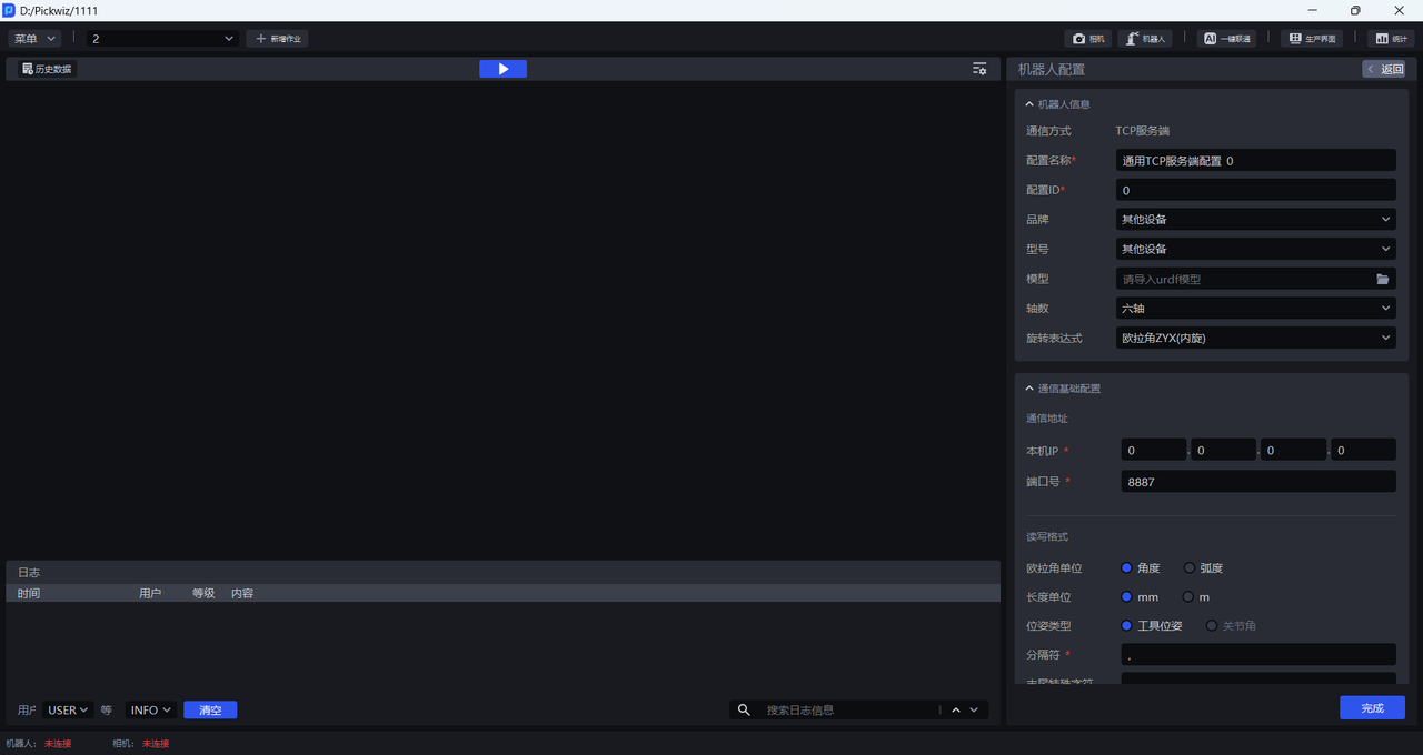
2.1 Robot information configuration
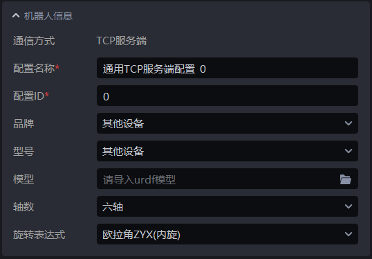
| Configuration Item | Description |
|---|---|
| Communication method | The communication protocol used to establish communication between PickWiz and Robot, which cannot be modified |
| Configuration name | The name of Robot configuration, supports Chinese and English, numbers, and characters |
| Configuration ID | The unique identification ID of the Robot configuration, which can be modified and only supports numbers |
| Brand | The brand of the Robot. If the Robot is connected to a PLC, select the brand. Other equipment |
| Model | The model of the Robot. If the Robot is connected to a PLC, select the model. Other equipment |
| Model | When selecting another device for brand and model, you need to upload the model of the device. The format of the model file is urdf |
| Number of axes | The number of axes of the robot arm owned by the Robot, optional three axes, four axes, or six axes |
| Rotation expression | Describes Robot's posture in three-dimensional space. Currently, there are two methods: Euler Angles and rotation vector. The order of Euler Angles can be modified. |
2.2 basic communication configuration
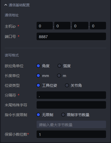
| configuration item | Description | |
|---|---|---|
| communication address | host ip | host ip address, the default is 0.0.0.0 | in TCP communication mode
| port number | Robot connects to the designated port of the host. The default port number is 8887. Generally, there is no need to modify | .|
| read and write format | Euler Angles unit | Euler Angle's unit, optional angle, radian, default angle. |
| length unit | Robot uses the length unit, including Robot Pose, Target size, etc. The default is mm | |
| pose type | Robot Pose representation method, default tool pose. The tool pose refers to the pose of the Robot End-effector; the joint angle refers to the pose of each joint of the Robot. The pose combination of each joint can determine the pose of the robot arm or End-effector. When selecting other equipment for the Robot brand and model, the pose type can only select the tool pose | by default.|
| delimiter | The delimiter can be filled with any character except the escape characters \n, \r, and \t. | |
| Some robots may receive or send a message that requires some special characters at the end, such as \n\r. You can fill in these special characters here. The software will append these special characters at the end when sending each message. When receiving each message from the robot, it will try to remove the special characters at the end (if any). | ||
| Instruction length limit | Some robot arms can only receive or send a specified number of bytes of data in one message, so you can set the number of bytes in a message here | |
| Retain the number of decimal places | The floating point data in theRobot instruction retains several decimal places and only supports numbers. The default is 1 | |
2.3 Custom communication message configuration
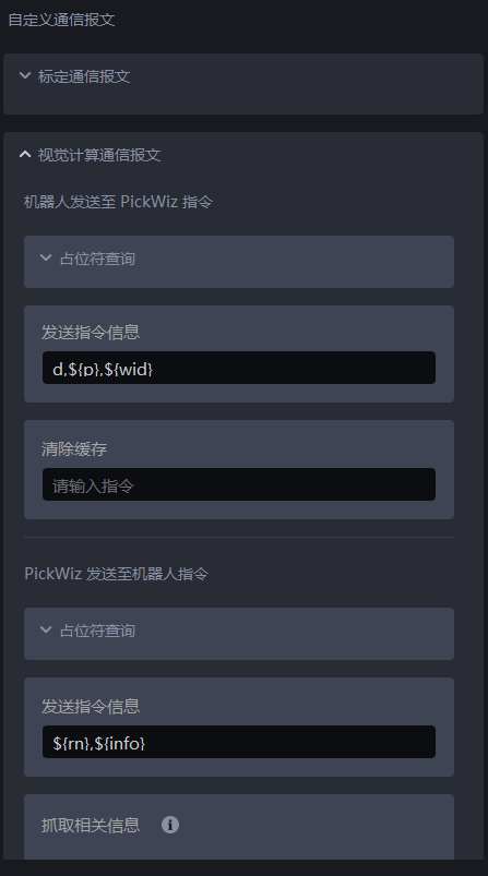
General Instruction Rules
3. TCP command description
3.1 calibration communication message
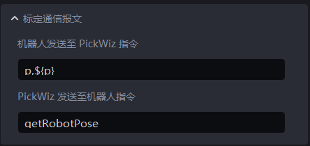
**Robot sent to PickWiz command **
p: Position information of RobotEnd-effector
$(p): Output the pose information of RobotEnd-effector, 6-bit data
PickWiz sends to Robot command
- getRobotPose: Get the coordinates of Robot
Example
PickWiz sends a request to Robot to getRobotPose, and Robot returns Robot coordinates p,${p} to PickWiz.
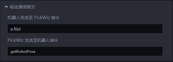

PickWiz sends a request (getRobotPose) to Robot, and Robot returns Robot coordinates p,${p} to PickWiz.
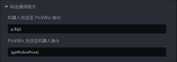
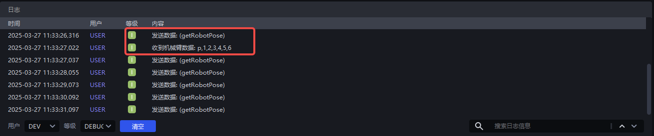
PickWiz sends a request to Robot for getRobotPose, and Robot returns Robot coordinates ‘p,${p}\n’ to PickWiz.
When Robot returns Robot coordinates to PickWiz that do not contain custom characters, PickWiz cannot match the instruction; when Robot returns Robot coordinates to PickWiz that contain custom characters, the software can match the instruction.
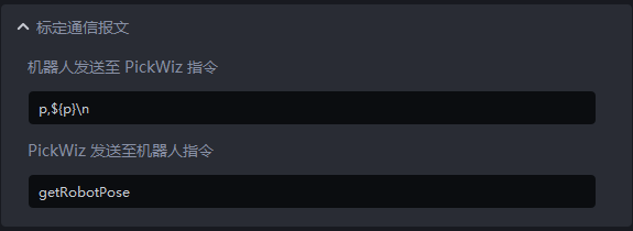
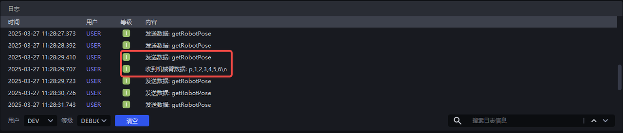
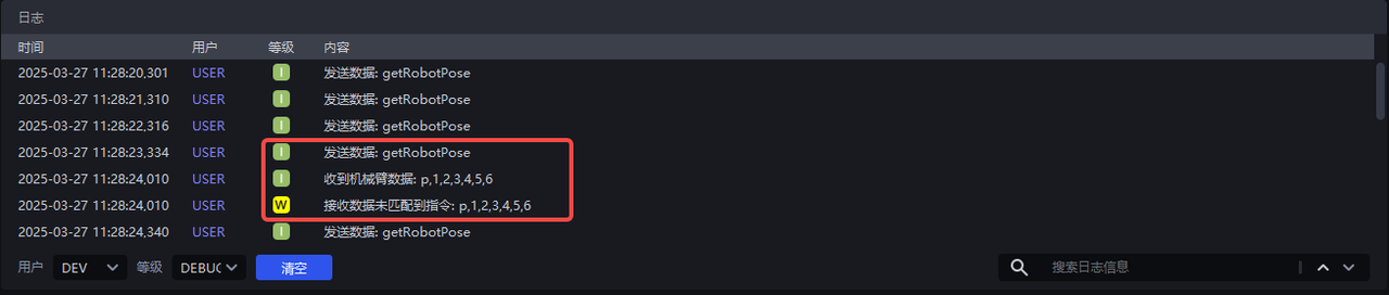
Or write "\n" in the special character at the end, and the software will automatically judge and analyze it.
3.2 visual computing communication message
3.2.1 Robot sent to PickWiz command
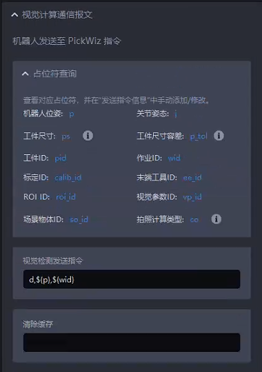
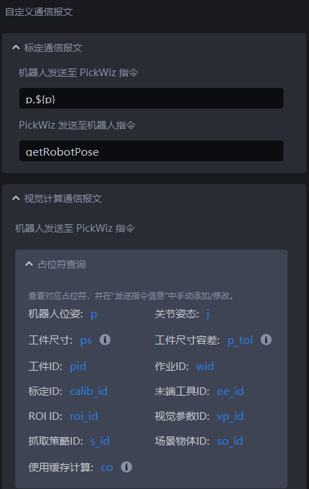
Placeholder Query
Placeholders refer to symbols or marks used in programming. The placeholders will be replaced by specific content/data during actual communication.
| Placeholder | Description |
|---|---|
| p | Robot tool pose, 6-digit data when the pose type is tool pose, Robot returns the current RobotEnd-effector pose to PickWiz |
| j | Robot reference joint pose, 6-bit data when the pose type is joint angle, Robot needs to send the reference joint pose, which is used to calculate the Pick Point joint pose closest to the reference joint pose |
| ps | Target size incoming materials are Targets of multiple sizes, and Robot needs to automatically adjust the crawling strategy according to different sizes. In different Scenes, the Target size digits passed in from the Robot side are different from the Target information corresponding to the digits. The circular Scene inputs 1 digit, representing the radius; the cylindrical Scene inputs 2 digits, representing radius\height; the carton Scene inputs 3 digits, representing length\width\height; the quadrilateral Scene inputs 2 digits, representing width\length. |
| p_tol | Target size tolerance The incoming materials are Targets of multiple sizes, and the Robot needs to automatically adjust the crawling strategy according to different sizes. In different Scenes, the number of digits of the Target size tolerance passed in by the Robot side is different from the Target information corresponding to the number of digits. The number of digits passed in to the circular Scene is 1, representing the tolerance of the radius; the digits passed in to the cylindrical Scene are 2 digits, representing the tolerance of radius\height; the number of digits passed in to the quadrilateral Scene is 2 bits, representing the tolerance of width\length. |
| pid | TargetID, used for Robot to automatically switch the crawled Target |
| wid | TaskID, used by Robot to automatically switch Task |
| calib_id | Calibration ID, used for Robot to automatically switch Eye-hand calibration configuration files |
| ee_id | End-effectorID, used to automatically switch End-effector when Robot performs tasks |
| roi_id | ID of ROI, used by Robot to automatically switch ROI |
| vp_id | Visual ParameterID, used by Robot to automatically switch visual Parameter |
| so_id | Scene ObjectID, used by Robot to automatically switch Scene Object |
| co | Photo calculation type, used to switch between different photo modes, set according to on-site use. 0: Retake pictures and visual calculations 1: Use cached images (last collected images) for visual calculations 2: Only take pictures and take pictures 3: Take pictures with "random attitude automatic sampling" 4: Real-time correction of visual drift 5: Use historical data for visual calculations 6: Shut down the industrial computer |
Visual inspection sends instructions
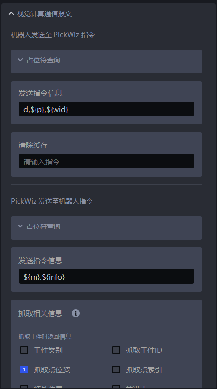
Configure command character text box, used to configure the content of commands sent by Robot to PickWiz; the default is: d,{wid}.
d: Instruction identifier to avoid repeated confusion of multiple instructions. For example, in calibration communication, the sending instruction identifier is p.
$(p): RobotEnd-effector’s pose information, 6-bit data
$(wid): TaskID, 1 digit, used for Robot to switch Tasks
Example
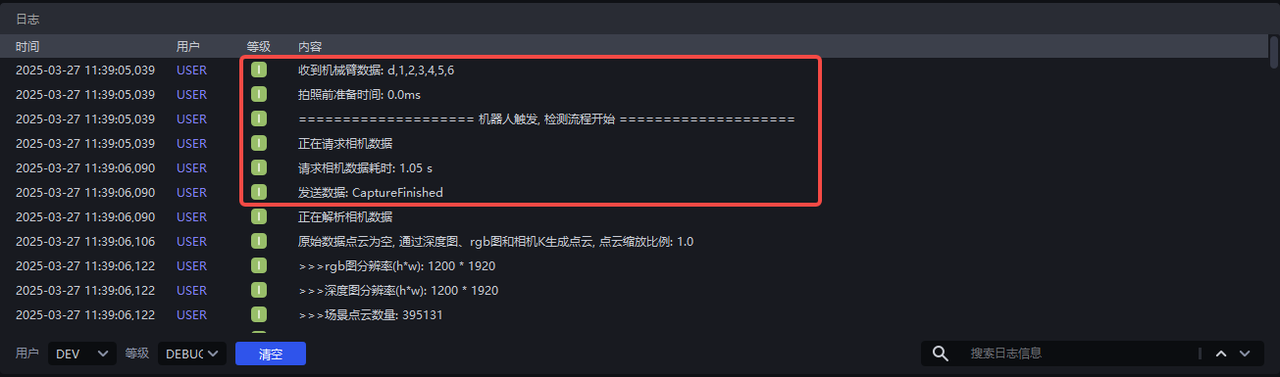
The sending command information is set to d,${p}, Robot only sends pose information to PickWiz, triggering the process
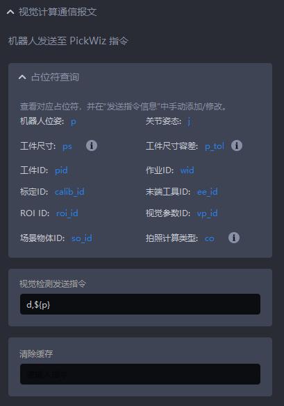
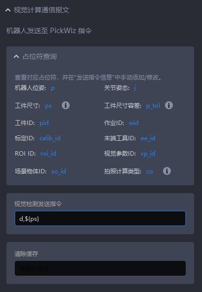
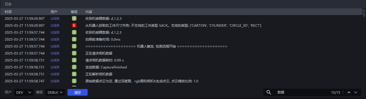
The sending command information is set to d,${ps}. In the sack single removal Scene, Robot sends the Target size to PickWiz, and an error will be reported and it is only applicable to cartons, circles, cylinders, and quadrilaterals; in the carton single removal Scene, Robot sends the length, width, and height of the carton to PickWiz, triggering the detection process.
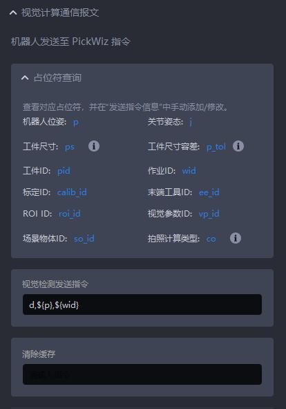
The sending command information is set to d,{wid}, Robot sends pose information and TaskID to PickWiz, and automatically switches the detection process of Task1, 2, 4, and 5.
Clear cache
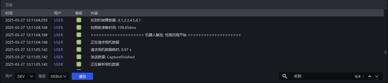
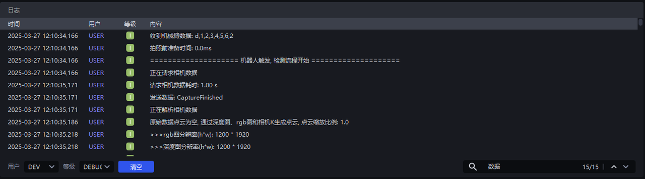
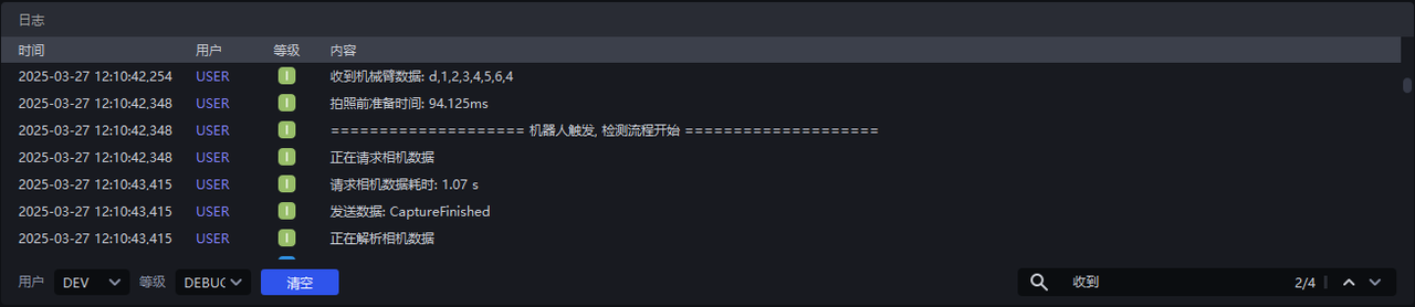
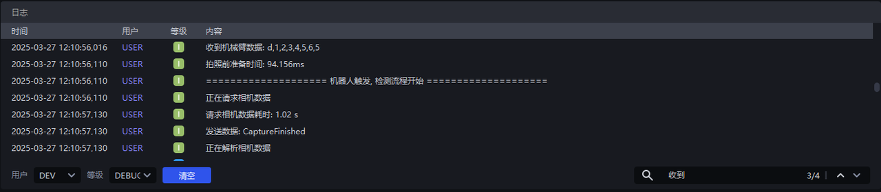
Only for the case of shoot one and capture many, clear the current remaining instance cache and take pictures again when the detection process is triggered next time.
Pre-information:
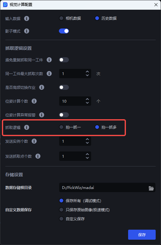
You need to understand the usage logic of "Visual Computing Configuration - Crawl Logic":
- Shoot one, grab one: means to visually take a picture once, calculate it once, send the result to Robot after calculation, discard the redundant results, Robot performs the relevant grabbing action, and then repeats.
- Shoot one, grab many: It means to visually take a photo once, calculate it once, send the calculation result to Robot, save the redundant visual results, and Robot performs the relevant grabbing action. The next time Robot sends a photo calculation instruction, it will first check whether the saved visual result meets the requirements. If so, the logic of photo + calculation will not be executed, and the result will be directly returned to Robot, and then repeat.
Example
When Capture one, grab multiple is unchecked, every time Robot triggers the detection process, PickWiz will perform photo calculations.
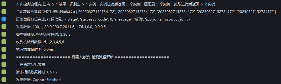
In the visual computing configuration, check Shoot one, grab multiple, and PickWiz can realize photo calculation and capture multiple times at one time. As shown in the figure below, 5 instances were identified. The first capture was triggered by PickWiz, and the next 4 captures were triggered by Robot. During the last 4 captures, Robot sent pose information to PickWiz to trigger the detection process. PickWiz did not perform photo calculations, but directly returned to the capture pose.
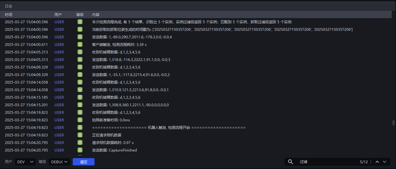
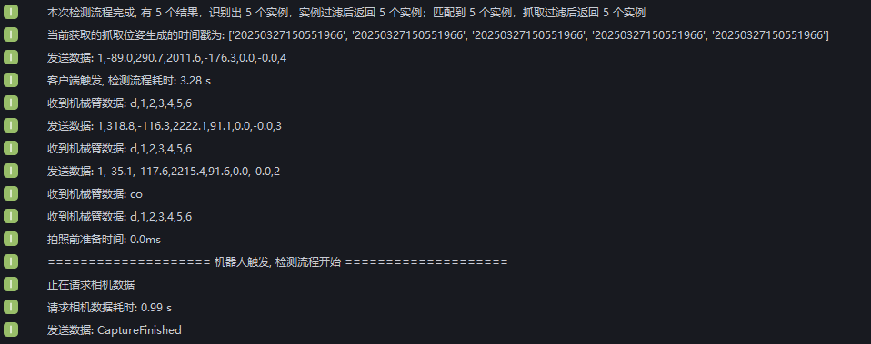
The first capture is triggered by the client, and the second and third captures are triggered by Robot. Robot sends pose information to PickWiz to trigger the detection process. PickWiz does not perform photo calculations, but directly returns the capture pose. Then enter the co command to clear the cache, and grab PickWiz for the fourth time and start taking pictures again.
3.3 PickWiz sent to Robot command
Placeholder Query
Placeholders refer to symbols or marks used in programming. The placeholders will be replaced by specific content during actual communication.
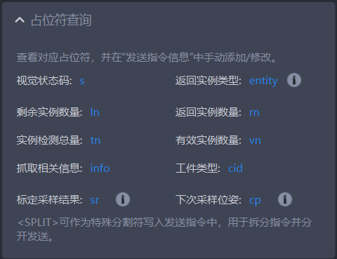
| Placeholder | Meaning |
|---|---|
| s | Visual status code, 1 bit, the default value is 100 for success, 0 for other exceptions, customizable configuration |
| entity | Returns the instance type, 1 bit, 1 is pallet, 0 is Target |
| ln | The number of remaining instances, 1 digit, under the fetching logic of shoot one, grab many, returns the current number of remaining cached instances |
| rn | Returns the number of instances, 1 digit, returns the number of instances identified by Instance Segmentation2D. The value is less than or equal to the number of sent instances. If there are multiple instances, the length of the fetched related information will increase with the number of returned instances |
| tn | The total number of instance detections, 1 digit, the number of detection instances that are not instance filtered |
| vn | Valid instance number, 1 digit, the number of detected instances after instance filtering |
| info | Grab relevant information |
| cid | Target type |
| sr | Calibration sampling result is an automatic sampling calibration instruction. Different calibration sampling results correspond to different signal values. 0: The minimum number of samples has been reached 1: The new sample was successfully added 11: The new sample failed 12: Automatic sampling ended and the sample list was executed 13: Failed to generate the sampling attitude 14: The calibration sampling page was not entered 15: System error |
| cp | The next sampling pose is the automatic sampling calibration instruction. The next time Robot collects the moving position of the calibration sample |
| <SPLIT> | Special delimiter, no need to add ${} when using, add this mark directly in the command, at this position, the data will be forcibly split. Note: This function is mutually exclusive with the function of splitting data by number of characters, and this function has a higher priority. |
Visual inspection sends instructions
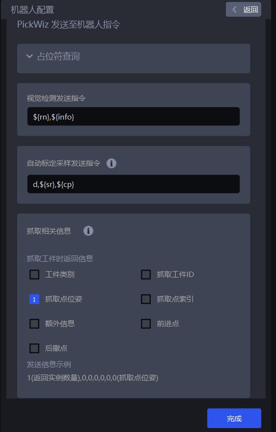
Configure the content of instructions sent by PickWiz to Robot. The default is
Automatic calibration sampling and sending instructions
When the Eye-hand calibration method is "random posture automatic sampling", you need to set this command, otherwise Robot cannot communicate with PickWiz
Grab relevant information
The length of the crawling related information expressed below is the number of digits of the length of a single Pick Point. If it is multiple Pick Points, the length is the number of digits x the number of Pick Points.
Common information for all Scenes
Field Description Grab TargetID 1 digit; indicates the current Target serial number Pick Point pose 6 bits; represents the Pick Point pose data Pick Point index 1 bit; indicates the current Pick Point serial number Additional information 1 bit; indicates the custom additional information of the current Target Forward point Only applicable when the pose type is Joint Angle, the length is 1 + the number of path points; the format is (number of path points, joint path point posture from pre-grab point to Pick Point) Fallback point Only applicable when the pose type is Joint Angle, the length is 1 + the number of path points; the format is (number of path points, joint path point posture from Pick Point to Fallback Pick Point) Specific Scene information
Carton/sack depalletizing
Product length: 1 digit, current product length (along the x direction of the image)
Product Width: 1 bit, current product width (along the y direction of the image)
Product direction: 1 bit, product orientation (0: horizontal along x, 1: vertical along y)
Position of the upper left vertex of the tray: 3 bits (x, y, z), indicating the position information of the upper left vertex of the tray in the current Scene
Position of the upper right vertex of the tray: 3 bits (x, y, z), indicating the position information of the upper right vertex of the tray in the current Scene
Position of the lower left vertex of the tray: 3 bits (x, y, z), indicating the position information of the lower left vertex of the tray in the current Scene
Position of the lower right vertex of the pallet Position: 3 digits (x, y, z), indicating the position information of the lower right vertex of the pallet in the current Scene
Carton depalletizing information:
- Product Height: 1 digit, current product height
Ordered/unordered grabbing of wafers:
- Circular Radius: 1 digit, the current product’s circular surface radius
Cylinder ordered/unordered grabbing:
Circular Radius: 1 digit, the current product’s circular surface radius
Cylinder height: 1 digit, current product height
Unordered fetching:
- Target Category: 1 bit, current Target category, used in Scenes that identify multiple types of Targets.
Quadrilateral ordered/unordered grabbing:
Quadrilateral length: 1 digit, current product length
Quad width: 1 bit, current product width
Visual Status Code
Visual status codes are used for troubleshooting. The recommended status codes are as follows:
${s} needs to be configured in Visual Inspection Send Command
- If the visual status code is not customized, the default value is
100returned on success, and0is returned by default for other exceptions.
| Content information | Default value | Related nodes |
|---|---|---|
| Success | 100 | |
| Detect base plate | 301 | Foreground Builder |
| Container frame not detected | 4000 | Container frame detection (Container Builder) |
| Instance not detected | 5000 | Instance Segmentation(Instance Builder) |
| No pose detected | 6000 | Pose Estimation (Pose Builder) |
| Pick Point not detected | 7000 | Pick Point Generation (Grasp Builder) |
| No path detected | 8000 | Robot Trajectory Builder (Trajectory Builder) |
| Instance size not detected | 9000 | Target Size Builder (Size Builder) |
| Empty ROI | 1101 | ValidPoints Criteria |
| No valid instance | 12000 | Instance Criteria |
| No valid Target pose | 13000 | Pose Criteria |
| No valid Pick Point | 14000 | Pick Point filter (Grasp Criteria) |
| All detection results are collision-uncatchable | 15000 | Collision detection filter (Collision Criteria) |
| No instance with valid size | 17000 | Target size filter (Size Criteria) |
| Exception | 20000 | General exception error, please check the log to confirm |
| Insufficient video memory | 20001 | General exception error, please check the log to confirm |
| Invalid input (please check the algorithm Parameter) | 20002 | General exception error, please check the log for confirmation |
| Full inspection | 20003 | Point Cloud processing operator related (full_detect_judgment) |
| Foreign object detection anomaly | 20004 | Instance filter operator related (foreign_matter_judgement) |
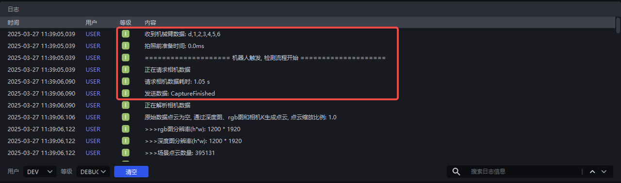
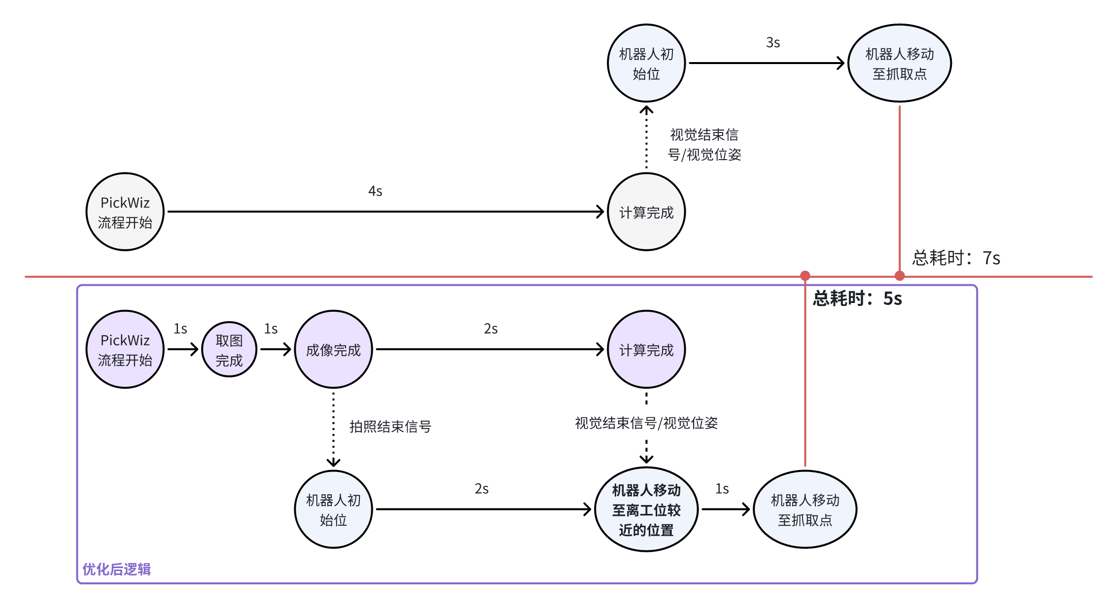
Imaging completed
"Imaging completed" means that the Camera has completed capturing the image and processing the image data.
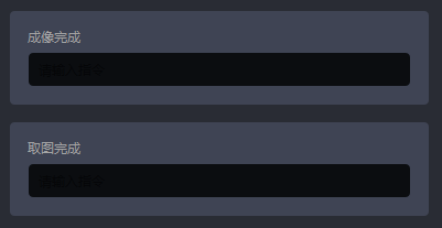
Picture taken
"Image acquisition completed" means that the camera obtained the image data after taking the picture, but did not generate a Point Cloud or perform image processing. It is often used by a Robot to send out a command signal before the imaging is completed, triggering the system/script to perform the next operation without waiting for the imaging to be completed (because the completion of imaging takes more time than the completion of image acquisition), which can reduce the time of the overall process to a certain extent.
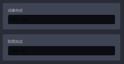
Example
During the capture/imaging completion, configure the command CaptureFinished. After the Camera capture/imaging is completed, PickWiz will send the CaptureFinished command to the Robot, which can trigger the next step.

4. Edit, copy, and delete Robot
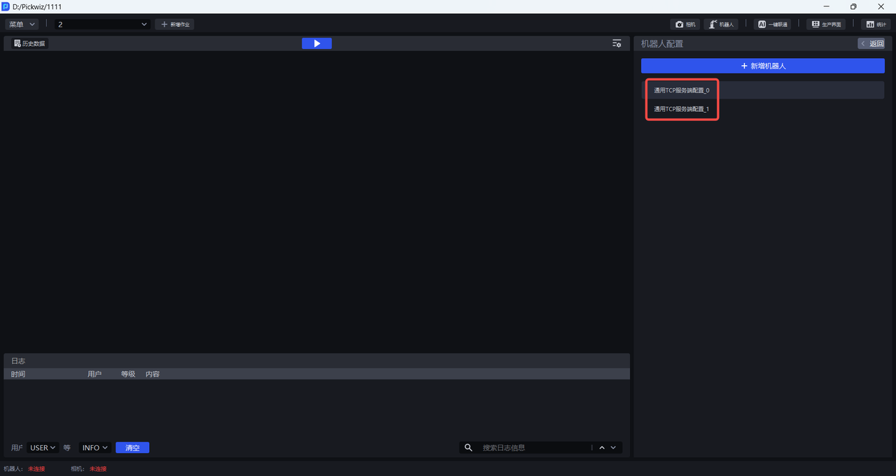
(1) Edit Robot configuration
In the Add Robot interface, left-click the Robot configuration to edit the selected Robot configuration.
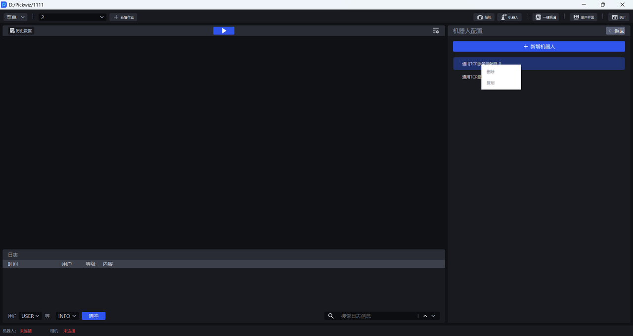
(2) Copy Robot configuration
Right-click the Robot configuration on the Add Robot interface to copy the selected Robot configuration.
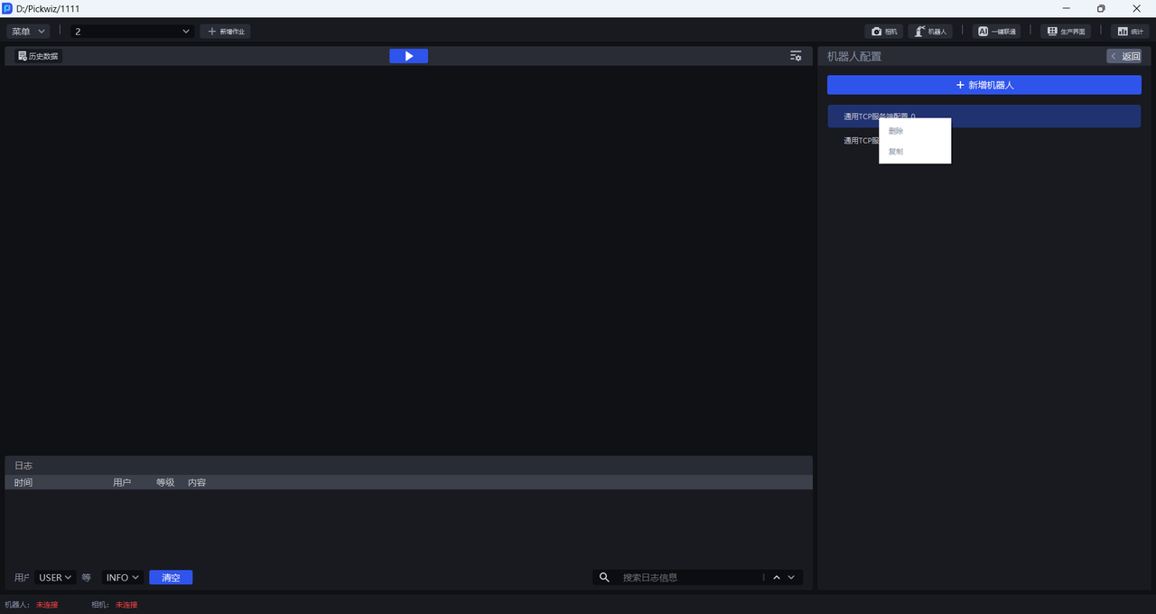
(3) Delete Robot configuration
Right-click the Robot configuration on the Add Robot interface to delete the selected Robot configuration.
5. Select Robot configuration
After completing the TCP communication configuration, you can select the Robot configuration for the current TaskScene in the Taskmain interface and select the corresponding Robot configuration in the Robot configuration selection column. PickWiz will try to establish communication with the Robot through the TCP communication protocol.
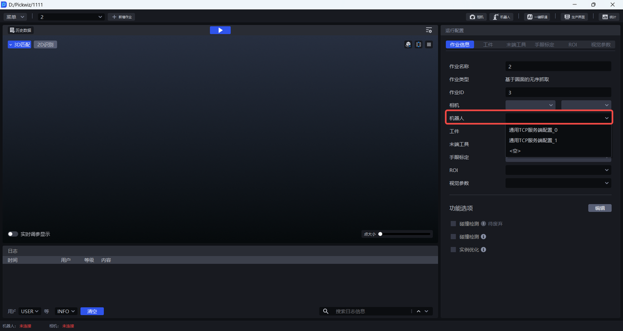
If the communication connection is successful, the Robot communication connection status in the lower left corner of the main interface will display "Connected".

If the communication connection fails, the Robot communication connection status displays "Not Connected". Please check whether the network cable between the Robot and the industrial computer is firmly connected, whether the program loaded and run by the Robot system is correct, and then reconfigure the Robot.

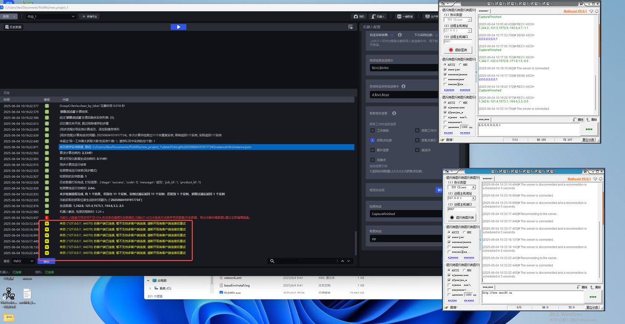
When PickWiz is used as the server, when multiple Robot clients are connected, in addition to the connected client, when other clients try to connect, the log will give a prompt to reject the request, as shown in the figure below.