Eye to hand four-axis Robot calibration
This article introduces how to perform Eye-hand calibration on a four-axis Robot in the Eye to hand (Eye to hand) Scene.
1. Random attitude sampling calibration
1.1 Preparation before calibration
Before Eye-hand calibration, the following preparations need to be made:
(1) Complete the hardware construction of the 3D visual guidance kit
Please refer to [3D Vision Guidance Kit Hardware Construction] (../常用操作/3D视觉引导套件硬件搭建.md) to complete the installation and connection of Robot, Camera and industrial computer
(2) Complete the new project and new Task
Please refer to Project Operation Guide and Task Operation Guide to create a new project and Task
(3) Complete the Camera connection and parameter adjustment and configure the Task information
Please refer to [Camera Connection and Parameter Adjustment Guide] (../常用操作/相机连接与调参指南.md) to connect the Camera, adjust the Camera imaging quality, verify the Camera accuracy, and configure the Task information
(4) Complete Robot communication configuration
Please refer to Robot Configuration and Communication Operation Guide to establish communication between Robot and Pickwiz
(5) Prepare materials required for calibration
Please ensure that the Calibration Board is flat and clear, with no obvious scratches or dirt, and no bending or deformation.
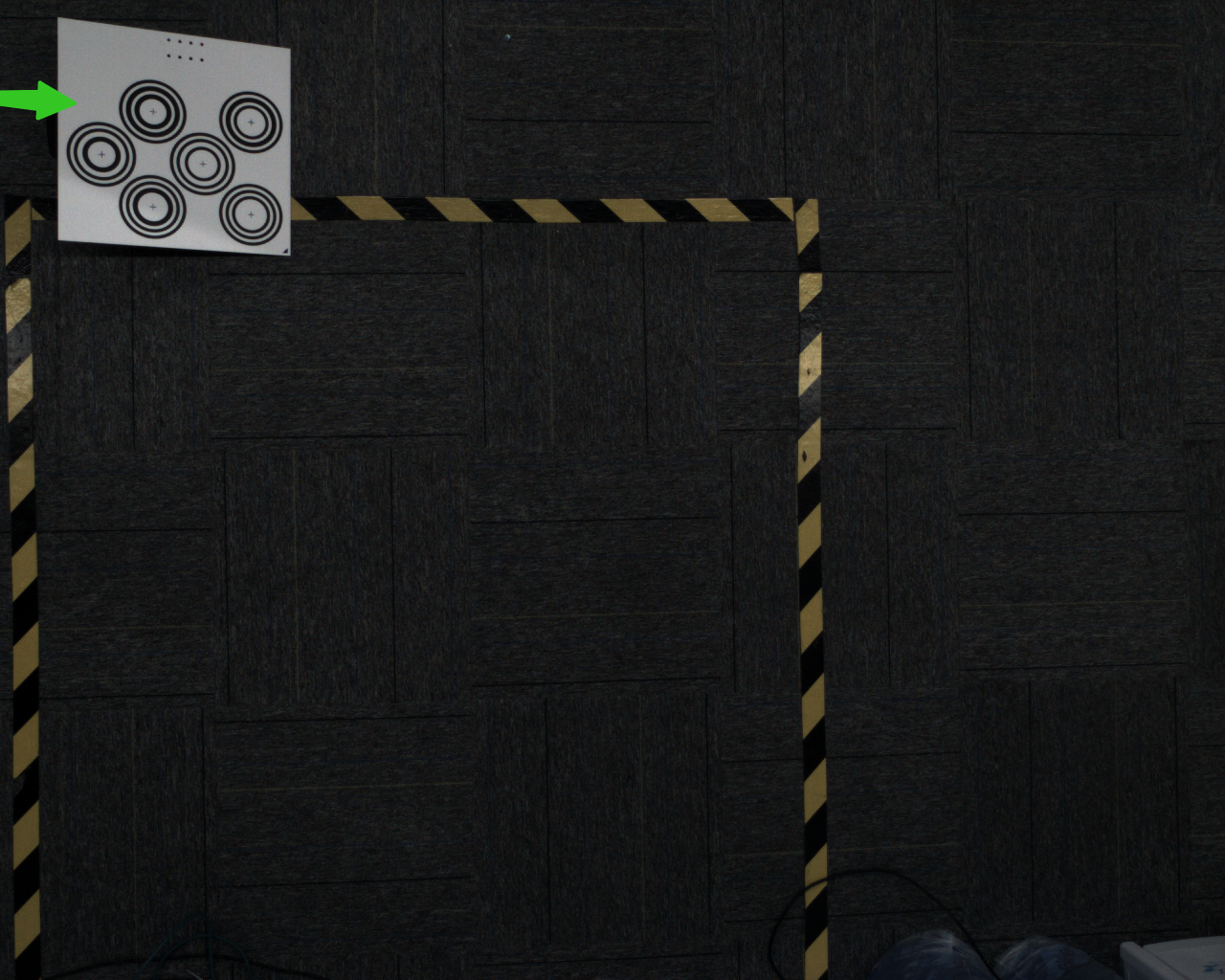
If the calibration method is random attitude sampling calibration, please ensure that the Calibration Board is placed on the work platform and within the camera's field of view.
1.2 calibration information configuration
Enter the Eye-hand calibration interface and click Add Eye-hand calibration to enter the calibration information configuration interface.
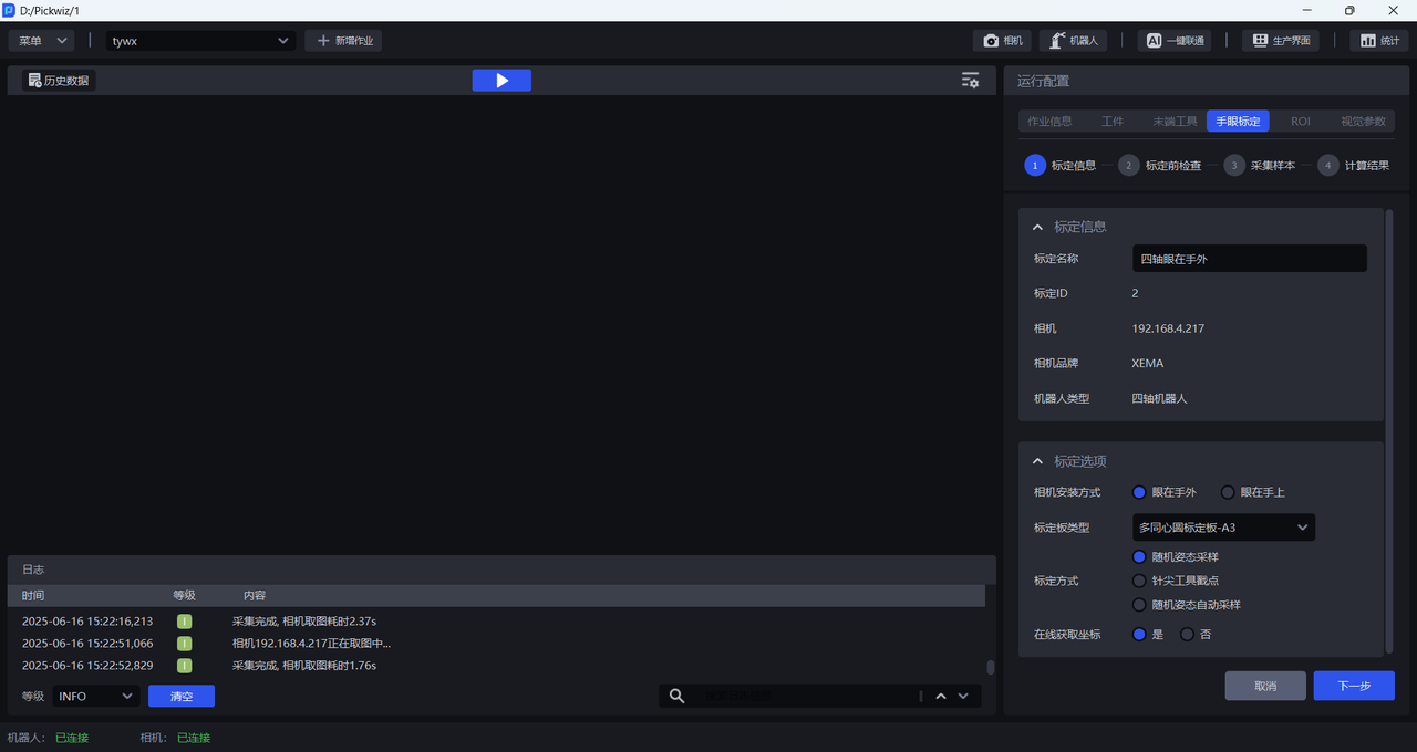
Calibration nameallows you to name the current calibration configuration yourself.Calibration IDis used by Robot to switch calibration configurationsCamerais the IP address of the currently connected CameraCamera Brandis the brand of the currently connected CameraRobot typeis consistent with the Robot type in Robot configurationCamera installation methodselectEye to handCalibration Board Typeselects the current Calibration Board type
The appropriate Calibration Board is mainly determined by the Robot type and Camera height. Please refer to the following table to select the appropriate Calibration Board according to the actual scene requirements.
| Robot type | Camera installation height | Select Calibration Board |
|---|---|---|
| six-axis Robot | Below 0.5 meters | A6 Multi-Concentric Circle Calibration Board |
| Below 1.5 meters | A5 Multi-Concentric Circle Calibration Board | |
| 1.5 meters -- 2.5 meters | A4 Multi-Concentric Circle Calibration Board | |
| 2.5 meters and above | A3 Multi-Concentric Circle Calibration Board | |
| three-axis/four-axis Robot | Below 0.5 meters | A6 Multi-Concentric Circle Calibration Board |
| Below 1.5 meters | A5 Multi-Concentric Circle Calibration Board | |
| 1.5 meters -- 2.5 meters | A4 Multi-Concentric Circle Calibration Board | |
| 2.5 meters and above | A3 Multi-Concentric Circle Calibration Board |
Calibration methodSelectRandom attitude sampling calibrationIf the Robot has written a corresponding calibration program, and when sampling the Calibration Board, the Robot needs to run the calibration program and send the pose to PickWiz, then
Get coordinates online** selectYes; if the Robot has not written a corresponding calibration program, and when sampling the Calibration Board, you need to manually enter the pose of the RobotEnd-effector, thenGet the coordinates online**SelectNo.
1.3 Inspection before calibration
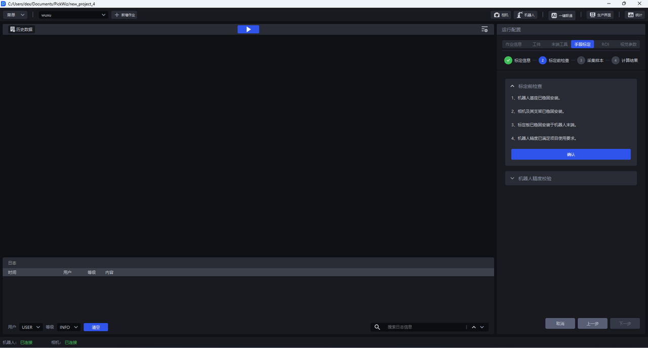
- Make sure the Robot base is firmly installed
Before performing eye-hand calibration, you should carefully check the installation of the Robot base. If the Robot base is not firmly installed, the Robot will shake significantly when it moves, affecting the Robot's accuracy and thus the calibration results.
Follow the steps below to check whether the installation of the Robot base meets the requirements:
First, the surface on which the Robot base is installed must be flat and clean;
Second, control the Robot to translate or rotate at a large speed at 100% speed, and observe whether there are signs of shaking in the Robot. If there is any shaking, please readjust the fixed Robot base to ensure that problems such as displacement and tilt do not occur when the Robot moves;
Third, check whether the Robot body and the base are tightly connected, and tighten the screws to prevent them from loosening.
- Make sure the Camera and its bracket are securely installed
Before performing eye-hand calibration, you should carefully check the installation of the Camera and its bracket. If the Camera and its bracket are not firmly installed, it will affect the camera imaging quality and thus the calibration results.
Follow the steps below to check whether the installation of the Camera and its bracket meets the requirements:
First, check whether the Camera bracket is a machine-mounted Target. The material of the bracket should avoid aluminum profiles;
Second, shake the bracket and observe whether there is obvious shaking in the bracket. If there is any shaking, please readjust the fixed bracket;
Third, shake the Camera and observe whether there is obvious shaking in the Camera to ensure that the Camera is installed securely.
- Make sure the Calibration Board is placed smoothly in the Camera's field of view
The Camera installation method is Eye to hand, and the Calibration Board needs to be installed on the End-effector to ensure that the Calibration Board is within the Camera's field of view.
- Ensure that Robot accuracy meets project usage requirements
If the Robot accuracy does not meet the project usage requirements, please refer to [Calibration Verification] (标定校验.md) to correct the Robot accuracy.
1.4 Collect Sample
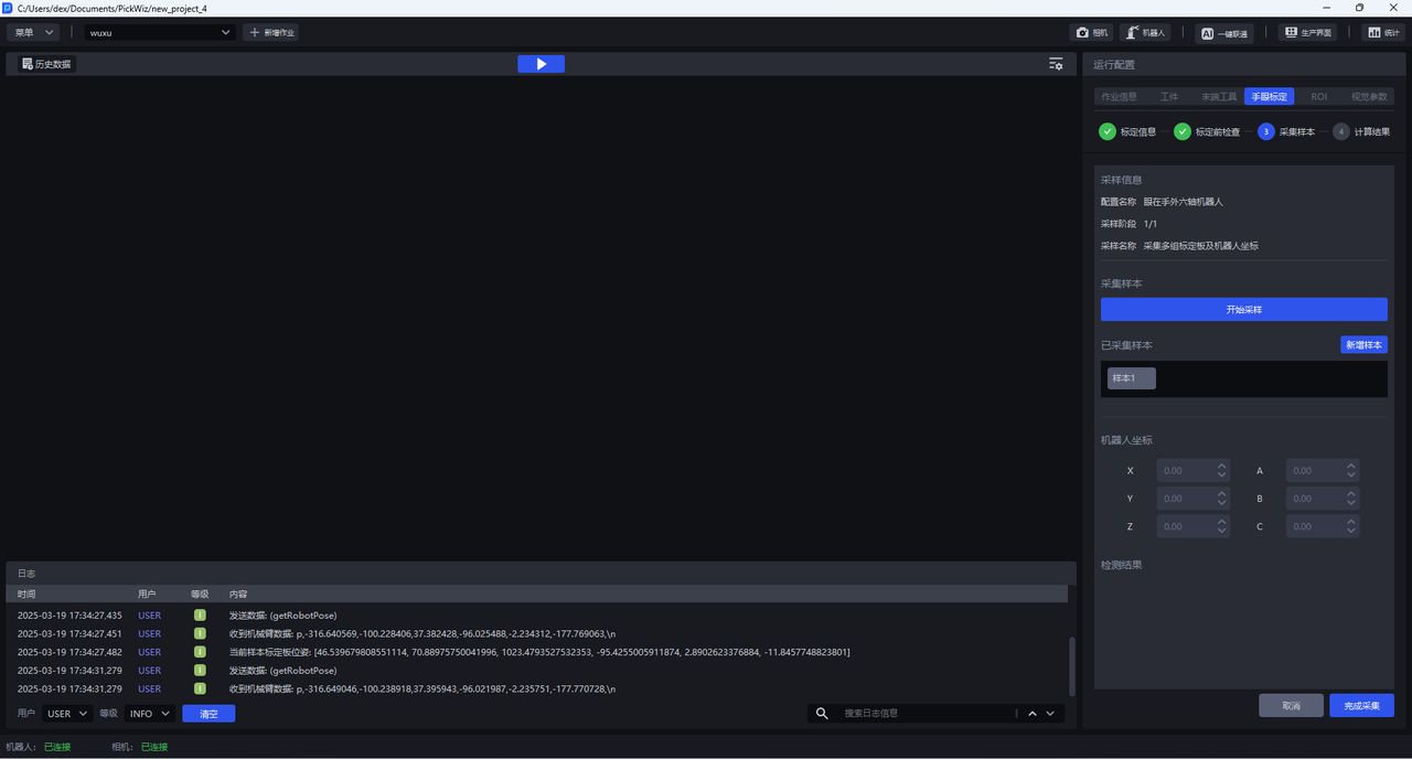
1.4.1 collects multiple sets of Calibration Board and Robot coordinates
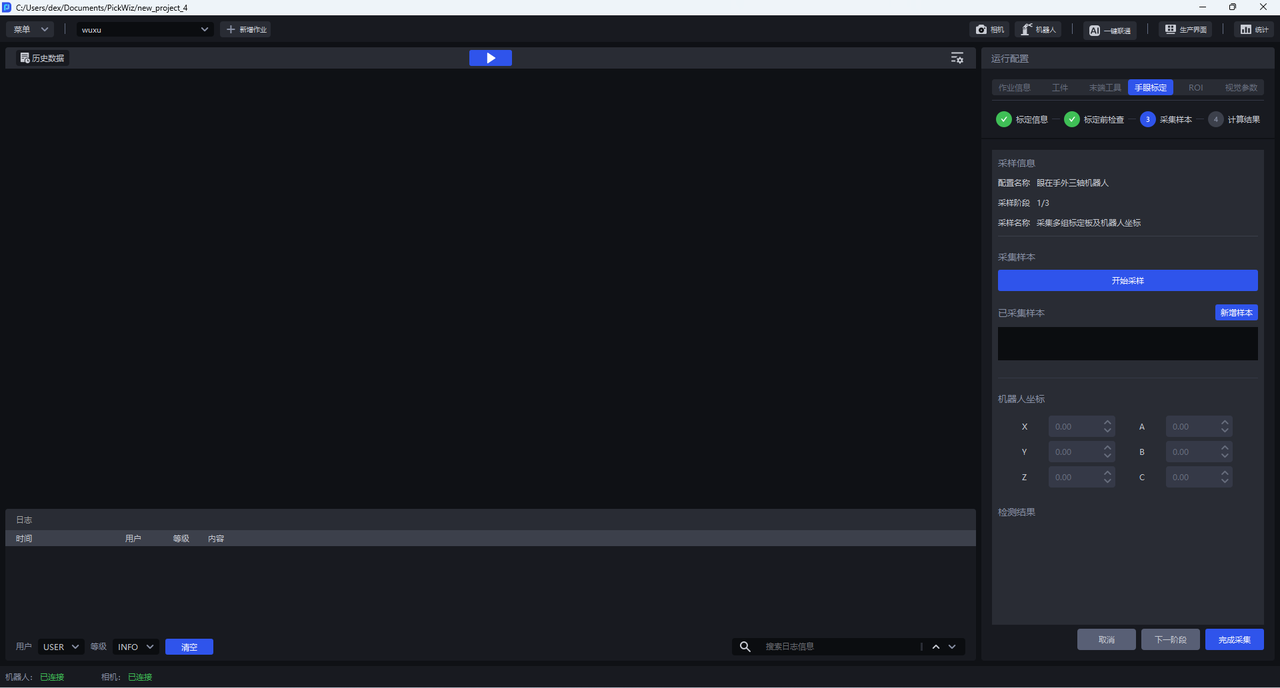
(1) Control the Robot to move the Calibration Board so that the Calibration Board is located in the center of the Camera's field of view and parallel to the Camera's shooting plane.
(2) Click Start Sampling, the Start Sampling button will change to Stop Sampling, and two types of tests, Camera and Robot, will appear in the Detection Result Bar below. The green icons for both Camera and Robot tests indicate that the test has passed. If there is a red icon, it means that it has failed, and it should be checked.
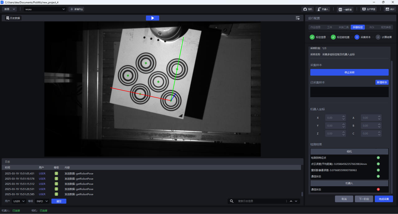
(3) Camera detection is divided into 4 aspects:
(4) Robot detection is divided into three aspects:
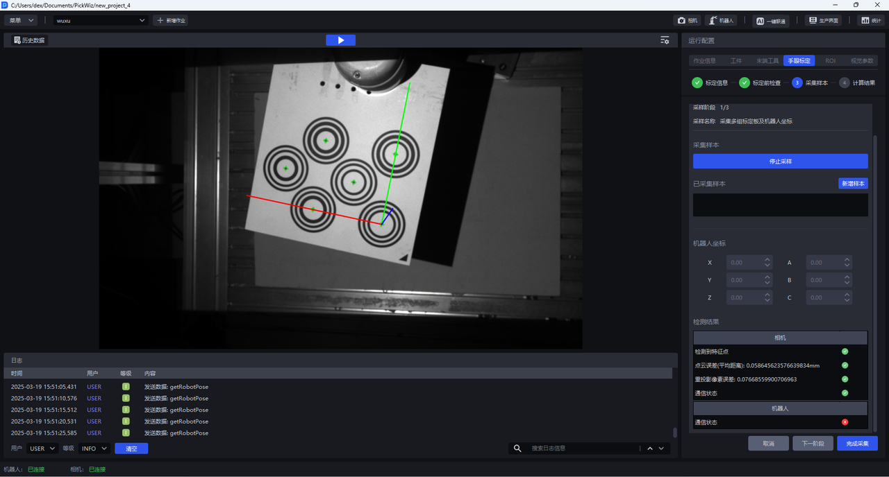
(5) The coordinate axis appears on the Calibration Board in the visualization window. The center of each concentric circle is green, which means that the current posture meets the requirements.
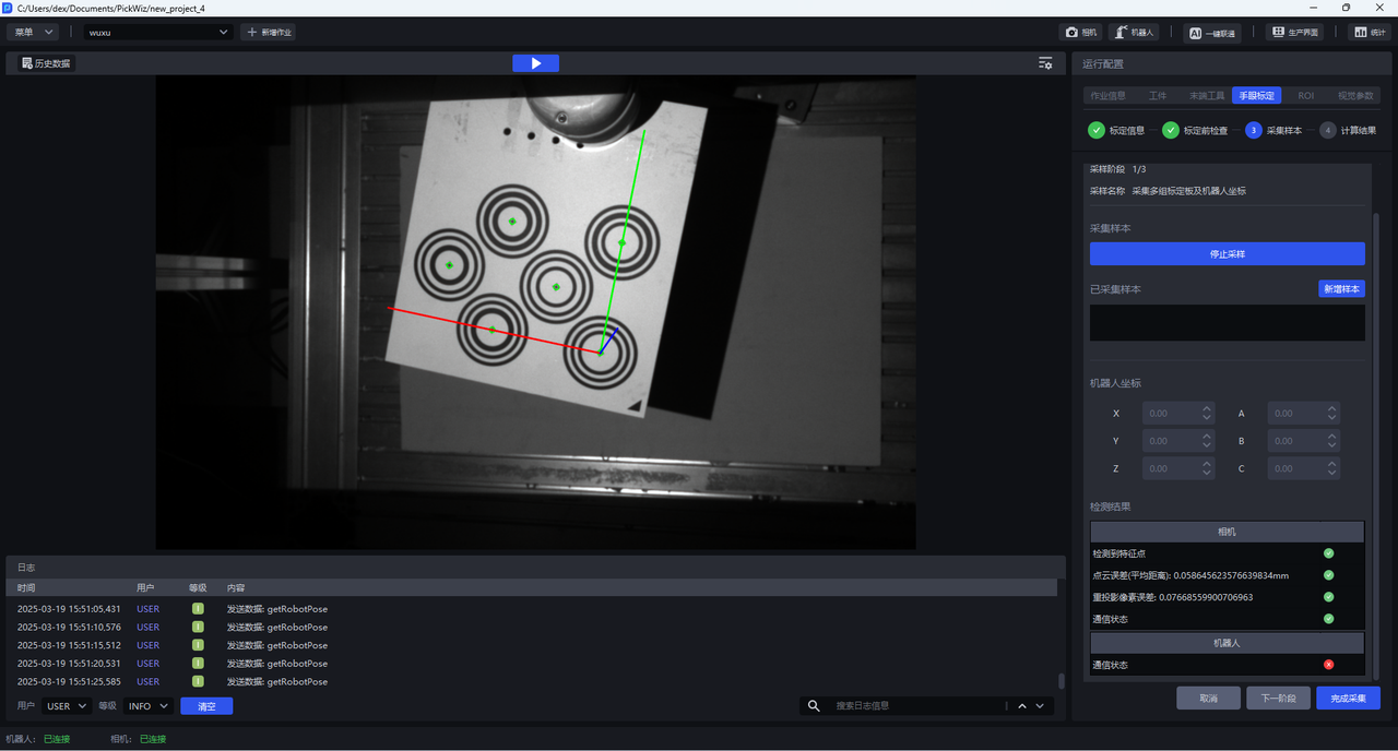
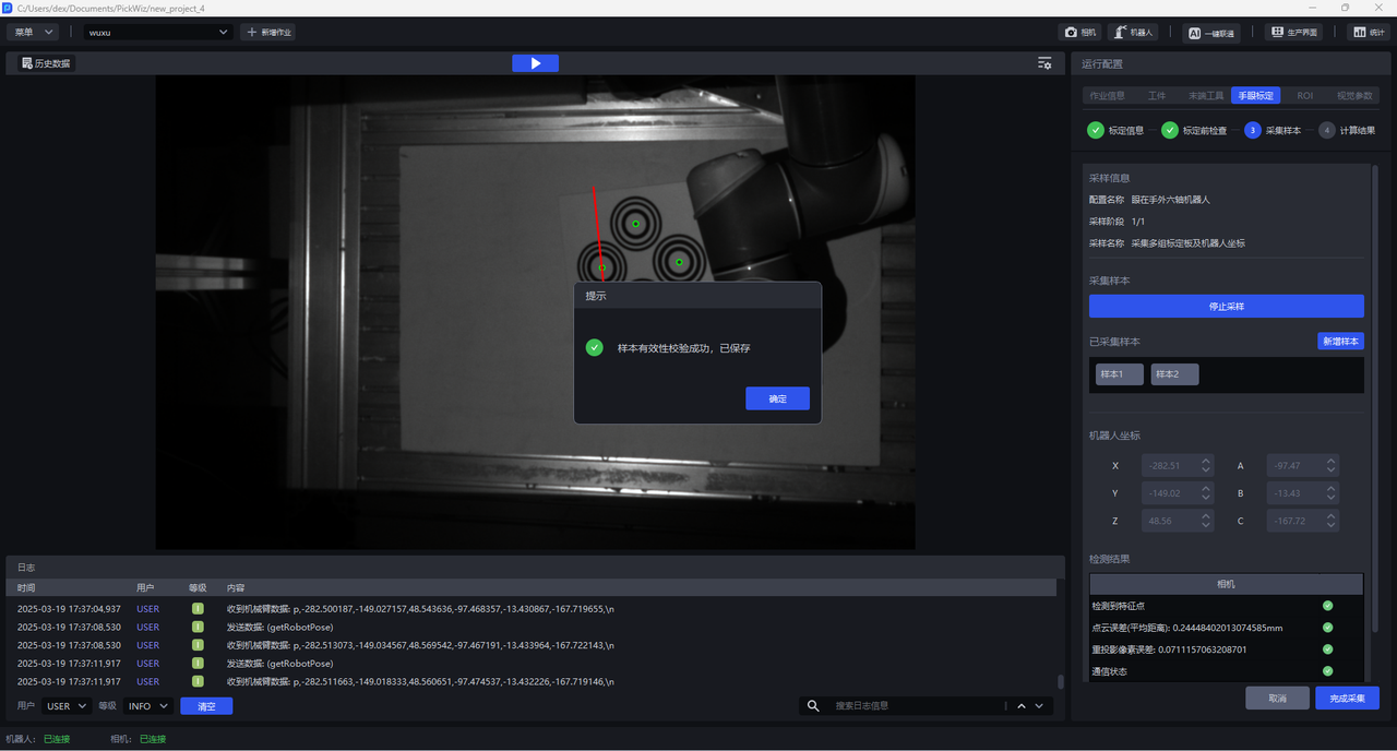
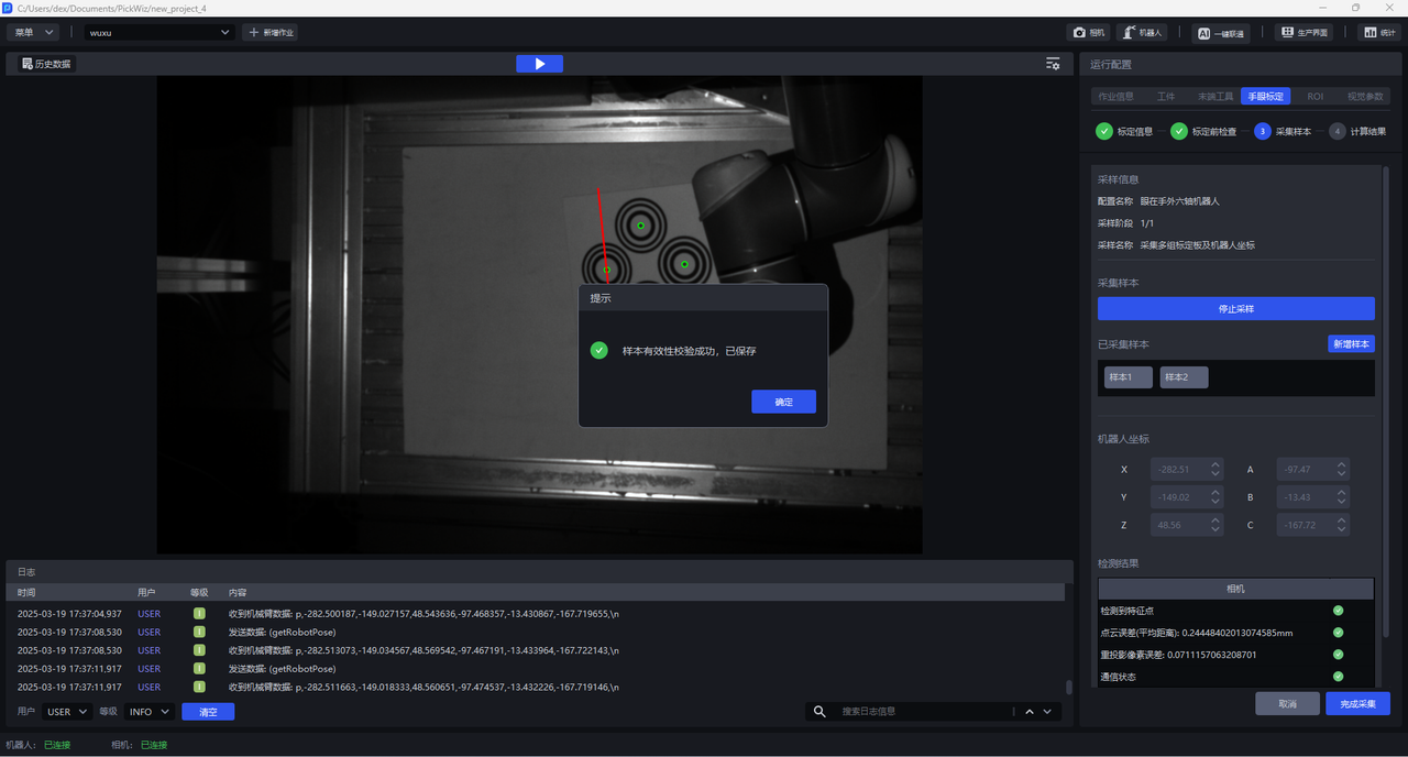
(6) Click Add Sample. If the sample is valid, the Sample Validity Verification Successful pop-up window will appear. After clicking OK, the Sample Collected will appear with the Sample 1 mark. Click Sample 1 to view the saved sample. Click the Close button after Sample 1 to delete the sample.
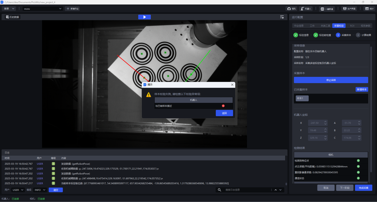
If the sample is close to an existing sample, the sample is invalid, and a 'Sample verification failed' pop-up window will appear, prompting 'Close to an existing sample'. Click 'Return' and control the Robot to move the Calibration Board to collect the sample again.
(7) Control the Robot to move the Calibration Board so that the Calibration Board is located at the four corners of the Camera's field of view, and the rotation angles on the X-axis, Y-axis, and Z-axis are all greater than 10°. Repeat the above steps of collecting samples until at least 5 samples are saved.
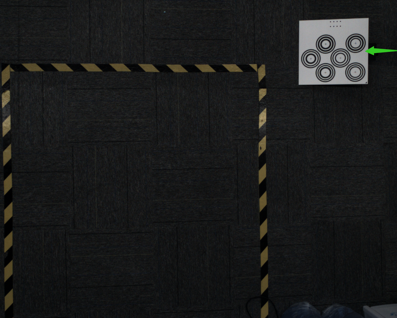
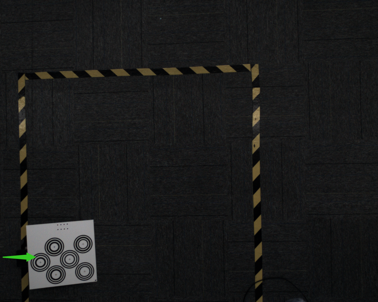
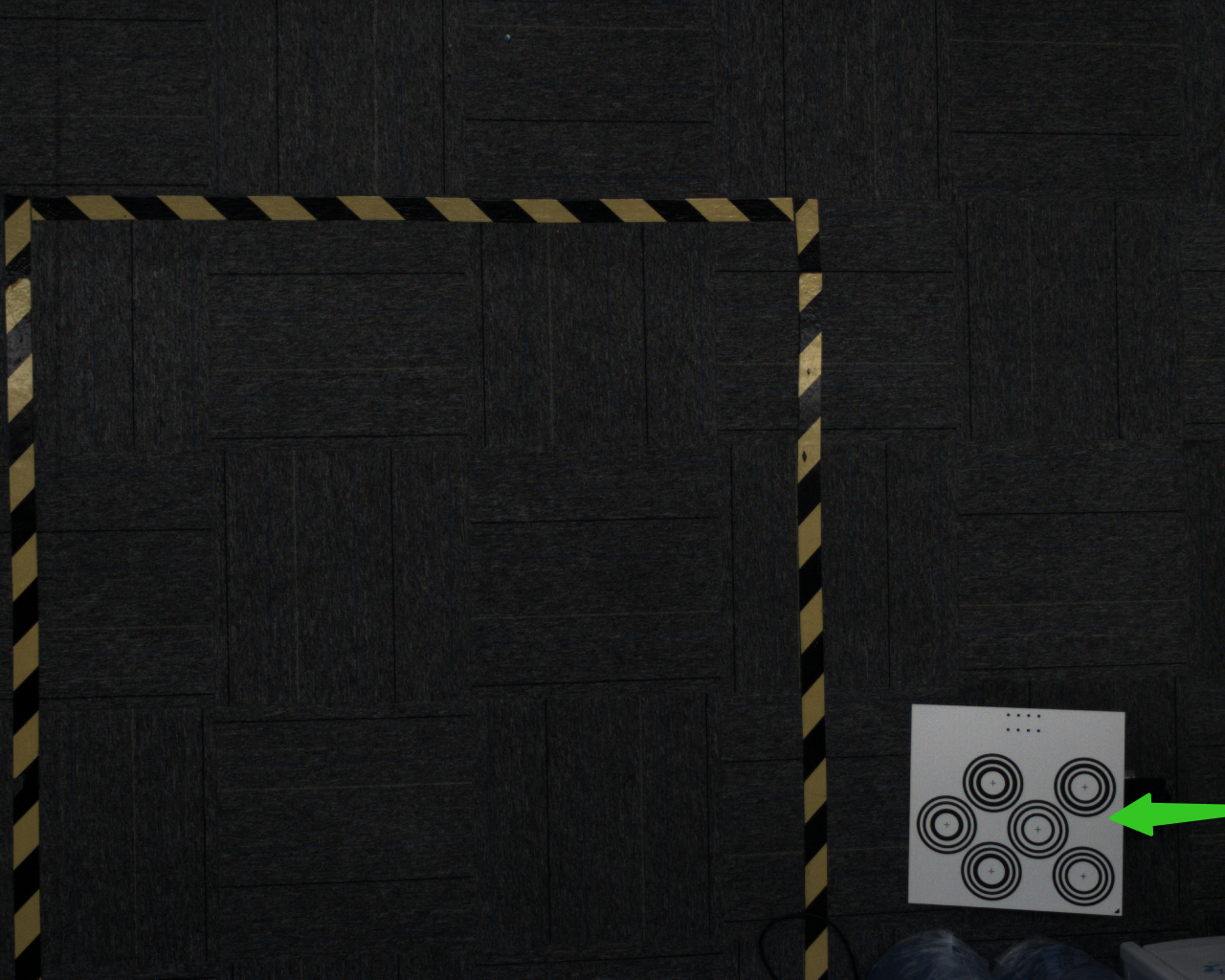
(8) After saving at least 5 valid samples, click Complete Collection to enter the Calculation Results interface.
1.4.2 identifies the Calibration Board to be touched
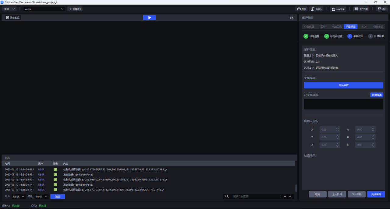
(1) Place the Calibration Board within the camera's field of view and ensure that the Robot with the needle tip installed can touch the Calibration Board.
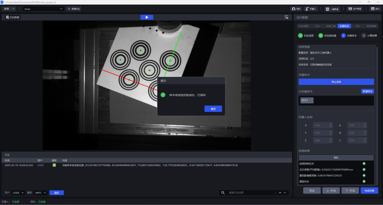
(2) Click Start Sampling until the coordinate axes and feature points appear in the visualization window, and the dots are all green, indicating that the current pose meets the requirements.
(3) Click Add Sample. If the sample is valid, a Save Successful pop-up will appear; if the sample is close to an existing sample, the sample is invalid and a Save Failed pop-up will appear.
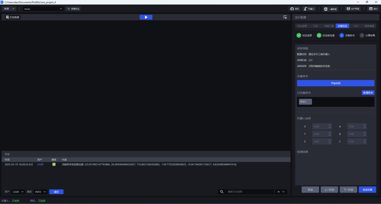
(4) Click Next
1.4.3 Touch Calibration Board
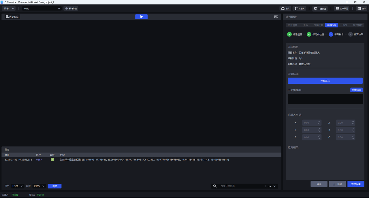
- (1) Click
Start Sampling, control the Robot to move, and follow the numerical order marked in the visualization window, and the needle tips touch the centers of the corresponding concentric circles respectively.
(2) Click Add Sample to collect the Robot coordinates at the time of stamping.
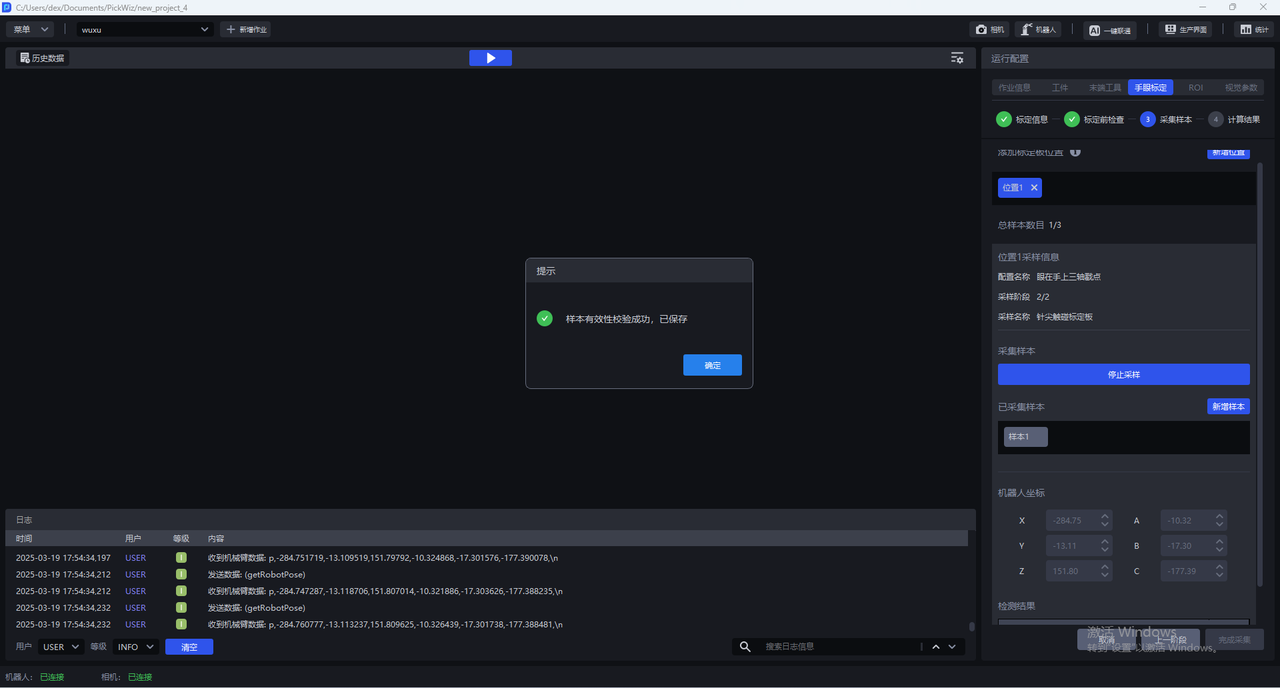
(3) Repeat the above steps to collect at least 3~6 concentric circle poke point samples.
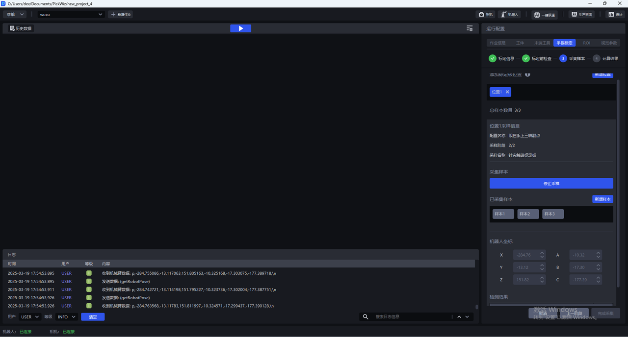
- Click
Next
1.4.4 Calculate calibration results
Click Calculation Result and Pickwiz will calculate the calibration result based on the collected samples. If the calibration error does not meet the requirements, please perform Calibration Result Check and Analysis.
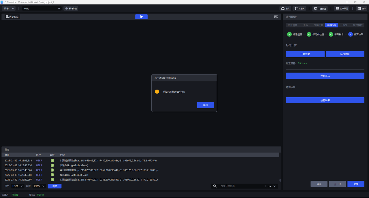
1.5 calibration result inspection and analysis
If the calibration error exceeds the normal range, you need to locate the cause of the error, click Calibration Diagnosis, refer to [Calibration Result Inspection and Analysis] (标定结果检查与分析.md) to analyze the calibration results, solve the problem and check again until the accuracy of the calibration results meets the Scene requirements.
1.6 Select Eye-hand calibration configuration
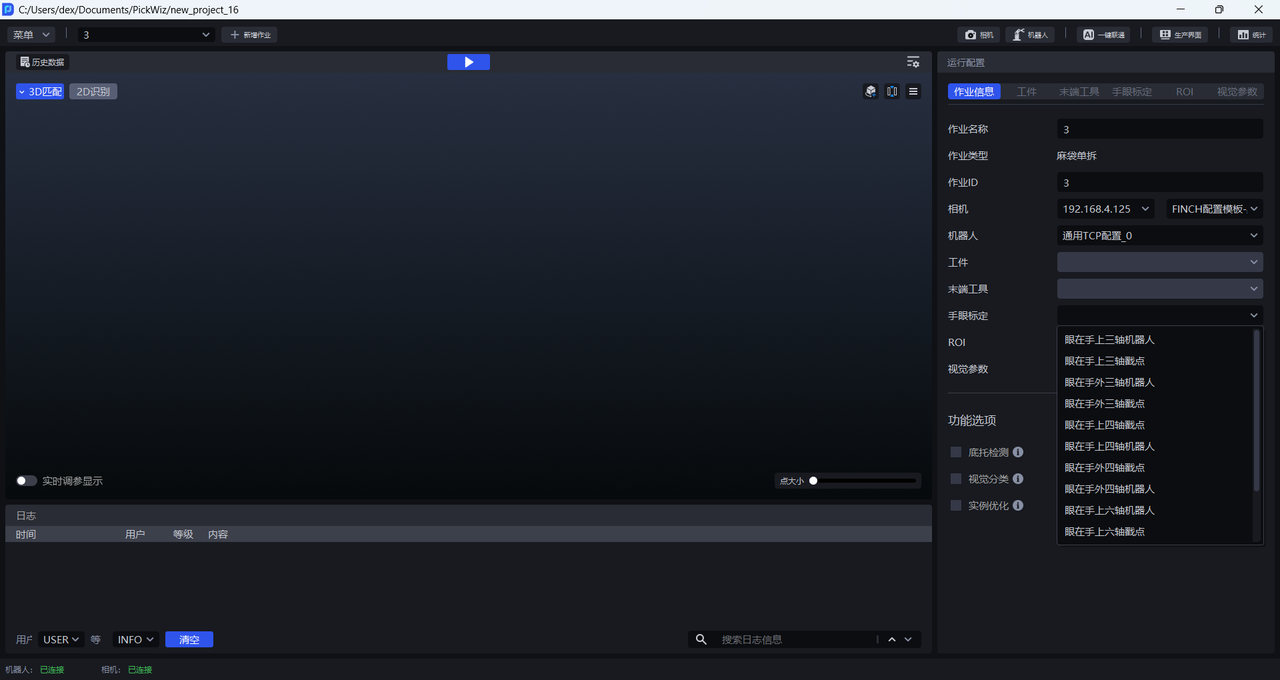
After the calibration process is completed, return to the Run Configuration interface, click Task Information, click the drop-down box of Eye-hand calibration, and select the corresponding Eye-hand calibration configuration.
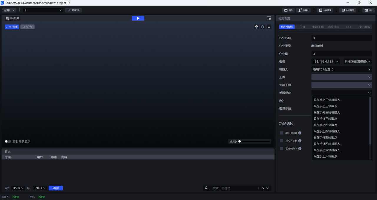
2. Point tool calibration
2.1 Preparation before calibration
Before Eye-hand calibration, the following preparations need to be made:
(1) Complete the hardware construction of the 3D visual guidance kit
Please refer to [3D Vision Guidance Kit Hardware Construction] (../常用操作/3D视觉引导套件硬件搭建.md) to complete the installation and connection of Robot, Camera and industrial computer
(2) Complete the new project and new Task
Please refer to Project Operation Guide and Task Operation Guide to create a new project and Task
(3) Complete the Camera connection and parameter adjustment and configure the Task information
Please refer to [Camera Connection and Parameter Adjustment Guide] (../常用操作/相机连接与调参指南.md) to connect the Camera, adjust the Camera imaging quality, verify the Camera accuracy, and configure the Task information
(4) Complete Robot communication configuration
Please refer to Robot Configuration and Communication Operation Guide to establish communication between Robot and Pickwiz
(5) Prepare materials required for calibration
Please ensure that the Calibration Board is flat and clear, with no obvious scratches or dirt, and no bending or deformation.
Install the needle tip device and fix it on the end of the Robot, and make the corresponding tool coordinate system to verify and confirm that the tool coordinate system is accurate
After TCP calibration is completed, try to move the Robot in the tool coordinate system. For a four-axis Robot, the positive z-axis direction is usually downward along the end of the Robot
You can also observe the calibrated tool coordinate coefficient value. If the needle tip device is installed like the figure below and extends along the center of the flange, the x and y of the TCP should be 0
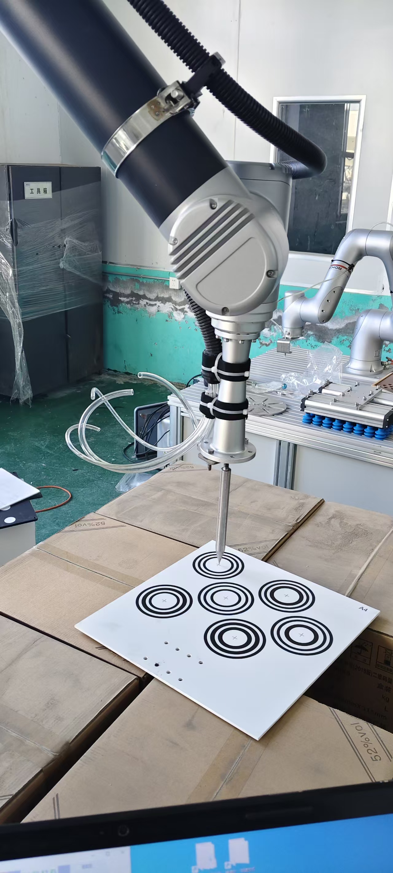
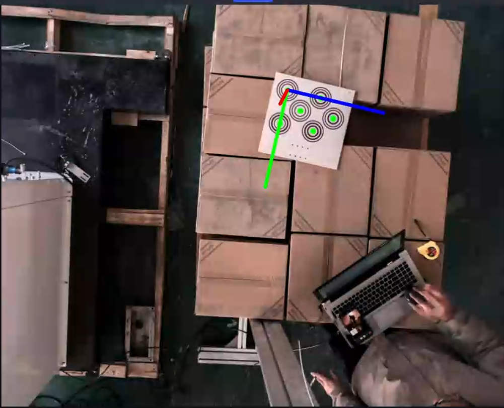
To calibrate the needlepoint tool point, please ensure that the Calibration Board is placed horizontally on the work platform and is within the camera's field of view, such as the picture below.
2.2 calibration information configuration
Enter the Eye-hand calibration interface and click Add Eye-hand calibration to enter the calibration information configuration interface.
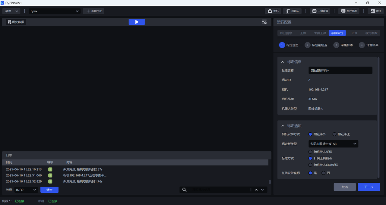
Calibration nameallows you to name the current calibration configuration yourself.Calibration IDis used by Robot to switch calibration configurationsCamerais the IP address of the currently connected CameraCamera Brandis the brand of the currently connected CameraRobot typeis consistent with the Robot type in Robot configuration- If the six-axis Robot is displayed here, you need to go to the Robot configuration to modify it to four-axis, save it, and then return to the Eye-hand calibration configuration to create a new calibration effective * *
Camera installation methodselectEye to handCalibration Board Typeselects the current Calibration Board type
The appropriate Calibration Board is mainly determined by the Robot type and Camera height. Please refer to the following table to select the appropriate Calibration Board according to the actual scene requirements.
| Robot type | Camera installation height | Select Calibration Board |
|---|---|---|
| six-axis Robot | Below 0.5 meters | A6 Multi-Concentric Circle Calibration Board |
| Below 1.5 meters | A5 Multi-Concentric Circle Calibration Board | |
| 1.5 meters -- 2.5 meters | A4 Multi-Concentric Circle Calibration Board | |
| 2.5 meters and above | A3 Multi-Concentric Circle Calibration Board | |
| three-axis/four-axis Robot | Below 0.5 meters | A6 Multi-Concentric Circle Calibration Board |
| Below 1.5 meters | A5 Multi-Concentric Circle Calibration Board | |
| 1.5 meters -- 2.5 meters | A4 Multi-Concentric Circle Calibration Board | |
| 2.5 meters and above | A3 Multi-Concentric Circle Calibration Board |
Calibration methodSelectPoint Tool Poke Point CalibrationIf the Robot has written a corresponding calibration program, and when sampling the Calibration Board, the Robot needs to run the calibration program and send the pose to PickWiz, then
Get coordinates online** selectYes; if the Robot has not written a corresponding calibration program, and when sampling the Calibration Board, you need to manually enter the pose of the RobotEnd-effector, thenGet the coordinates online**SelectNo.
2.3 Inspection before calibration
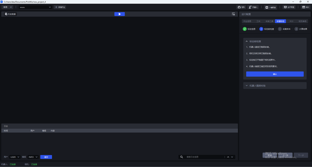
Make sure the Robot base is firmly installed
Before performing eye-hand calibration, you should carefully check the installation of the Robot base. If the Robot base is not firmly installed, the Robot will shake significantly when it moves, affecting the Robot's accuracy and thus the calibration results.
Follow the steps below to check whether the installation of the Robot base meets the requirements:
First, the surface on which the Robot base is installed must be flat and clean;
Second, control the Robot to translate or rotate at a large speed at 100% speed, and observe whether there are signs of shaking in the Robot. If there is any shaking, please readjust the fixed Robot base to ensure that problems such as displacement and tilt do not occur when the Robot moves;
Third, check whether the Robot body and the base are tightly connected, and tighten the screws to prevent them from loosening.
Make sure the Camera and its bracket are securely installed
Before performing eye-hand calibration, you should carefully check the installation of the Camera and its bracket. If the Camera and its bracket are not firmly installed, it will affect the camera imaging quality and thus the calibration results.
Follow the steps below to check whether the installation of the Camera and its bracket meets the requirements:
First, check whether the Camera bracket is a machine-mounted Target. The material of the bracket should avoid aluminum profiles;
Second, shake the bracket and observe whether there is obvious shaking in the bracket. If there is any shaking, please readjust the fixed bracket;
Third, shake the Camera and observe whether there is obvious shaking in the Camera to ensure that the Camera is installed securely.
Make sure the Calibration Board is placed smoothly in the Camera's field of view
- The camera installation method is Eye to hand, and the Calibration Board needs to be placed at a possible location for incoming materials to ensure that the Calibration Board is within the Camera's field of view.
Ensure that Robot accuracy meets project usage requirements
- If the Robot accuracy does not meet the project usage requirements, please refer to [Calibration Verification] (标定校验.md) to correct the Robot accuracy.
Ensure that the tool coordinate system of the poking device meets the accuracy requirements
- TCP accuracy can be verified using tip-to-tip rotation angle in the tool coordinate system
2.4 Collect Sample
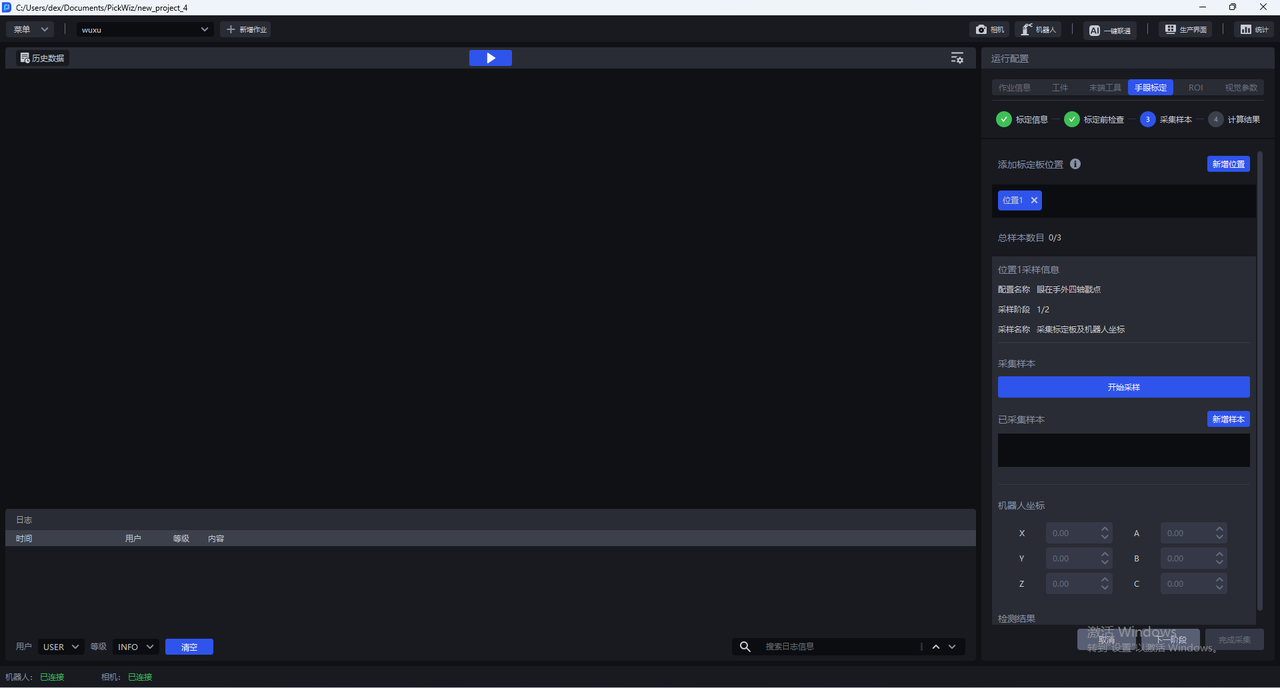
2.4.1 collects Calibration Board and Robot coordinates
(1) Adjust the position of the Calibration Board, place it in the area where the Target is placed, and click Start Sampling.
(2) Click Add Sample. If the sample is valid, a message Save Successfully will pop up; if the sample is close to an existing sample, the sample is invalid and a message indicating failed saving will pop up.
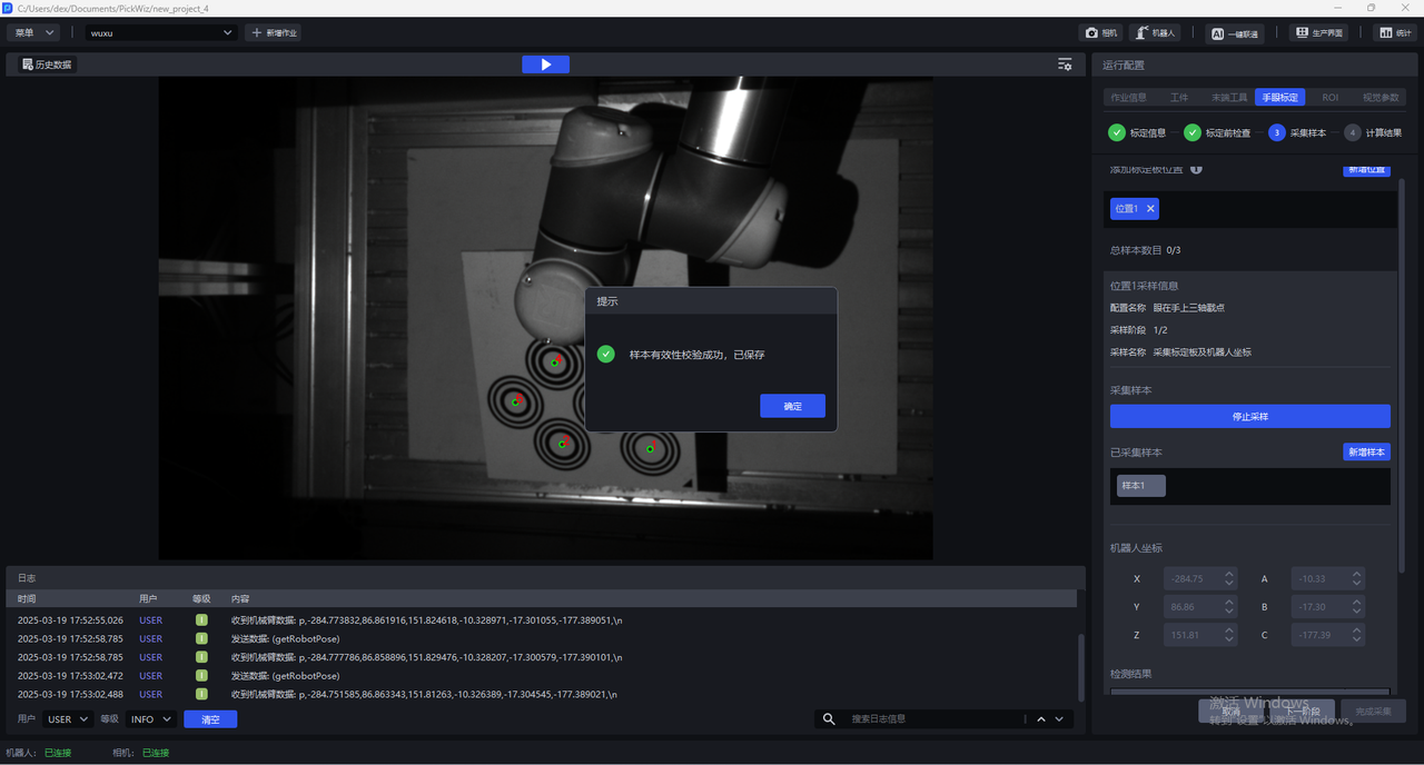
(3) Test results. If each test item is a green icon, the coordinate axis and feature points appear in the visualization window, and the center of the circle is green, it means that the current posture meets the requirements.
The detection is divided into 4 aspects:
2.4.2 Tip Touch Calibration Board
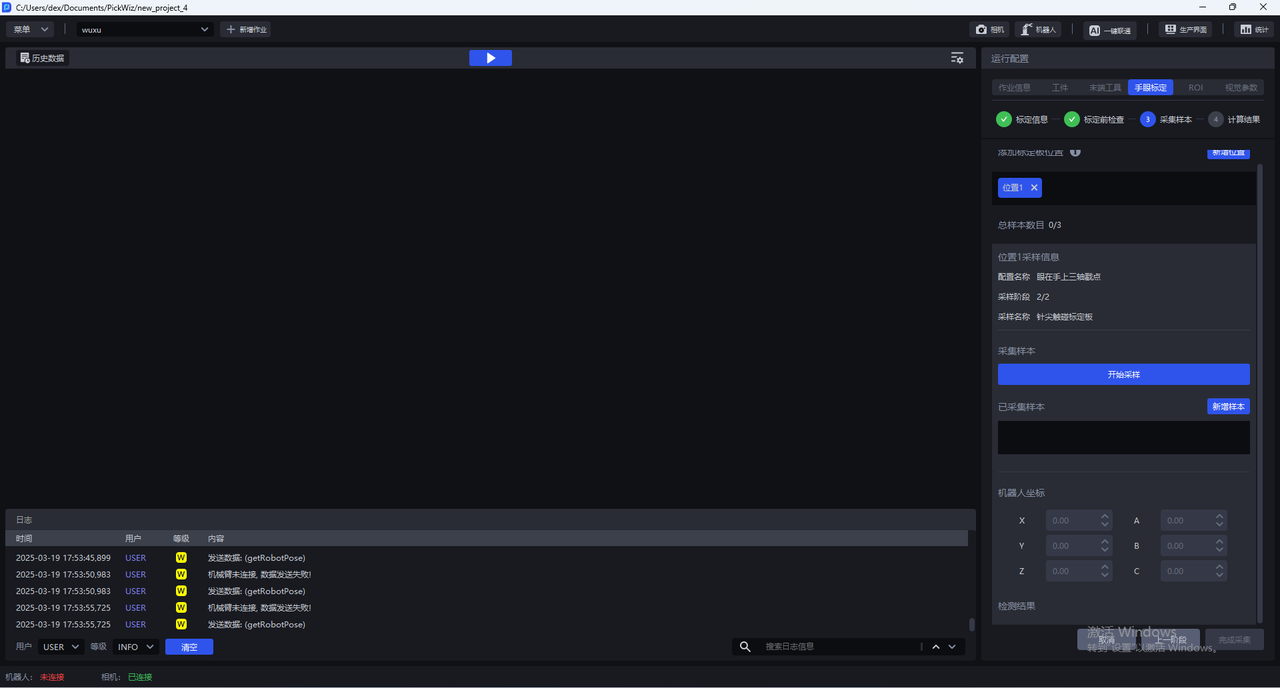
(1) Click Start Sampling, control the Robot to move, and follow the numerical order marked in the visualization window, and the needle tips touch the centers of the corresponding concentric circles respectively.
(2) Click Add Sample to collect the Robot coordinates at the time of stamping.
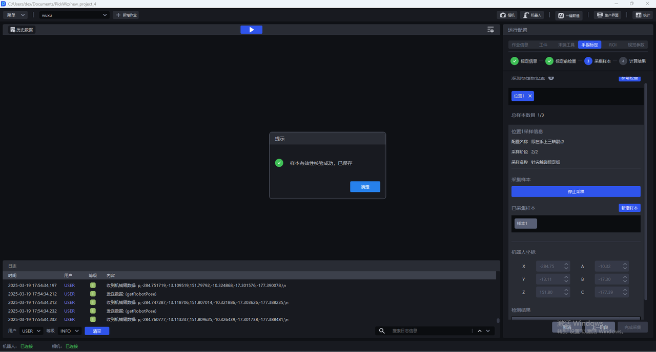
(3) Repeat the above steps to collect at least 3~6 concentric circle poke point samples.
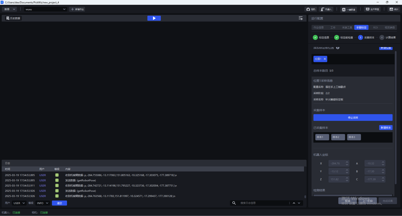
- Click
Next
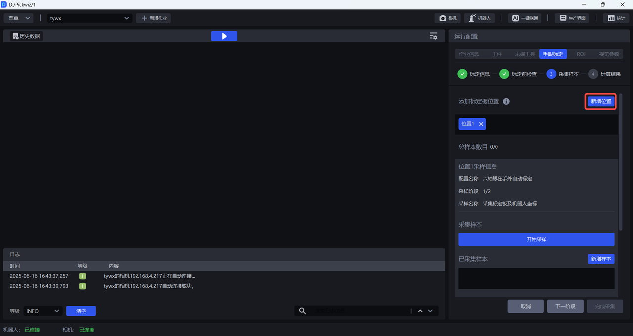
2.4.3 [Optional] Add new calibration position
In the calibration sampling phase, the system defaults to a single attitude calibration mode, but it can be expanded to a multi-position calibration strategy in specific application scenes, which improves the calibration robustness and system adaptability under complex working conditions:
To address the problem of accuracy deviation caused by changes in depth of field in wide-angle vision systems, layered sampling in the Z-axis direction can effectively balance the error distribution of different focal planes;
For working environments with limited space, when a single Calibration Board deployment cannot complete the collection of more than 3 feature points, the Calibration Board can be deployed in multiple locations and sampled in batches to meet the minimum sample size requirements through accumulation.
Click Add Position to add a calibration position, repeat **2.4.1 to collect Calibration Board and Robot coordinates ** and **2.4.2, touch the Calibration Board ** with the tip of the needle to collect the calibration sample and poke the Calibration Board.
2.4.4 Calculate calibration results
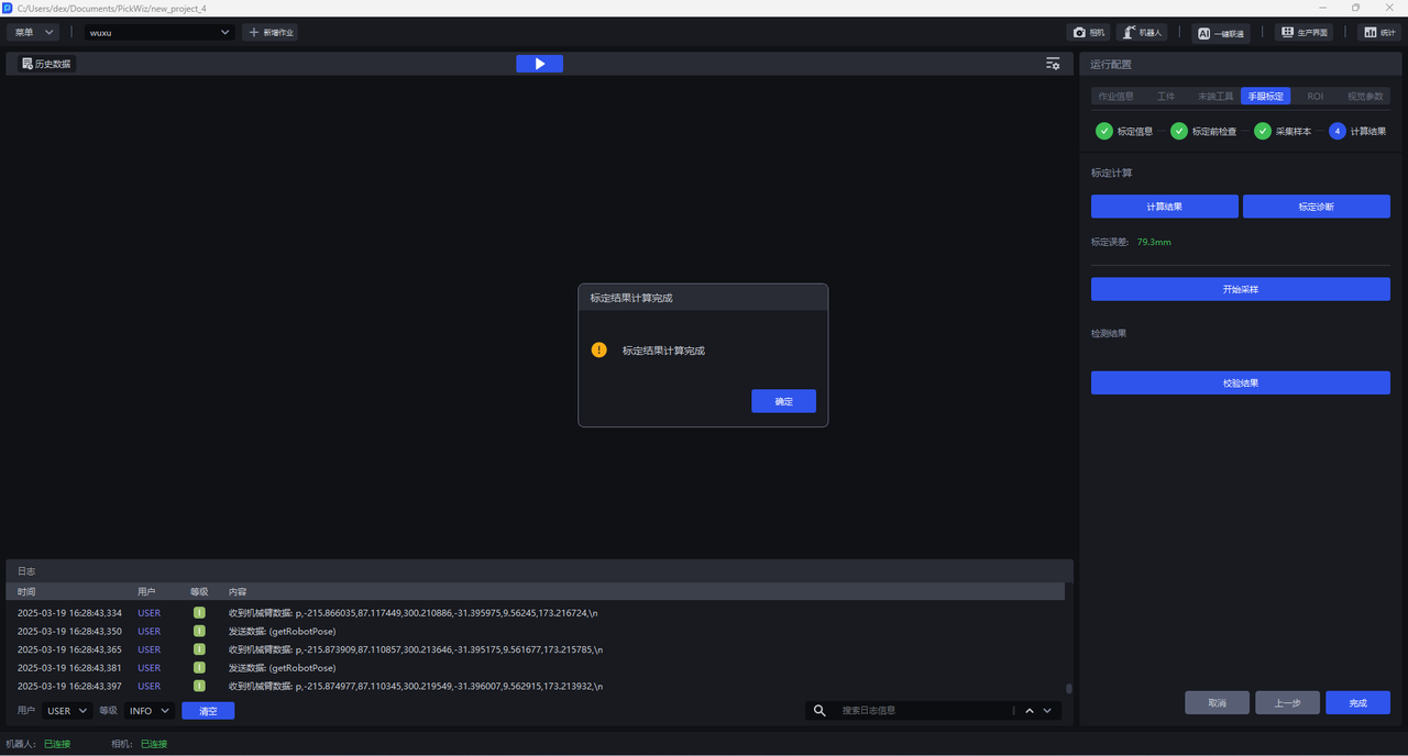
Click Calculation Result and Pickwiz will calculate the calibration result based on the collected samples. If the calibration error does not meet the requirements, please perform Calibration Result Check and Analysis.
2.5 calibration result inspection and analysis
If the calibration error exceeds the normal range, you need to locate the cause of the error, click Calibration Diagnosis, refer to [Calibration Result Inspection and Analysis] (标定结果检查与分析.md) to analyze the calibration results, solve the problem and check again until the accuracy of the calibration results meets the Scene requirements.
2.6 Select Eye-hand calibration configuration
After the calibration process is completed, return to the Run Configuration interface, click Task Information, click the drop-down box of Eye-hand calibration, and select the corresponding Eye-hand calibration configuration.