Eye-hand calibration operation guide
The "hand" is Robot, and the "eye" is 3DCamera. Eye-hand calibration aims to determine the correspondence between the Camera coordinate system and the Robot coordinate system, helping Pickwiz to accurately convert the pose information in the Camera coordinate system into the spatial coordinate information required for Robot movement, thereby achieving accurate vision-guided grabbing and placement.
The process of eye-hand calibration is as follows:

Preparation before calibration: Prepare the required materials and conditions for Eye-hand calibration;
Calibration information configuration: Select Eye-hand calibration configuration according to Camera installation method, calibration method, etc.;
Pre-calibration inspection: Check whether the Robot, Calibration Board, etc. have been installed and meet the calibration requirements;
Collect samples: Take photos to collect Calibration Board samples;
Inspection and analysis of calibration results: Inspect and analyze the results to determine whether the calibration accuracy meets actual needs;
Select calibration configuration: Select the corresponding calibration configuration for TaskScene.
Please refer to this operation guide to perform Eye-hand calibration of Camera and Robot. In addition, you need to perform Eye-hand calibration again when the following situations occur:
The position changes between the Camera and the Robot base** (EyeToHand)** or the Camera and the Robot end flange** (EyeInHand)**;
Change other Camera;
Replace with another Robot.
1. Preparation before calibration
Before Eye-hand calibration, the following preparations need to be made:
(1) Complete the hardware construction of the 3D visual guidance kit
Please complete the installation and connection of Robot, Camera and industrial computer first.
(2) Complete the new project and new Task
Please refer to Project Operation Guide and Task Operation Guide to create new projects and tasks to meet actual Scene needs.
(3) Complete Camera connection and parameter adjustment
Please refer to [Camera Connection and Parameter Adjustment Guide] (../常用操作/相机连接与调参指南.md) to connect the Camera, adjust the Camera imaging quality, and verify the Camera accuracy
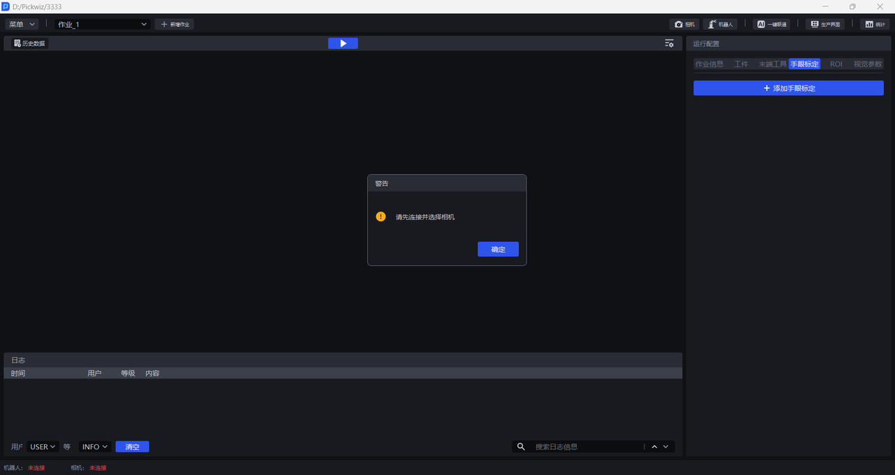
(4) Complete Robot communication configuration
Please refer to Robot Configuration and Communication Operation Guide to establish communication between Robot and Pickwiz
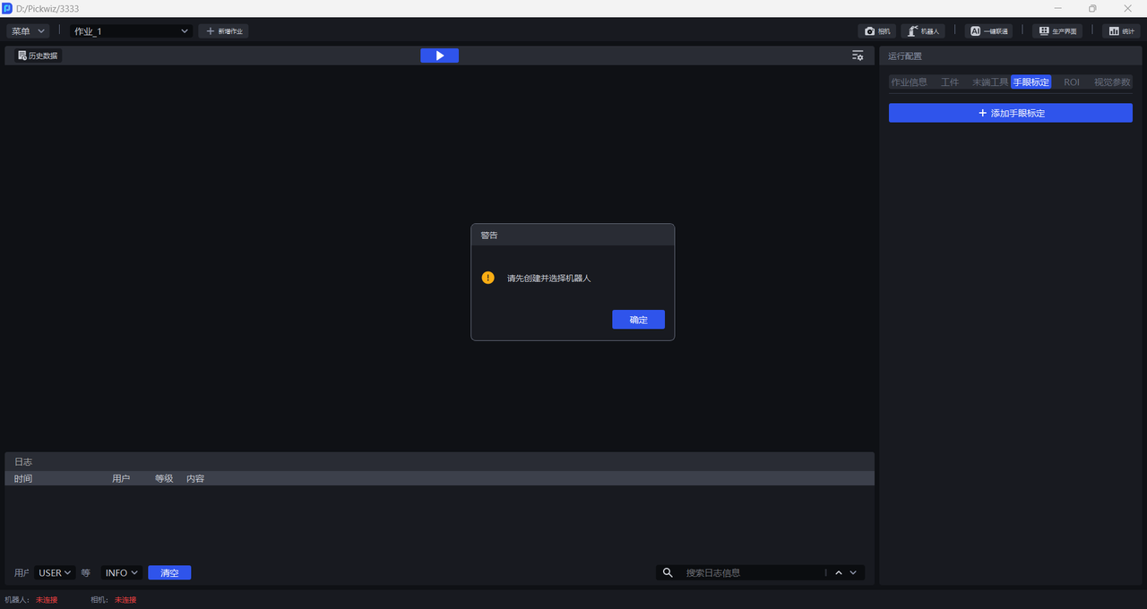
(5) Prepare materials required for calibration
Please ensure that the Calibration Board is flat and clear, with no obvious scratches or dirt, and no bending or deformation.
If the Camera is installed outside the robot arm and the Calibration Board needs to be installed on the RobotEnd-effector, please ensure that the Calibration Board is installed securely and is within the Camera's field of view.
First install the Calibration Board connector to the Robot end flange, and then install the Calibration Board to the connector. If a non-removable clamp is installed on the end flange of the Robot, the Calibration Board can be mounted directly to the clamp.
If the calibration method uses a needle point tool for calibration, please ensure that the needle tip shape is complete and not deformed. The needle point tool needs to be installed on the Robot. The needle point tool can be installed on the end flange or fixture of the Robot.
2. Calibration information configuration
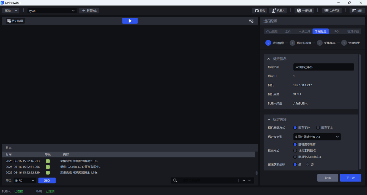
Calibration nameallows you to name the current calibration configuration yourself.Calibration IDis used by Robot to switch calibration configurationsCamerais the IP address of the currently connected CameraCamera Brandis the brand of the currently connected CameraRobot typeis consistent with the Robot type in Robot configuration
Eye-hand calibration needs to determine the precise position and direction of the Camera in the Robot coordinate system, so the Camera type, Camera installation method, Robot type, and data collection method will all affect the specific calibration method and process;
Before collecting samples, you need to configure the Camera installation method, Calibration Board type, Calibration method, and Online acquisition of coordinates. The configured Eye-hand calibration cannot be modified. If the configuration is wrong, you can delete the calibration and then add it.
2.1 Camera installation method
- Eye in hand (EyeInHand): Camera is fixedly installed on the End-effector of the robot arm and moves with the movement of the robot arm. The Camera is fixed relative to the Robot end flange, and the Calibration Board is fixed relative to the Robot base.
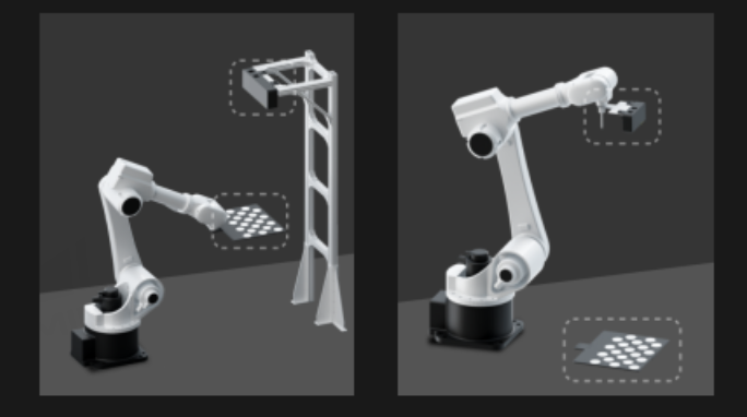
The camera is fixedly installed on the end-effector of the robot arm. The robot type is a three-axis robot. For the calibration process, please refer to [Eye in hand three-axis robot calibration] (眼在手上三轴机器人标定.md)
Camera is fixedly mounted on the end-effector of the robot arm, and the robot type is quad-axis robot. For the calibration process, refer to [Eye in hand quad-axis robot calibration] (眼在手上四轴机器人标定.md)
The camera is fixedly installed on the end-effector of the robot arm. The robot type is a six-axis robot. For the calibration process, please refer to [Eye in hand six-axis robot calibration] (眼在手上六轴机器人标定.md)
- Eye to hand (EyeToHand): The Camera is fixedly installed on the outside of the robot arm and does not move with the movement of the robot arm. The Camera is fixed relative to the Robot base, and the Calibration Board is fixed relative to the Robot end flange.
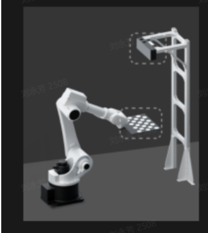
The camera is fixedly installed on the outside of the robot arm. The robot type is a three-axis robot. For the calibration process, please refer to [Eye to hand three-axis robot calibration] (眼在手外三轴机器人标定.md)
The camera is fixedly installed on the outside of the robot arm. The robot type is a four-axis robot. For the calibration process, please refer to [Eye to hand four-axis robot calibration] (眼在手外四轴机器人标定.md)
The camera is fixedly installed on the outside of the robot arm. The robot type is a six-axis robot. For the calibration process, please refer to [Eye to hand six-axis robot calibration] (眼在手外六轴机器人标定.md)
2.2 Calibration Board type
Choosing the appropriate Calibration Board affects the ease of use of the calibration process and the accuracy of the calibration results, and is one of the keys to successful eye-hand calibration. The existing Calibration Board of Dexforce is as follows. Calibration Board drawings can be downloaded and printed.
| Robot type | Camera installation height | Select Calibration Board |
|---|---|---|
| six-axis Robot | Below 0.5 meters | A6 Multi-Concentric Circle Calibration Board |
| Below 1.5 meters | A5 Multi-Concentric Circle Calibration Board | |
| 1.5 meters -- 2.5 meters | A4 Multi-Concentric Circle Calibration Board | |
| 2.5 meters and above | A3 Multi-Concentric Circle Calibration Board | |
| three-axis/four-axis Robot | Below 0.5 meters | A6 Multi-Concentric Circle Calibration Board |
| Below 1.5 meters | A5 Multi-Concentric Circle Calibration Board | |
| 1.5 meters -- 2.5 meters | A4 Multi-Concentric Circle Calibration Board | |
| 2.5 meters and above | A3 Multi-Concentric Circle Calibration Board |
2.3 calibration method
Random posture sampling calibration: randomly move the Robot's End-effector, collect Calibration Board samples at multiple locations, identify feature points on the Calibration Board, and collect the random posture of the End-effector.
Needlepoint tool poke point calibration: Install the needlepoint tool on the end flange of the Robot, place the Calibration Board on the work platform, make the needlepoint tool perpendicular to the Calibration Board, and let the needlepoint tool touch different dots on the Calibration Board.
The needlepoint tool poke point calibration is suitable for situations where the robot activity space is limited and the Calibration Board cannot be installed. This method is recommended for 3-axis and 4-axis Robots.
- Random posture automatic sampling: Compared with "random posture sampling", this calibration method supports setting a movement range, and the system automatically calculates random movement points within the range. Then the Robot moves based on the points, collects Calibration Board samples at multiple locations, identifies feature points on the Calibration Board, and collects random postures of the End-effector. The calibration process is faster and the interaction is simpler.
2.4 Get coordinates online
If the Robot has written a corresponding calibration program, when sampling the Calibration Board, the Robot will run the calibration program and automatically send the pose to PickWiz. **Get coordinates online **Select Yes. If you need to write your own calibration program, please refer to Robot Program Collection
If the Robot does not write a corresponding calibration program, you need to manually enter the pose of the RobotEnd-effector when sampling the Calibration Board. **Get coordinates online **Select No.
3. Inspection before calibration
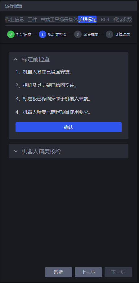
- Make sure the Robot base is firmly installed
Before performing eye-hand calibration, you should carefully check the installation of the Robot base. If the Robot base is not firmly installed, the Robot will shake significantly when it moves, affecting the Robot's accuracy and thus the calibration results.
Follow the steps below to check whether the installation of the Robot base meets the requirements:
First, the surface on which the Robot base is installed must be flat and clean;
Second, control the Robot to translate or rotate at a large speed at 100% speed, and observe whether there are signs of shaking in the Robot. If there is any shaking, please readjust the fixed Robot base to ensure that problems such as displacement and tilt do not occur when the Robot moves;
Third, check whether the Robot body and the base are tightly connected, and tighten the screws to prevent them from loosening.
- Make sure the Camera and its bracket are securely installed
Before performing eye-hand calibration, you should carefully check the installation of the Camera and its bracket. If the Camera and its bracket are not firmly installed, it will affect the camera imaging quality and thus the calibration results.
Follow the steps below to check whether the installation of the Camera and its bracket meets the requirements:
First, check whether the Camera bracket is a machine-mounted Target. The material of the bracket should avoid aluminum profiles;
Second, manually shake the bracket and observe whether there is obvious shaking in the bracket. If there is any shaking, please readjust the fixed bracket;
Third, move the sliding parts on the bracket to observe whether there is obvious shaking. At the same time, test the repeat positioning accuracy to ensure that the repeat positioning accuracy meets the actual scene requirements;
Fourth, shake the Camera and observe whether there is obvious shaking in the Camera to ensure that the Camera is installed securely.
- Make sure the Calibration Board is in place
If the Camera installation method is Eye to hand and the Camera is fixedly installed on the outside of the robot arm, the Calibration Board should be installed at the end of the Robot. Shake the Calibration Board and check whether there is obvious shaking on the Calibration Board. If there is any shaking, please tighten the screws to adjust and fix the Calibration Board.
If the Camera installation method is Eye in hand and the Camera is fixedly installed on the end-effector of the robotic arm, there is no need to install the Calibration Board. The Calibration Board should be placed flat on the working surface and ensure that the Calibration Board is in the camera's field of view and covers the area where the Target is located.
If the calibration method is to use a needle-point tool to poke points on the Calibration Board, the Calibration Board should be fixed on the work platform to prevent the Calibration Board from being displaced when the needle-point tool pokes points on the Calibration Board.
- Ensure that Robot accuracy meets project usage requirements
If the Robot accuracy does not meet the project usage requirements, please refer to [Calibration Verification] (标定校验.md) to correct the Robot accuracy.
4. Collect samples
Choose different calibration processes according to different Camera installation methods and Robot types.
| Camera installation method | Robot type | Calibration process |
|---|---|---|
| Eye in hand | Three-axis Robot | Eye in hand three-axis Robot calibration |
| Eye in hand | Four-axis Robot | Eye in hand four-axis Robot calibration |
| Eye in hand | Six-axis Robot | Eye in hand six-axis Robot calibration |
| Eye to hand | Three-axis Robot | Eye to hand three-axis Robot calibration |
| Eye to hand | Four-axis Robot | Eye to hand four-axis Robot calibration |
| Eye to hand | Six-axis Robot | Eye to hand six-axis Robot calibration |
5. Inspection and analysis of calibration results
The accuracy of the eye-hand calibration results is one of the important factors that affects the robot's grasping accuracy. Therefore, after the calibration is completed, the calibration results need to be checked to determine whether the accuracy of the calibration results can meet the actual scene requirements. If the calibration error exceeds the normal range, you need to locate the cause of the error. Please refer to [Calibration Result Inspection and Analysis] (标定结果检查与分析.md) to analyze the calibration results, solve the problem and check again until the accuracy of the calibration results meets the scene requirements.
6. Select calibration configuration
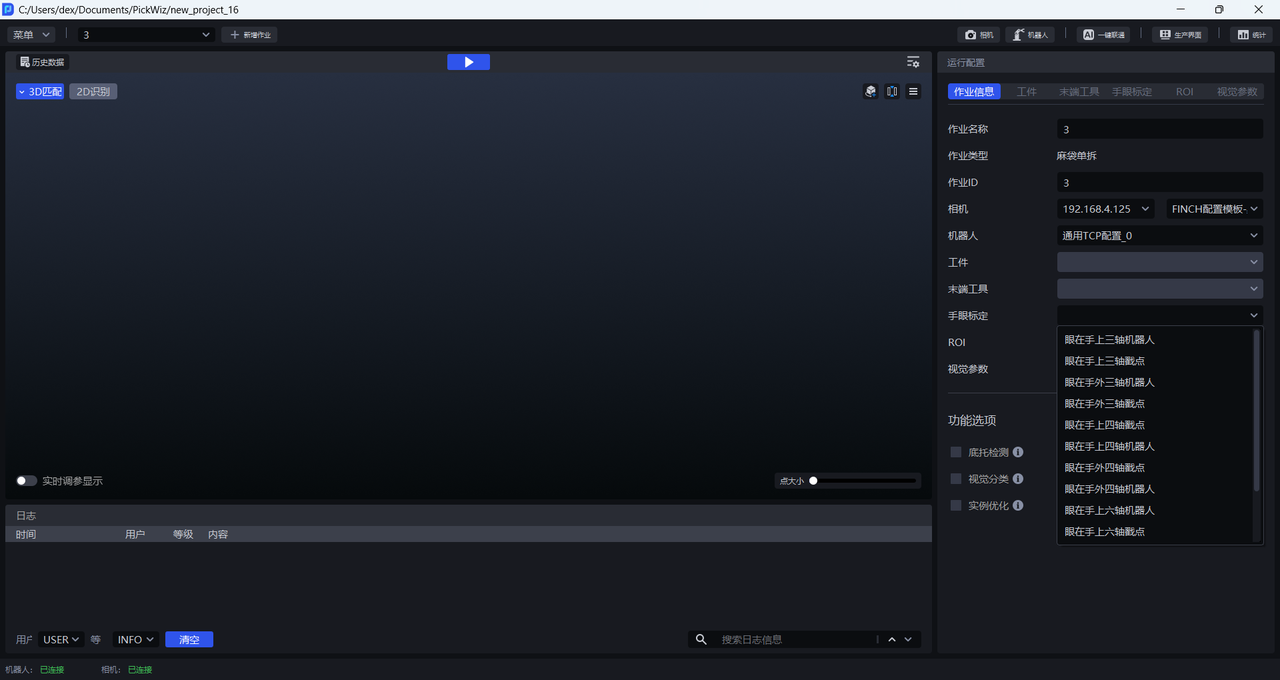
After the calibration process is completed, return to the Run Configuration interface, click Task Information, click the drop-down box of Eye-hand calibration, and select the corresponding Eye-hand calibration configuration.
7. Appendix
7.1 Terms and Concepts
**CameraIntrinsic Parameter: **Camera Intrinsic Parameter is the basic Parameter inside Camera, including lens focal length, principal point coordinates, distortion coefficient, etc., which reflects the internal imaging characteristics of Camera. Among them, the focal length represents the optical characteristics of the Camera lens, the principal point coordinates are the center position of the 2D image, and the distortion coefficient is used to correct various distortions generated during the Camera imaging process. CameraIntrinsic Parameter is used to describe the relationship between the pixel coordinate system and the Camera coordinate system. Generally, the Intrinsic Parameter has been calibrated when the Camera leaves the factory and is stored inside the Camera.
**CameraExtrinsic Parameter:**Camera Extrinsic Parameter reflects the position and orientation of Camera in external space, including two Parameters: rotation matrix and translation vector. The rotation matrix describes the rotation relationship of the Camera coordinate system relative to the world coordinate system. It consists of three rotation angles (such as rotation angles around the x, y, and z axes) and is used to represent the posture of the Camera; the translation vector represents the position of the origin of the Camera coordinate system in the world coordinate system. CameraExtrinsic Parameter is used to describe the relationship between the Camera coordinate system and the world coordinate system. It will change as the position and attitude of the Camera change. Therefore, the CameraExtrinsic Parameter needs to be recalibrated for each shooting situation.
Camera accuracy: refers to the calibration accuracy of the Camera, that is, how close the Camera's measurement results are to the real value in actual use. Higher Camera accuracy means that the Camera can more accurately capture and measure the pose of objects. Camera accuracy is affected by many factors, including the quality of the Camera's hardware (such as lens quality, image sensor performance, etc.), the accuracy of the calibration method, the usage environment (such as lighting conditions, temperature, humidity, etc.), and the installation and debugging of the Camera.
Eye-hand calibration: The relative postures of the robot and the camera are not fixed in different usage scenes. Calibration at the work site is required to obtain the hand-eye relationship between the camera and the robot.
**Calibration method: **The method of collecting Calibration Board samples is divided into random attitude sampling calibration and needle point tool poke point calibration, both of which are manual calibration.
**Camera installation method: **The installation method of the camera in the vision guidance kit is divided into Eye in hand and Eye to hand.
**Calibration Point: ** refers to the position of the Robot when the Camera collects Calibration Board samples during the calibration process. During random attitude sampling calibration, the Calibration Point is the attitude of the center of the Robot flange at each sampling time. When calibrating the needle point tool's poke point, the Calibration Point is the needle tip position at each sampling time.
Feature point: refers to the center of the concentric circles on the Calibration Board. During calibration, the software will calculate the pixel coordinates of the center of the Calibration Circle and the coordinates of the center of the circle in the Camera coordinate system from the collected Calibration Board image (2D image and Depth image). Then calculate the CameraExtrinsic Parameter based on the collected Calibration Circle data.
**Point Cloud error (average distance): ** indicates Point Cloud fluctuation. If the Point Cloud error (average distance) is greater than 0.002, it means that the Point Cloud fluctuation is too large.
**Reprojection pixel error: ** represents the CameraIntrinsic Parameter distortion coefficient. If the reprojection pixel error is greater than 0.1, it means that the CameraIntrinsic Parameter distortion coefficient is too large.
**Rotation freedom: **Indicates the uniform distribution of rotation space between the current sample and the collected sample,