KINGFISHER Series Camera User Manual
1. Product introduction
KINGFISHER Intelligent 3D Camera is based on binocular stereo imaging technology, imitating the principle of human binocular vision, using two cameras to acquire images from different angles, and using the intelligent algorithm trained by Sim2Real to use two sets of images from different angles to accurately reconstruct the three-dimensional Point Cloud of the scene in as fast as 0.5 seconds under various ambient lights; it solves the problem of traditional 3D Cameras being easily affected by ambient light, slow imaging time, short camera life, and high cost, etc., effectively improving the stability of the visual system and providing The field of 3D imaging has brought revolutionary innovations and breakthroughs.
2. Safety instructions
Please read the safety instructions carefully and operate in strict accordance with the following specifications. Otherwise, the Camera will be seriously damaged. Dexforce is not responsible for the resulting maintenance problems.
Blisters are strictly prohibited
Burning is strictly prohibited
Disassembly is strictly prohibited
It is strictly prohibited to connect the power supply privately
It is strictly prohibited to extend the network cable without permission
It is strictly prohibited to use the Camera in humid, condensation or dusty environments.
It is strictly prohibited to use the Camera in environments with strong magnetic fields and high-voltage discharge equipment (such as electric welding machines).
It is strictly prohibited to hit or beat with external force. If this happens, please contact the staff for maintenance.
Stay away from laser marking machines, laser engraving machines and other equipment that may cause damage to the Camera. If you must use it, please contact company personnel for confirmation.
It is strictly prohibited to use it beyond the distance. Use distance: XEMA-P: 100-150mm; XEMA-DCW: 0.3-0.5m; A-LCW: 1-2.5m; SPARROW: 0.3-0.5m; FINCH:
Use the Camera strictly in accordance with the product specifications and within the allowable high and low temperature range.
3. Specification Parameter
| Parameter | KINGFISHER-S-601 | KINGFISHER-S-602 | KINGFISHER-S-1001 | KINGFISHER-W-3003 | KINGFISHER-S-1201W | KINGFISHER-W-1201W |
|---|---|---|---|---|---|---|
| baseline | 60 | 60 | 150 | 400 | 150 | 400 |
| Field of view | 46°/42°(H/V) | 58°/37°(H/V) | 48°/39°(H/V) | 50°/43°(H/V) | 59°/47°(H/V) | 60°/46°(H/V) |
| resolution | 1280*1024 | 1920*1080 | 1280*1024 | 1280*1024 | 4024*3036 | 4024*3036 |
| Recommended working distance (mm) | 200 - 500 | 200 - 1000 | 500 - 2000 | 1500 - 3500 | 500 - 2000 | 1500 - 3500 |
| Field of view (mm) | near field of view 135*157 far field of view 433*393 | near field of view 186*134 far field of view 1171*674 | Near field of view 455*355 Far field of view 1803*1425 | near field of view 1452*1166 far field of view 3274*2721 | near field of view 559*440 far field of view 2283*1760 | near field of view 1774*1276 far field of view 4012*2978 |
| Typical acquisition time (s) | 1 | 1 | 1 | 1 | 1 | 1 |
| Repeat accuracy (mm) | 136 | 0.288 | 259 | 272 | 259 | 272 |
| interface | GigE | GigE | GigE | GigE | GigE | GigE |
| powered by | POE | POE | POE | POE | POE | POE |
| Dimensions (mm) | 155*145*60 | 96.5*94.5*38.5 | 209*134*46 | 457*129*48 | 209*134*46 | 457*129*48 |
| Weight (kg) | 1.1 | 0.39 | 1.0 | 1.5 | 1.0 | 1.5 |
4. Installation and connection
4.1 Unpacking inspection
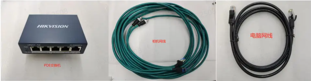
| Accessory name | Quantity | Purpose |
|---|---|---|
| KingFisherCamera | 1 | Collect images |
| Standard gigabit network cable | 1 | Connect to Camera and transmit data |
| Standard power cord | 1 | Connect Camera and Camera power supply |
| Adapted to Calibration Board | 1 | Parameter check, Extrinsic Parameter correction |
4.2 Hardware installation
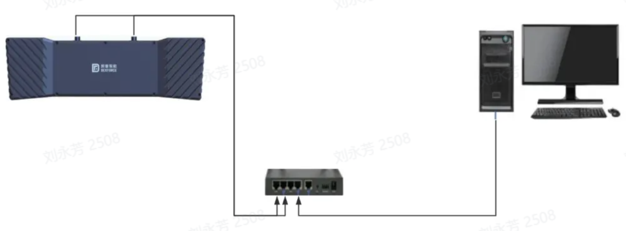
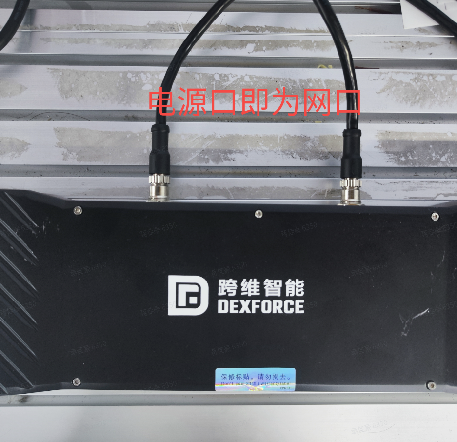
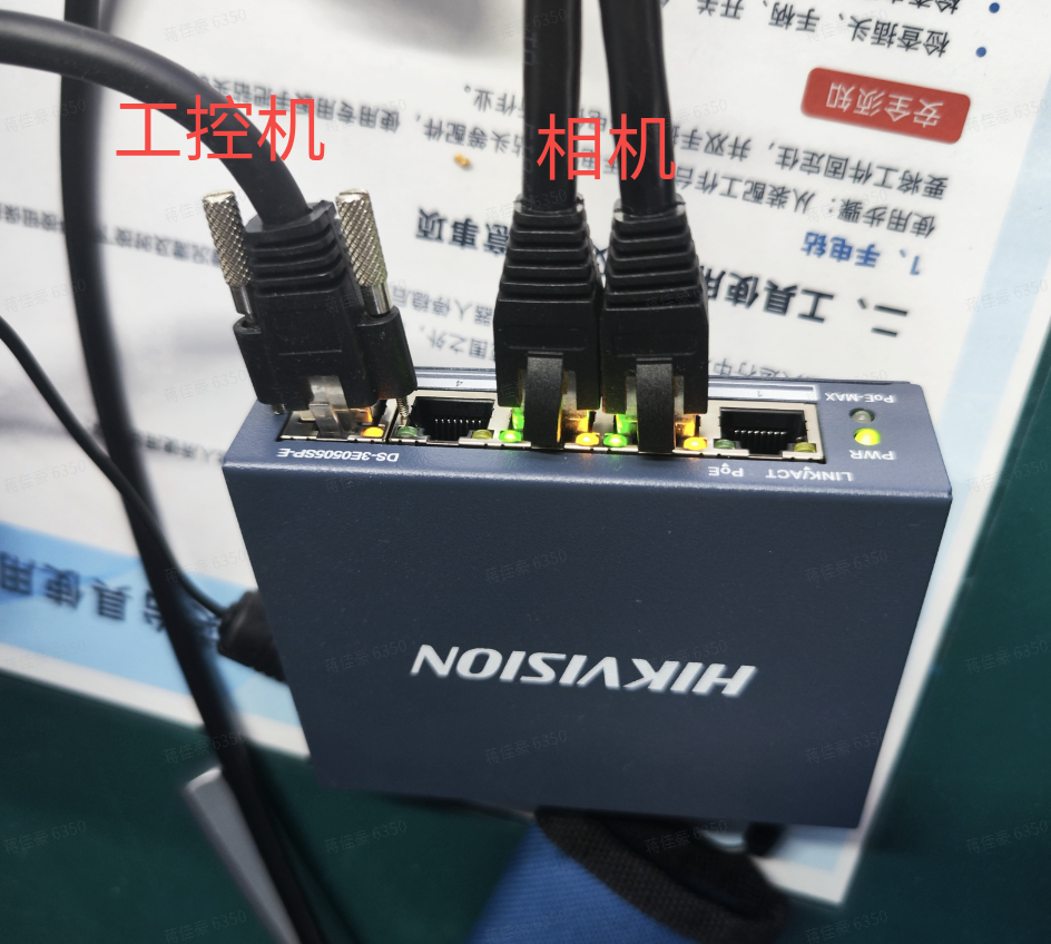
The Camera is connected to the POE switch through a network cable. The POE switch supplies power to the Camera. Connect the computer network cable to the POE switch.
4.3 MVS connection and configuration
MVS installation
MVS software is Hikvision industrial Camera client software. It has functions such as real-time preview of Camera images, modification of Camera device Parameters, screenshots, video storage, and online device upgrades. It can help engineers and developers quickly configure and debug Cameras to ensure the accuracy and stability of image collection.
Dexforce currently uses MVS software to configure and debug KingFisherCamera. The software has been installed on the industrial computer. If you need to install it yourself, please click the following address to download the software https://www.hikrobotics.com/cn/machinevision/service/download/?module=0
MVS Config Camera Normal Connection and Get Internal Extrinsic Parameter Calibration File
[Binocular windows PickWiz deployment (application direction) (internal)] (https://dexforce.feishu.cn/wiki/WscZwoQcuiOYkckGEQRc0MI4nQd?from=from_copylink), refer to the demonstration video or 3.1 ~ 3.2 part of the linked document
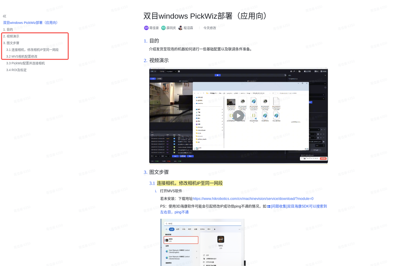
Binocular windows PickWiz deployment (application direction)
Purpose
This article introduces how to perform some basic configurations and prepare joint debugging conditions for machines shipped to the site.
Must-do process: Modify Camera IP to connectable -> pickwiz connects to Camera and configures Point Cloud to be exported -> Redline graph verification (Camera accuracy)
Video demonstration
Picture and text steps
connects to Camera and changes CameraIP to the same network segment
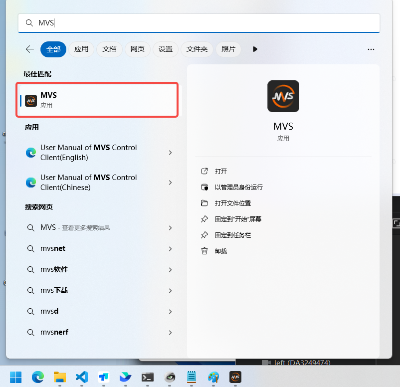
Open the MVS software
If not installed: download address
PS: Using 3D Hikvision software may cause the IP to be modified successfully but the ping fails, such as
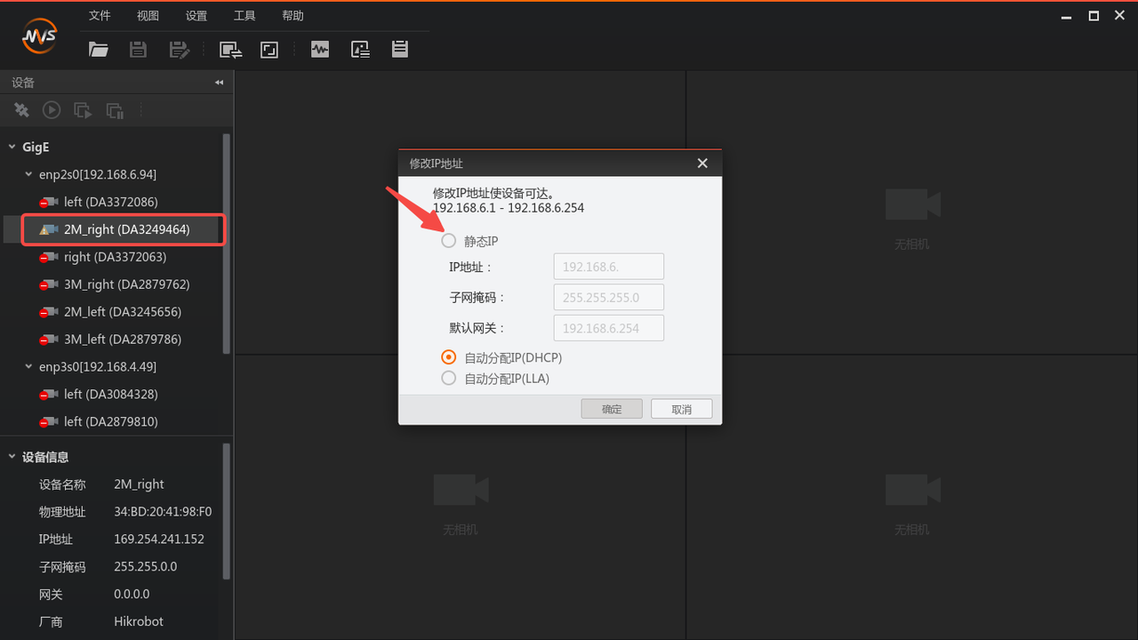
Check the Camera list on the left side of MVS and double-click the Camera you want to connect to. If it cannot be connected, modify the IP. The Camera IP needs to be modified to be in the same network segment as the industrial computer.
If the Camera is directly connected to the industrial computer, it is recommended to set the computer IP to a static IP, and then set the Camera IP to a static IP in the same network segment in MVS.
If you want to set up automatic acquisition, you first need to change it to a static IP (connectable state), and then change the IP again to "Automatically assign IP (DHCP)" after connecting.
The serial number of the Camera needs to be recorded here. If the Camera name is 2M_right (DA3249464), then the serial number of is DA3249464, which will be useful later.
MVSCamera configuration modification
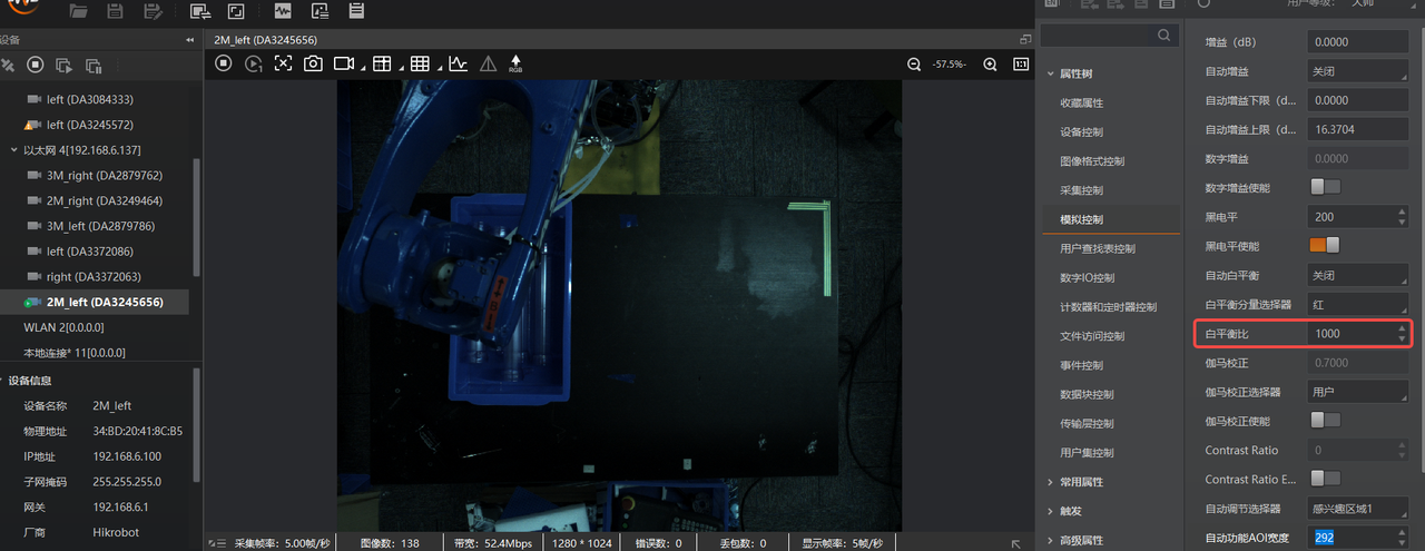
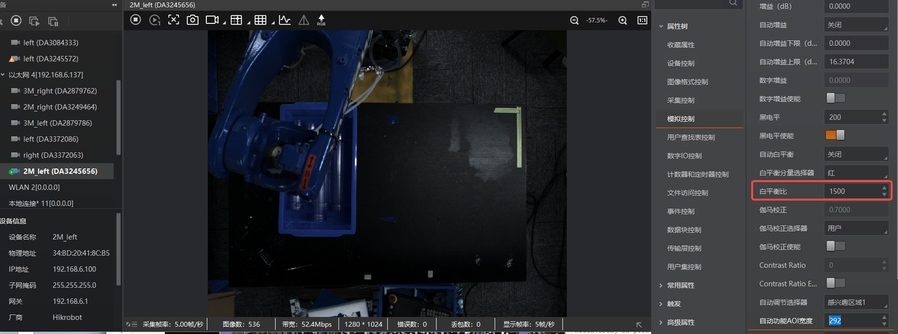
Turn off automatic white balance (color 0, it is recommended that the balance ratio of the two cameras be filled in consistent)
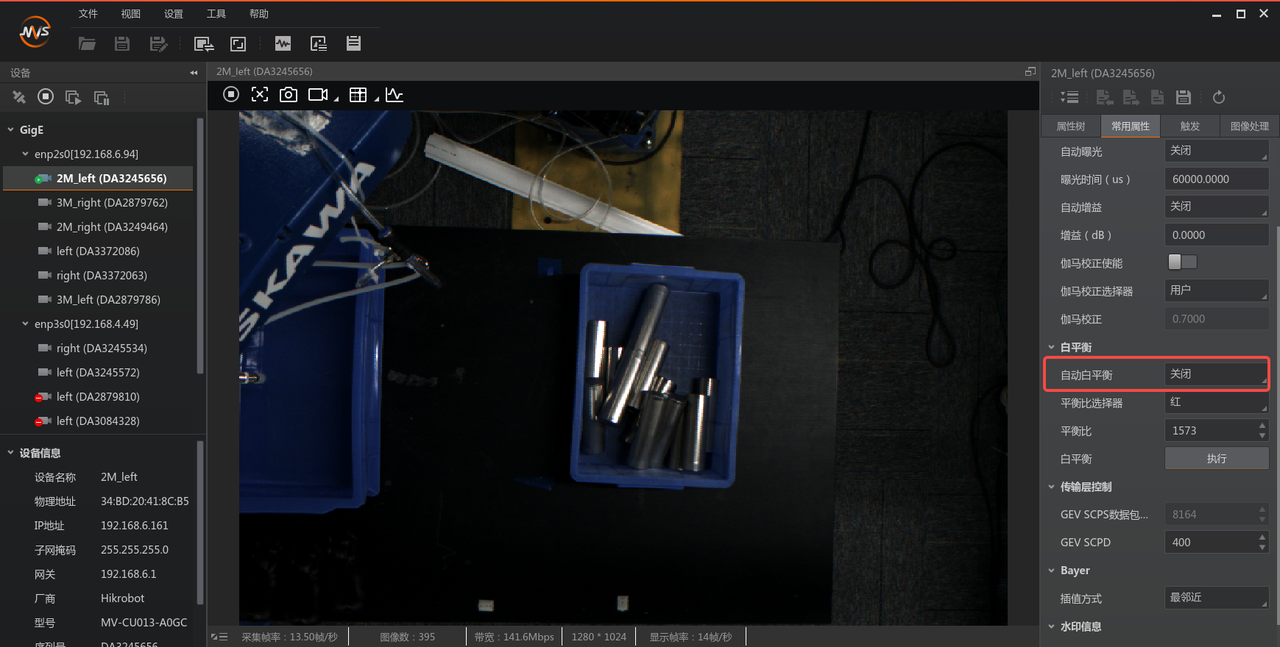
If the Camera white balance values are different, the picture tone will be inconsistent, as shown in the two pictures below.
Recommended for normal display effect:
Fill in the "White Balance" value as 1500. PS: The high-resolution color tone is cooler, you can fill in 1800, which is consistent with the perception of the human eye.
Select "Red" for the "White Balance Component Selector".
Automatic exposure AOI settings
Click the box pointed by the arrow, click "Edit" to draw the AOI
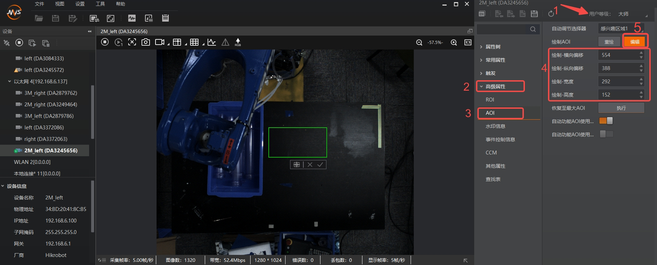
"Auto-exposure AOI" means that it only cares about the exposure within the AOI, so that the texture in the frame is clear, but the automatic exposure value is global, so there may be situations where the "part of concern" is clear and the rest is overexposed.
A green box appears
Place the mouse in the center of the green box and click to drag the AOI area
Place the mouse on the green frame line to stretch the AOI area
After completing drawing the AOI, record the AOI box data and turn on the "Automatic Function AOI Usage Intensity" as shown below
The AOI box data includes: horizontal offset, vertical offset, width and height , which need to be filled in manually into the Pickwiz software CameraParameter
In the image preview box, right-click and click "Finish" to complete the AOI configuration.
Close MVS and disconnect from Camera
4.4 PickWiz configures and connects Camera
PickWiz software configuration
Import model
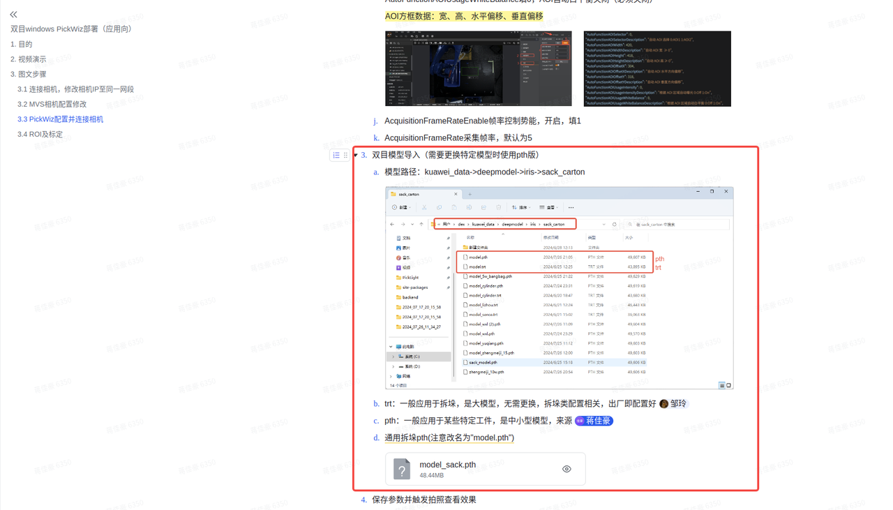
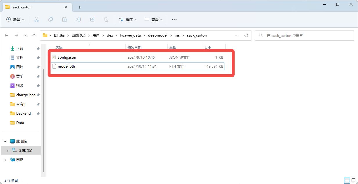
After obtaining the binocular model pth file, put the pth file in the "kuaweidata/deepmodel/iris/sack_carton/" directory and rename it to model.pth. For the access method, see [Binocular Windows PickWiz Deployment (Application Direction) (Internal)] (https://dexforce.feishu.cn/wiki/WscZwoQcuiOYkckGEQRc0MI4nQd?from=from_copylink)3.3 Chapter
Open the software for connection and Parameter configuration
config.json configuration: The path is as shown below. If it does not exist, create a new file with the same name and focus on modifying max_dispParameter.
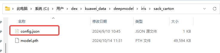
{//内容解析 "matcher_type": "pth",//模型类型,“pth”或“trt” "max_disp": 256,//视差值, //视差计算公式disp = fx * baseline / distance "igev_refine_iters": 32,//迭代次数 "scale_x": 1.0,//2D图像x方向的放缩比 "scale_y": 1.0,//2D图像y方向的放缩比 "rectify_enlarge": false,//是否恢复全局视野 "roi_delta_x": 0//x方向的roi2d窗口偏移 }
max_disp means the maximum disparity, that is, the maximum and minimum working distances are calculated once and the maximum value is obtained.
calculation formula: disp = baseline length * CameraIntrinsic Parameterfx / distance from the object
connect
Binocular configuration is checked, if not, press the "+" sign to create a new one.
Different CameraParameters can be set for the left and right eyes.
Internal Extrinsic Parameter configuration import reference [Binocular windows PickWiz deployment (application direction)] (https://dexforce.feishu.cn/wiki/WscZwoQcuiOYkckGEQRc0MI4nQd?from=from_copylink)3.3 chapter
For high resolution, first set the scaling ratio to 0.33 (3036*4024)
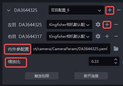
Parameter introduction and configuration ( is long, it is recommended to browse all )
4.5 Download the Extrinsic Parameter calibration file
The internal Extrinsic Parameter calibration file is the factory configuration file of DexforceCamera, which is used to illustrate the relative relationship between the left and right cameras.
Find the corresponding Extrinsic Parameter calibration file [KINGFISHER-Camera calibration file] (https://dexforce.feishu.cn/wiki/Qqcnw7aHWik2JNk2ZWbcCV0dn9k) according to the Camera model and serial number (left and right SN), as shown in the figure below, download the latest version of the calibration file.
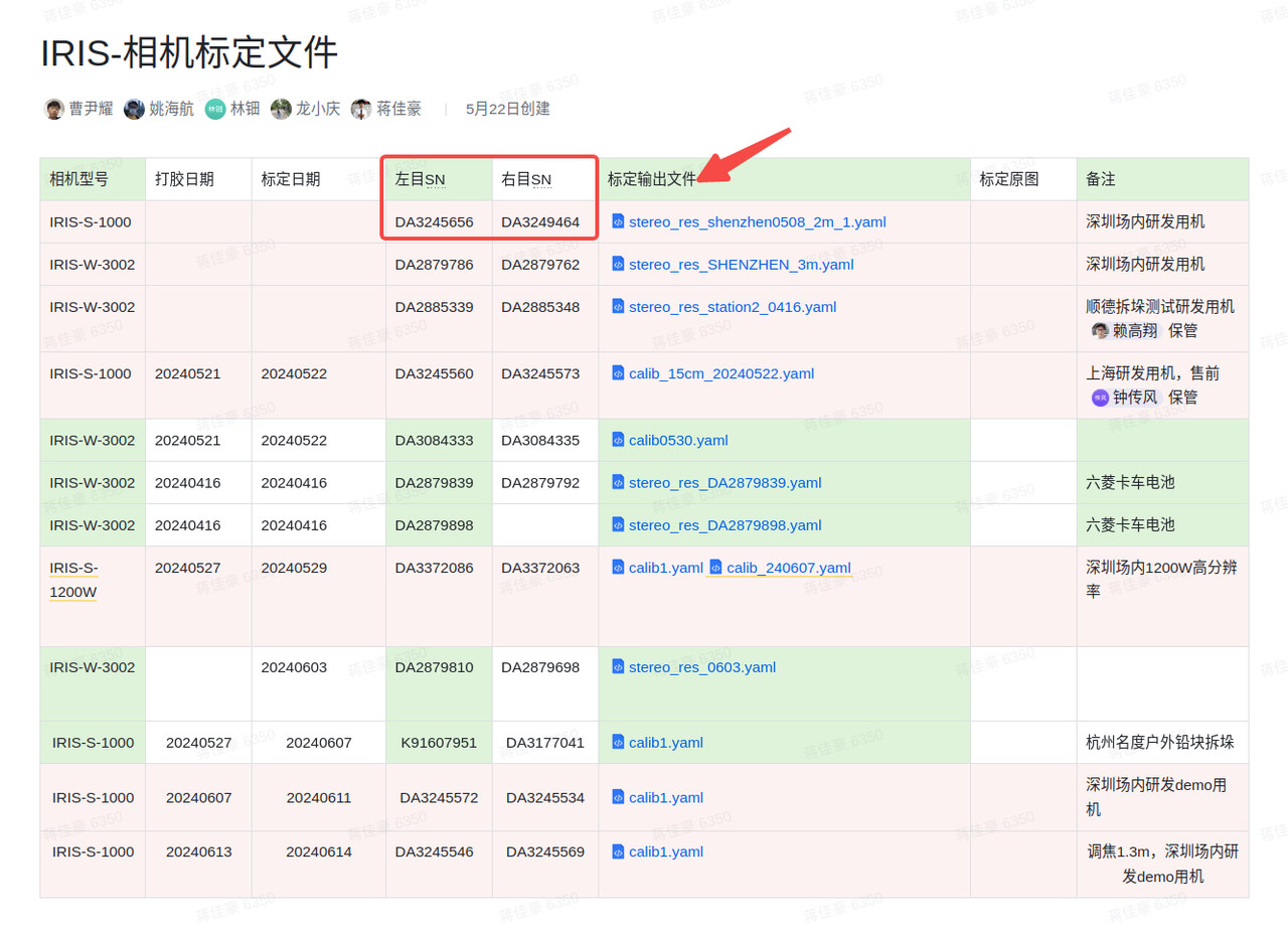
If you cannot find the corresponding calibration file, you can find confirmation
Get the Extrinsic Parameter calibration file in Camera
Query the Camera serial number recorded in step a under this link [KINGFISHER-Camera calibration file] (https://dexforce.feishu.cn/wiki/Qqcnw7aHWik2JNk2ZWbcCV0dn9k)
Compare the left and right SN numbers (serial numbers), to download the corresponding calibration file . PS: If you cannot find the corresponding calibration file, you can find it to confirm
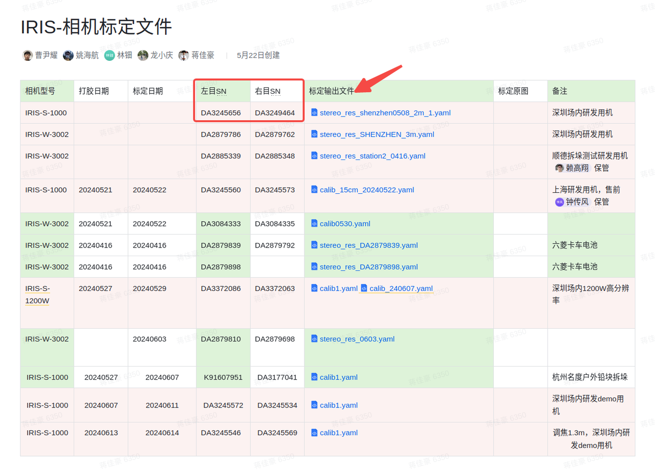
Binocular model import (using pth version)
- Model path: kuawei_data->deepmodel->iris->sack_carton, does not have this path, you need to manually create
~~trt: Generally used for destacking, it is a large model and does not need to be replaced. It is related to the destacking configuration and is configured at the factory ~~
pth: source
Universal destacking pth (, please rename it to "model.pth" )
Configure the stereo model Parameter config.json
After version 1. Content and modify it appropriately. Note: max_disp means the maximum disparity, that is, the maximum and minimum working distances are calculated once and the maximum value is obtained. Then see if the calculated disparity value is less than 256, 384 or 512, fill in the "max_disp" Parameter.
calculation formula: disp = baseline length * CameraIntrinsic Parameterfx / distance from the object
Note: Baseline length, KingFisher-S-1000 is 0.15, KingFisher-W-3002 is 0.40.
Low-resolution fx is generally about 1275, and high-resolution fx is about 3000*scale based on the scaling ratio.
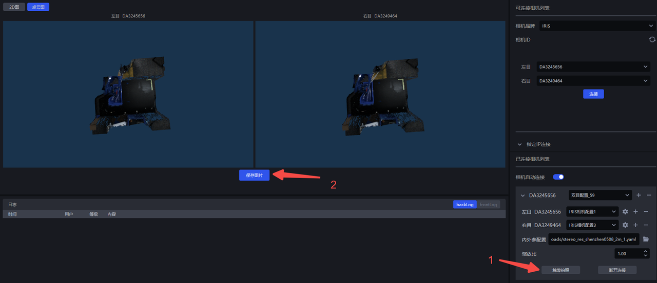
Save the Parameter and trigger the photo to view the effect
Note: It is best to keep the parameters of the left and right eyes consistent except for AOI. The AOI can also be consistent when the range requirements are not strict. Check whether the picture taking effect and style of the left and right eyes are consistent. If a color cast occurs, it may be that the automatic white balance is not turned off, or the camera has recorded the value before turning off the automatic white balance. In this case, you need to enter the MVS to refill the white balance ratio value.
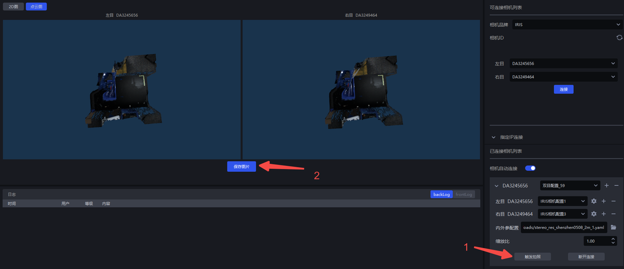
When binocular data verification is required in the field, you can directly take pictures and save the pictures, and then send the "save picture" data.
Check whether the Camera is normal (whether Extrinsic Parameter correction is needed)
This step is necessary, otherwise the image collection may fail.
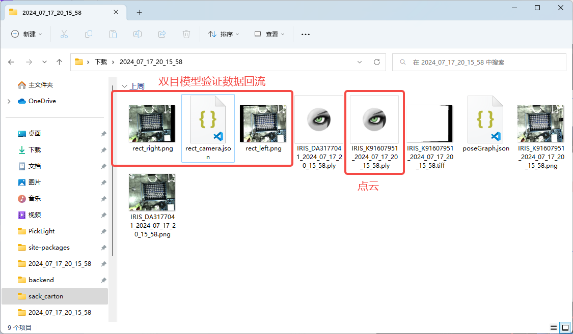
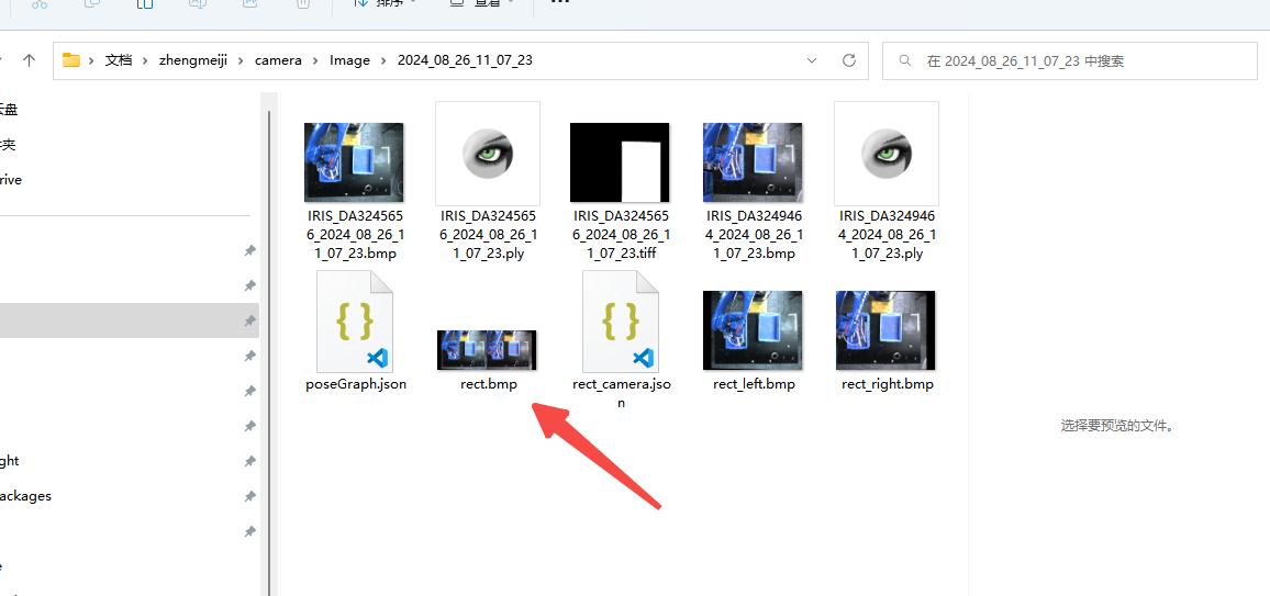
After saving the picture in the Camera interface, open the saved folder
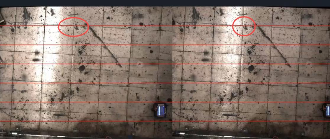
Find rect.bmp, check whether the red line passes through the same point in the left and right images. The normal situation is as follows: you can see that the red line passes through the same point in the actual scene, proving that the Extrinsic Parameter of the Camera is correct; otherwise, the Extrinsic Parameter needs to be corrected (for specific steps, please refer to [ROI and Eye-hand calibration] (https://dexforce.feishu.cn/wiki/WscZwoQcuiOYkckGEQRc0MI4nQd#share-PnUgdNIrzoIiL5xRkdLcbjjRnrd)).
4.6 ROI
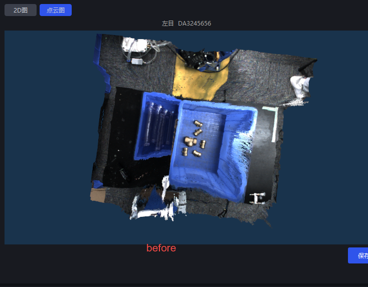
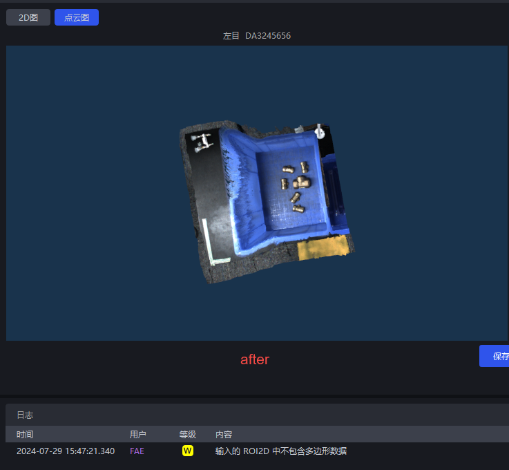
ROI settings
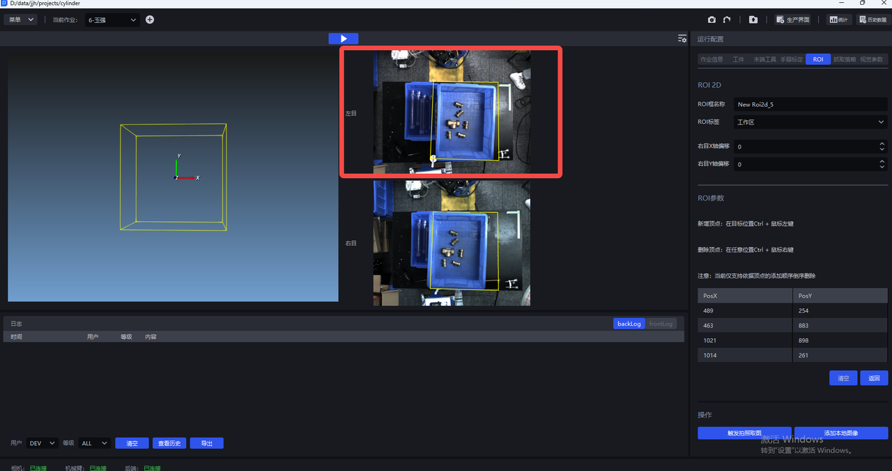
Recognition-oriented ROI2D focuses on the left eye (work area)
Point Cloud crop ROI2D (observation area)
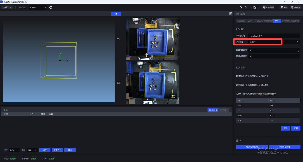
After the setting is completed, only the Point Cloud within the ROI range will be generated, which can improve the cycle time and remove the interference of other Point Clouds. PS: There may also be situations where the quality of the Point Cloud is not up to standard after setting the ROI. This must be considered based on actual conditions.
4.7 Eye-hand calibration
For the Eye-hand calibration operation procedure, please refer to the relevant instructions of Eye-hand calibration
After the Camera connection is completed, Eye-hand calibration needs to be performed, otherwise it will affect the image capture effect.
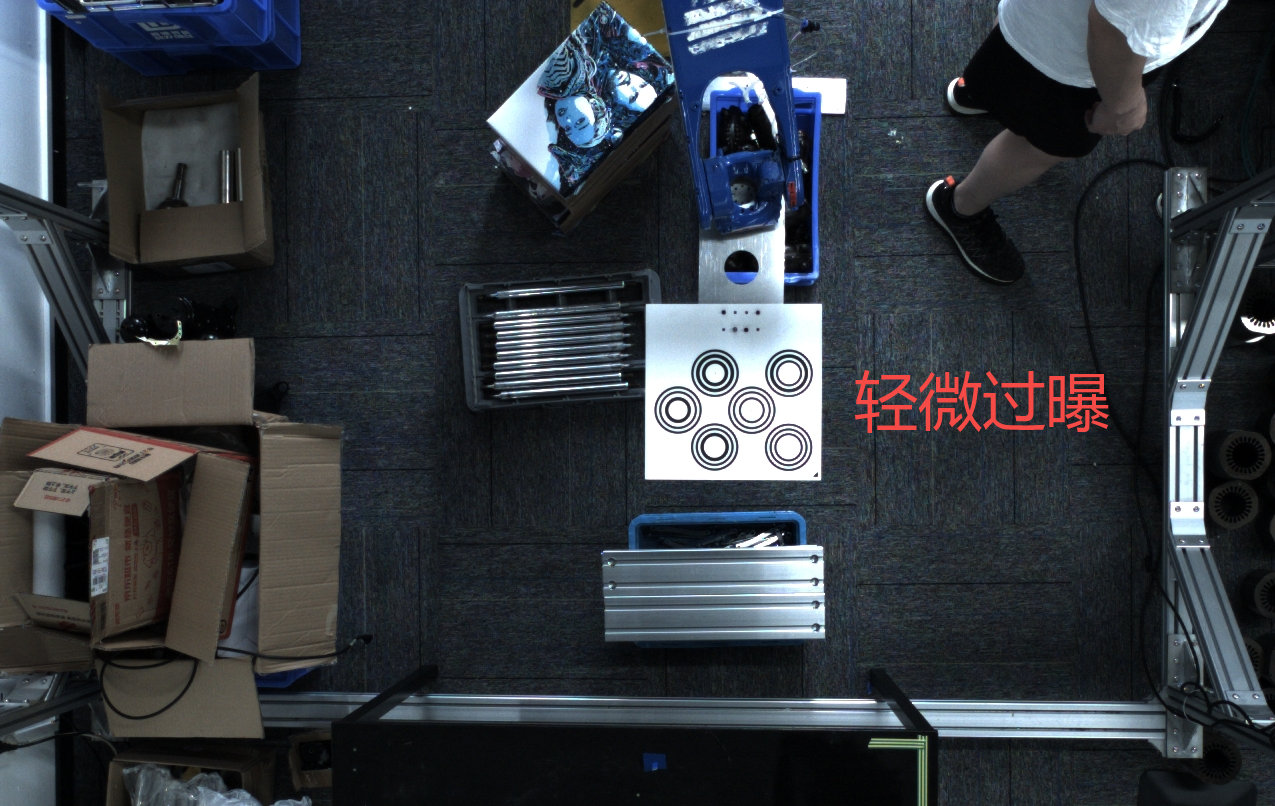
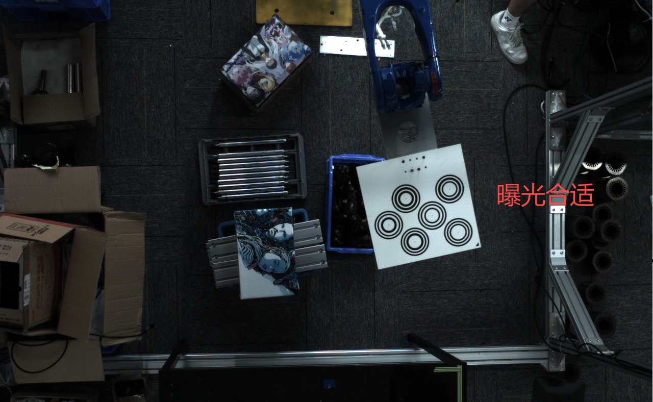
Adjust the AOI properties of the MVS software to fixed exposure
Camera collects images according to the Eye-hand calibration process.
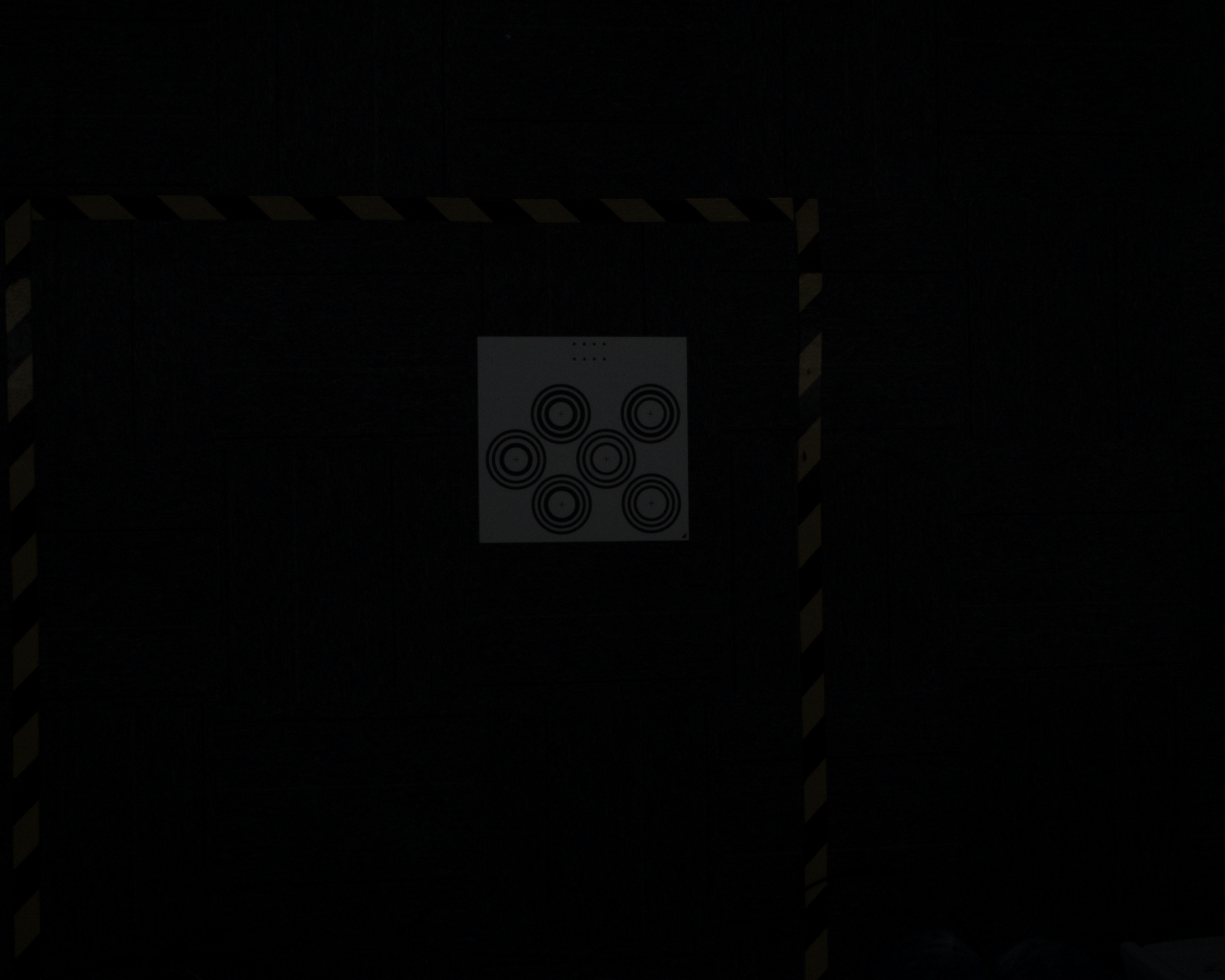
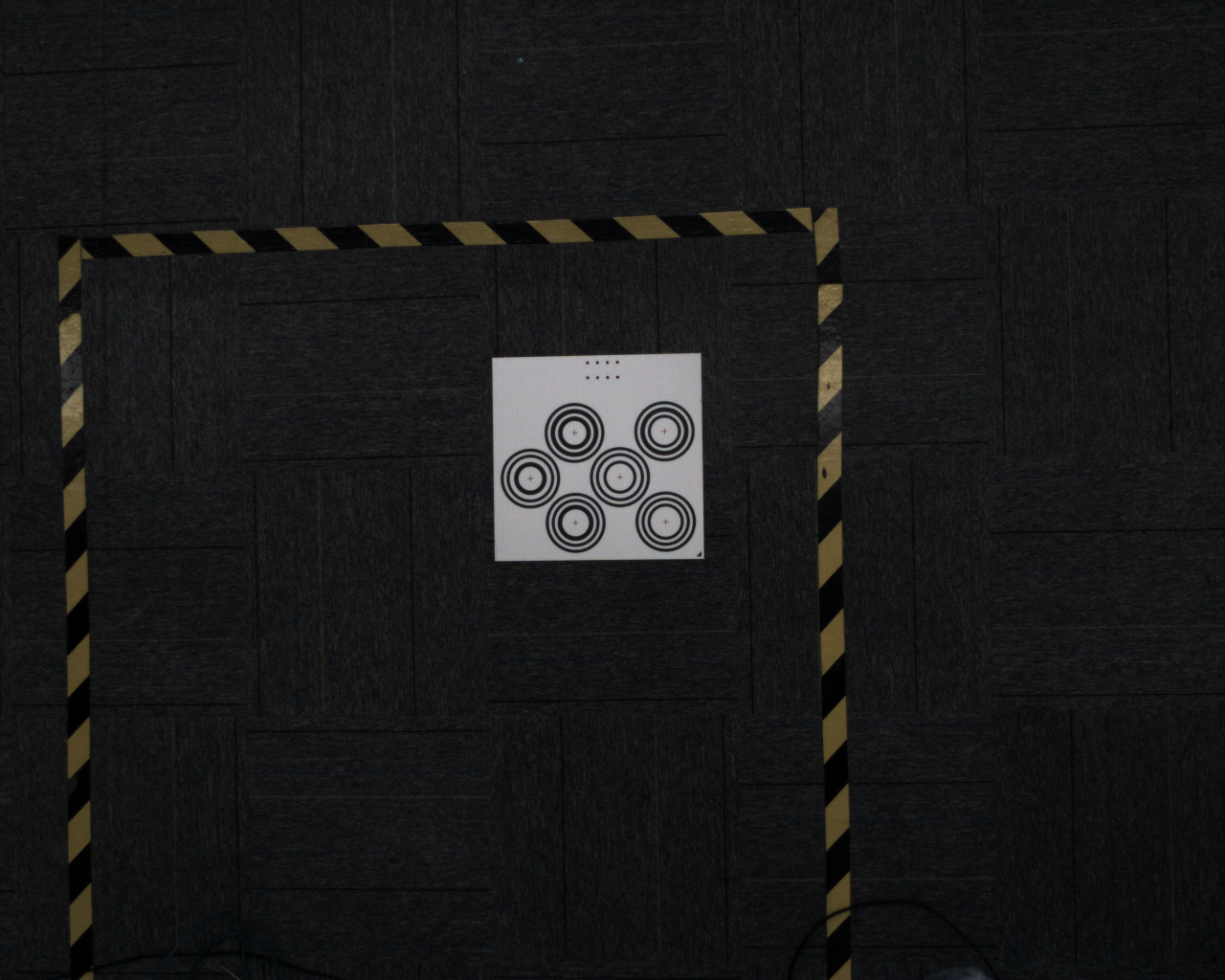
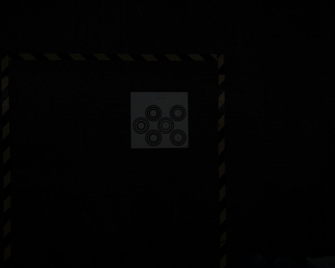
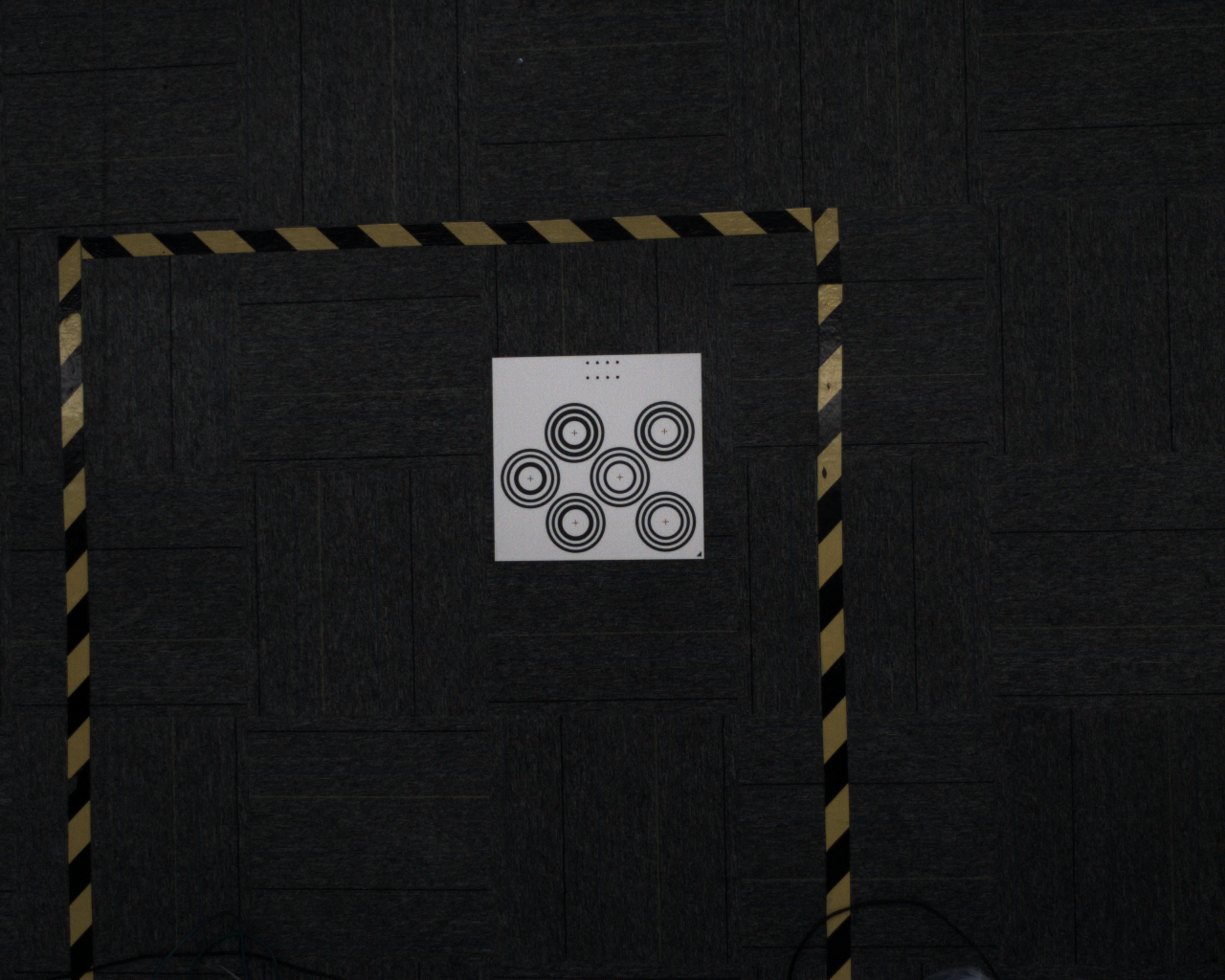
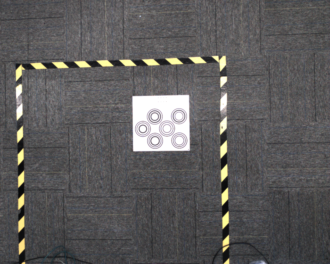
Adjust the brightness of the picture so that the Calibration Board is not overexposed, as shown in the picture below (right)
Extrinsic Parameter correction
If the calibration error is small, but there is a large error in the actual stamped point, point cloud deformation, etc., after confirming that human operation factors have been eliminated, check the red line diagram saved by taking the camera photo to confirm whether it is caused by changes in the camera structure during transportation, and Intrinsic Parameter correction is required.
5. Camera configuration
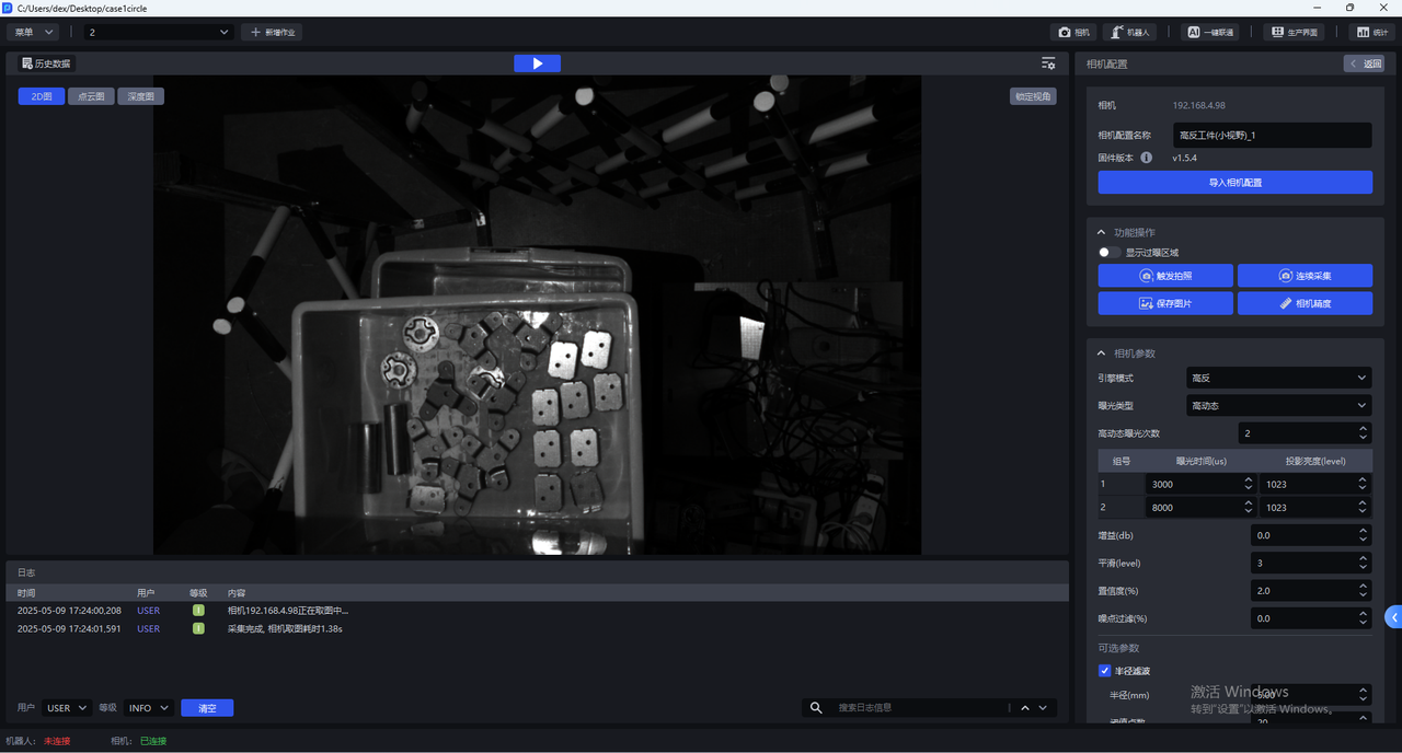
- Each Camera has multiple default configurations, and all default configurations cannot be changed. Select the corresponding default configuration, click "Trigger photo", use the imaging parameter to capture 2D images, Point Cloud images, and Depth images. You can check the imaging quality in the visualization window on the left.
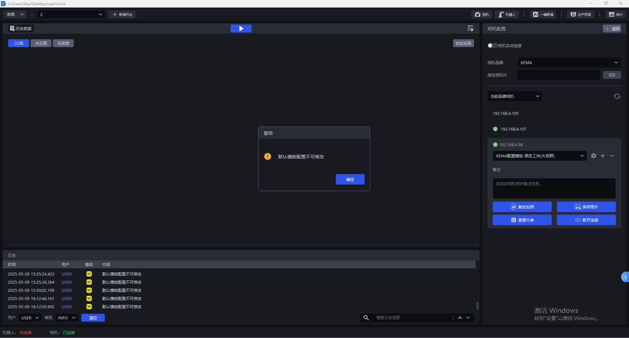
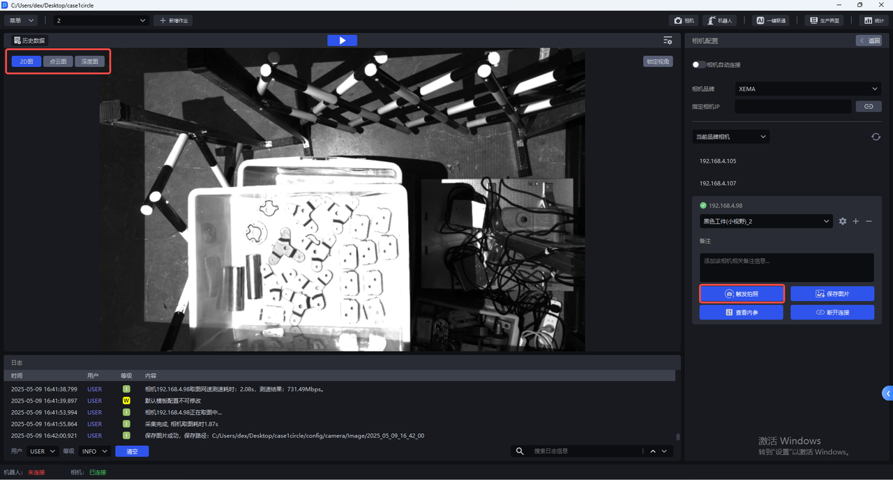
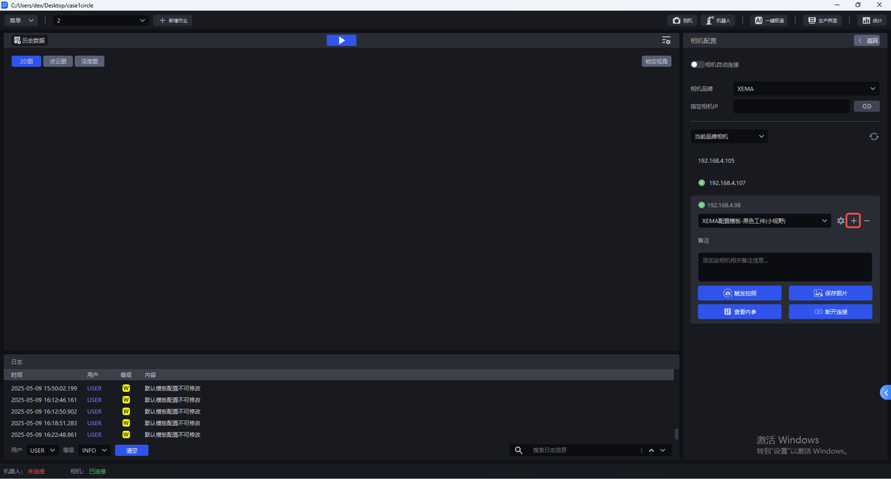
- The default camera configuration cannot be changed. If all 2D images taken with the default configuration cannot achieve normal exposure, you can click
+to copy the current Camera default configuration, add an identical Camera configuration, and directly enter the Camera configuration interface to modify Parameter.
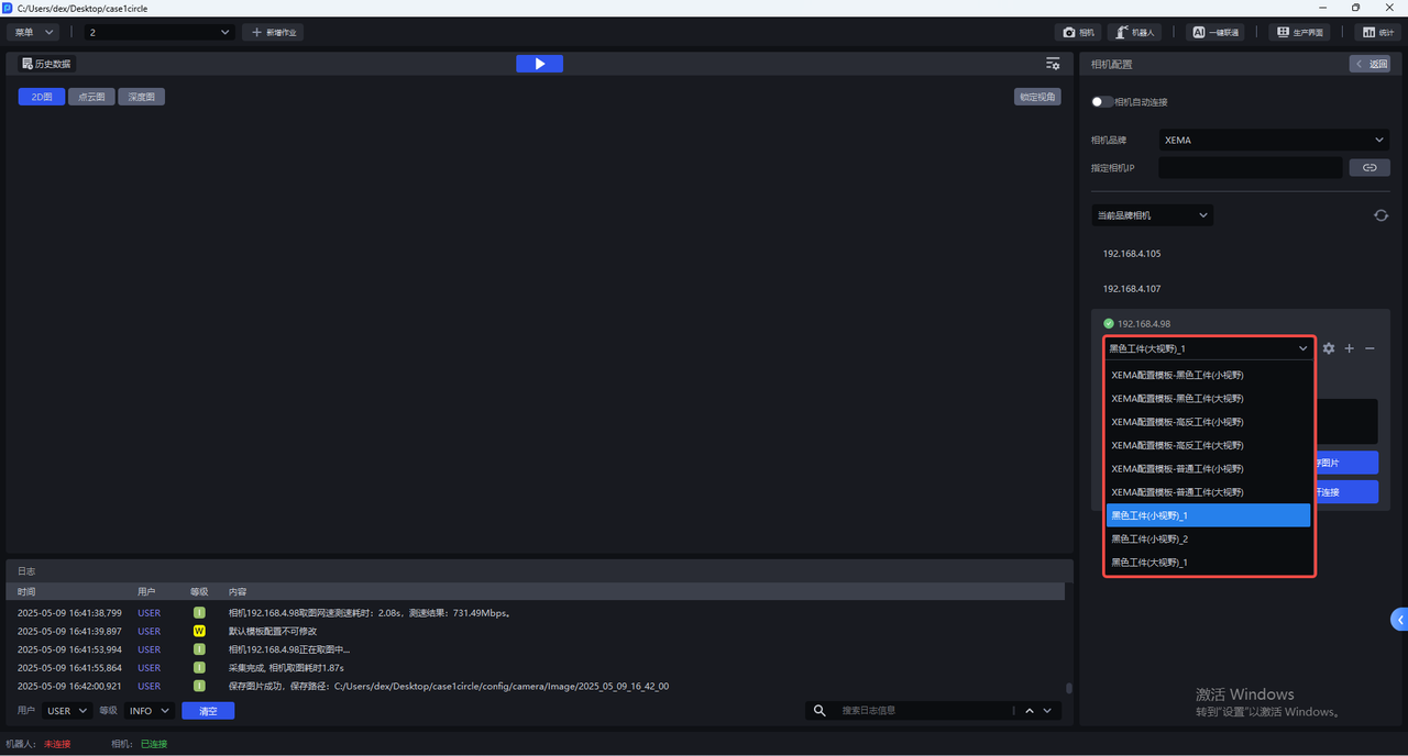
After copying the current Camera default configuration, you can switch to the new Camera configuration, click the Settings button , and enter the Camera configuration interface to modify Parameter.
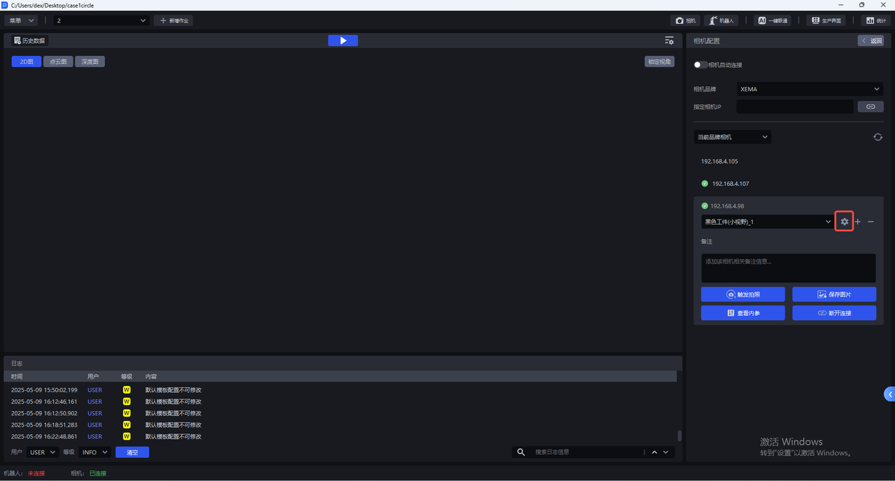
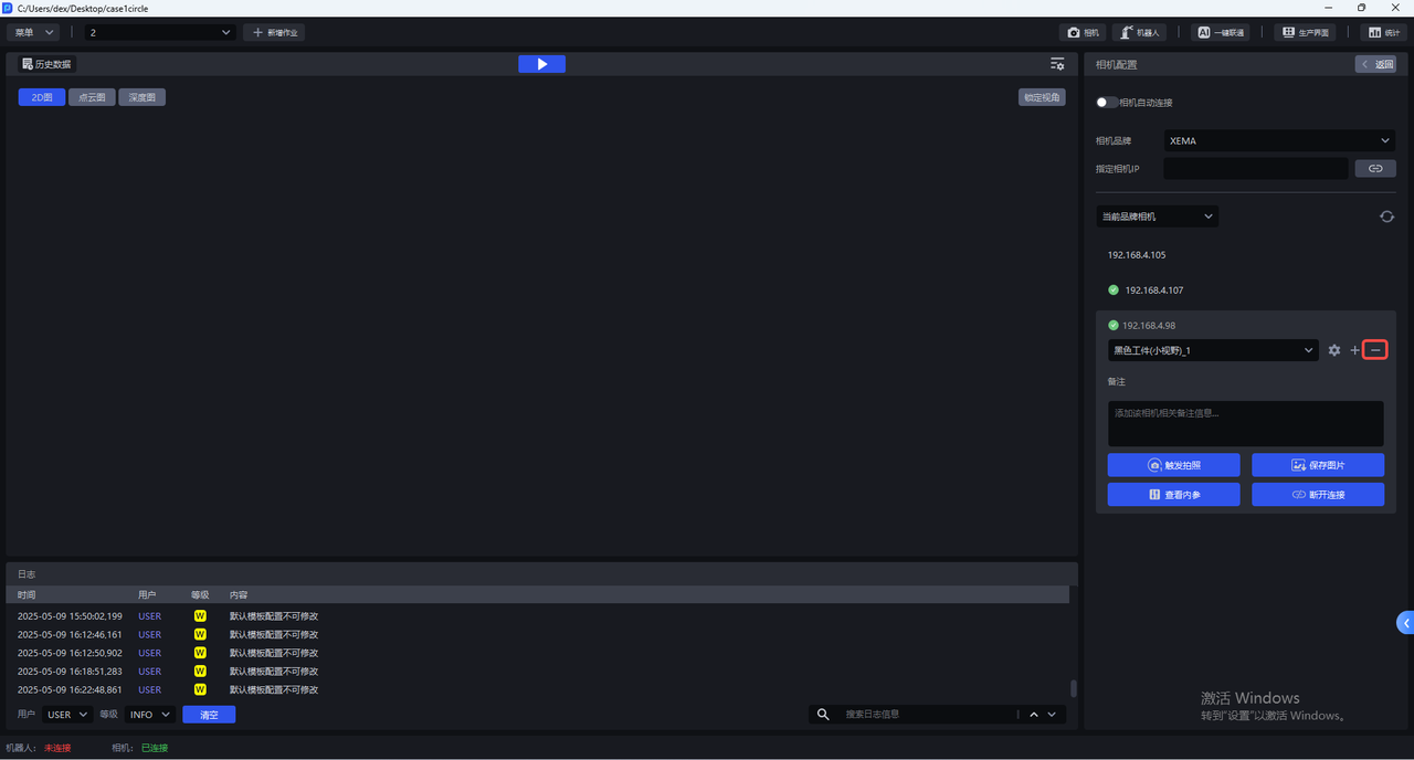
Click — to delete the newly added Camera configuration.
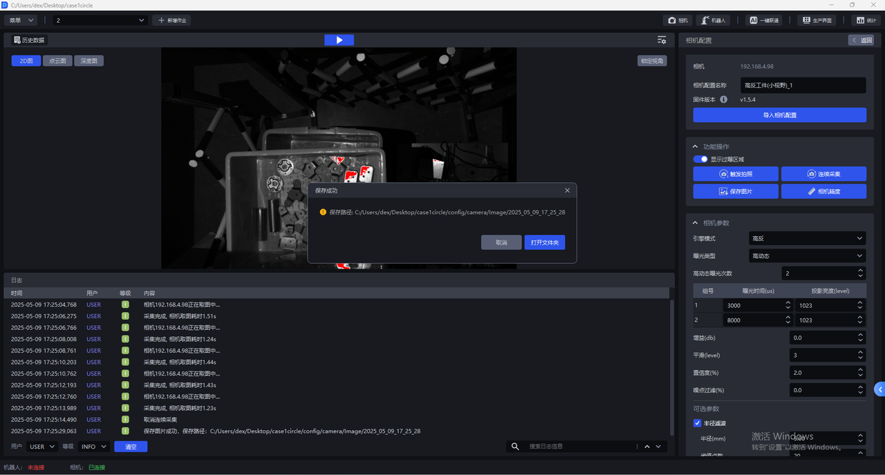
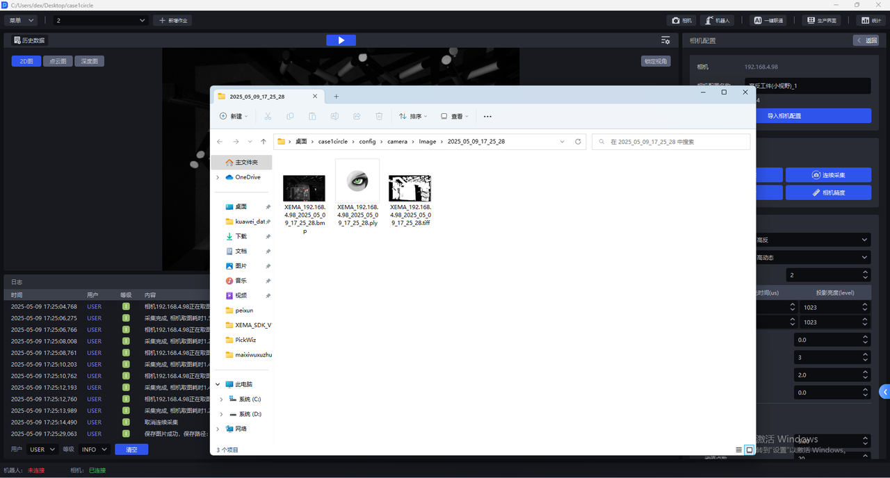
- Click
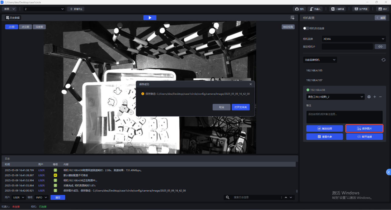
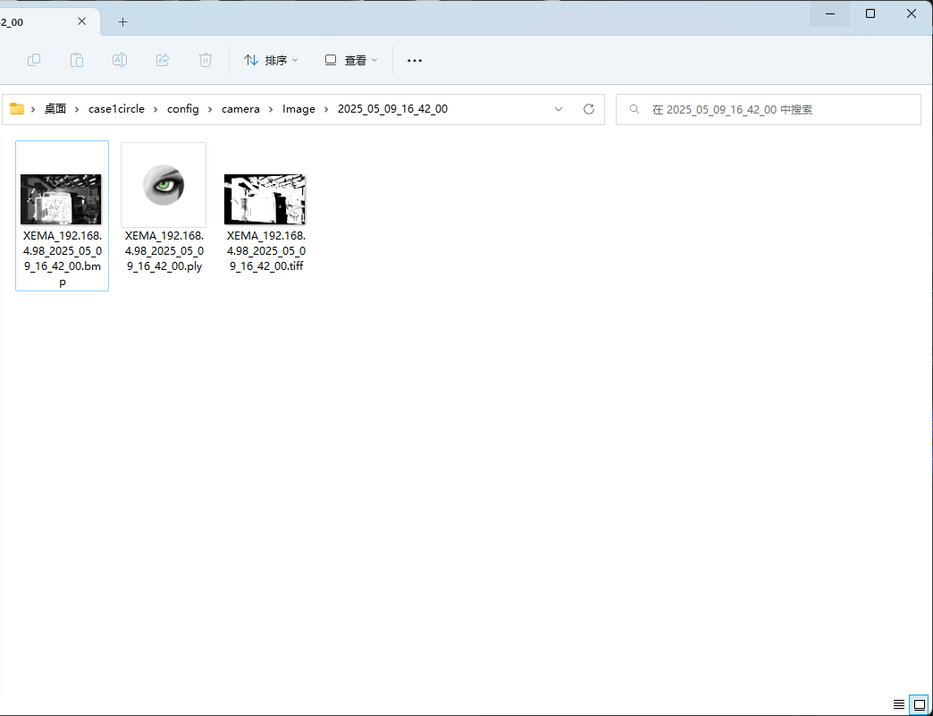
Save Imageto save the 2D image, Point Cloud image, and Depth image taken using the current configuration to the local machine, as shown in the figure below. The saving path is the project folder/config/camera/image/shooting time. The suffix is bmp for the 2D image, the suffix for the ply is for the Point Cloud image, and the suffix for the tiff is for the Depth image.
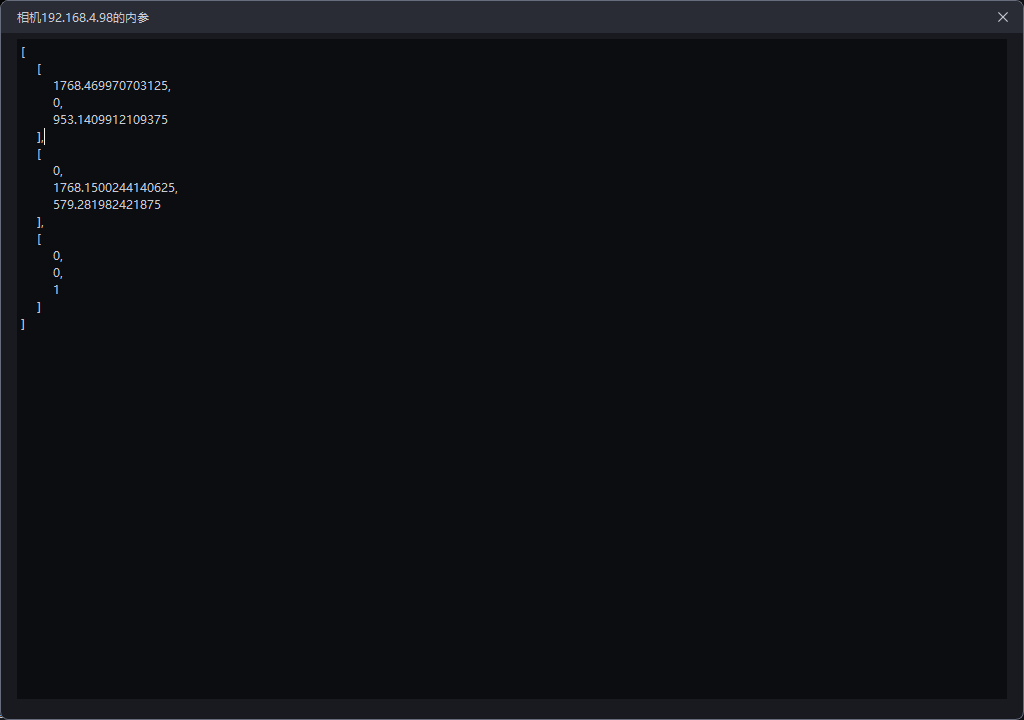
- Click
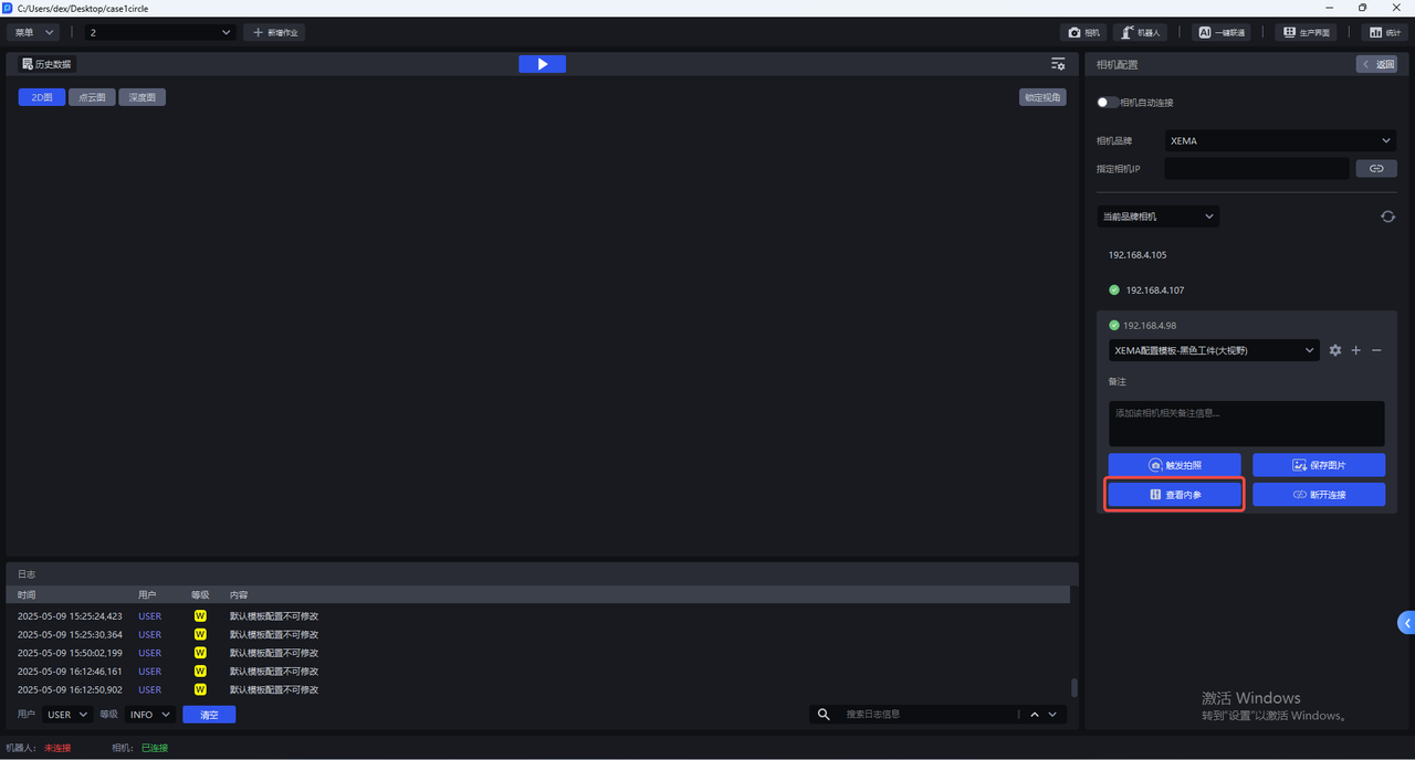
View Intrinsic Parameterto view CameraIntrinsic Parameter, including lens focal length, principal point coordinates, distortion coefficient, etc.
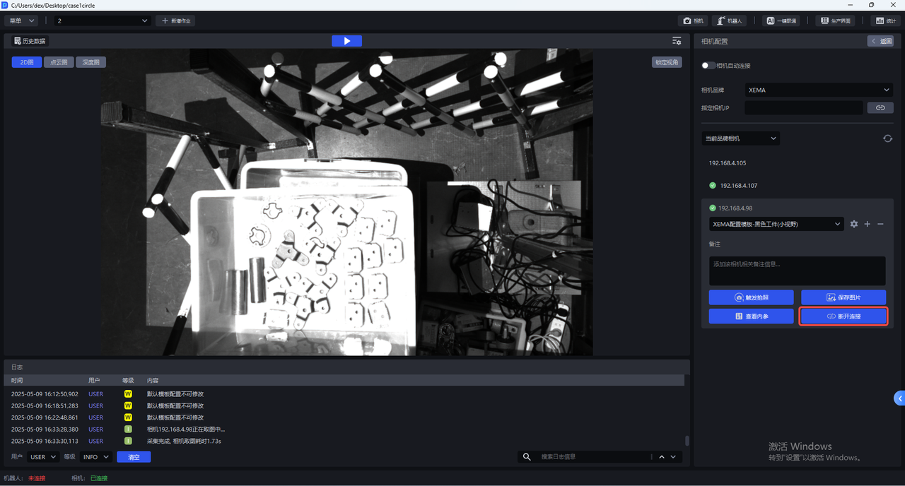
- Click
Disconnectto disconnect the Camera and re-select the Camera connection.
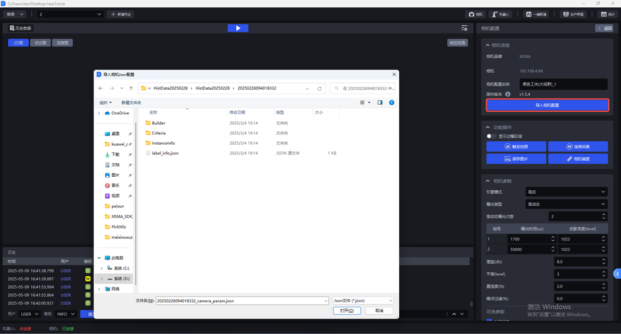
5.1 Import Camera configuration
Enter the Camera configuration interface and click Import Camera Configuration to import the existing Camera configuration into the Camera.
5.2 function operation
The Camera configuration interface has the following functions:
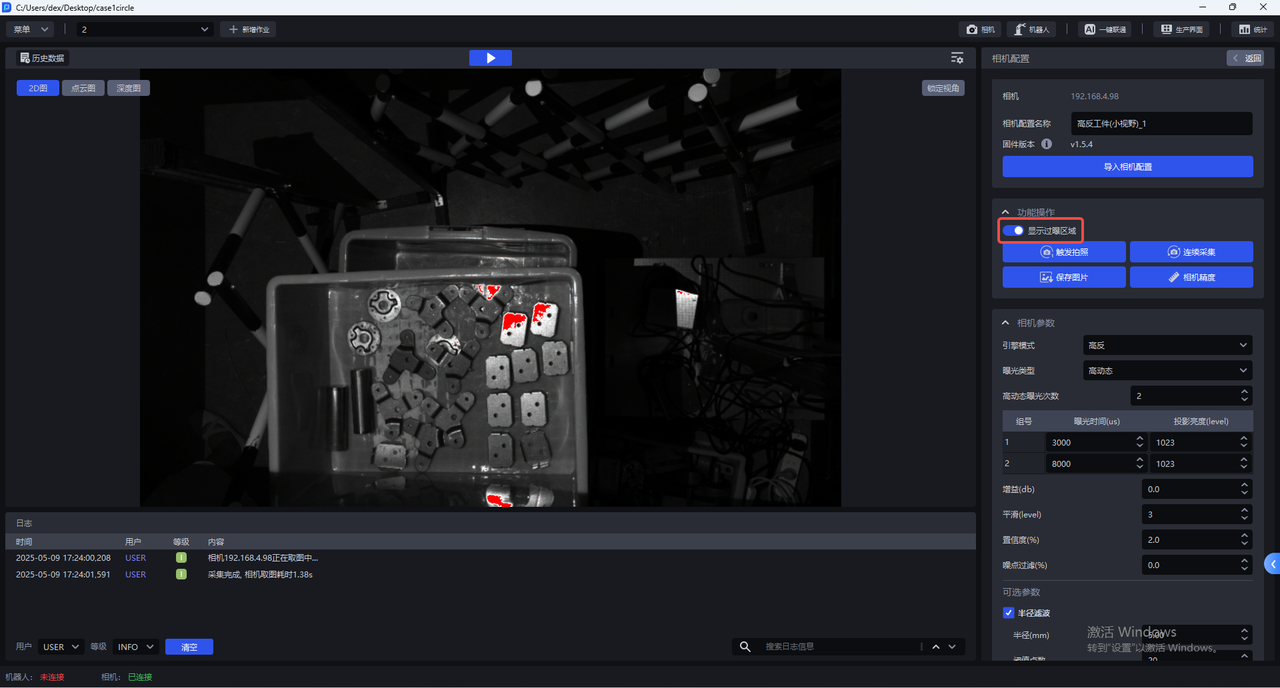
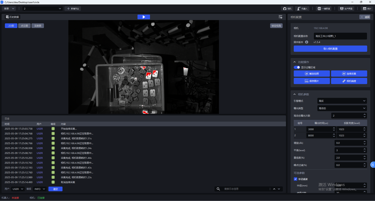
- Show overexposed areas
After turning on Show overexposure area, the visualization window will display the overexposure area of the current image, as shown in the figure below.
- Trigger photo
Click Trigger Photography to shoot 2D images, Point Cloud images, and Depth images using the current Camera configuration. You can check the imaging quality of the current Camera configuration in the visualization window.
- Continuous collection
Click Continuous Acquisition and the Camera will take pictures continuously. Click Cancel Acquisition to stop taking pictures.
- save image
Click Save Image to save the captured 2D image, Point Cloud image, and Depth image
- Camera accuracy
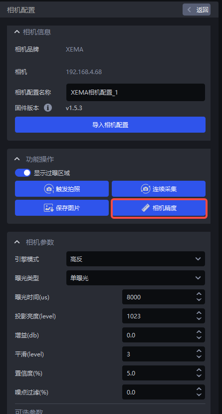
Click Camera Accuracy to view and verify Camera accuracy
5.3 Camera accuracy
5.3.1 View Camera accuracy
- Place the Calibration Board within the Camera's field of view, click
Camera Accuracyin the Camera configuration interface, and the Camera Accuracy interface will appear, as shown in the figure below
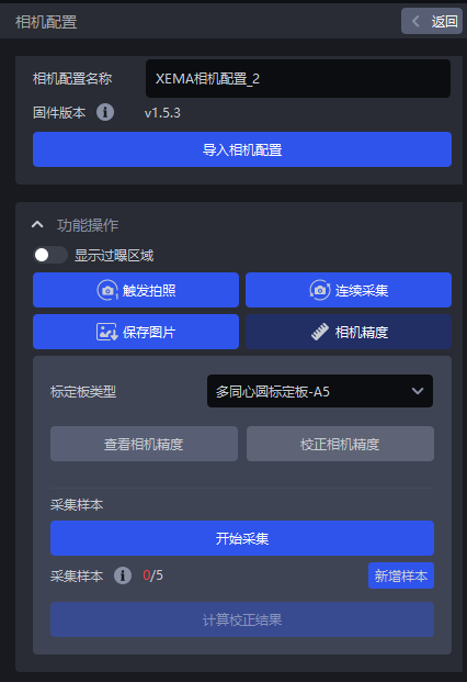
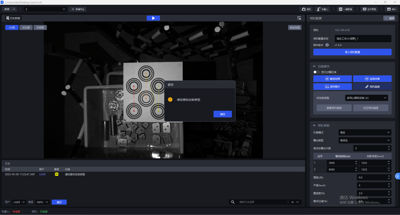
- Select the corresponding Calibration Board. If the selected Calibration Board does not match the actual one, a pop-up warning "Please check the Calibration Board type" will pop up, as shown in the figure below. If the Calibration Board type is A3, a pop-up warning will pop up.
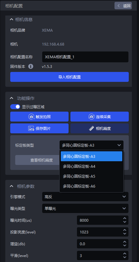
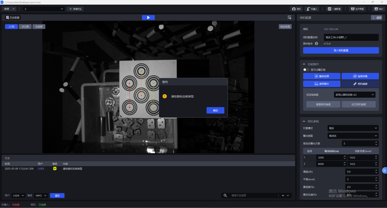
- After selecting the correct Calibration Board type, click
View Camera Accuracy, and PickWiz will automatically calculate the Camera accuracy of the current Camera. If the Camera accuracy meets the requirements, directly adjust the Camera imaging Parameter; if the Camera accuracy is too large, a prompt box will pop up saying "The error is too large, it is recommended to correct the Camera accuracy."
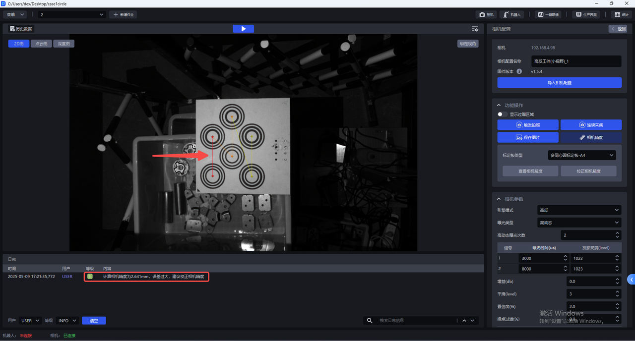
Camera accuracy of each series of cameras <Xmm indicates that the accuracy meets the requirements
XEMA-D:0.2mm
XEMA-S:0.2mm
XEMA-L:0.5mm
5.3.2 Calibrate Camera accuracy
During the actual use of the Camera and after the Extrinsic Parameter is corrected, it is necessary to verify whether the accuracy of the current Camera meets the requirements.
Check the Camera accuracy. If the Camera accuracy error is abnormal, the Camera accuracy should be corrected;
The current Point Cloud captured by the Camera fluctuates greatly, and the Camera accuracy should be corrected.
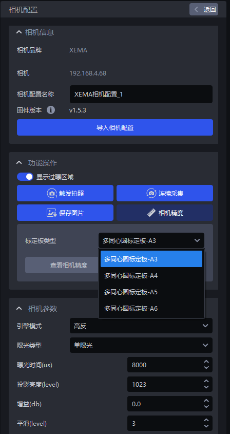
Before correcting the camera accuracy, you should turn on `Show overexposure area' to check the exposure level of the Camera imaging. If there is an overexposed area, adjust the exposure time of the single exposure to ensure that the Camera imaging exposure is normal.
After the correction is completed, the Camera imaging Parameter should be switched back to its original configuration.
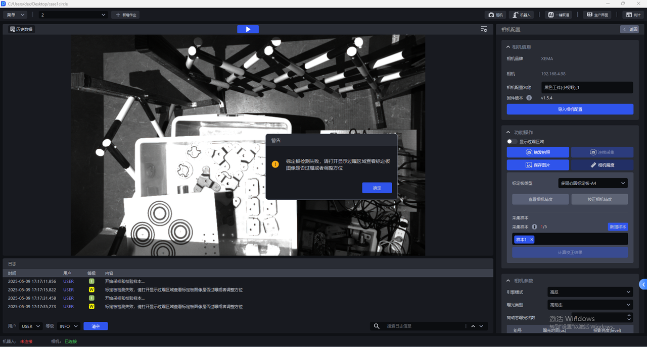
- Click
Camera Precisionin the Camera configuration interface
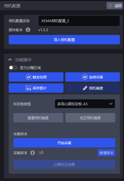
- Select the corresponding Calibration Board. If the selected Calibration Board does not match the actual one, a pop-up warning "Please check the Calibration Board type" will pop up, as shown in the figure below. If the Calibration Board type is A3, a pop-up warning will pop up.
- After selecting the correct Calibration Board type, click
Calibrate Camera Accuracy
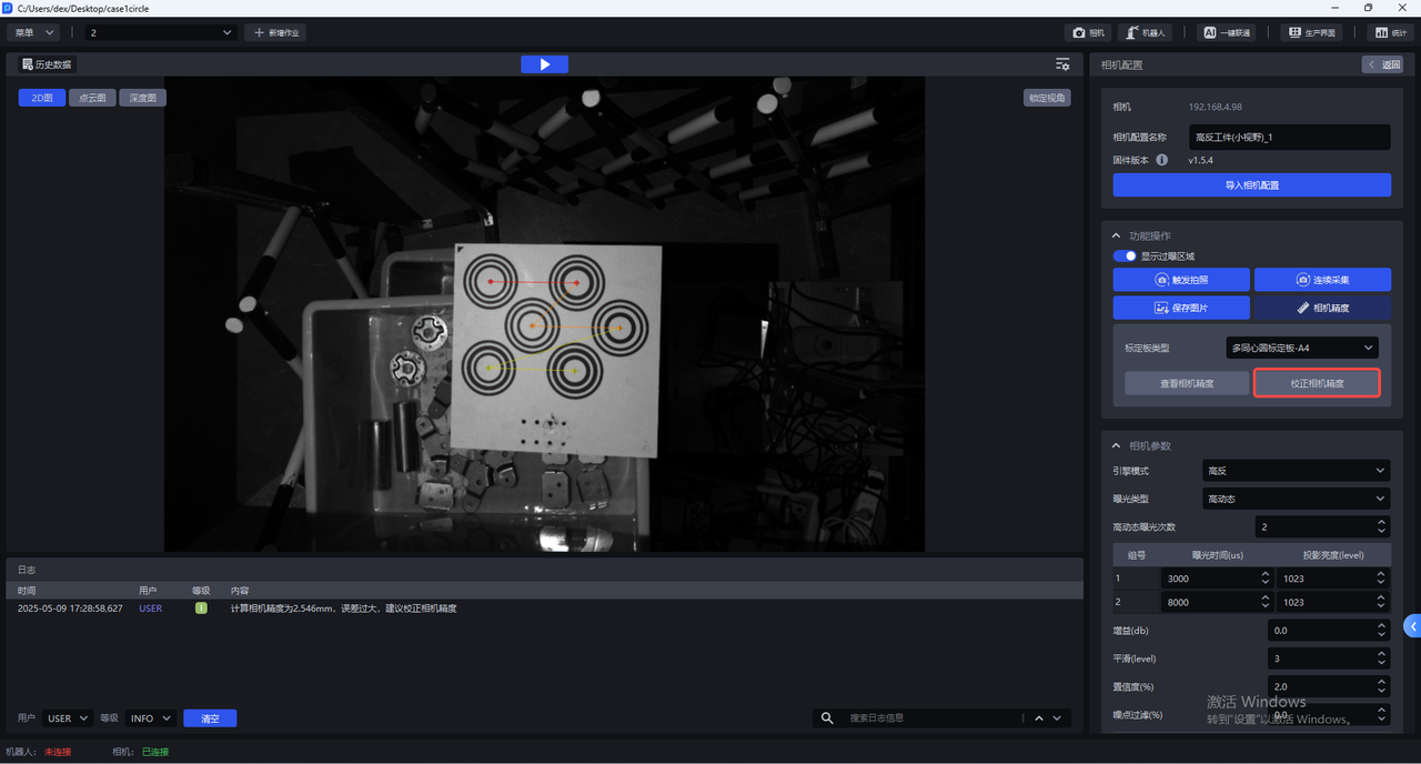
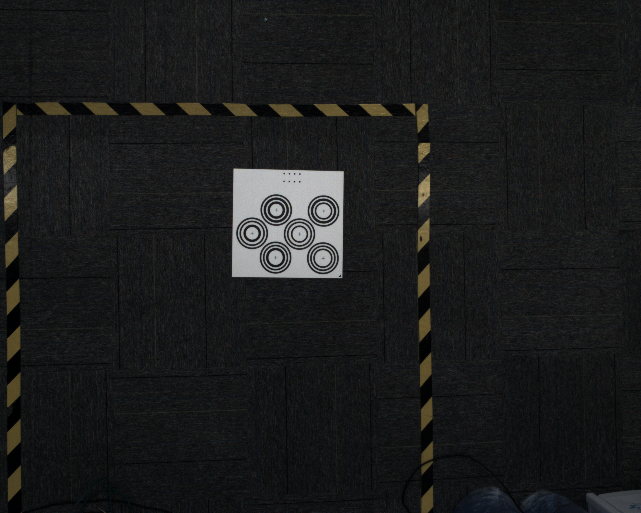
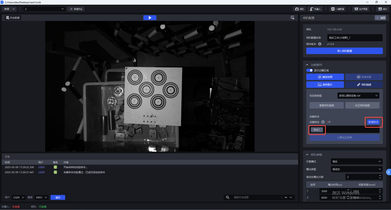
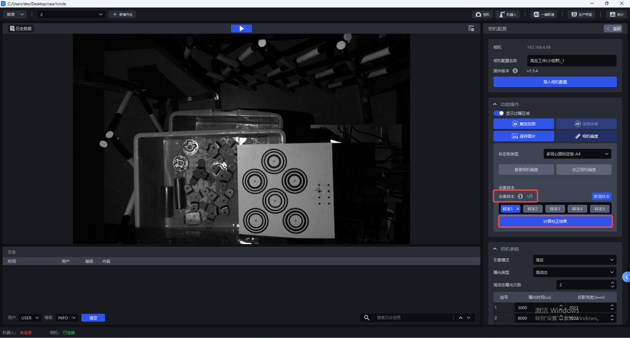
- Place the Calibration Board horizontally in the center of the Camera's field of view, click "Add Sample", and the Camera will start sampling and verifying the sample. If the collected sample passes the verification, it will be added under "Collect Sample", as shown in the figure below
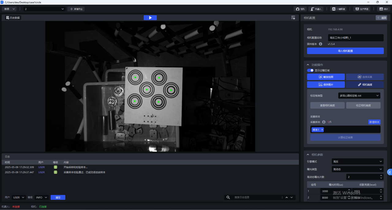
Click Sample x to view the collected samples. The centers of all concentric circles on the Calibration Board of samples that pass the verification turn green.
- Move the Calibration Board to the 4 corners within the Camera's field of view to add new samples
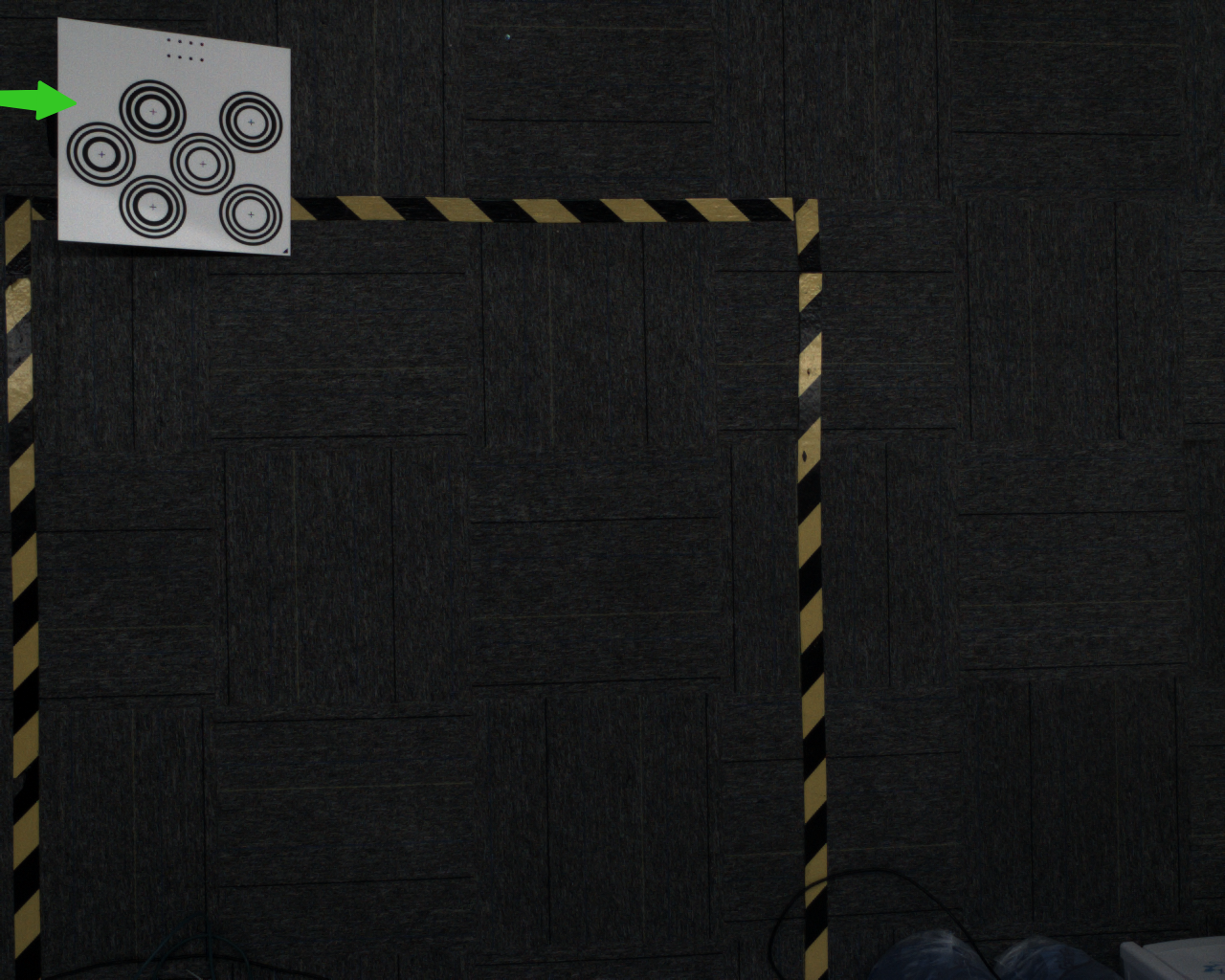
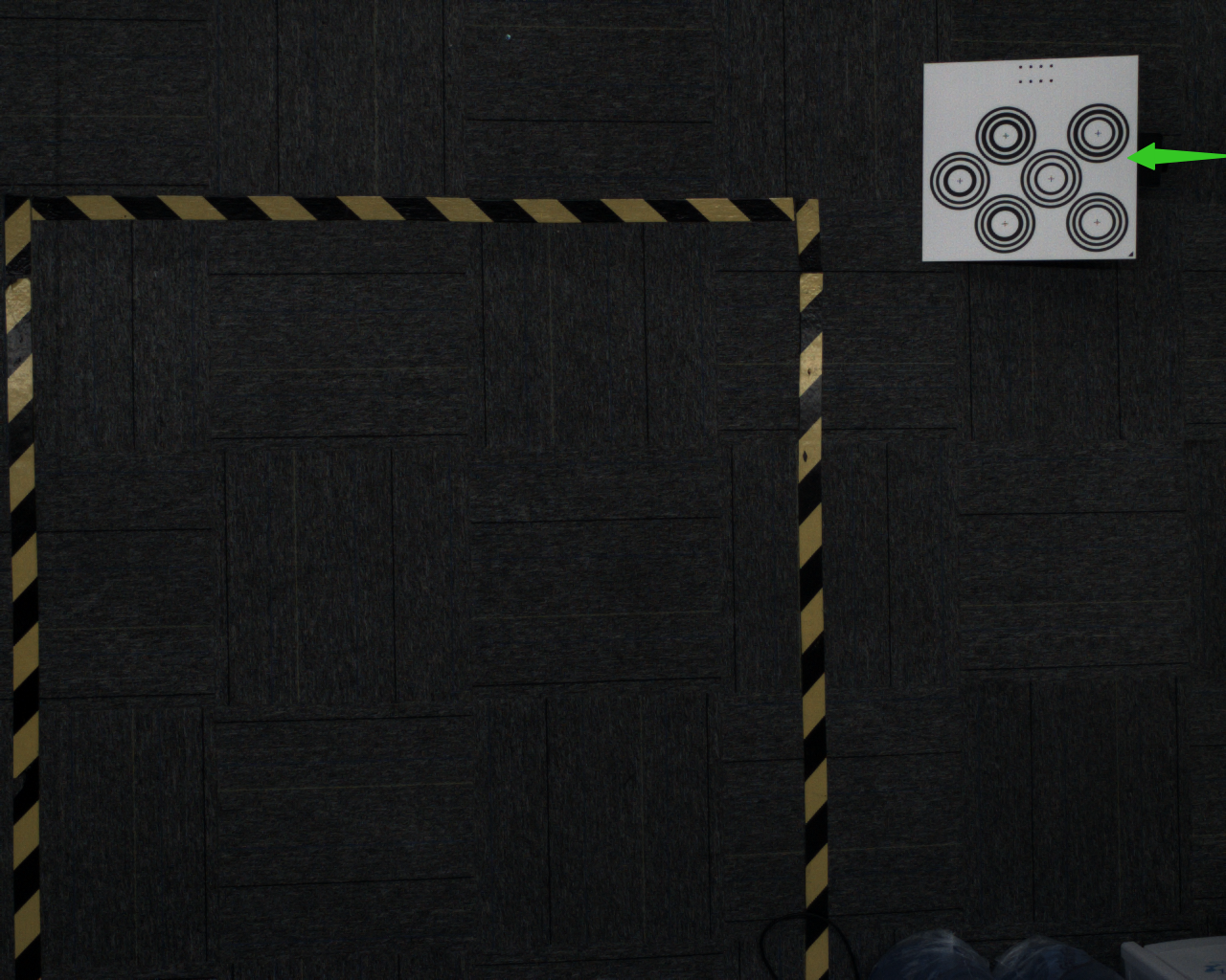
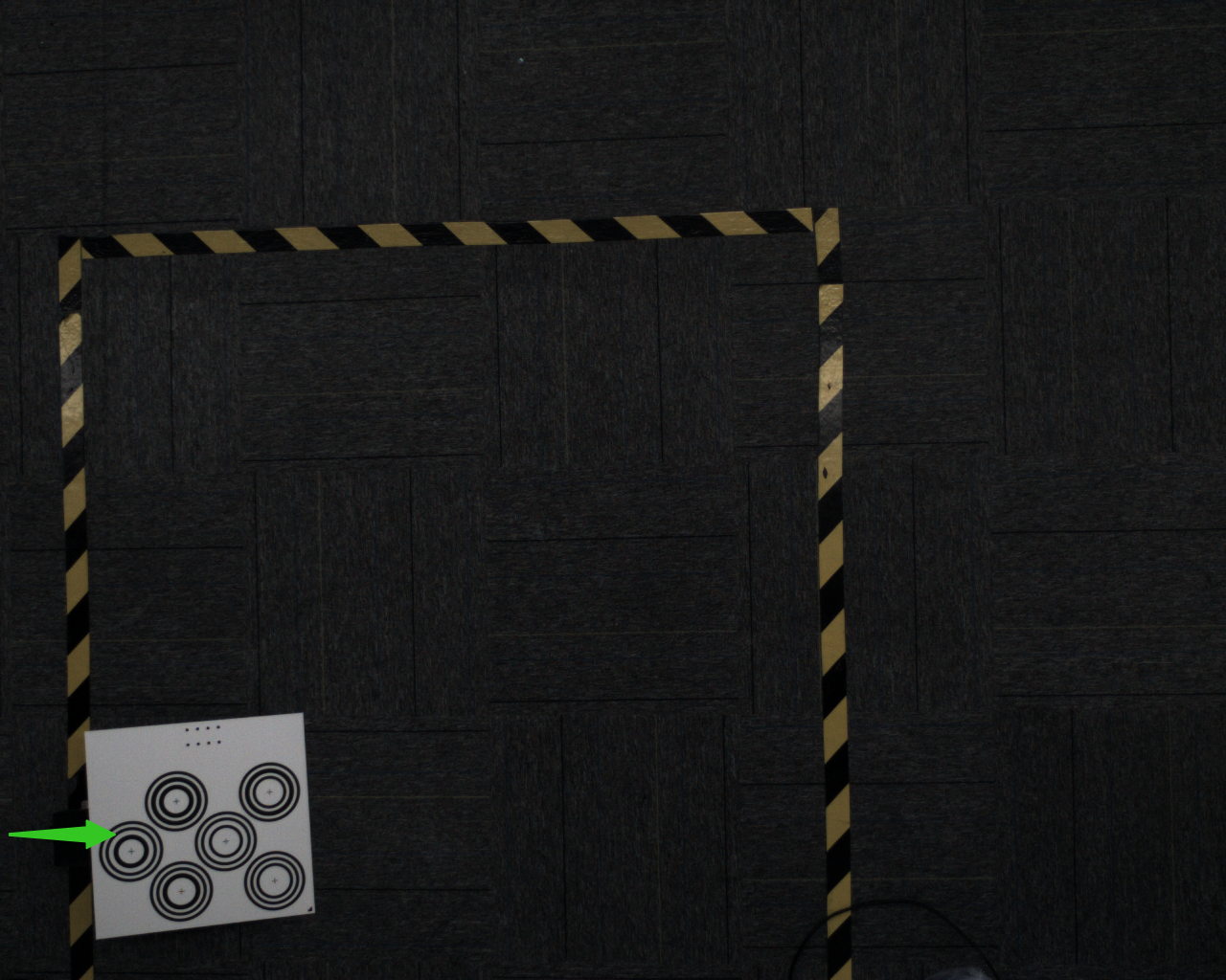
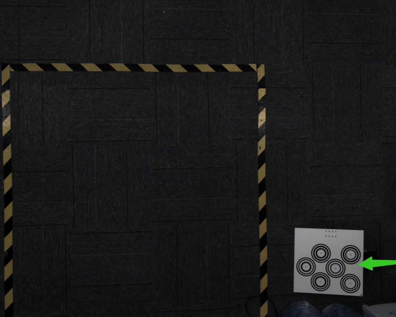
Place the Calibration Board at an angle at each corner. Place the Calibration Board at an angle of 15-30°. The tilt angle should not be too large or too small.
- After adding 5 samples, click
Calculate Correction Results
- After the correction is completed, a prompt box will pop up "Camera accuracy correction is completed. The correction accuracy is x and the error is normal. Do you want to overwrite the current CameraParameter configuration?"
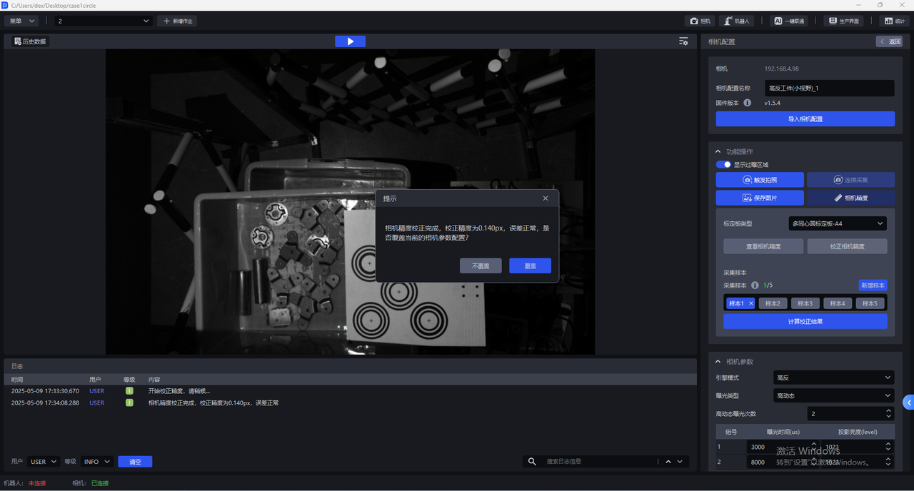
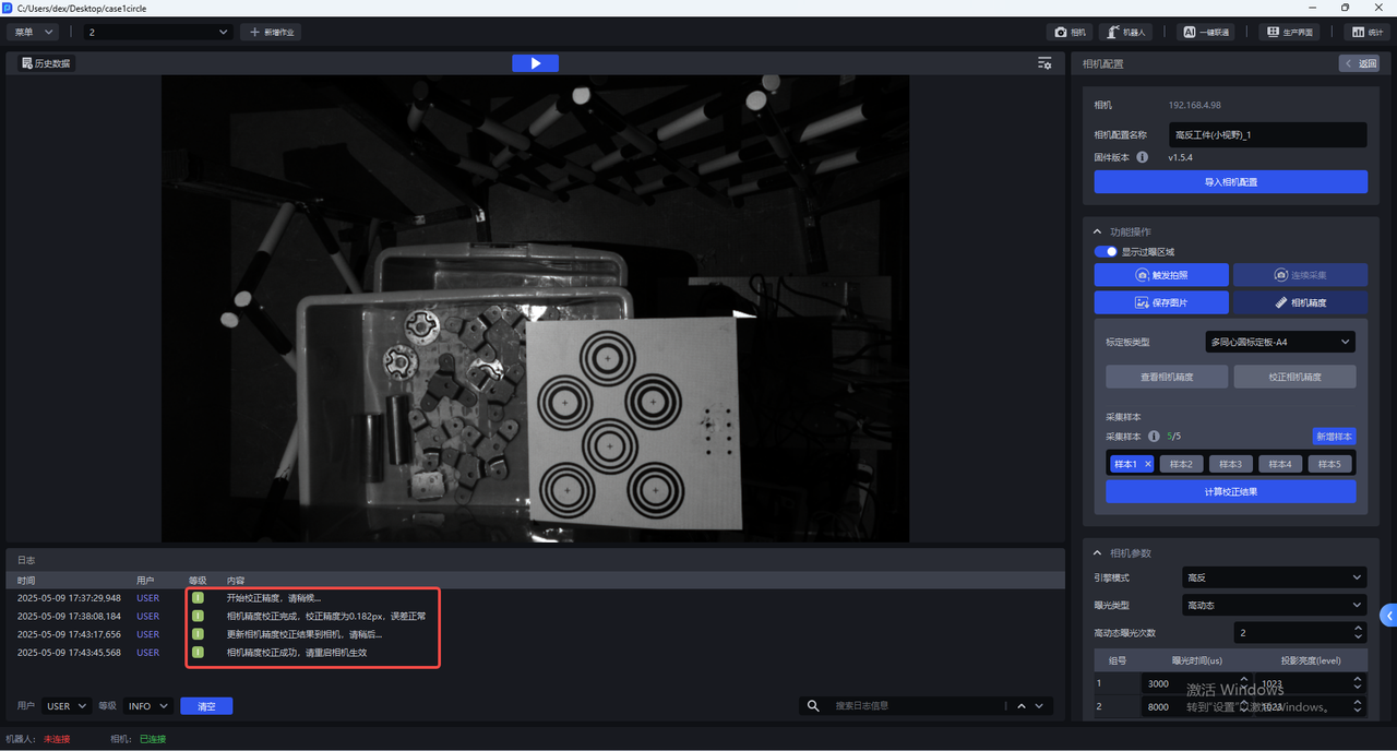
If you choose to overwrite the current CameraParameter configuration, the Camera accuracy correction results will be updated to the Camera, and you need to restart the Camera to take effect.
6. Camera parameter adjustment
Binocular Camera consists of two 2D Cameras. The deep learning model segmentation and recognition is based on the left eye image. The left eye image is preprocessed and input into the deep learning model.
6.1 Required Parameter
6.1.1 engine mode
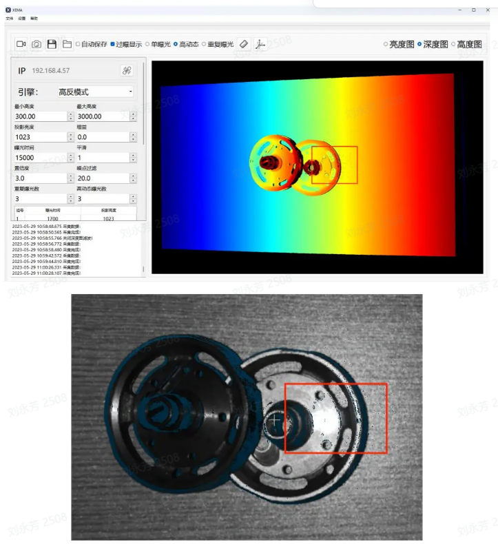
The engine modes include normal, high-reflective and black modes. The high-reflective mode is excellent for high-reflective parts, the black mode is excellent for black targets, and the normal mode can deal with ordinary targets.
| Engine Mode | Description |
|---|---|
| General | Applies to general Target |
| Highly reflective | Suitable for highly reflective Target |
| Black | Available for Black Target |
6.1.2 exposure type
(1) Single exposure
For ordinary texture Target, you can use single exposure
(2) High dynamics:
For highly reflective targets, you can use the HDR function for Point Cloud fusion.
Exposure type High Dynamics should be used in conjunction with Engine mode High Dynamics
High Dynamic Range Imaging (HDRI or HDR for short) is a set of technologies used to achieve a larger exposure dynamic range (that is, a greater difference between light and dark) than ordinary digital imaging technology.
High dynamic makes the image more distinct and the difference between light and dark obvious (especially when facing reflective targets).
Parameter adjustment suggestions:
- When using high dynamics, you can select the number of high dynamic exposures based on the specific Scene and Target. The value range is 2~6, and the default is 2. If the 3DPoint Cloud quality and 2D image quality are poor, the number of groups should be increased to expose the object multiple times to achieve the best imaging quality.
It is recommended to use fewer high dynamic exposures while meeting Point Cloud quality.
(3) Repeated exposure: The number of times the Camera needs to repeat shooting. The function is to improve the signal-to-noise ratio (the ratio of signal to noise). The higher the signal-to-noise ratio, the better. In this way, random noise will be suppressed and effective information will be increased. The value range is 0~10.
For black objects, you can use repeated exposure to optimize the Point Cloud through multiple exposures.
6.1.3 exposure time
Camera exposure time: Exposure time is the time it takes for the reflected light from the scene to reach the imaging photosensitive material through the lens and the shutter to open. The longer the exposure time, the more light comes in. If the exposure time is too long, overexposure will occur, which will affect the Point Cloud. The size should be adjusted based on the actual situation.
Range: 1700-100000
Exposure time and projection brightness are one group, and the number of high dynamic exposures is one group. Set the appropriate exposure time and projection brightness value for each group.
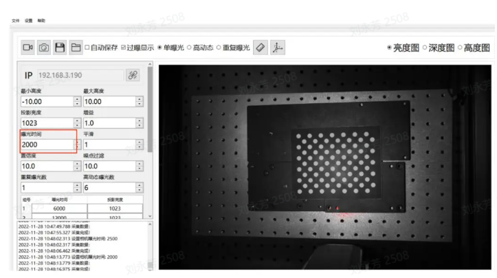
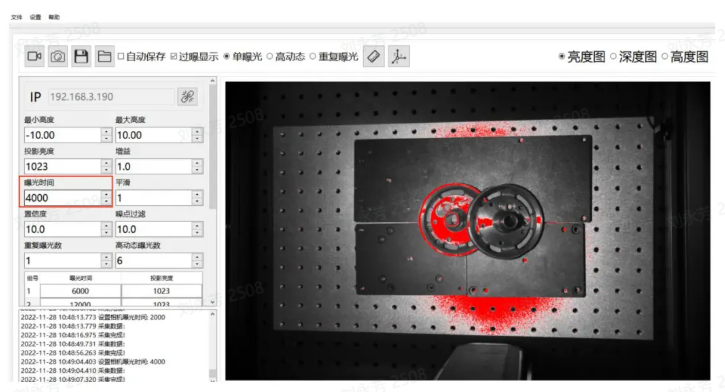
**Exposure time: **Exposure time is the time for light to enter the Camera when the Camera shutter is open. The longer the exposure time, the more light enters and the clearer the image.
If the exposure time is too long, overexposure will occur. You can turn on the display of the overexposure area. The red part is the overexposure area.
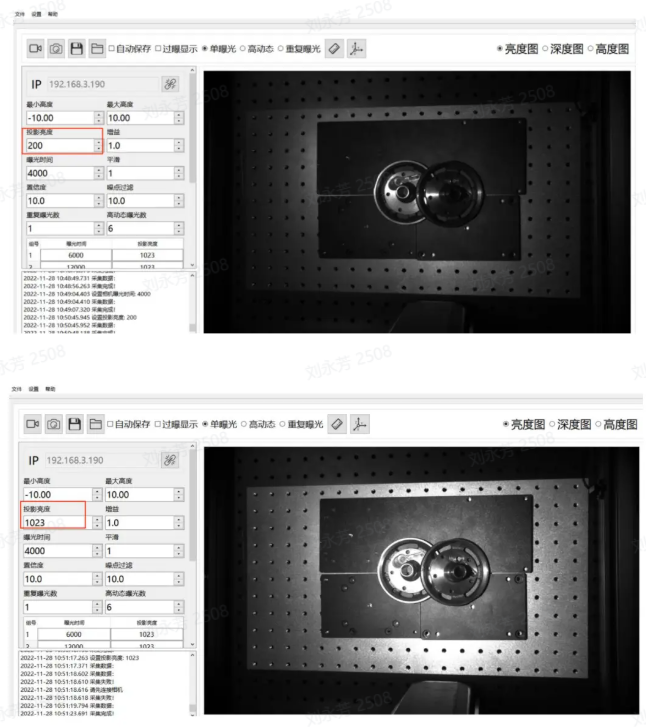
6.1.4 projection brightness
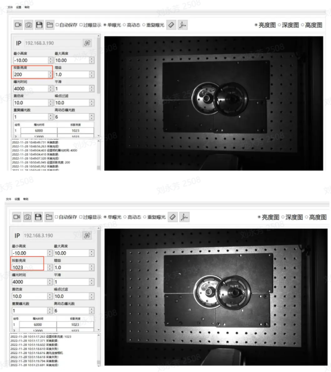
Projection brightness refers to the intensity of the projection light. The greater the light intensity, the brighter and clearer the image. Within a certain range, the human eye will feel that the image is clearer because of the high brightness. If it exceeds this limit, excessive brightness will make it impossible to see the image clearly.
Range: 0-1023
The larger the value, the brighter the projection, which can effectively improve the signal-to-noise ratio. It is recommended to use the maximum value. If the exposure time is still overexposed after adjusting it to the minimum, consider reducing the value.
Note: It is recommended to adjust the brightness to 1023
6.1.5 gain
Adjust the brightness of the picture.
Range: 0-24
The gain value of 2DCamera can be adjusted and should be increased appropriately. As the gain increases, the noise will increase accordingly.
6.1.6 smooth
Range:0-5
Smooth operations on Point Cloud
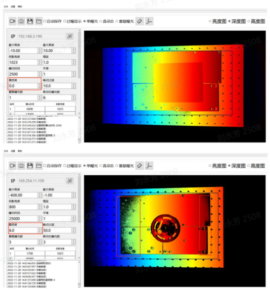
6.1.7 Confidence
Confidence indicates the degree of trustworthiness. Point Cloud will be screened initially, usually 2-5, and customers can adjust it on site.
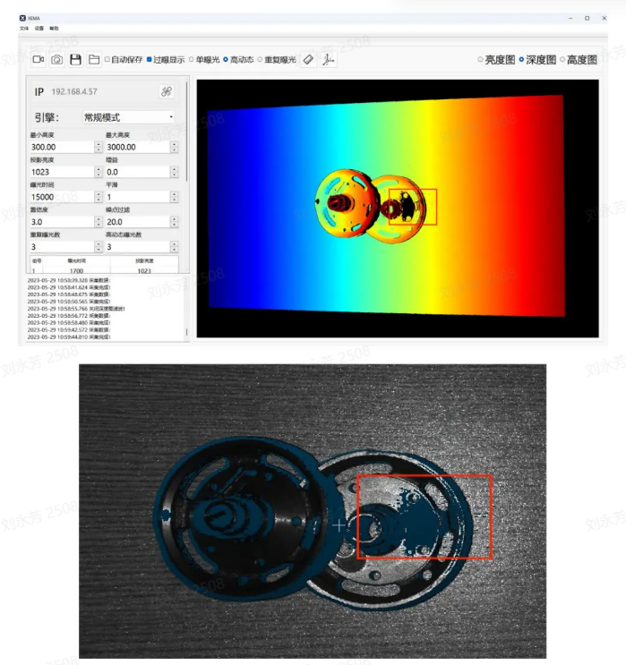
When Confidence is lowered, more of the black part in the Depth image is retained; conversely, when Confidence is raised, the black noise in the Depth image will be removed.
Range: 0-100
6.1.8 noise filter
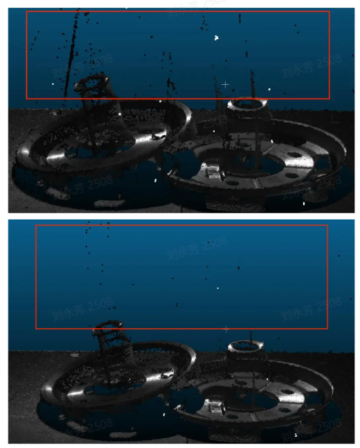
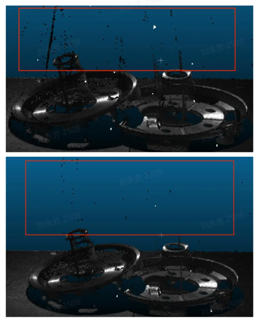
In the machine vision application scene, such as detecting metal, aluminum foil surfaces, reflective films, and smooth surface items, specular reflection will cause excessive local reflected light, thereby losing the original information of the object and interfering with machine vision detection. Noise filtering can partially eliminate the generated noise and preserve the original information of the object.
Range 0-100
When identifying items on metal, aluminum foil surfaces, reflective films, and smooth surfaces, specular reflection will cause excessive local reflected light, thereby losing the original information of the object and interfering with Pickwiz recognition and detection of images. Increasing the noise filter value can partially eliminate the generated noise and preserve the original information of the object.
6.2 Optional Parameter
6.2.1 radius filter
For each point in the Point Cloud, determine a sphere with a radius r and select the number of effective points. If the number of internal points is less than the effective points, it will be considered a noise point and will be eliminated. The smaller the radius and the larger the number of effective points, the more obvious the filtering effect will be.
Radius range: 0-99
Valid point range: 0-99
6.2.2 depth filter
For filtering suspended noise in the Z-axis direction, the larger the threshold, the more obvious the filtering effect. Based on the Depth image filtering method, the Threshold is recommended to be 33 at a distance of 1000mm.
Range: 0-100
6.2.3 reflection filter
Filter the facade noise caused by metal mutual reflection. The larger the threshold, the more obvious the filtering effect will be.
Range: 0-100
6.2.4 phase correction
Phase correction, namely Point Cloud grayscale compensation, is a method of correcting grayscale information in three-dimensional Point Cloud data. The purpose of Point Cloud grayscale compensation is to eliminate these grayscale value differences and convert the grayscale information in Point Cloud into a value corresponding to the reflectivity of the actual object surface. The larger the threshold, the more obvious the correction.
Range: 0-100
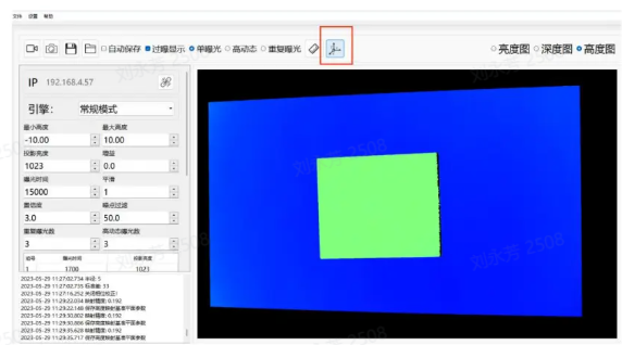
Instructions for use: First place the Calibration Board, using the plane of the Calibration Board as the reference plane. As shown in the picture above.
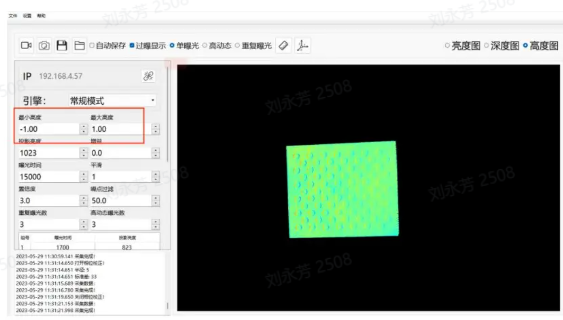
As introduced in the Maximum Height and Minimum Height section, adjust the maximum height to 1, adjust the minimum height to -1, and only display the Calibration Board part, as shown in the figure above.
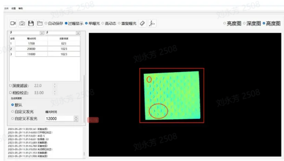
When phase correction is not turned on, the Calibration Board is as shown in the picture above. In the actual Calibration Board, the entire Calibration Board is flat, and there are no up and down fluctuations in the circular and non-circular parts. However, the actual photographed effect is that of a circle with undulations.
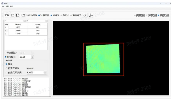
After turning on the phase correction, it is found that there is basically no color difference or the difference is not obvious on the Calibration Board, indicating that the correction is successful.
6.2.5 2D image overlay exposure
This function can separately cover the initial 2D image after obtaining the Point Cloud; sometimes the Point Cloud is good, but the 2D image is too dark and overexposure, which does not meet the requirements. At this time, the 2D overlay exposure can be turned on to cover the original 2D image.
If you choose Luminous, you can set the exposure time, gain, and shooting method (single exposure or high dynamic).
If you choose not to emit light, it depends on the light brightness in the environment. You can also set the exposure time, gain, and shooting method (single exposure or high dynamic) by yourself.
stack gain
When using the 2D stacked exposure function, you can adjust this gain to make the picture brighter.
Overlay exposure time
When using the 2D overlay exposure function, you can adjust this exposure time to make the picture brighter.
7. Typical cases
Camera parameter adjustment principle: Keep the target surface exposure uniform and the texture clearly visible. The parameter adjustment case takes 1024*1280 resolution as an example.

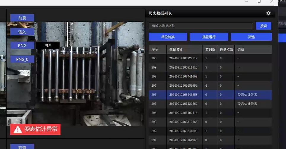
Case 1: Shanghai Industry Fair-Outdoor Sunlight Depalletizing
Scene features: ambient light changes suddenly, from indoor LED to direct sunlight (the picture below shows the change effect from unadjusted to adjusted)
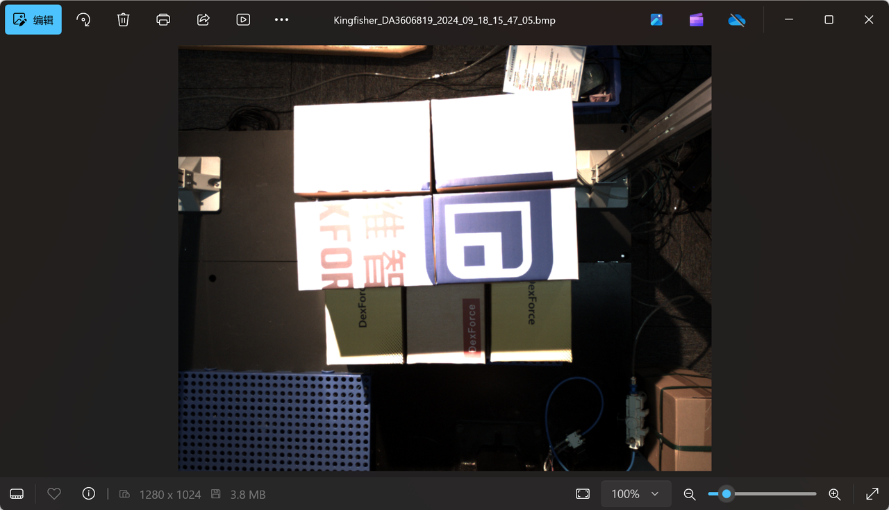
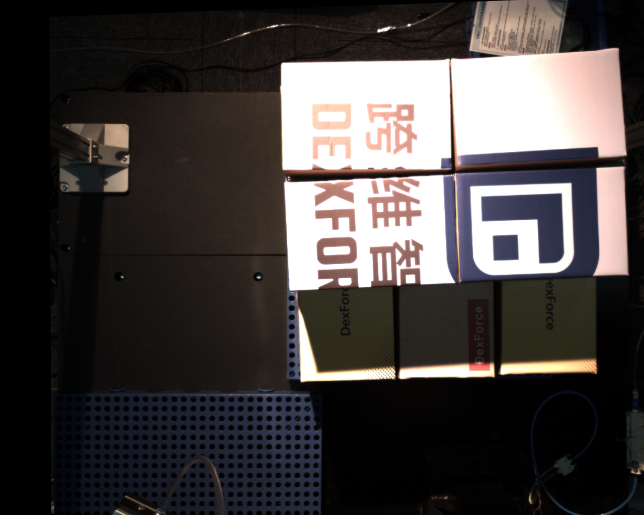
Parameter adjustment idea: To keep the imaging stable and the Cycle time unchanged after sudden changes in ambient light, use automatic exposure mode 2 (Haikang SDK comes with AOI automatic exposure) and modify the AOIParameter.
Case 2: Shanghai Industry Fair-Indoor Lighting Highly Reflective Rod
Scene features: The color of the spotlight light changes, but the brightness is almost the same
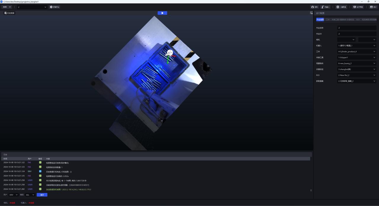
Parameter adjustment idea: just fix the exposure and lower the exposure value
Case 3: Luyuan Oil Cylinder-Semi-Outdoor Sunlight Highly Reflective Target
Scene features: There is a skylight above the head. Affected by the weather, the light intensity varies during the day and requires supplementary light at night (the picture below shows the adjusted effect)
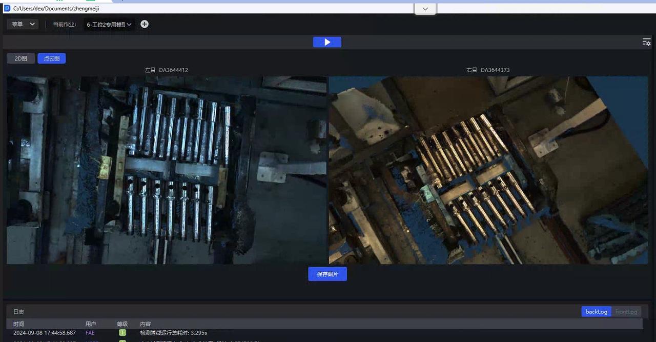
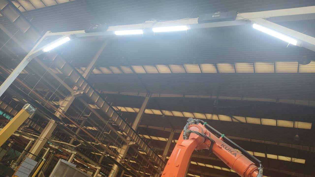
Parameter adjustment idea: No need to consider Cycle time, use PID automatic exposure, and adjust to the required brightness
Case 4: Destacking in Dezhou, Shandong Province-Tengyang
Scene characteristics: There is direct sunlight at three or four o'clock in the afternoon, causing partial overexposure of the stack surface (the picture below shows the HDR result)
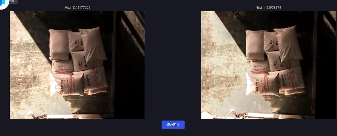
Parameter tuning approach: For a Scene with large changes in ambient brightness and white sacks, if Hikvision AOI auto exposure is selected, it is easily affected by the exposed bottom area. Therefore, pid auto exposure is selected and ExposureAuto is set to 3. Local direct sunlight causes severe overexposure, so HDR high dynamic synthesis is required and HDR is enabled. "HDREnable": 1. Based on the PID exposure multiplier. See the yellow marked part in Parameter for details. "HDR": "AutoExposureTimeRates", 0.1 is used because the sunlight is very strong and the exposure in bright areas needs to be reduced; 1 is the appropriate exposure value for normal adjustment; 1.5 is used to increase the brightness in dark areas.
Get to know the binocular camera
structure
The binocular camera consists of two 2D Cameras. The Extrinsic Parameter calibration file is used to illustrate the relative relationship between the two cameras.
The deep learning model segmentation and recognition is based on the left eye image.
The essence of parameter adjustment
The hardware is 2D, so what you need to adjust are parameters such as exposure and white balance of 2DCamera. Only when the exposure is adjusted well can the subsequent imaging quality and accuracy be guaranteed.
Introduction to related concepts
Baseline length: the distance between two Cameras (in layman’s terms)
Number of binocular Point Clouds: There are as many points as there are pixels, that is to say, the resolution is 3036*4024, and there will be tens of millions of Point Clouds.
rectify: baseline correction, the process of aligning two 2D RGB images, visualized as a red line image, you can see that the red line in the red circle passes through the same point on the two images
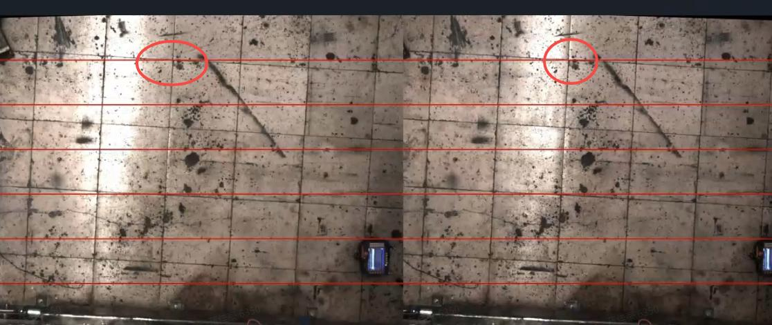
Parallax: On the 2D images captured by the two cameras, how many pixels are there between a point in the actual scene and the horizontal direction of the rectified 2D images for the left and right eyes?
calculation formula: disp = baseline length * CameraIntrinsic Parameterfx / distance from the object
Scale scaling ratio: The resolution 3036*4024 is multiplied by the scaling ratio 0.34, and the result is a picture close to the resolution of 1024*1280. The Intrinsic Parameter also changes during Inference.