Log description
1. Log storage location
(1) Log storage location of previous version of PickWiz V1.6.0
~/kuawei_data/log/middleware/middleware.log Some system logs in the backend except the detection process ~/kuawei_data/log/backend/backend.log Backend detection process log ~/kuawei_data/log/PickLightMicroServer/PickLight_deepmodel.log Model Inference Service Log ~/kuawei_data/log/glia/glia.log glia log ~/kuawei_data/log/rlia/rlia.log rlia log ~/.dexforce/log/pickwiz/app.*.log PickWiz Frontend Log
(2) Log storage location of PickWiz V1.6.0 and later versions
~/.dexforce/log/picklight/backend_sys/backend_sys.log Original middleware.log ~/.dexforce/log/picklight/backend_pipe/backend_pipe.log Original backend.log ~/.dexforce/log/picklight/backend_deepmodel/backend_deepmodel.log Original PickLight_deepmodel.log ~/.dexforce/log/glia/glia.log glia log ~/.dexforce/log/rlia/rlia.lAog rlia log ~/.dexforce/log/pickwiz/app.*.log PickWiz Frontend Log
(3) Log storage location of PickWiz 1.7.1 and later versions
~/.dexforce/log/pickwiz/PickWiz_INFO_年月日-时分秒.进程ID PickWiz Frontend Log
2. Introduction to log function
| field | Description |
|---|---|
| time | log generation time, PickWiz supports real-time viewing of logs. |
| level | log content level, DEBUG represents all log information, including detailed debugging information, used to troubleshoot problems; INFO represents the log of the system's regular operation, including the running process, alarm information and error information; WARNING represents alarm information, including alarm information and error information; ERROR represents error information. You can filter the log content at the bottom level . |
| Content | The specific content oflog |
| Clear | clears all logs displayed on the current interface. The log storage file will not be cleared. If you need to view the cleared logs, please refer to 1. Log storage location Open the corresponding log storage file. |
| Copy | keyboard Ctrl+C/Ctrl+V or Right-click Copy to copy the log information, as shown in the figure below.  |
| Search for | Enter the information in the log search box and click to search🔍 The icon can search for the corresponding information in the log, and can be quickly displayed one by one up and down.  |
3. Log content
3.1 data source
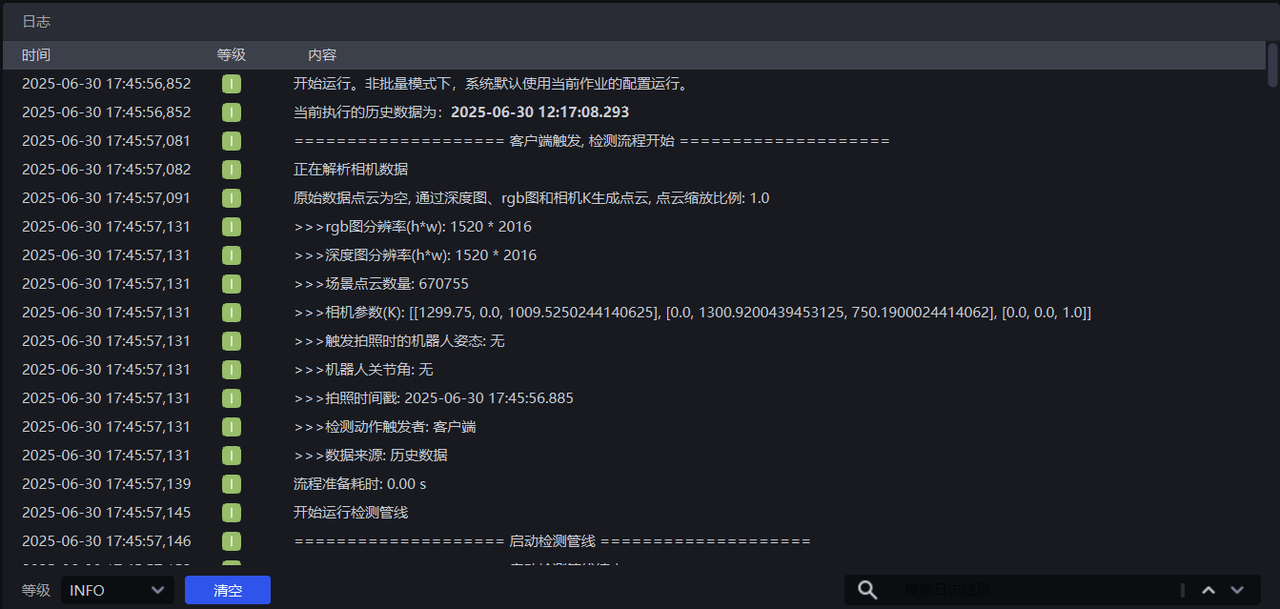
The beginning of the log identifies the source of the data input into the workflow.
If Camera data is selected in Visual Computing Configuration-Data Source, you need to connect to Camera and PickWiz A photo capture instruction will be sent to the Camera, and the Camera will collect 2D images, Depth images and generate Point Cloud images in real time.
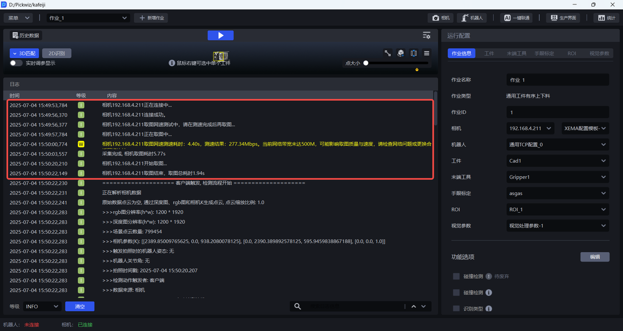
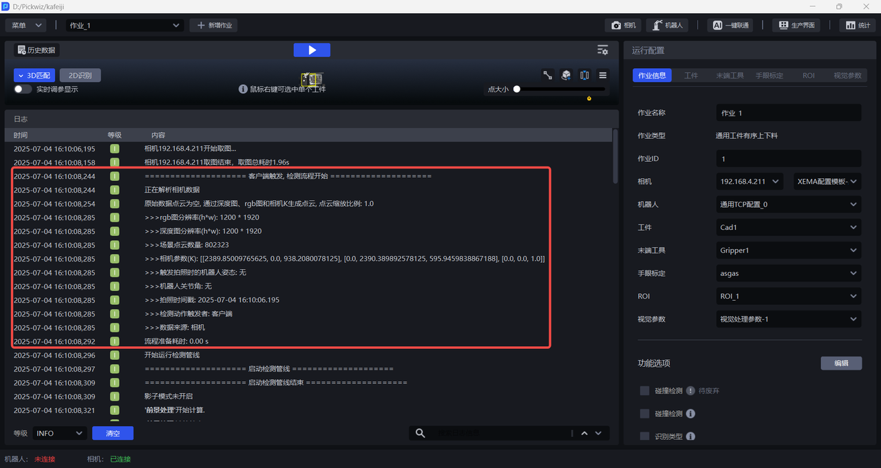
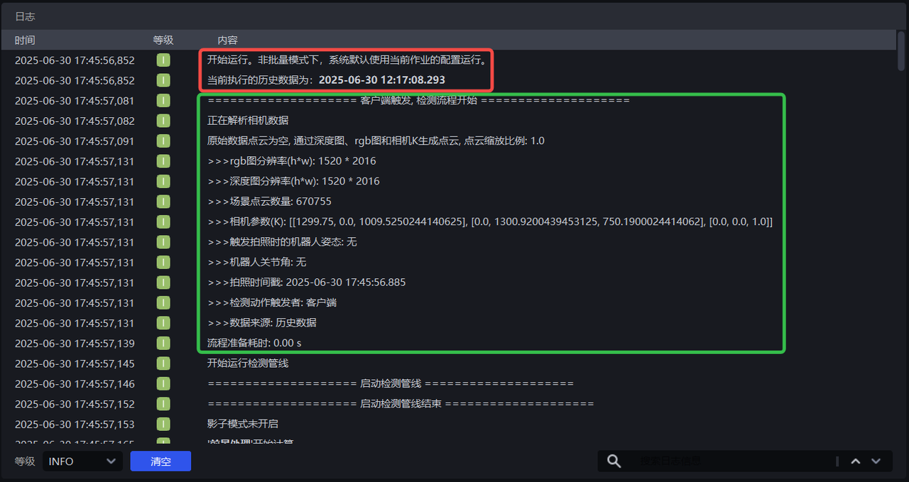
As shown in the figure below, after the Camera is successfully connected for the first time, it will first conduct a network speed test, and then take the actual photo and image capture. The actual photo and image capture takes 1.94 s. After the photo is taken, the real-time collected Camera data is analyzed, including the following Parameters.
RGB image resolution: the size of the 2D image. The calculation method is h (length)* w (width), and the unit is pixels;
Depth image resolution: The resolution of the Depth image, calculated as h (length)* w (width), unit is pixel;
Number of ScenePoint Clouds: Generate ScenePoint Clouds based on the 2D image, Depth image and CameraIntrinsic Parameter and input them into the workflow;
CameraParameter: CameraIntrinsic Parameter;
Robot posture when triggering the photo: the posture of RobotEnd-effector;
Robot joint angle: The representation method of Robot posture, generally expressed by Euler Angles, selected in Robot configuration;
There is also a photo timestamp: the time when the photo was taken;
Detect action trigger: if PickWiz The detection process triggered is the client. If the detection process is triggered by Robot, it is Robot;
Data source: Camera data or historical data. Please refer to the explanation of data sources. Visual Computing Configuration Operation Guide
If historical data is selected in the Visual Computing Configuration - Data Source, there is no need to connect to the Camera, and you can directly parse the Camera data saved in the historical data. This process takes 0 time, as shown in the figure below.
3.2 startup detection
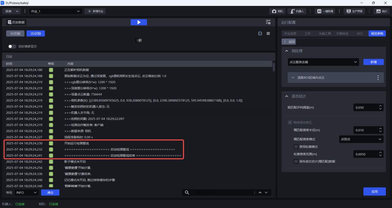
After data parsing, start the detection pipeline
3.3 foreground processing
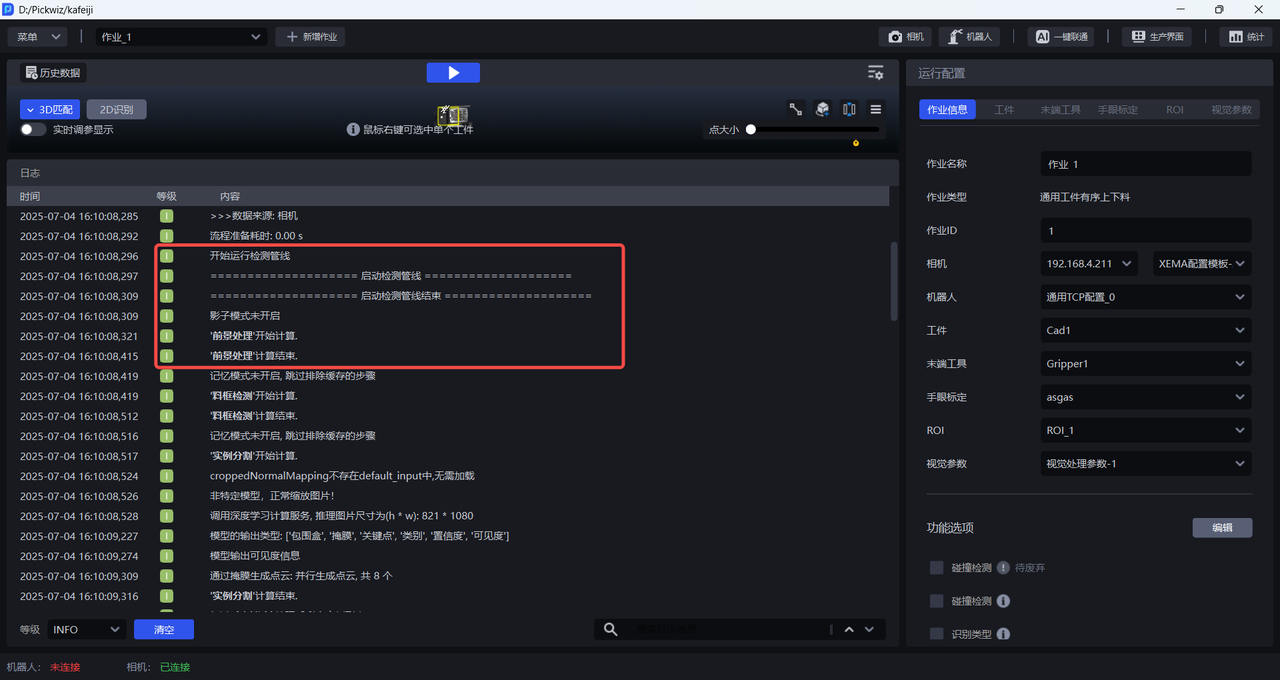
Foreground processing is the preprocessing of Camera data input into the workflow. If the visual Parameter-2D preprocessing adds a function, the 2D preprocessing function processes the 2D graph, Depth image, and ScenePoint Cloud at this node.
3.4 material frame detection
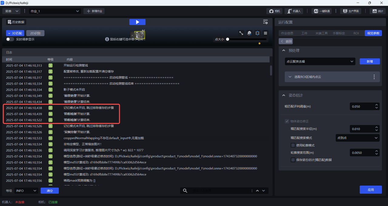
If there is a Scene Object such as a material frame in the Scene, this node will detect the material frame.
3.5 Instance Segmentation
Instance Segmentation refers to segmenting instances from Scene, which corresponds to visual Parameter-2D recognition-Instance Segmentation.
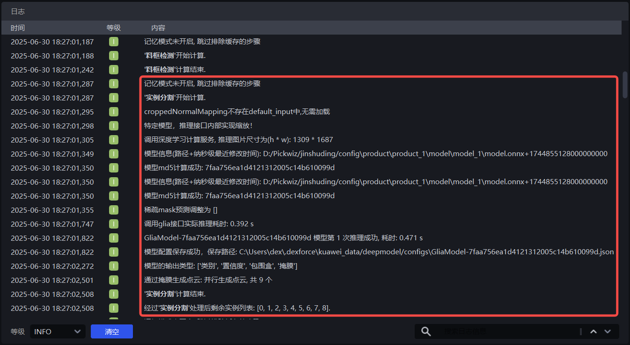
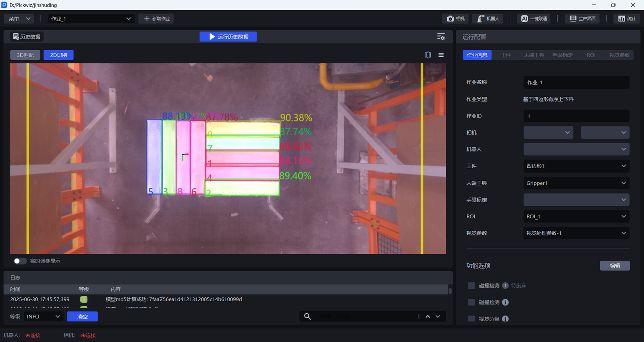
As shown in the figure below, 9 instances are segmented from the Scene, and a Point Cloud of 9 instances is generated based on the mask.
3.6 instance filtering
Instance filtering refers to filtering the segmented instances, which corresponds to visual Parameter-2D recognition-instance filtering.
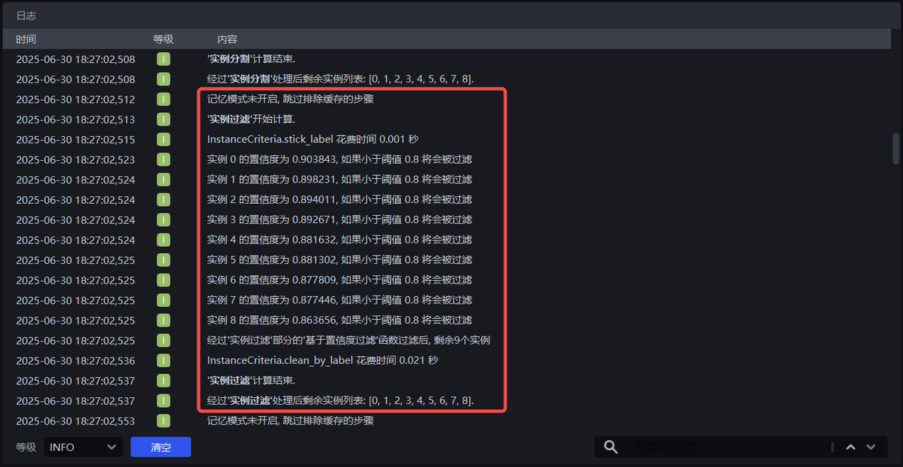
As shown in the figure below, if the Confidence of the instance is less than 0.8, it will be filtered. The Confidence of the 9 instances is greater than 0.8, so no instance is filtered.
3.7 instance sorting
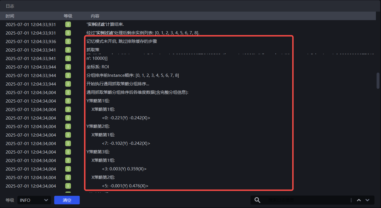
Instance sorting refers to grouping and sorting filtered instances. The grouping sorting method corresponds to the visual Parameter-2D recognition-instance sorting.
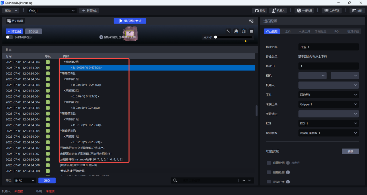
3.8 pose estimation
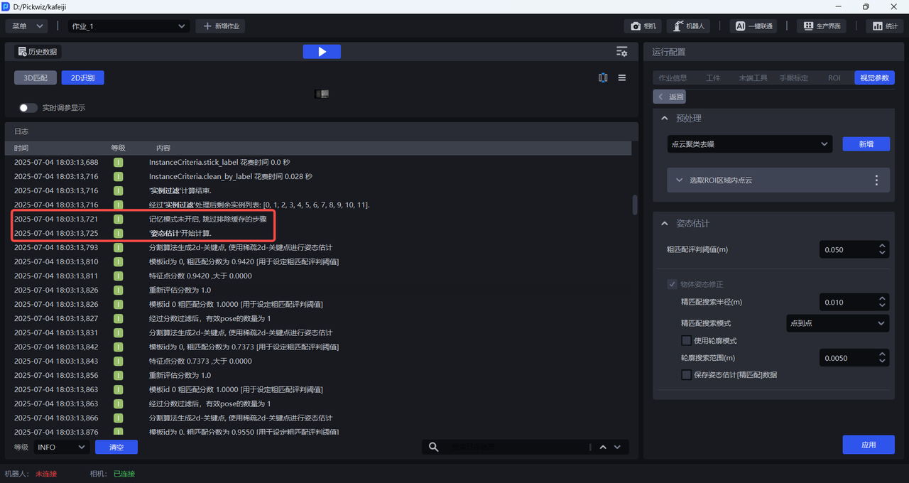
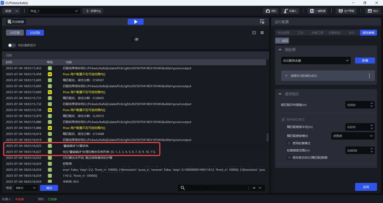
This node describes the method of calculating Target's attitude, which corresponds to the visual Parameter-3D calculation-attitude estimation.
As shown in the figure below, 3D registration performs Coarse Matching and Fine matching between ScenePoint Cloud and Point Cloud templates.
3.9 Pick Point generation
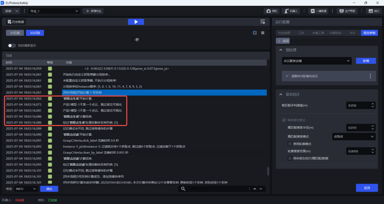
This node describes the Pick Point generation method, inputs the attitude estimation results, and outputs the Pick Point generated on each instance.
3.10 Pick Point filter
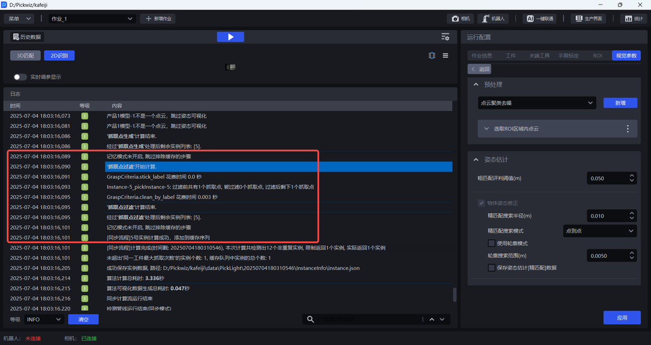
This node describes the method of filtering Pick Points, inputs all generated Pick Points, and outputs the filtered Pick Points, corresponding to the visual Parameter-Pick Point processing-Pick Point filtering.
3.11 Pick Point sorting
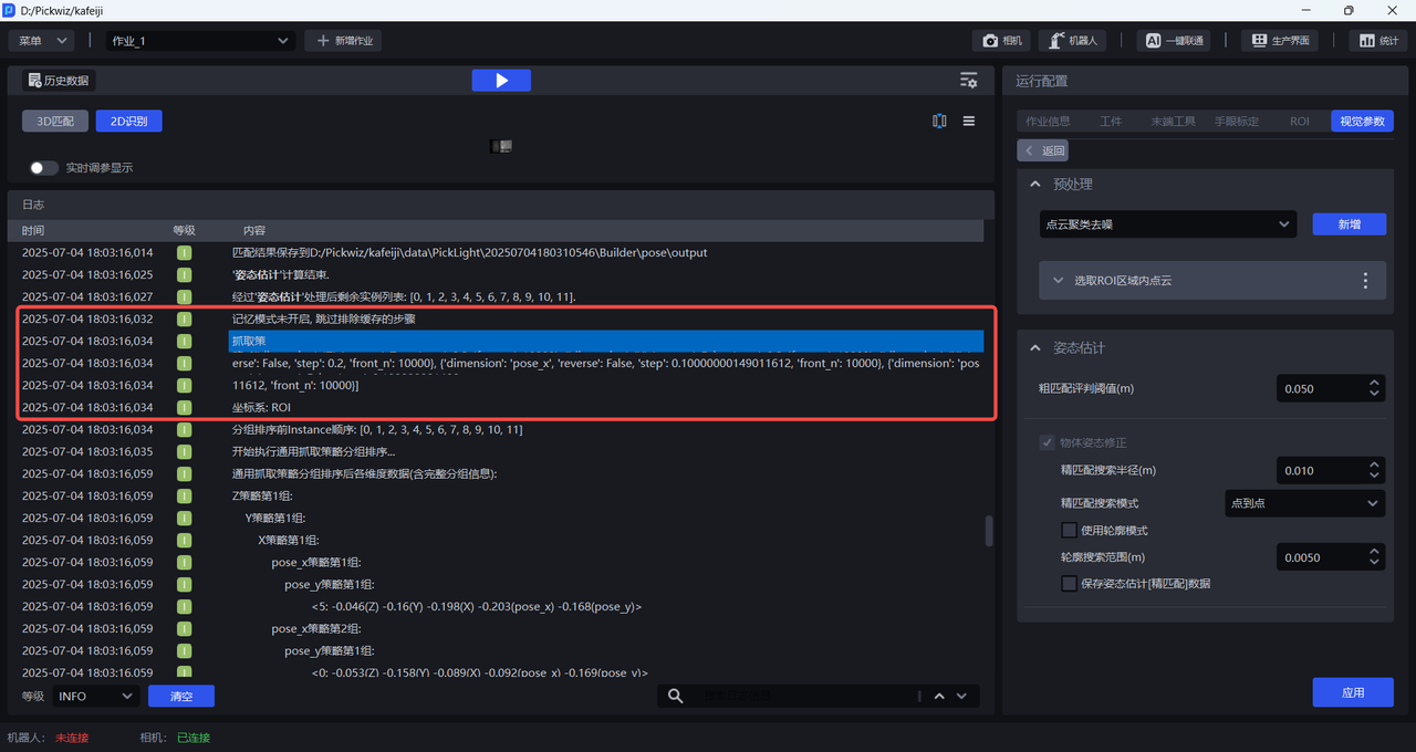
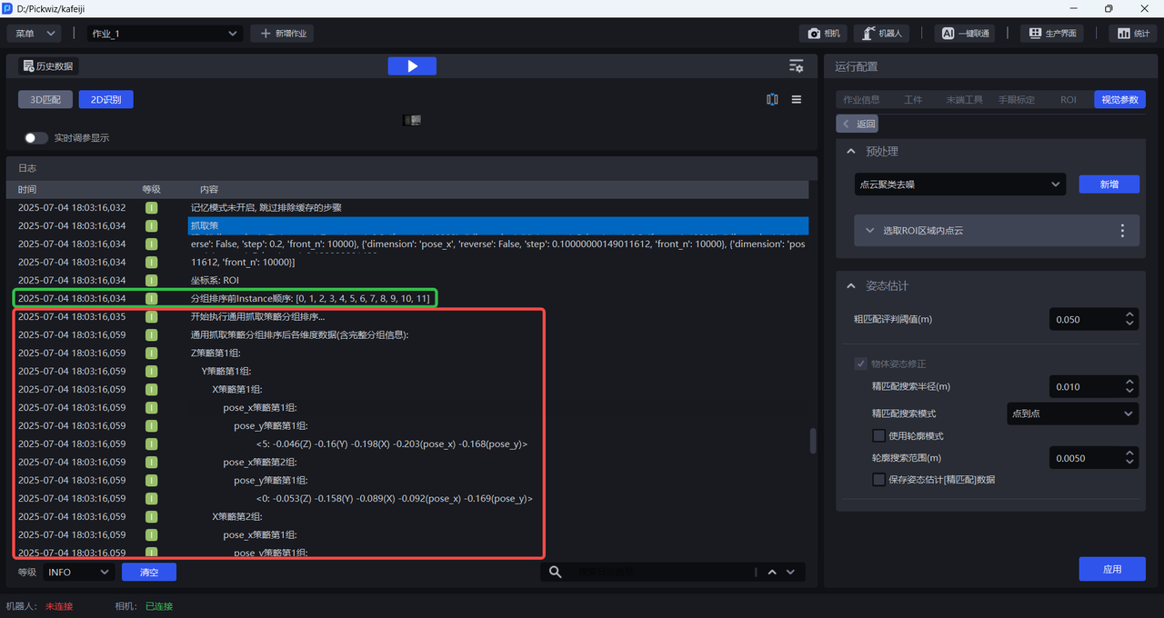
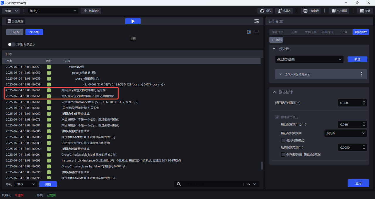
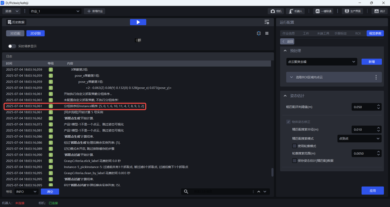
This node specifies the Pick Point sorting strategy, inputs the Pick Point generated after attitude estimation, and outputs the Pick Point after grouping and sorting. The grabbing will be carried out in this order when grabbing, which corresponds to the visual Parameter-Pick Point processing-Pick Point sorting.
3.12 detection completed
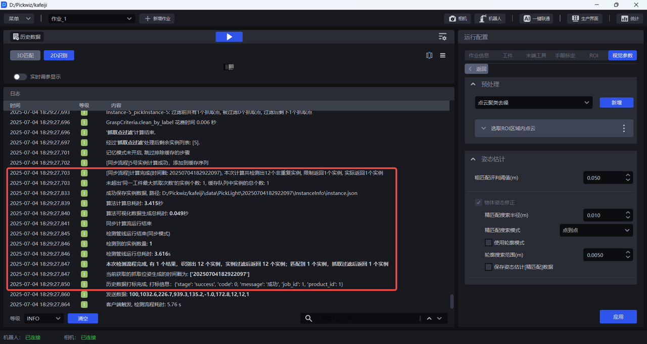
After the detection is completed, the node states the number of instances segmented, the number of instances returned after instance filtering, the number of instances matched by pose estimation, the number of instances returned after Pick Point filtering, and the time-consuming situation.
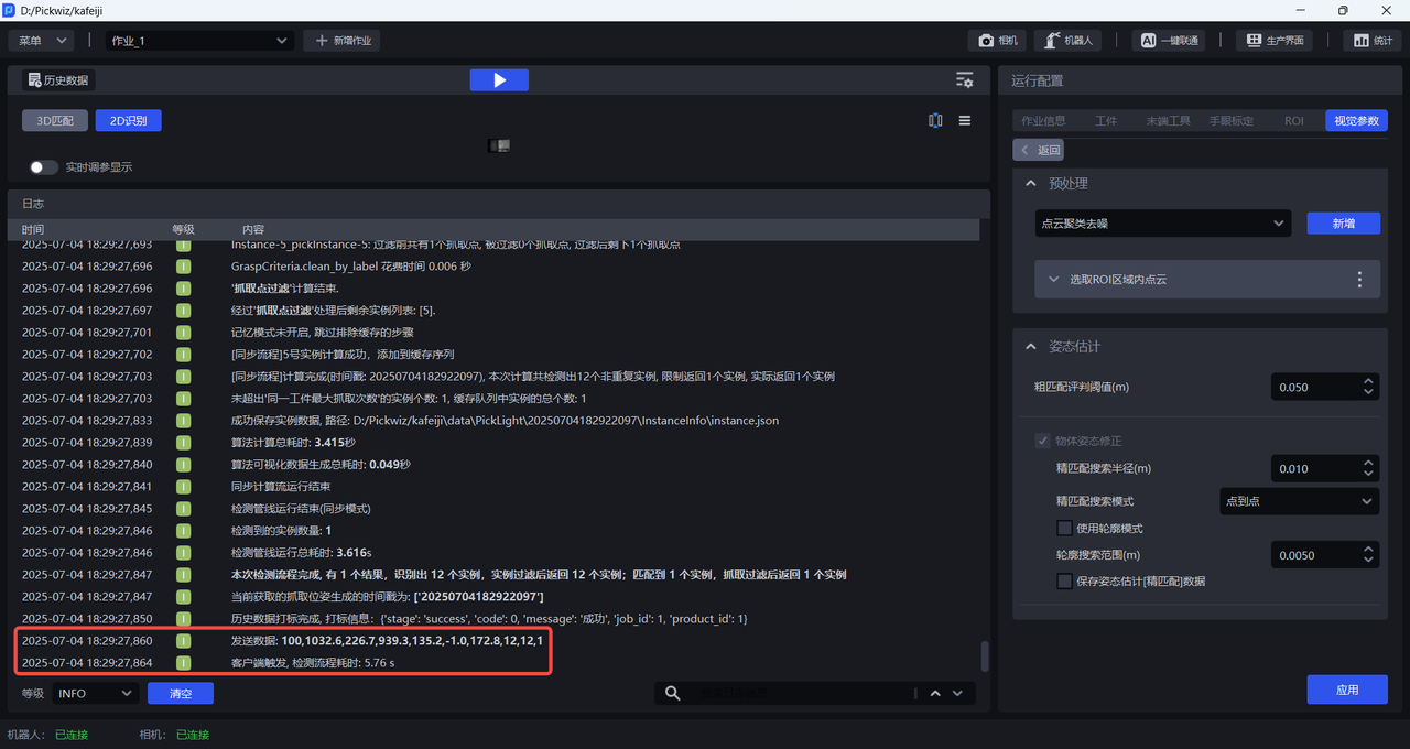
3.13 sent to Robot
PickWiz Send Pick Points to Robot. If the visual computing configuration - the number of sent instances is set to be greater than 1, then Pick Points of multiple instances are sent to Robot each time; if the visual computing configuration - the number of sent Pick Points is set to be greater than 1, then multiple Pick Points of one instance are sent to Robot each time.