Identify and capture FAQs
1. Binocular
Binocular windows PickWiz deployment (application direction)
1.1 It takes too long to take pictures under automatic exposure.
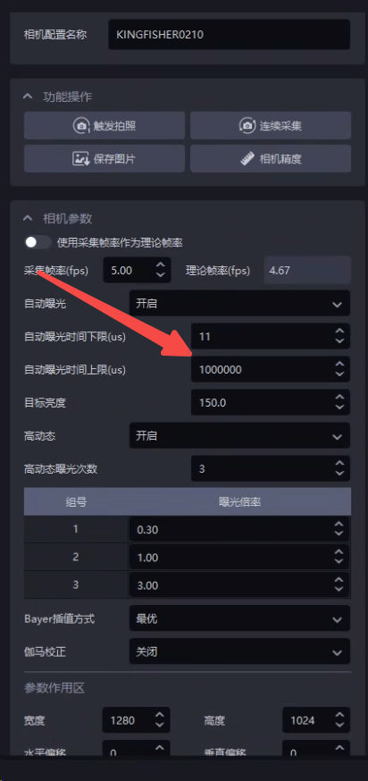
Question: When using a binocular camera, in automatic exposure or magnification-based HDR mode, how to further optimize the camera cycle time [≥1.7.1]:
**Solution:**Use the upper limit of the automatic exposure time to control the maximum exposure time of a single picture (it is recommended to set it to greater than 200000μs, that is, 200ms. If it is lower, it will not increase the frame rate. The maximum frame rate is 5 frames, but it will damage the image quality). 200000μs is the fastest Cycle time, the algorithm will automatically compensate the brightness according to the gain. The overall effect remains unchanged, but the image acquisition time is reduced. In HDR mode, the maximum exposure time can also be controlled through this Parameter, thereby reducing the overall HDR time.
1.2 crashes when taking pictures
Problem: When using binocular camera, taking photos will crash.
Possible reasons: Binocular Camera does not use Gigabit network
Solution: Binocular Camera must use Gigabit network. First check whether the network cable is Gigabit network. If not, it needs to be replaced.
1.3 Image acquisition failed and error reported
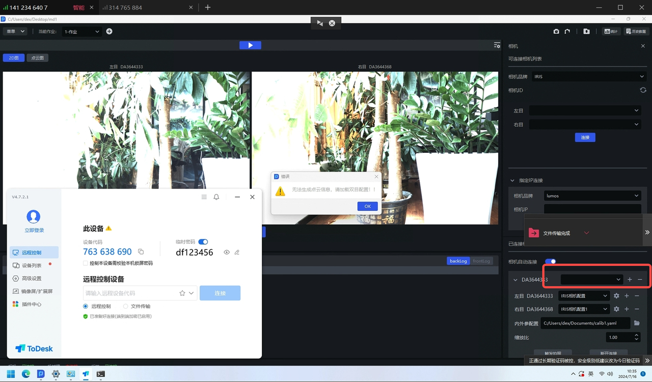
Problem: Binocular Camera reports an error and fails to take pictures
Solution: You need to create a new binocular Camera configuration and then take pictures.
1.4 Image acquisition failed and error reported
Problem: Binocular Camera reports an error and fails to take pictures
**Possible reasons:**Severe packet loss
Solution:
You can use MVS software to connect to the binocular camera and start collecting. Check whether there is a pop-up window indicating serious packet loss.
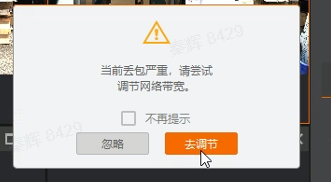
If so
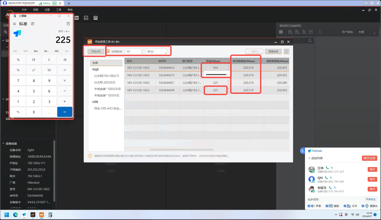
Ensure that the Camera switch is exclusively used by the Camera to ensure its network stability, and the Camera exposure is set to 5000 to facilitate subsequent bandwidth testing;
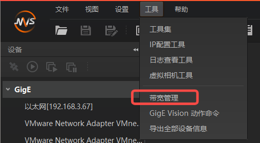
Open the bandwidth management tool and connect to the Camera you want to use;
Confirm the maximum network bandwidth: Slide the Camera bandwidth to the maximum and confirm the maximum value, such as 964M. After testing, a portion of the bandwidth (tentatively 64M) needs to be left, and the total available bandwidth is 900M;
Allocate bandwidth according to the number of devices used: If 4 Cameras need to be used at the same time, set the Camera bandwidth to 900/4=225M;
Click to start analysis. If the bandwidth (amount of data sent) is not full or the Camera is losing packets, you need to continue to locate the cause;
1.5 Point Cloud exception
Issue: Binocular CameraPoint Cloud imaging collapse/distortion
Possible reasons: 2D imaging is overexposed/overdark, the long direction of the Target is not perpendicular to the screen, and there is a visual blind spot
Solution:
- Prioritize checking whether there is overexposure/overdarkness in 2D imaging, and if so, prioritize exposure adjustment.
| status | 2D picture | Point Cloud | Remarks | processing method |
|---|---|---|---|---|
| Before adjusting the exposure (too dark) | 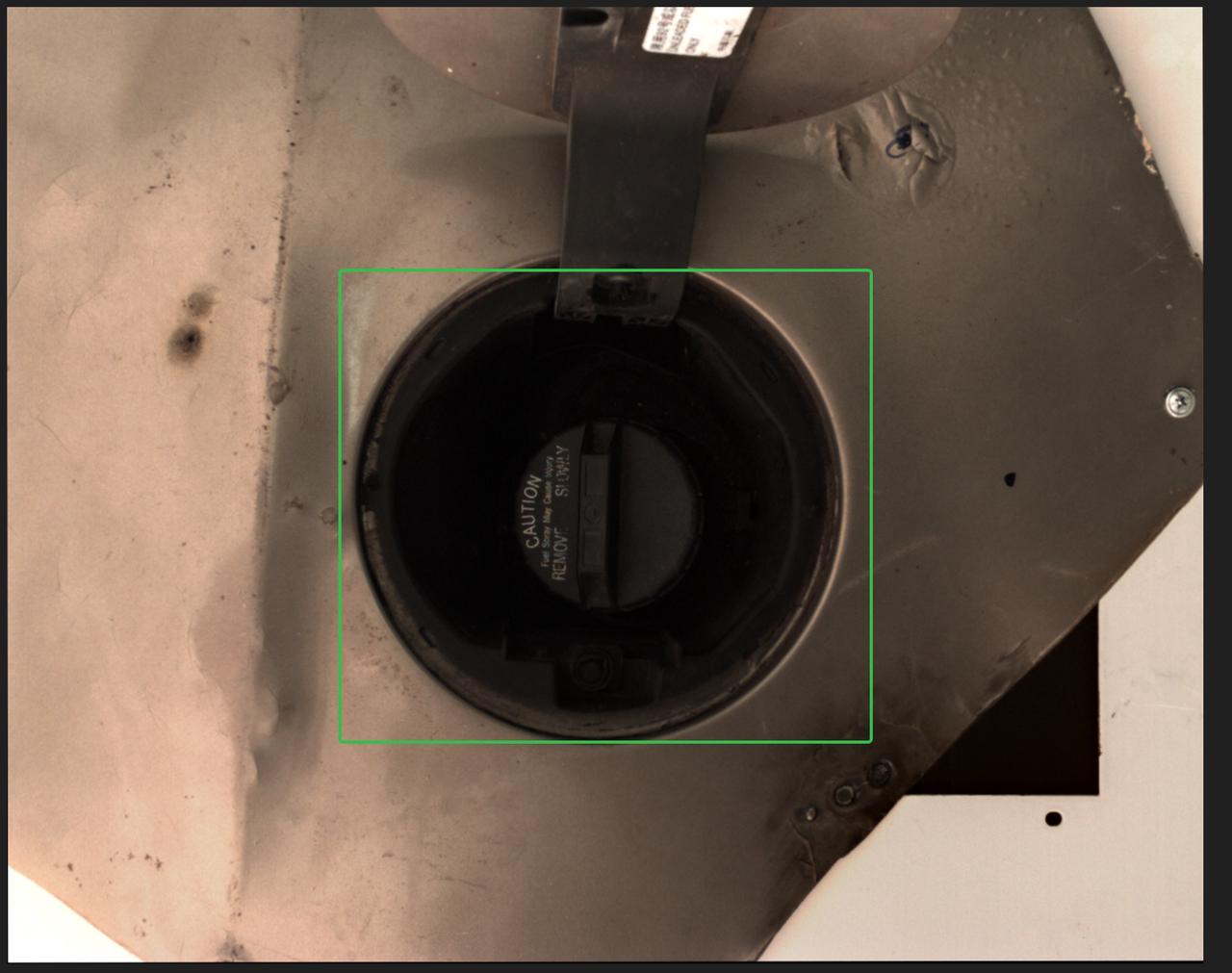 | 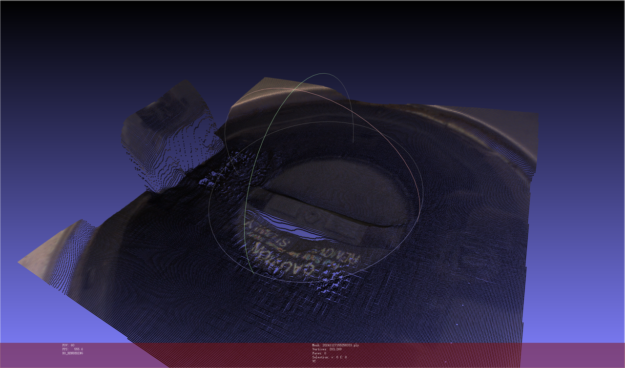 | collapse | supplementary light source makes the surface of Target Object clearly visible |
| After adjusting the exposure | 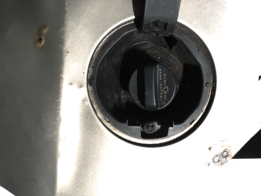 | 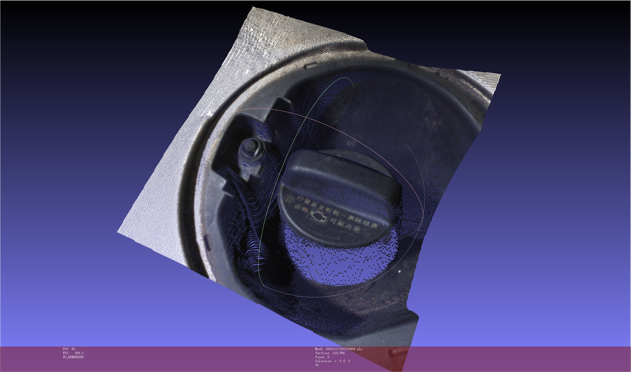 | Normal | / |
| status | Point Cloud | Remarks | processing method |
|---|---|---|---|
| Before adjusting the exposure (too dark) | 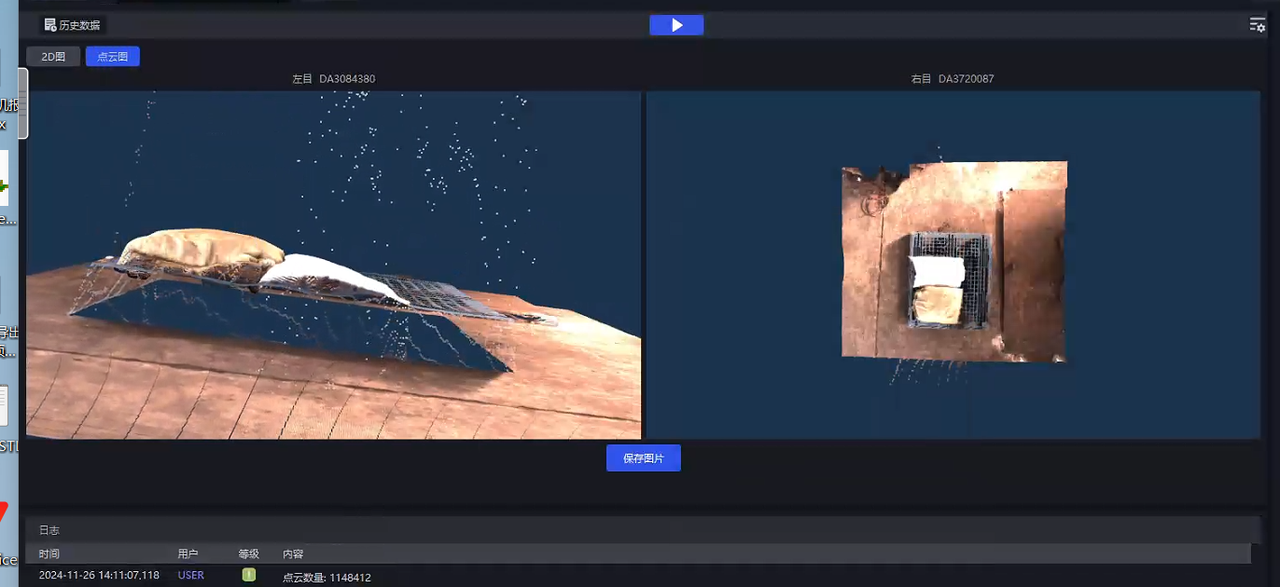 | collapse | 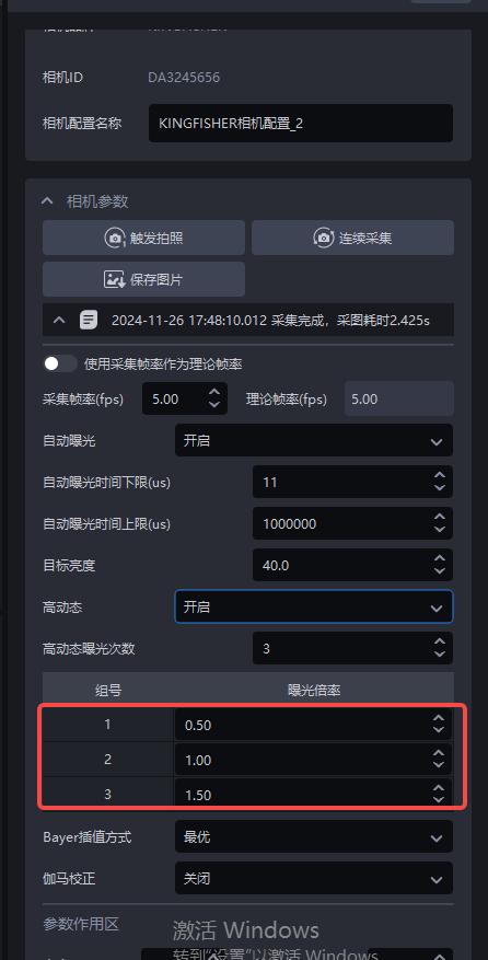 |
| After adjusting the exposure | 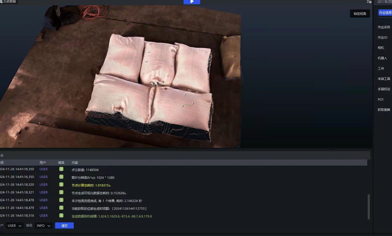 | Normal | / |
Check whether the long direction of the target is perpendicular to the screen. This involves the principle issue of "same point" for binocular vision. It is recommended to flip the camera installation angle by 90 degrees, as shown below.

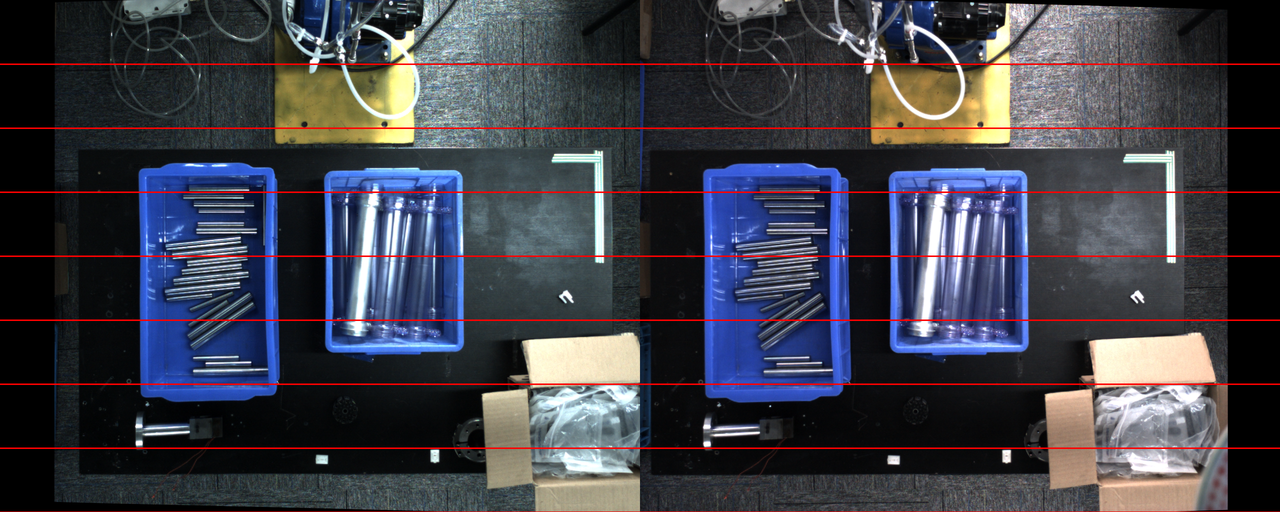
If the object has "visual blind spots" in the left and right images of the image, the model will not be able to predict the Point Cloud correctly, causing distortion or collapse.
**How do you understand this visual blind spot? Only one Camera can capture it? **: Can be seen with the left eye but not with the right eye (vice versa) Why "cannot be solved on the model": The general way to solve this problem is shadow mode, but this area happens to be an occluded area, and this area will not enter shadow mode learning. Therefore useless.
Examples Imaging 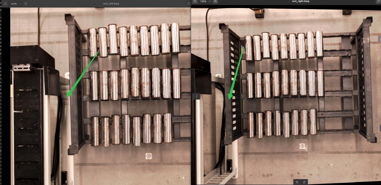
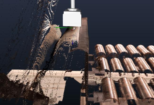
If the red line image is normal but the Point Cloud imaging is abnormal, then modifying the zoom ratio and the minimum distance of the object from the Camera can form a normal Point Cloud. In fact, the minimum distance of the object from the Camera should be modified first.
| example | red line chart | Point Cloud |
|---|---|---|
| exception | 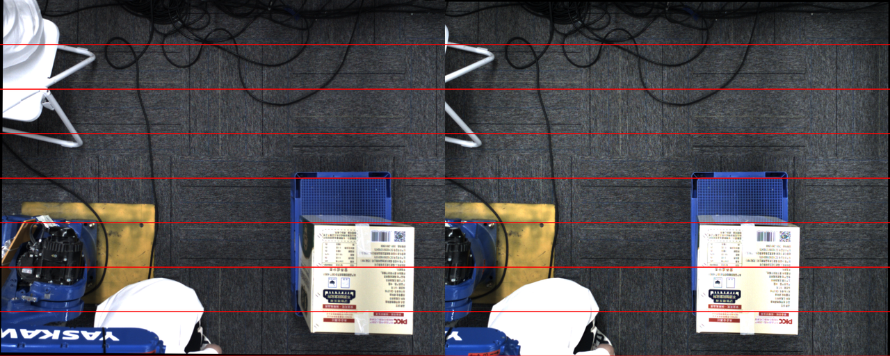 | 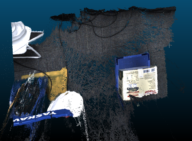 |
| Normal | 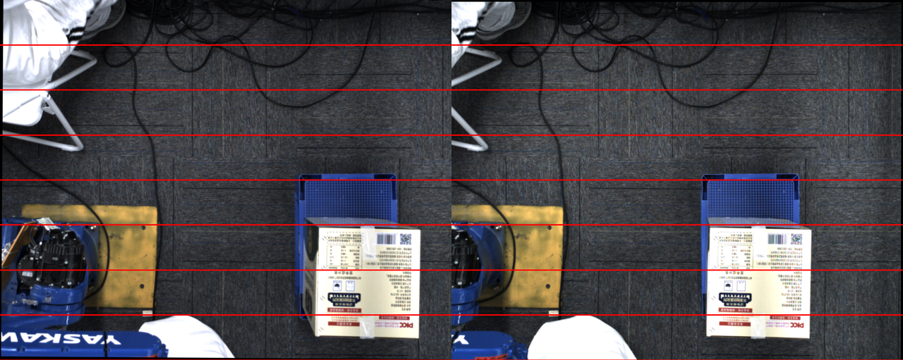 | 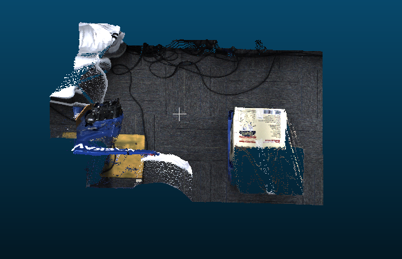 |
1.6 Binocular Camera2D image partial imaging is overexposed
Problem: The "yin and yang face" of the binocular camera causes partial imaging of 2D images to be overexposed
Possible reasons: HDR exposure mode is not turned on, and the light is abnormal
Solution:
- General simple large object scene, such as sacks and cartons
When HDR is turned on, you can see that the partially overexposed areas on the Target surface can show texture, and Point Cloud is improved.
Target’s yin and yang face with complex shapes, such as cylinders and specific shapes
Currently binocular imaging cannot be solved, such as the following Scene
1.7 high-score binocular photography cycle time optimization
Problem: When using binocular high-scoring Camera, the cycle time for a single photo is too long (a single photo is nearly more than 8~10s)
Possible reasons:
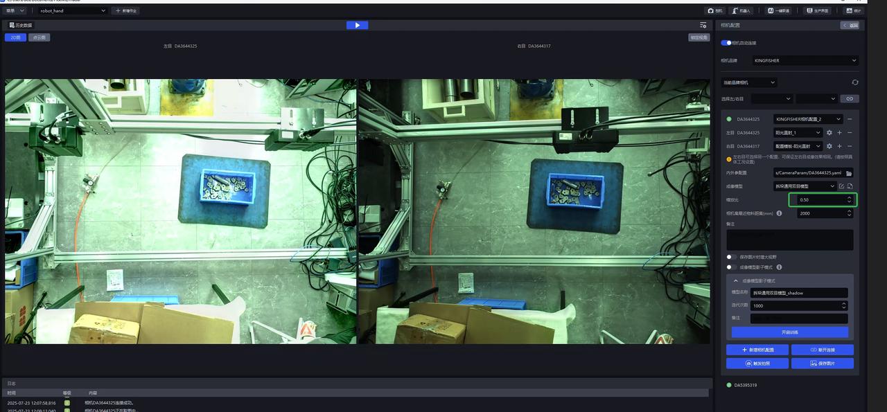
The zoom ratio is 1.0. The image is too large for the high-resolution camera.
High dynamics is turned on, which is equivalent to triggering multiple image captures.
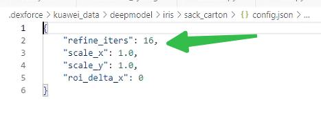
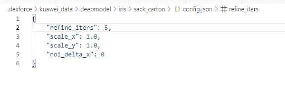
The model Inference uses the default number of 16 iterations, which takes too long for high-resolution images.
Solution:
- Check whether the zoom ratio setting of the camera interface uses 0.5
- Check whether high dynamics is turned off
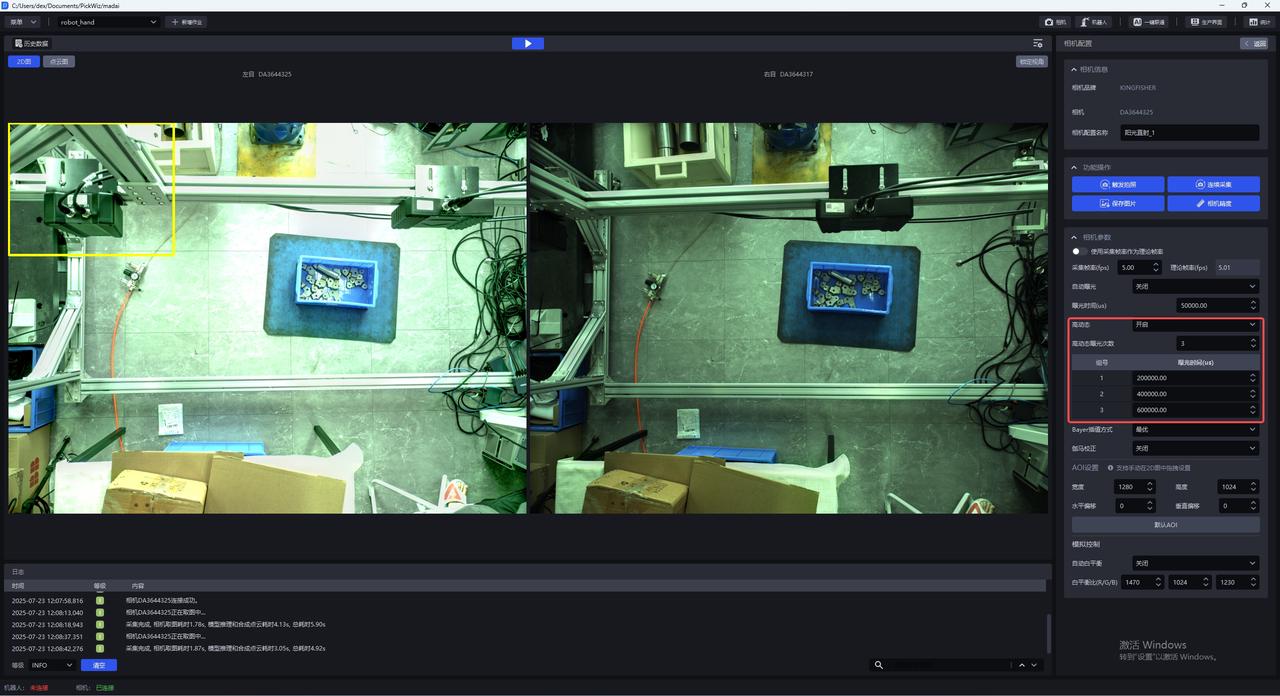
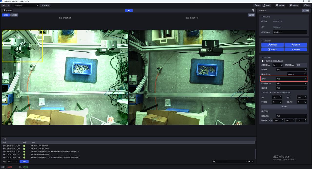
- By modifying the "refine_iters" field in the
C:\Users\dex\.dexforce\kuawei_data\deepmodel\iris\sack_carton\config.jsonfile from 16 to 5, restart the software after the change.
- Note that the Point Cloud effect may deteriorate at this time. You can use the binocular shadow mode in the product to adapt (requires >=1.7.6).
1.8 Black lines appear when taking pictures with binocular camera
Problem: Black lines appear when taking pictures with the binocular camera, as shown in the picture below.
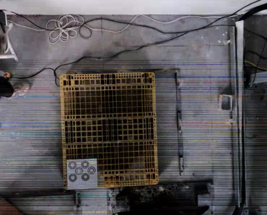

Possible reasons: The network speed is unstable due to the customer replacing a longer network cable, and network problems cause black lines in the KINGFISHER binocular camera image capture
Solution: Prioritize checking the network condition or network cable status on site.
2. Mask Mode & Shadow Mode
2.1 The difference between mask mode and shadow mode
Question: What is the difference between Mask Mode and Shadow Mode, and what Scenes are they applicable to?
answer:
Mask mode: refers to data quickly constructed based on texture + synthetic data, which is directly used for training. The detection capability is equivalent to the Scene corresponding to a given texture (if multiple textures are given, it can detect boxes or sacks with multiple textures), and is generally directly used in situations where actual material detection fails (for example, the detection effect encountered by Yushi recently was too poor); versions after 132 are supported. The training duration is expected to be within 1 hour on an industrial computer.
Shadow mode: refers to the real data accumulated after the model runs the actual Scene and is reused for training. Generally, using Scene has achieved a detection success rate of 95%+ or more, and it is expected to reach 99.9%. Versions after 130 are supported. The training time is expected to be within 1 hour on an industrial computer (the amount of startup data is more than 100 copies).
2.2 Mask mode texture data saving path
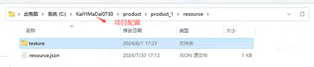
Question: Where is the texture data saved after training in Persona mode?
**Answer:**In the corresponding project configuration folder
2.3 Training new Target in Mask mode
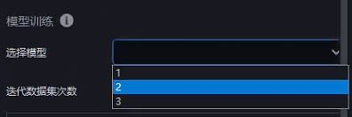
Question: I got model A after training in Persona mode, and a different box was added to the field. Can I continue to use Persona mode for training on the basis of A?
Answer: Yes, you just need to replace the model used in Persona mode training with the corresponding model and enter the new texture
2.4 Mask mode training has no effect
Question: After using Mask Mode, the effect does not change. What is the reason?
Possible reasons: The workpiece model is not updated and the frame texture is incomplete.
Solution:
2.5 Mask mode training failed
Problem: Persona mode training failed
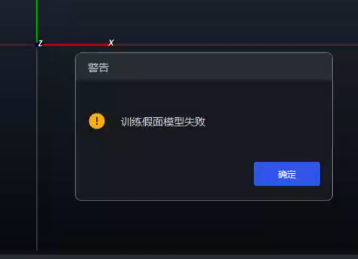
Possible reasons:
Solution:
The folder may not be created successfully due to a code bug.
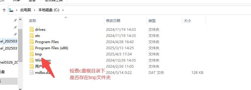
If not, create it and run Mask Mode or Shadow Mode again.
File corruption may occur due to direct power outage or direct restart.
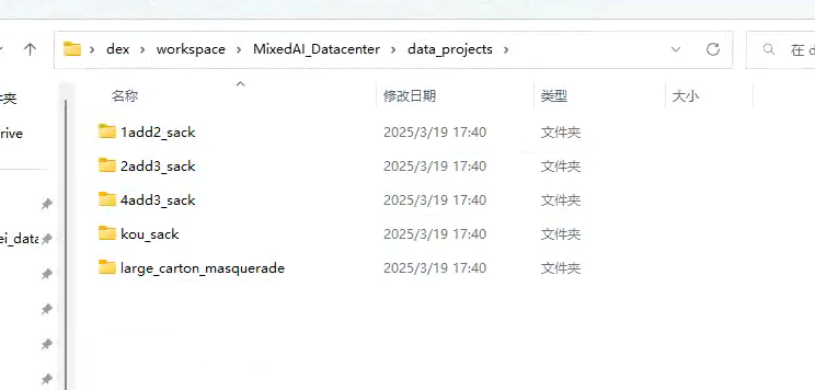
- Pay attention to the five folders under this path, each folder contains info.yaml. If you click info.yaml and find that the files are damaged and cannot be opened normally. Jump to step 2
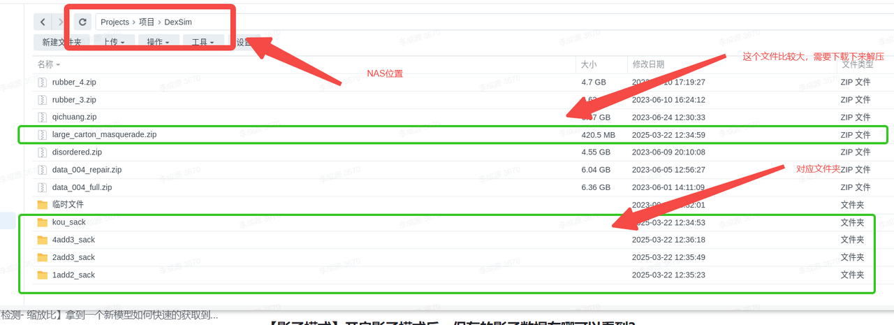
- Find the corresponding folder in the location of the picture above and below on the NAS (note that there is a folder that needs to be decompressed), and after decompression, replace the folder with the same name of the data projects in the picture above. (First delete the folder in data projects and then update it)
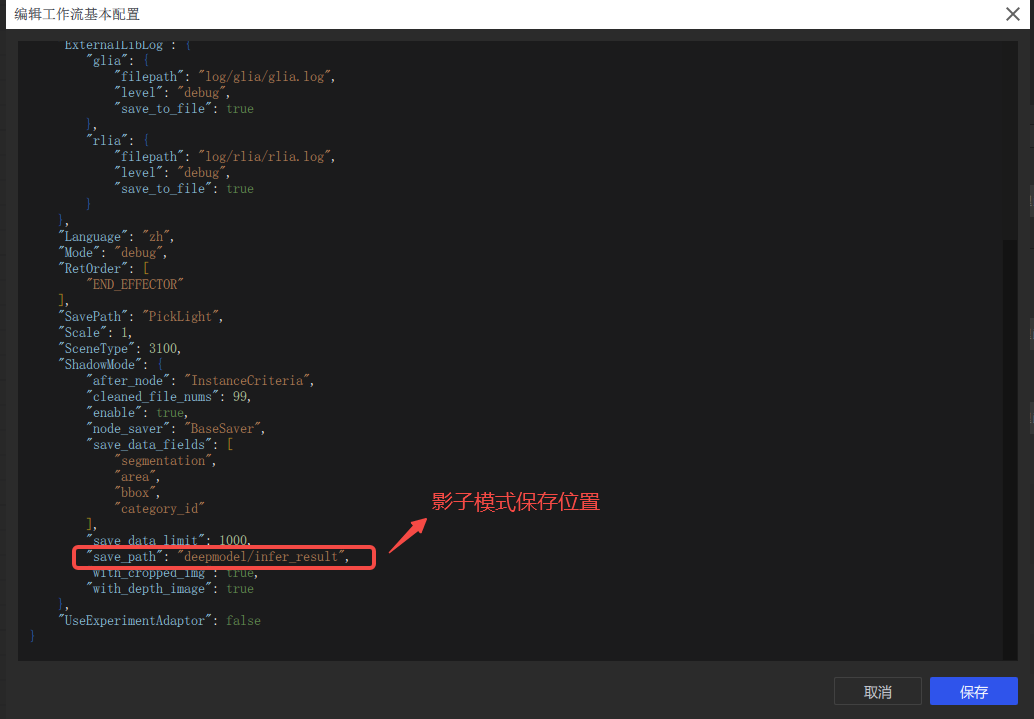
2.6 shadow data saving path
Question: After turning on shadow mode, where can I see the saved shadow data?
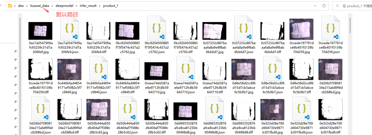
**Answer: **The default is under the kuawei_data path, you can also modify the save path (it is recommended to use the default path)
2.7 Shadow mode training has no effect
Question: After using shadow mode, the effect does not change. Why?
Possible reasons: The model is not updated and the Target type does not match
Solution:
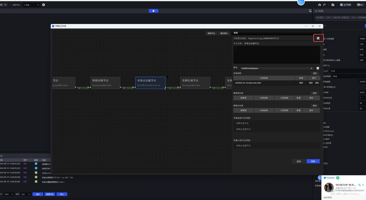
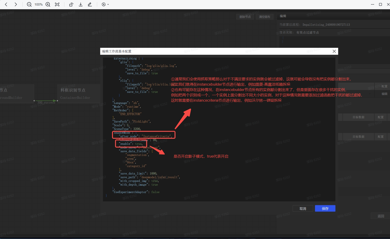
2.8 Shadow mode on position
Question: Where to enable shadow mode for disordered and ordered scenes?
**Answer:**Unordered and ordered Scene are opened by default. If you are not sure, you can follow the path below to view
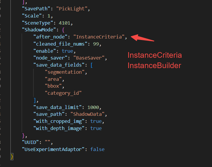
2.9 Shadow mode saves node modifications [1.6.0-1.7.0] Full Scene
Question: How to modify the shadow mode save node?
Answer: Enter the project directory and find the Task configuration based on the TaskID
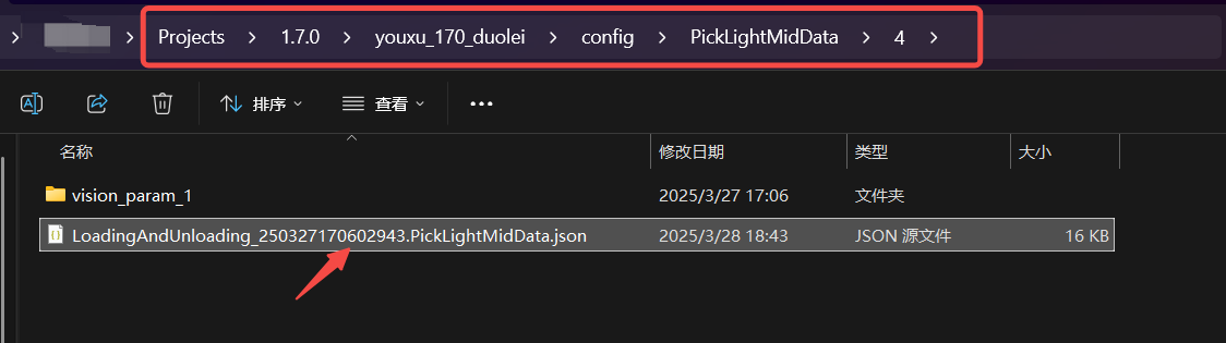
Enter the configuration and modify the contents of the ShadowMode section
3. Destacking Scene
3.1 2D recognition
3.1.1 Quickly obtain the most appropriate zoom ratio
Question: How to quickly obtain the most appropriate zoom ratio
answer:
Use run.py locally for Inference (windows)
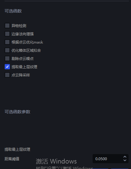
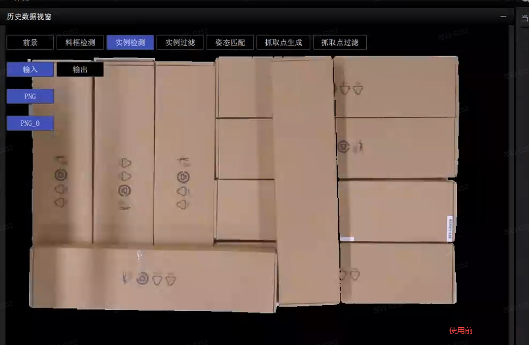
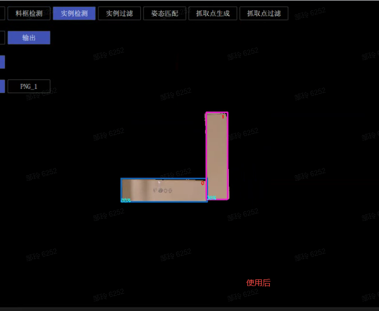
3.1.2 Extract upper texture - individual instances cannot be recognized
Question: Among the cartons of the same size and arranged in an orderly manner, individual cartons cannot be detected. Is there any other method besides optimizing the model?
Possible reasons:
Solution: You can modify the Parameter that extracts the upper texture and keep only the uppermost carton.
3.2 Pick Point processing
3.2.1 pose adjustment
Question: By default, the carton coordinates output by the software are x pointing to the long side and y pointing to the short side. I hope y points to the long side. How to set the Parameter?
**Answer: **It can be set in two situations
RZ angle is not fixed (accepts ±180 rotations)
- Just add a fixed rotation of 90° to the crawling strategy
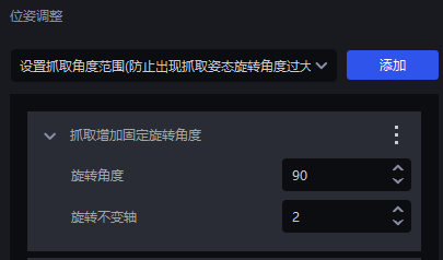
Rz angle fixed
- First add grabbing to increase the fixed rotation angle so that y points to the short side
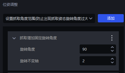
- Secondly, add and set the grabbing angle range (the angle range is set according to the actual situation)
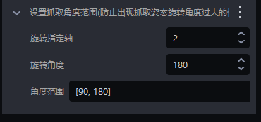
3.3 crawling accuracy
3.3.1 Pick Point is not in the center - Resolution
Question: The carton Instance Segmentation is normal and the mask is complete, but the Pick Point is not in the center. How to adjust it?
Possible reasons: The reason for this problem may be that the crawling calculation-resolution Parameter is relatively large, resulting in a large distance between the calculated masks.
Solution: You can modify the capture-resolution size. The parameter adjustment suggestions are as follows

Adjust parameters
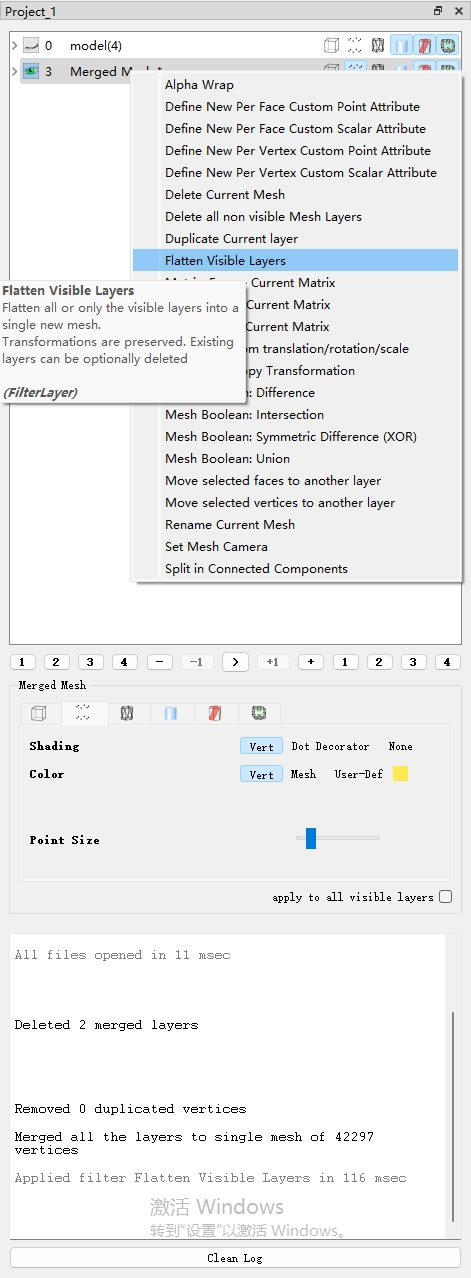
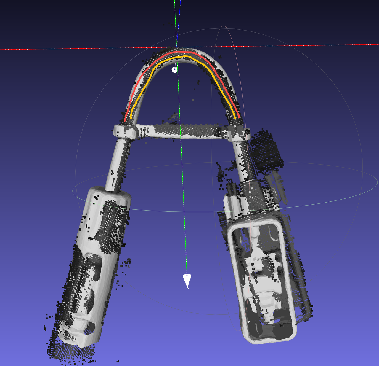
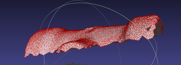
Use Meshlab to open the Point Cloud in the folder where the historical data is located. The file path of the historical data is C:\Users\dex\kuawei_data\PickLight.
Meshlab is a powerful three-dimensional display and operation tool, download address https://www.meshlab.net/#download
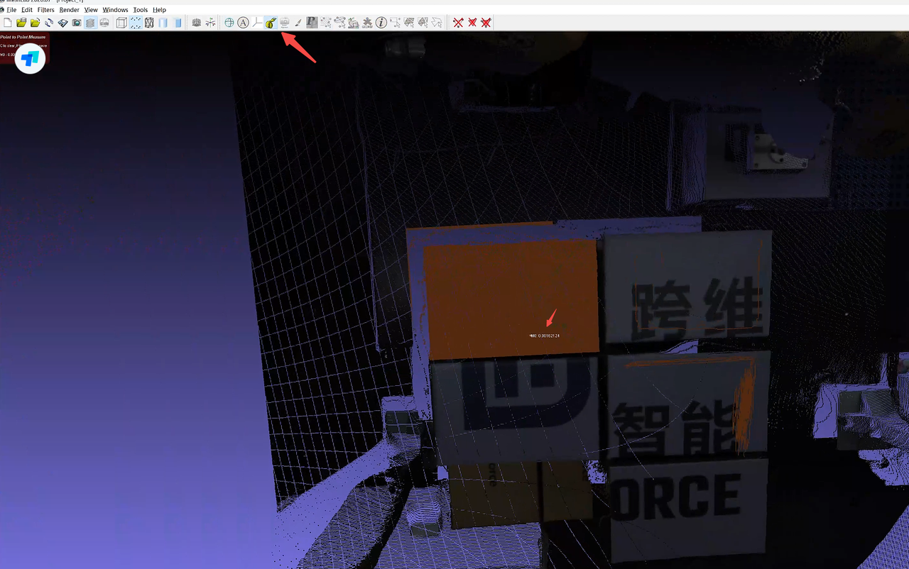
After opening the corresponding Point Cloud in Meshlab, click

Measure the distance between adjacent points and fill in nearby values
In the actual scene, the Point Cloud accuracy of the upper object is smaller, and the Point Cloud accuracy of the lower object is greater, so it is recommended to fill in a slightly larger value.
As shown in the figure below, the measured Point Cloud value is 0.0016, so you can fill in a value near this value such as 0.002 as the Point Cloud accuracy
3.3.2 The grabbing angle is too large
Question: The Instance Segmentation of the sack is normal and the mask is complete, but there is a bulge in the sack that causes the grabbing angle to be too large. How can I make the grabbing angle smaller?
Solution:
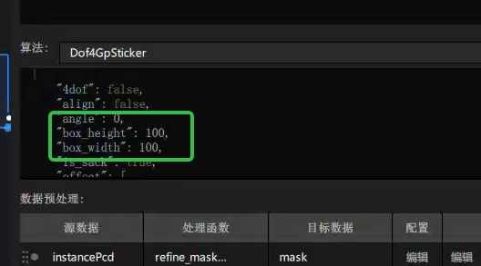
You can adjust the size of the patch by
Enter the visual workflow and add "box_width":100, and "box_height":100, (representing the size of the patch, which can be adjusted according to the actual sack) to the dof4 algorithm
3.3.3 Pick Point is not in the center - split to the side
Problem: The segmentation is correct during detection, but the sides of the sack will also be segmented, resulting in a deviation in the capture that is not in the center.
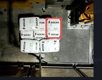
**Possible reason: **The sides are also included in the calculation.
**Solution:**You can grab and calculate from the visual Parameter-Select the coordinate system from 1 (roi coordinate system)->2 (represents the selection of the coordinate system perpendicular to the sack)
3.3.4 Pick Point is not in the center - Pick Point deviation is large
Question: The segmented mask is correct and complete, but the Point Cloud output by the Pick Point generation node is incorrect?
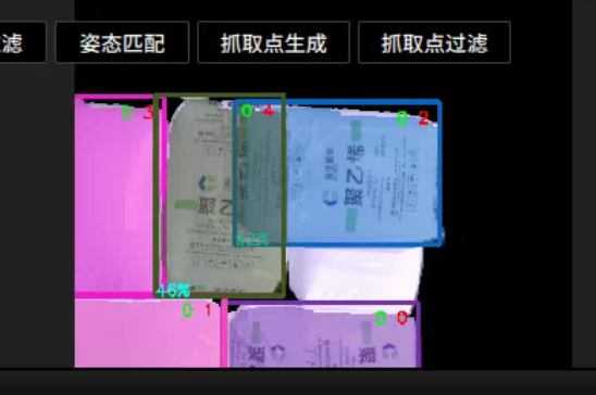
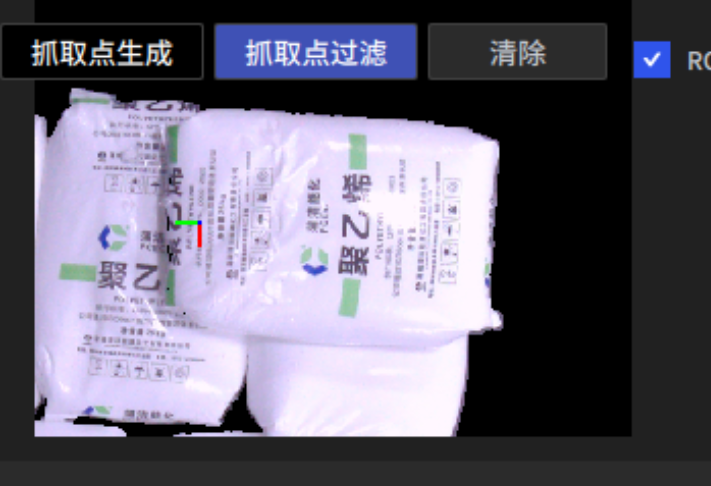
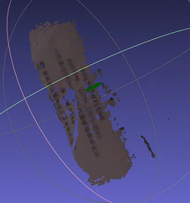
Possible reasons: This situation is generally due to a problem with the Parameter setting in the optional function. For example, the average distance of the Point Cloud elimination function is too small than the Parameter setting, and a large number of points in the sack Point Cloud are eliminated, causing the Pick Point to shift.
**Solution:**Adjust Parameter settings
3.3.5 Pick Point is not in the center - the segmentation is rough
Question: The sack dividing frame is too large, the mask adheres to the lower layer, and the Pick Point is offset. How to solve it?
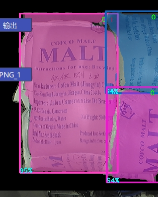
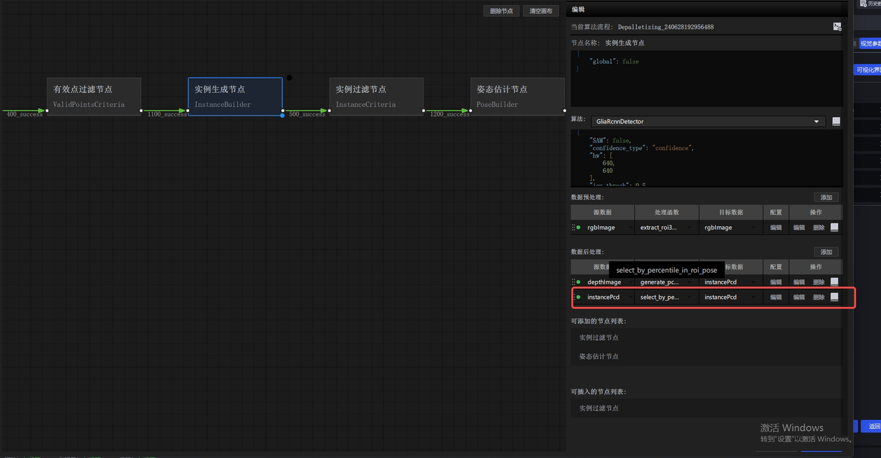
Solution: Because the mask is too large, the ontology Point Cloud adheres to the lower Point Cloud. The lower Point Cloud needs to be removed, leaving only the upper Point Cloud.
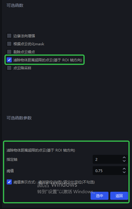
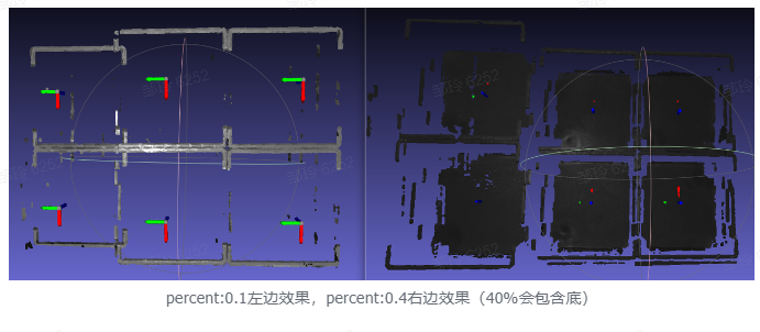
- Check the optional function in the visual parameter to filter out the Point Cloud where the object distance exceeds the limit (based on the roi axis direction) (v1.4.2)
3.3.6 Pick Point is not in the center
Question: Check the segmentation rendering. The segmentation and mask are normal, but the Pick Point is not in the center. How to solve it?
Possible reasons: Too much noise is adhered to the instance
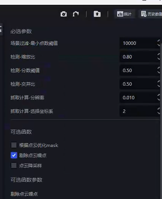
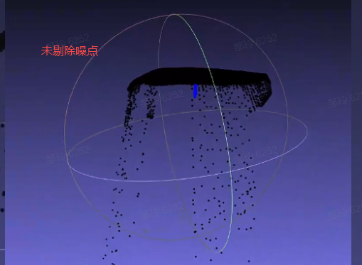
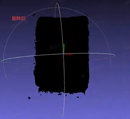
Solution: Check the output of the captured node in the corresponding historical data, and you can check to remove Point Cloud noise.
3.3.7 Pick Point mode: 4-axis/6-axis (≤1.4.1)
Question: When the robot arm has four axes, where is the corresponding coordinate output set?
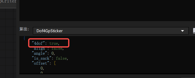
Answer: If the robot arm has four axes, set 4dof in the dof4 algorithm configuration in the grabbing generation node to true; if it has six axes, set it to false (need to enter the visualization workflow)
3.4 optional function
3.4.1 fill_hole Point Cloud generates noise after hole filling.
| Version dependency | Add location | Source data | Target data |
|---|---|---|---|
| PickLight >= 1.5.0 | Post-processing of foreground nodes or pre-processing of instance generation nodes | depthImage | depthImage |
Recommended to use in glia-0.3.3 and above versions
Problem: When entering the visualization workflow and using fille_hole to fill holes, pyramid-like stepped noise appears, such as
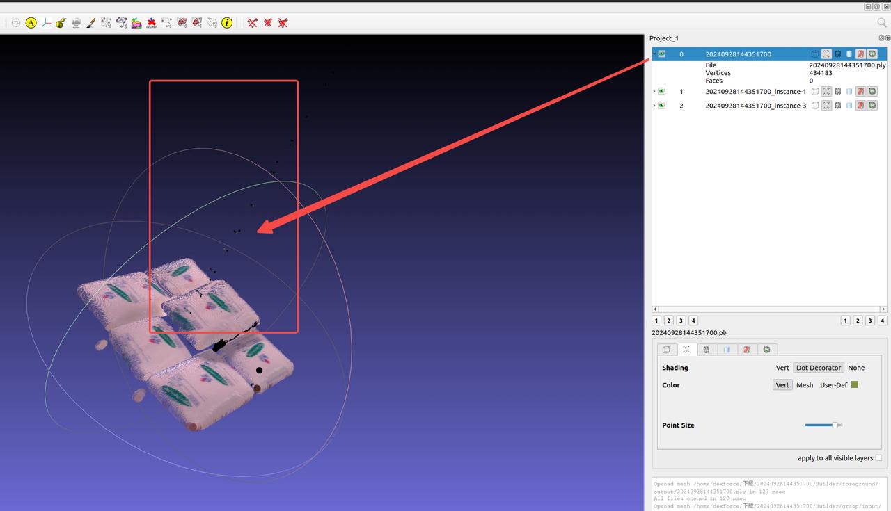
Possible reasons: The area with a depth of 0 in the depth image affects the filling of holes. This is fixed after pickwiz version >=1.5.0.
Solution:
It is recommended to seek support from industry and research institutes to update the on-site software version.
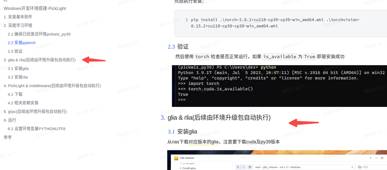
Confirm or upgrade glia>=
Confirm or upgrade pickwiz >= 1.5.0 or upgrade the backend whl package to release-1.4.5.1 (commit version >=xxx, PR to be merged)
After updating, restart the software and run the historical data again.
3.4.2 filter_by_color function usage
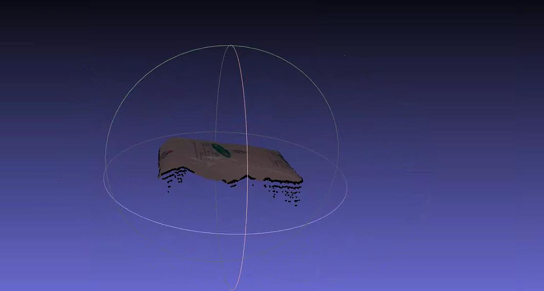
Problem: The instance generates false detection, and the bottom tray or other parts are mistakenly detected
Solution: When there is a false detection in instance generation, and the bottom tray or other location is mistakenly detected as a target to be grabbed, first observe the difference between such detected instances and normal targets.

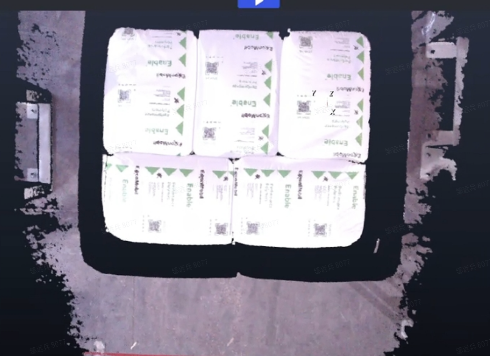
For the scene in the picture above where there is a big difference between the sack and the pallet, enter the visual workflow and add the function filter_by_color to filter according to the specified upper and lower color limits.
- Add filter_by_color to the instance filter node
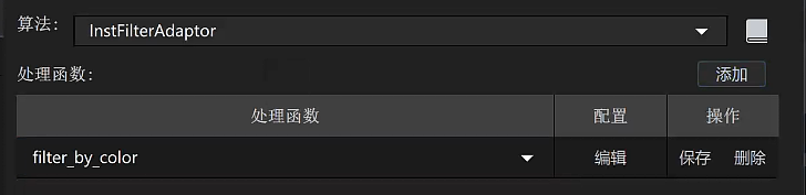
- Parameter description
| Parameter | setting value | Description |
|---|---|---|
| min_c | 0.1 | The minimum value of color filtering, 0 is black, 1 is white |
| max_c | 2 | The maximum value of color filtering, which cannot be less than min_c |
| threshold | 0.7 | Filtering Threshold. When the ratio of the number in the filtering range (min_c, max_c) to the mask area in the instance mask is lower than the Threshold, the instance is filtered |
| inverse | false | Whether it is inverted. If it is true, the points in the mask whose color is less than min_c or greater than max_c will be used to calculate Threshold |
According to the above Parameter settings, the black pallet instances can be filtered out, and only the sack instances will be retained.
3.4.3 is_top_safety Is there any other obstruction above the Pick Point?
Question: How to judge whether some objects to be grabbed in the Scene are safe and unobstructed
Answer: You can add the is_top_safety function to the instance filter node
- Parameter description
| Parameter | Default value | Description |
|---|---|---|
| x_length | 1.0 | Parameter necessary for cuboid generation, used to determine whether there are obstructions within the length range of the Pick Point along the attitude x direction |
| y_width | 1.0 | Parameter necessary for cuboid generation, used to determine whether there are obstructions within the width range of the Pick Point along the posture y direction |
| z_depth | 2.0 | Parameter necessary for cuboid generation, used to determine whether there are obstructions within the width range of the Pick Point along the attitude z direction |
| bindwidth | 0.1 | The distance Threshold in the direction of |
| num_threshold | 1000 | If the occlusion point exceeds the Threshold, the Pick Point is considered to be occluded |
| debug | false | Whether to save Point Cloud data to observe whether the cuboid generation is reasonable |
| save_path | "" | data saving path, note that the path under win is separated by \\ |
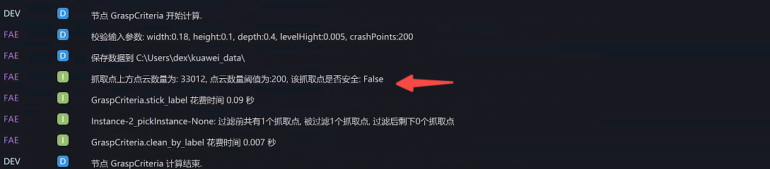
3.4.4 is_safety Whether the fixture where the Pick Point is located collides
**Question:**What is the function of is_safety?
Answer: Used to filter possible collision Pick Points, suitable for situations where the robot arm picks up objects and the fixture model is known
- Parameter description
| Parameter | Default value | Description |
|---|---|---|
| prewin | 100 | The unit is pixels. A mask is generated within the specified pixel range around the Pick Point for subsequent collision judgment. If this value is too large, it may increase time consumption and cause calculation exceptions. It is recommended to set it slightly larger than the long-side pixel length of the Target mask itself. You can evaluate it by viewing the data in debug_vis. |
| threshold | 1.0 | Threshold to judge whether the grabbing posture is safe. If the number of Point Clouds in the fixture exceeds the Threshold, it is judged to be unsafe |
| roi_crop | true | Whether to crop the Point Cloud and keep only the Point Cloud within the roi3d range |
| debug_vis | "" | debugging data storage path, save the information during the debugging process to the specified path mask.png: The mask range generated according to prewinParameter Cloud |
| use_projected_mask | false | Whether to use model projection. If it is false, the mask passed in by the instance generation node is only turned on when the target to be captured has an accurate model. |
- Use effect log
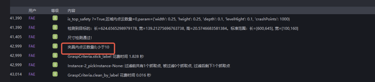
4. Loading and unloading Scene (ordered/unordered)
4.1 deep learning model
4.1.1 model recognition is incomplete
Problem: The model recognition is incomplete, and the number of Inferences for multiple pictures has a maximum limit (usually 20)
Possible reasons: When exporting the model, the maximum identifiable number is set to (20)
Solution: Contact the model provider to re-export the model
4.1.2 model detection key points are abnormal.
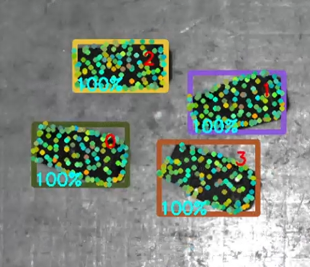
Problem: Abnormality occurs in key points of model detection
Possible reasons: The reason for this problem is that when we use one-click connection for model training, the key points are obtained by downsampling ourselves. When we get the trained model, new key points will be generated.
Solution: Key points need to be replaced with new ones.
4.1.3 Dual/Multiple Template Production Method
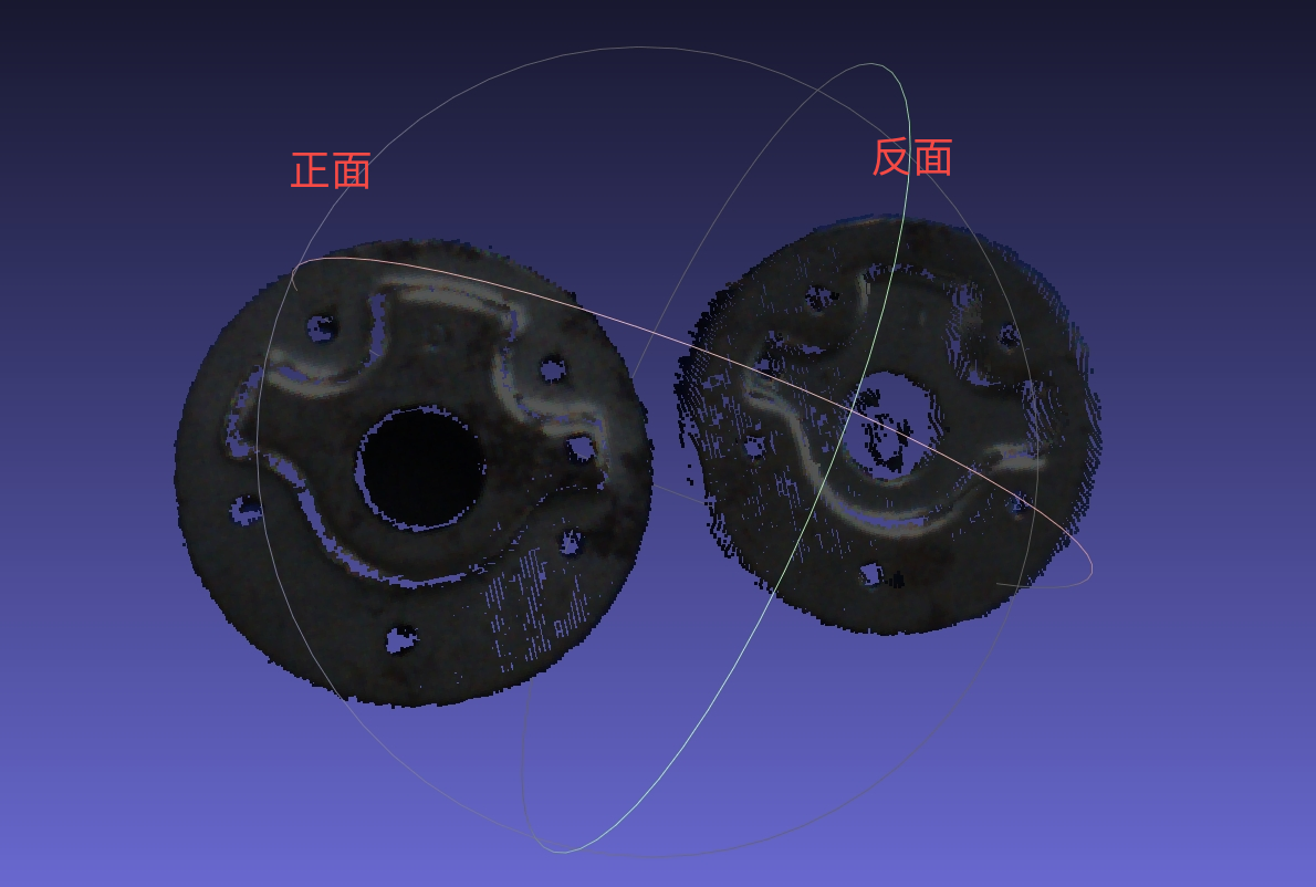
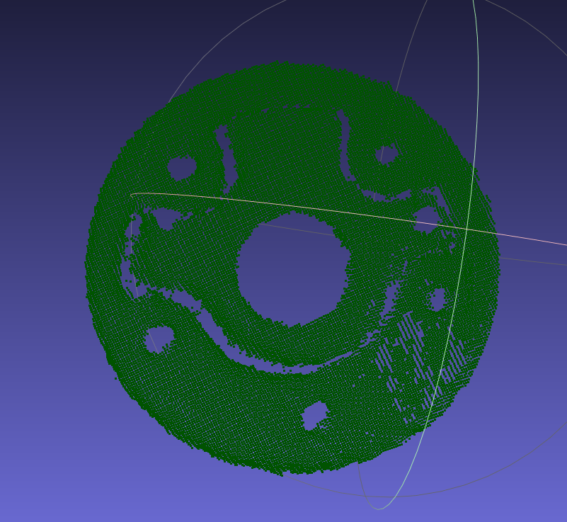
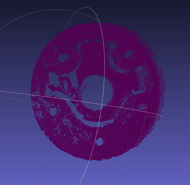
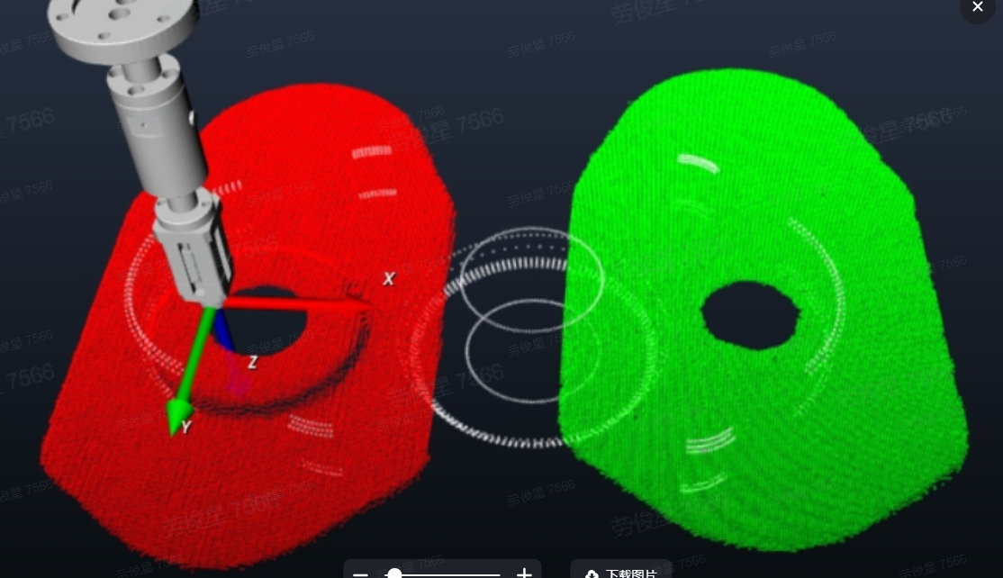
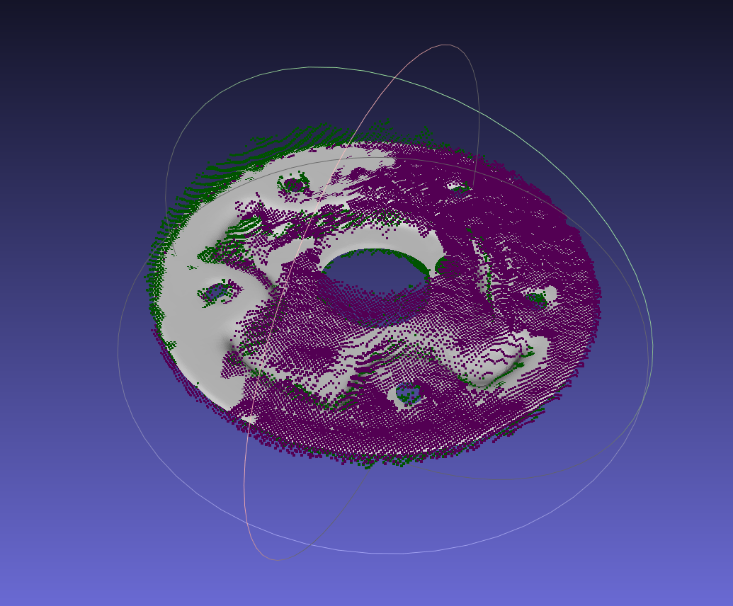
Use Camera to capture the PCD (Point Cloud Data) of the front and back of the Target, color them separately, and after aligning with the model CAD, splice the colored PCD (Point Cloud Data) of the front and back together as the template PCD (Point Cloud Data); color the key PCD (Point Cloud Data) point by point to make the two colors evenly spaced;
Operating steps:
|
|
|---|---|
|
 |
|    |
|  |
| |
| Something like this: 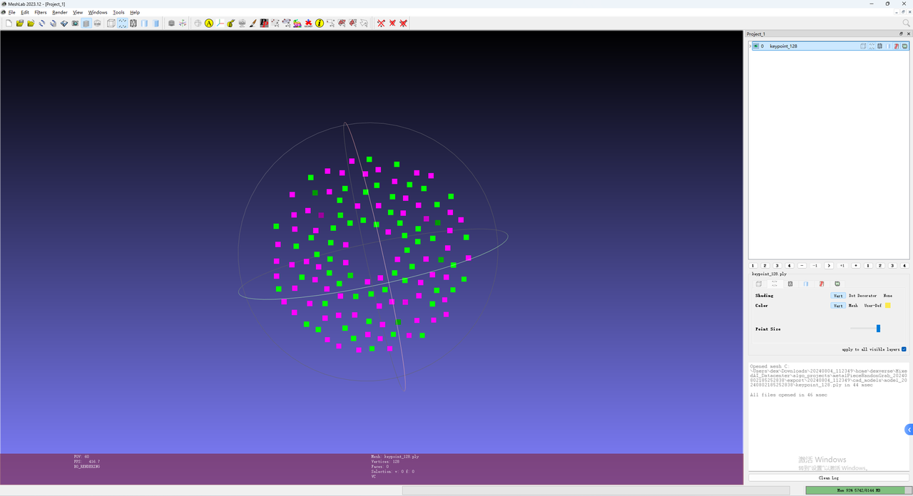 |
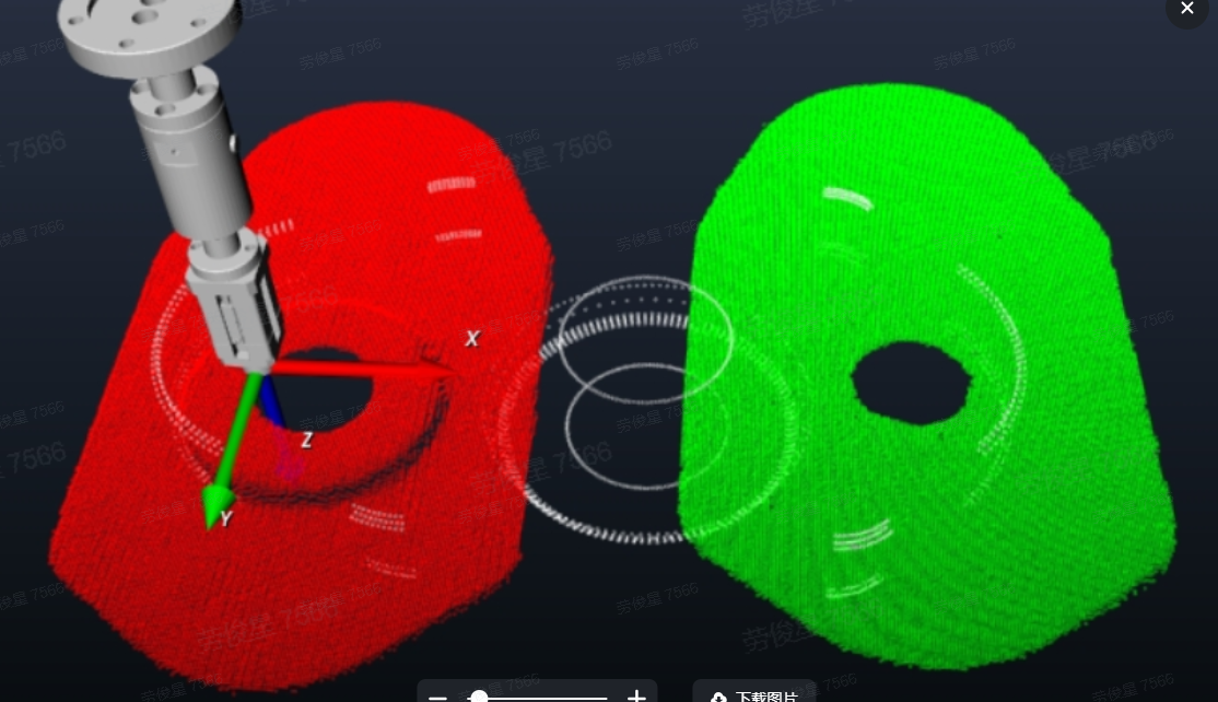
4.1.4 How to make and use double templates with the same shape and flat target using SpitialRansc registration
Got three documents
Keypoint ply file (keypoint_128.ply)
Point Cloud model files for the front and back sides. Generally extracted from ScenePoint Cloud, positive templates are colored green and negative templates are colored red. (point_front.ply, point_back.ply)
Grid model (model.ply)
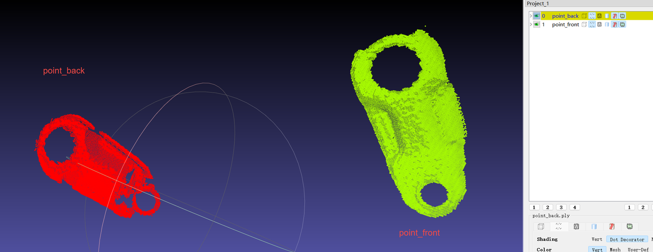
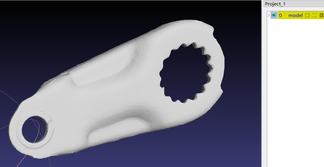
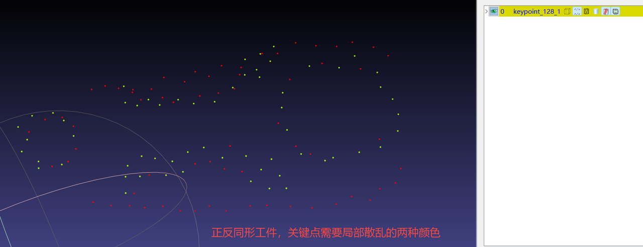
[If it is a three-dimensional piece, the key points are layered in two colors, and the Point Cloud template only uses the Point Cloud visible to the Camera]
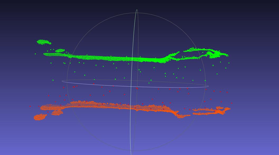
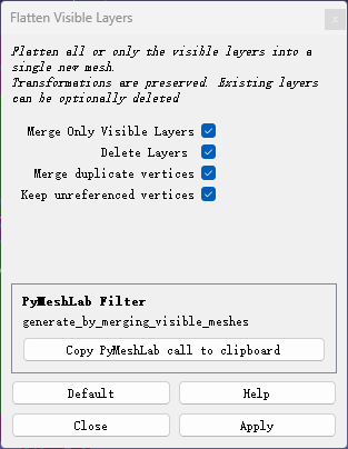
- After the two Point Cloud templates are aligned in CAD, Point Cloud splicing is performed to generate a dual-template Point Cloudply file. [After PCD (Point Cloud Data) aligns CAD, each template is saved separately to avoid realignment when the template needs to be adjusted later]
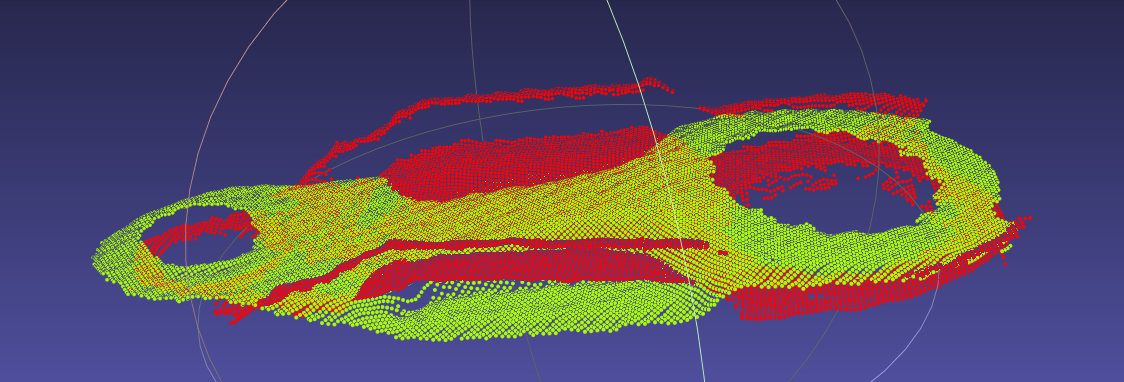
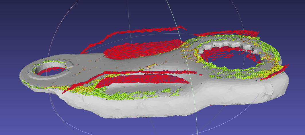
Import the three files into pickwiz
[Note]: Check whether the Point Cloud double templates are aligned and colored, check whether the key points are partially scattered in double colors, and the double colors of the template and key points must match.
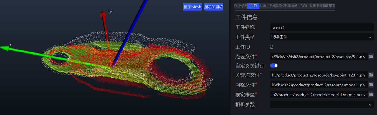
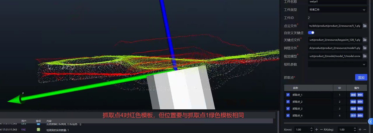
Pick Point production
[Note]: Pick Points are made in sequence. Please read clearly the requirements for making each Pick Point.
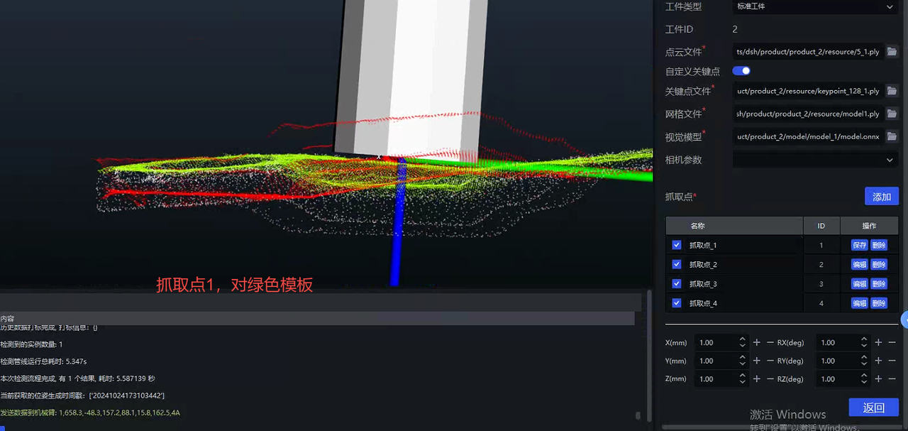
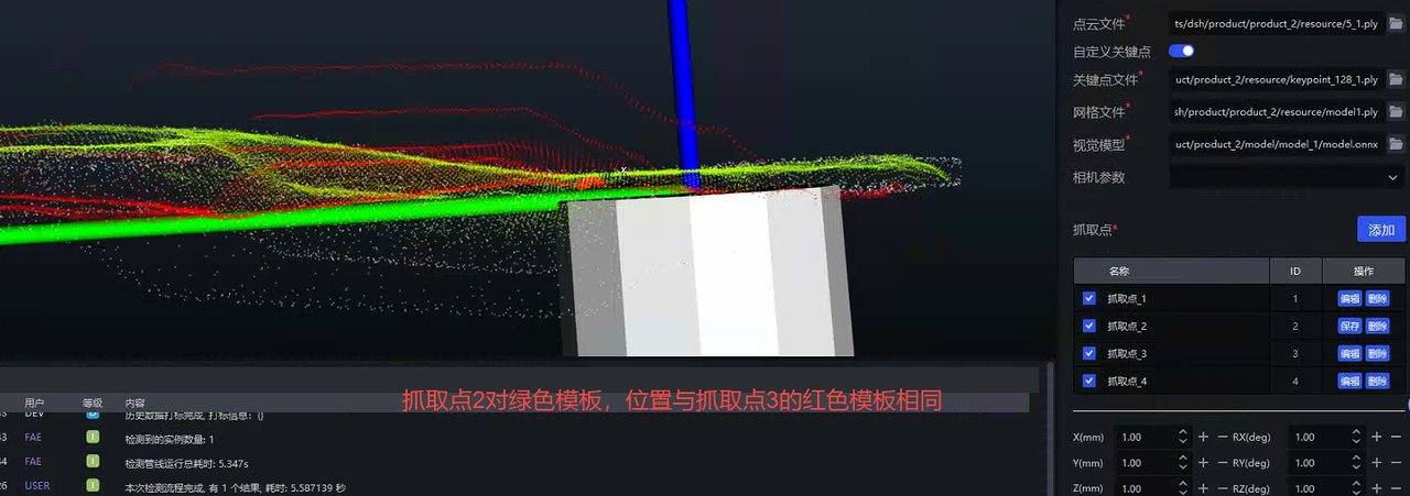
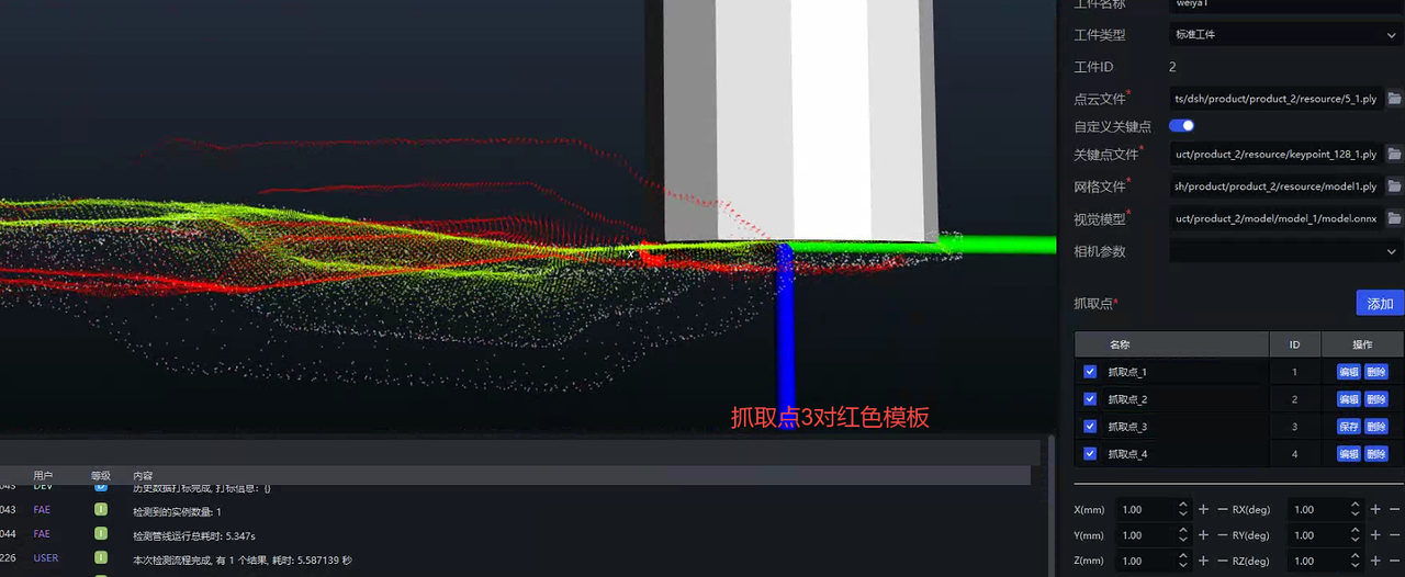
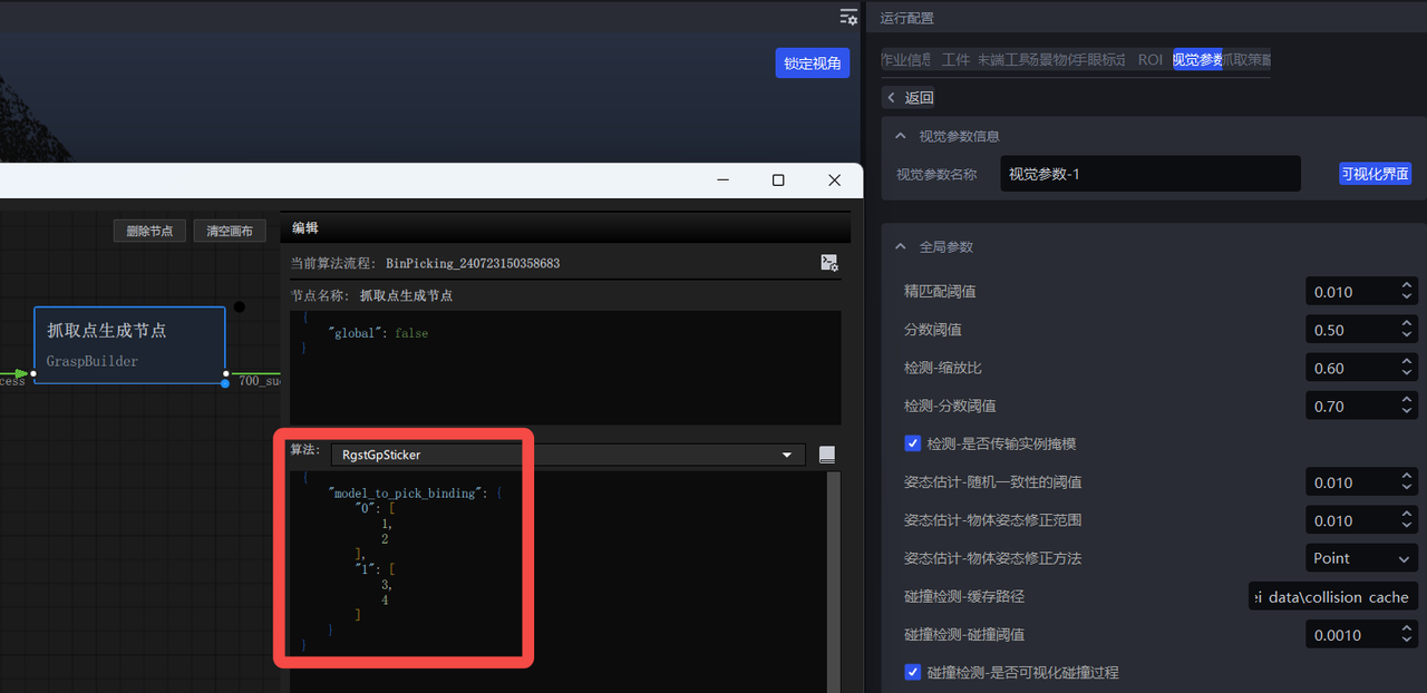
- Open the visual interface and add dual template binding information
{
    "model_to_pick_binding": {
        "0": [
            1,
            2
        ],
        "1": [
            3,
            4
        ]
    }
}
- Added option "Pick Point Serial Number" in Robot settings
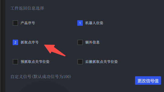
- Click Run, and there are 4 Pick Point numbers returned (1, 2, 3, 4). If the accuracy is high, you need to use a script to teach 4 Pick Points.
4.1.5 Auto-enhanced usage improves predictions through data augmentation
Please see the detailed introduction [General Target Visual Parameter Adjustment Guide] (../视觉参数/通用工件视觉参数调整指南.md)
4.1.6 data rendering CAD model correctness
The current way to obtain CAD models:
The customer directly provides the original CAD
Scan based on actual Target
Either way, make sure the CAD model is correct (size, orientation, type, etc.)
Counterexample 1: The scanned Target and the actual TargetPoint Cloud are inconsistent (the opening angle is inconsistent)
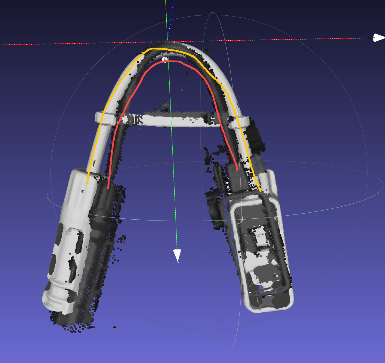
4.1.7 TRT model export
When exporting onnx model, add use-trt option
python -m mixedai.scripts.export \
        --config-file config_path \
        --model-file model_path \
        --sample-image image_path \
        --use-trt
Use glia to export trt model
The following operations are all in the environment of pickwiz_py39, conda activate pickwiz_py39
- rcnn
python -m glia.dl.utils.trt_converter \ --onnx onnx file path, such as xxx.onnx \ --image image file path, for example xxx.png \ --model-type rcnn \ --saveEngine xxx.trt \- yolo
python -m glia.dl.utils.trt_converter \ --onnx onnx file path, such as xxx.onnx \ --model-type yolo \ --saveEngine xxx.trt \- Binocular
python -m glia.dl.utils.trt_converter \
        --onnx onnx file path \
        --model-type stereo \
        --saveEngine xxx.trt \
        --optShapes=image1:1x3x480x640,image2:1x3x480x640 \
        --fp32 \
        --workspace=6000 \
        --tacticSources=-CUDNN,+CUBLAS \
        –-builderOptimizationLevel=3
For more detailed export instructions, please see: http://doc.open3dv.site/glia/doc/master/text/application/trt_converter.html
- Use the gliaInferenceonnx model and the trt model to see if the results are consistent
python -m glia.dl.utils.inference --image-file "./*.png" \
        --model-file .trt .engine or .onnx model \
        --output-dir ./ \
        --bbox-mode aabb (or obb)\
            --scale 1.0
4.1.8 extract_roi3d_rgb settings
Remove the corresponding images outside the ROI3D area to achieve the purpose of background removal
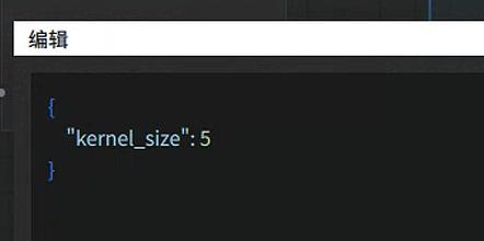
Parameter: Fill core size Before 1.5.1: kernel_size
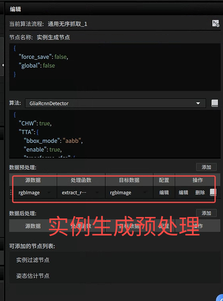
After1.5.1:
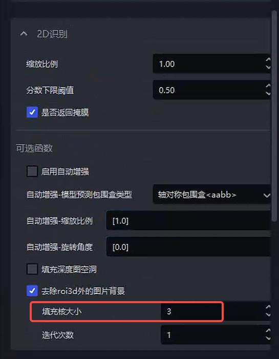
*******Notice*******Due to the lack of Point Cloud in the area to be detected, holes appear in the picture after removing the background, which affects the detection effect. At this time, it is necessary to increase the size of the filling kernel to fill the holes. The specific effect is as follows
| kernel_size | Original image | Detection effect |
|---|---|---|
| 5 | 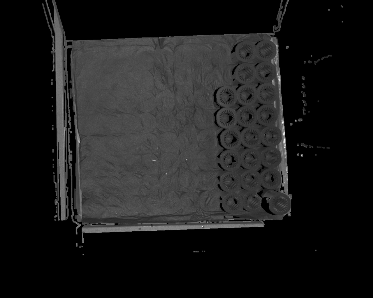 The default configuration is 5. If the Point Cloud in the area to be detected is missing, there may be many holes in the area, which will affect the detection results The default configuration is 5. If the Point Cloud in the area to be detected is missing, there may be many holes in the area, which will affect the detection results | 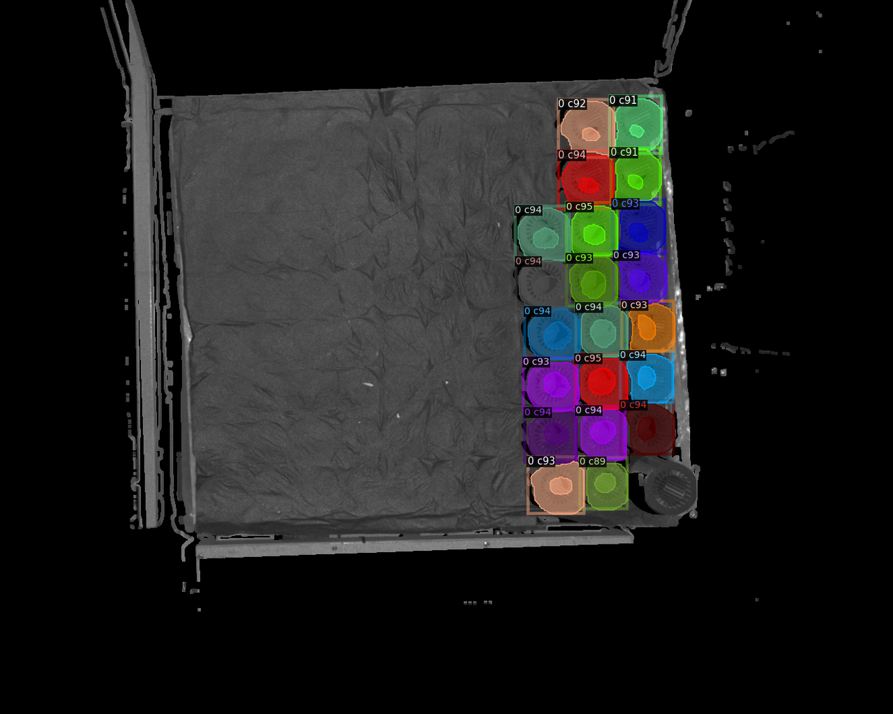 |
| 7 | 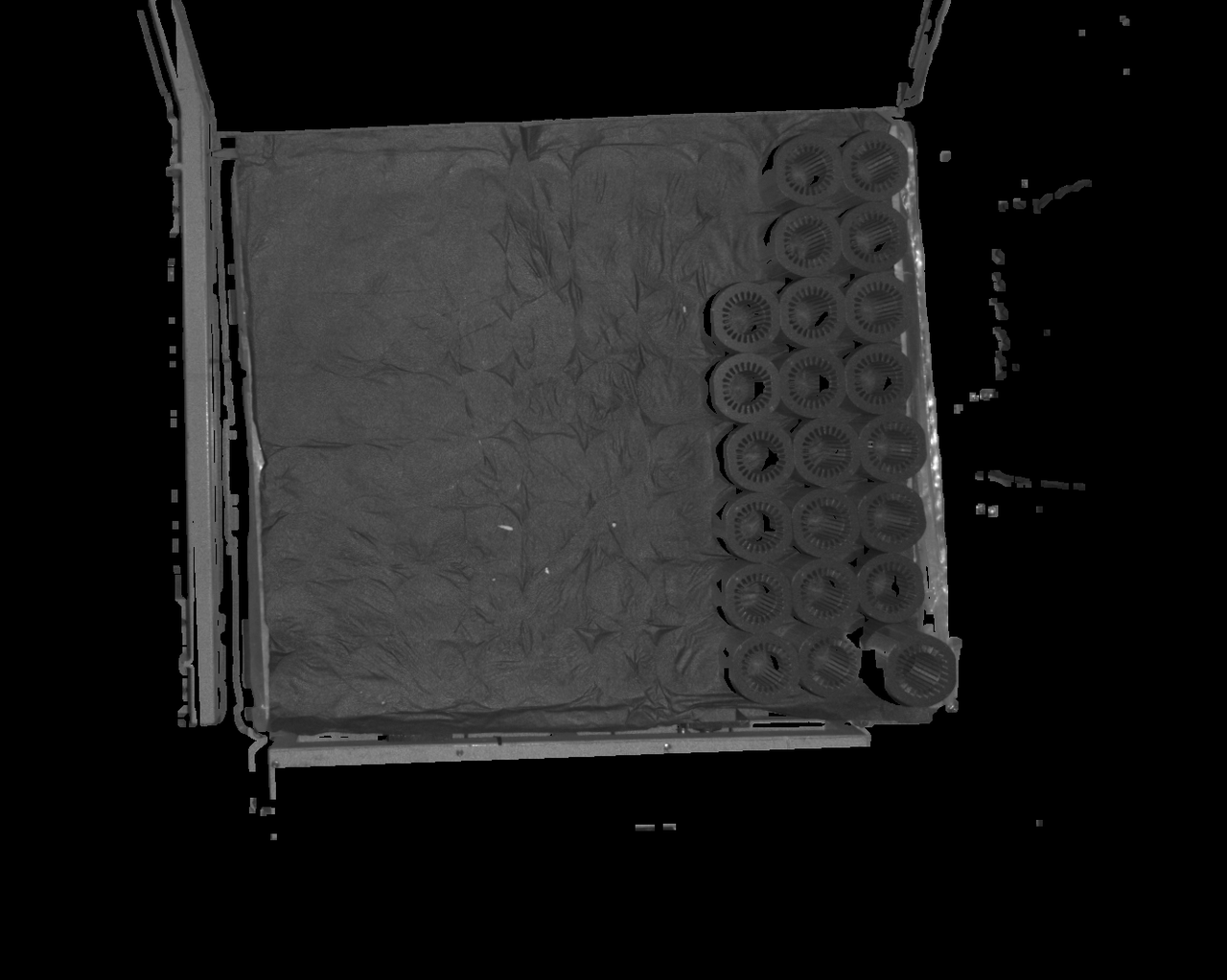 | 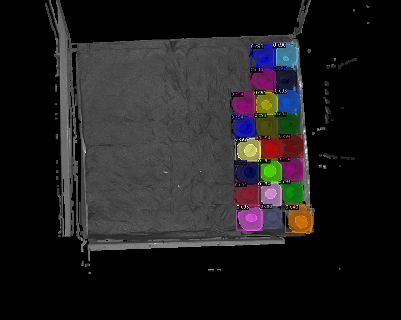 |
| 9 | 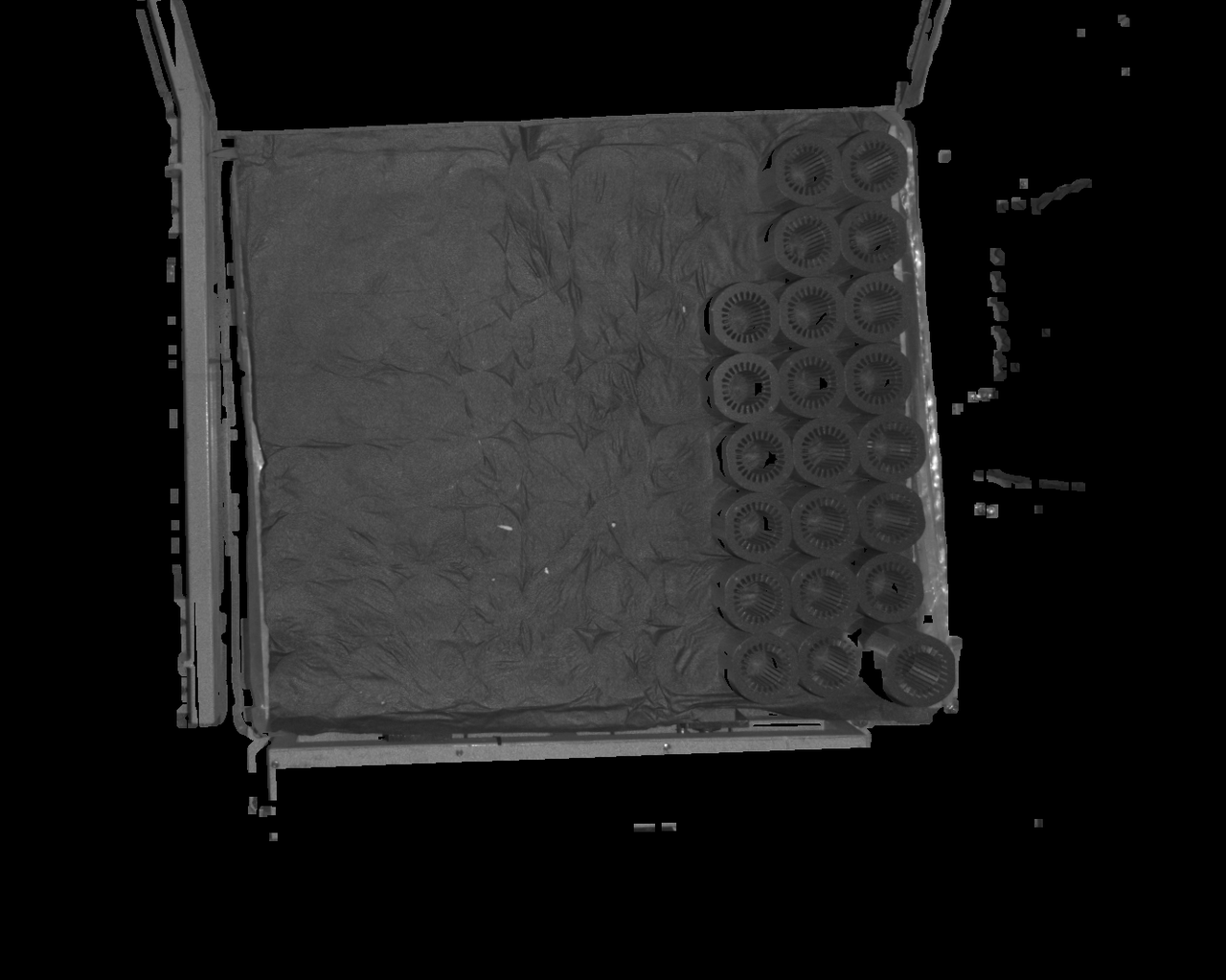 | 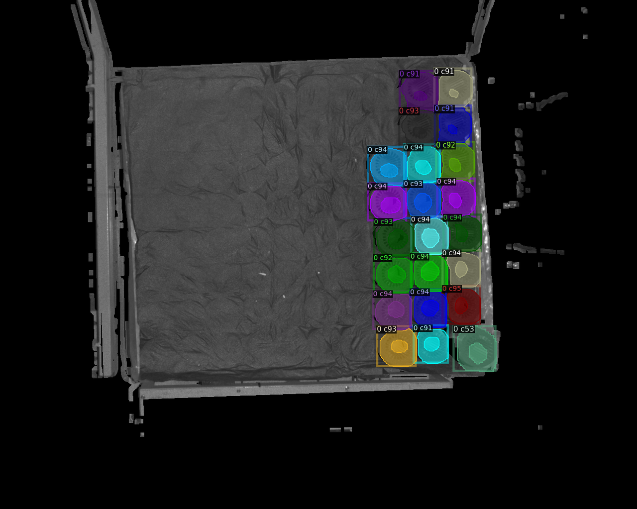 |
| 11 | 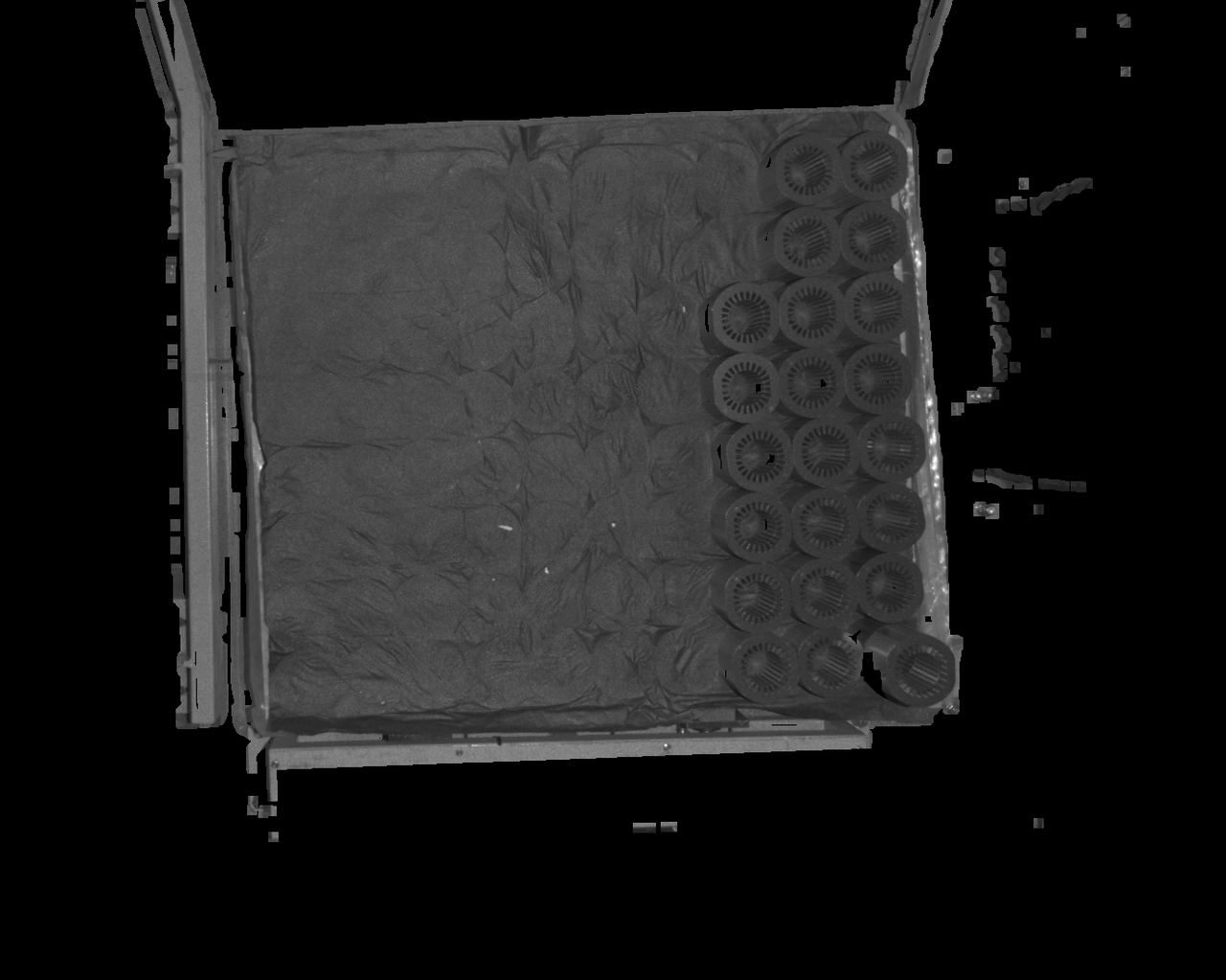 | 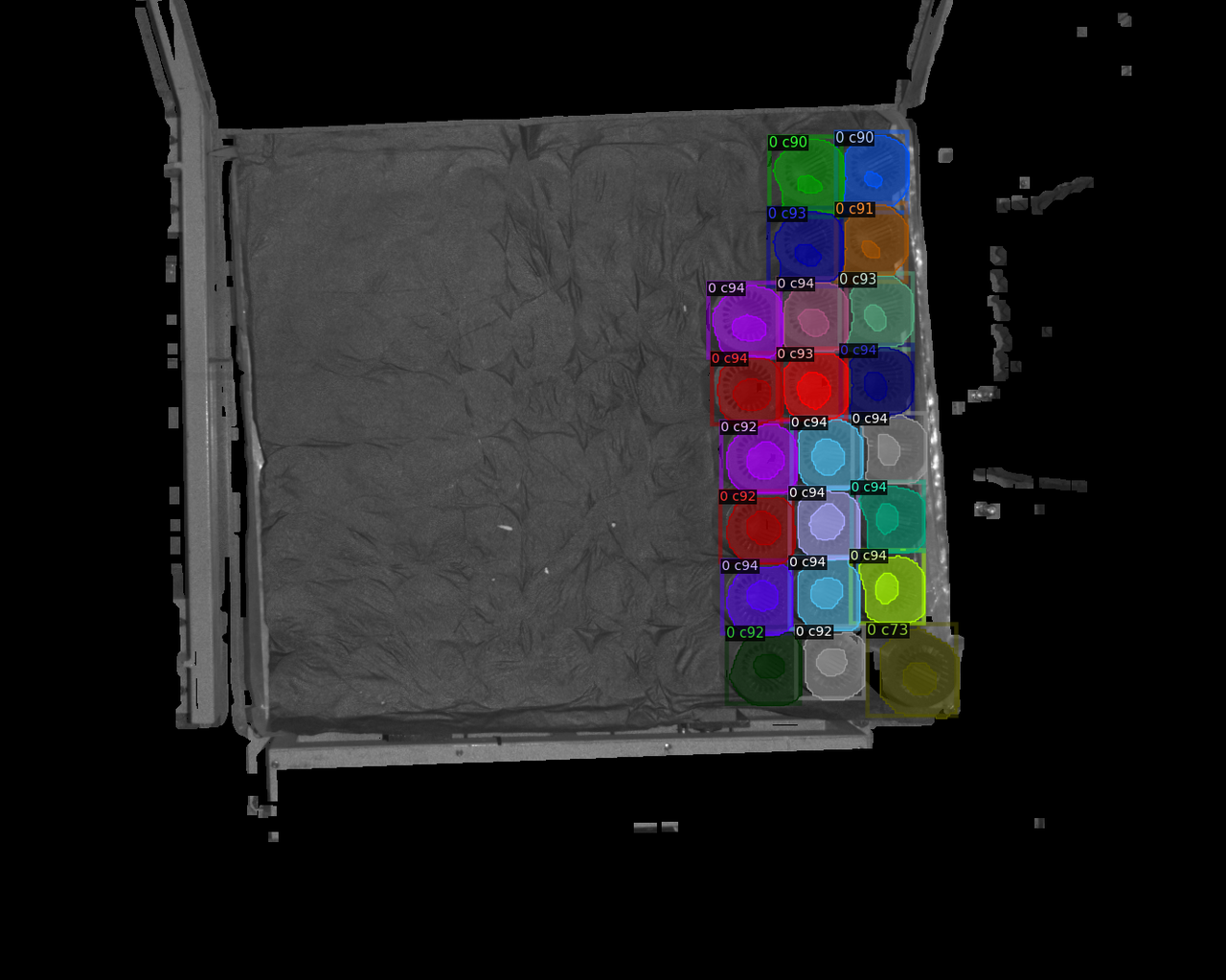 |
| 13 | 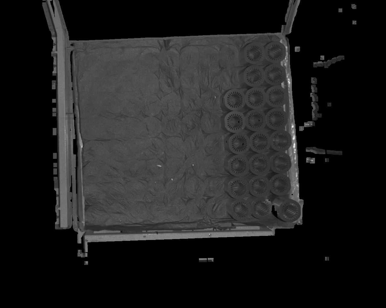 | 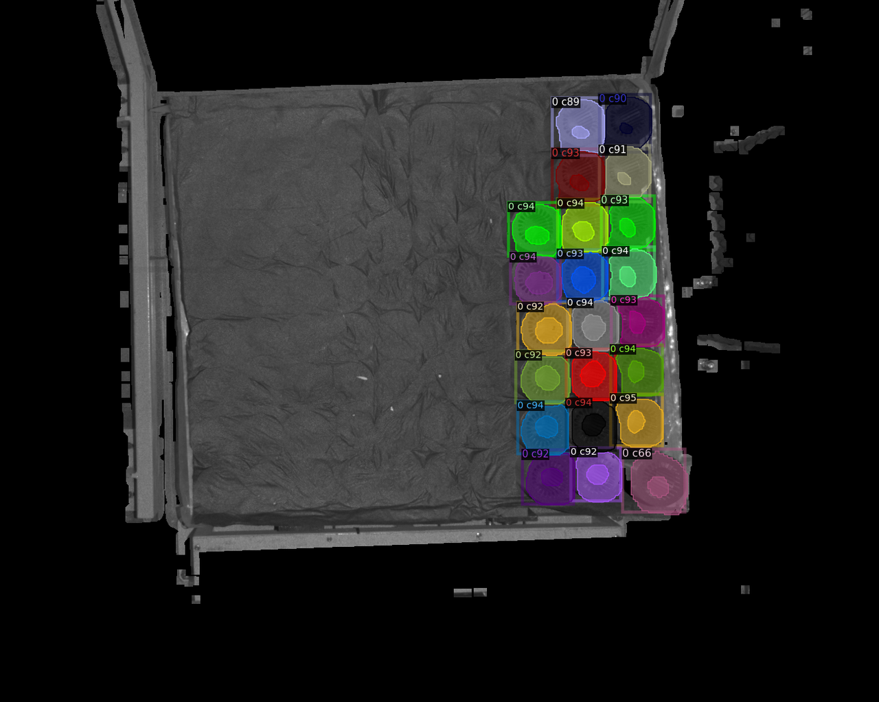 |
| 15 | 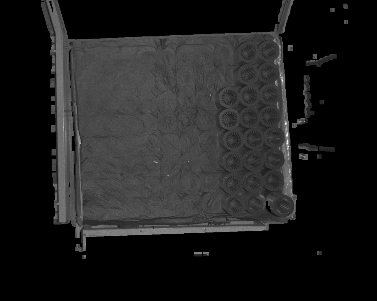 | 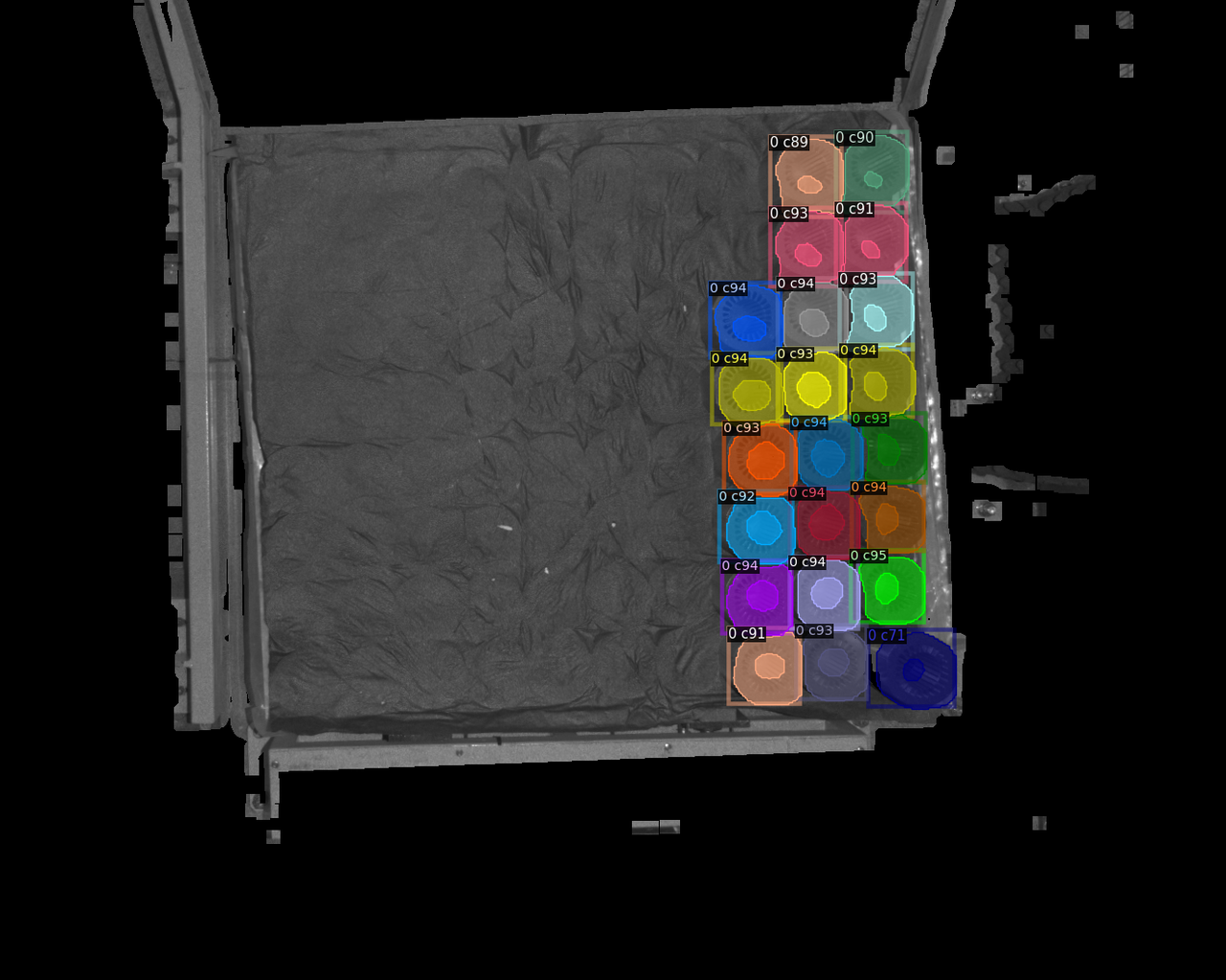 |
| 17 | 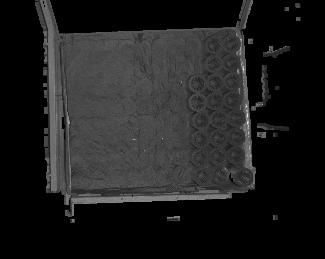 | 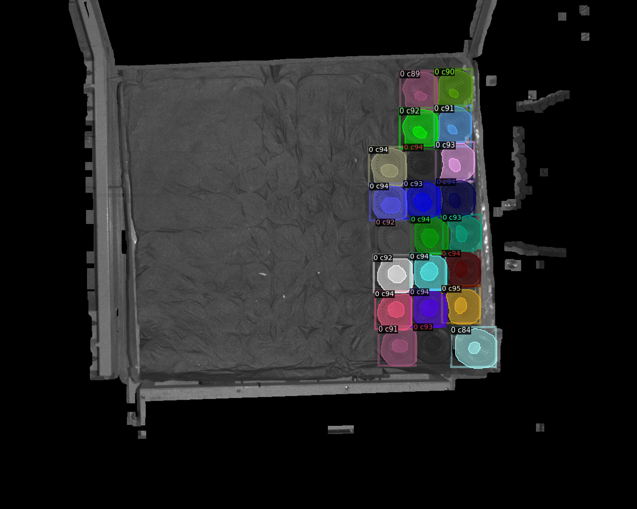 |
| 19 | 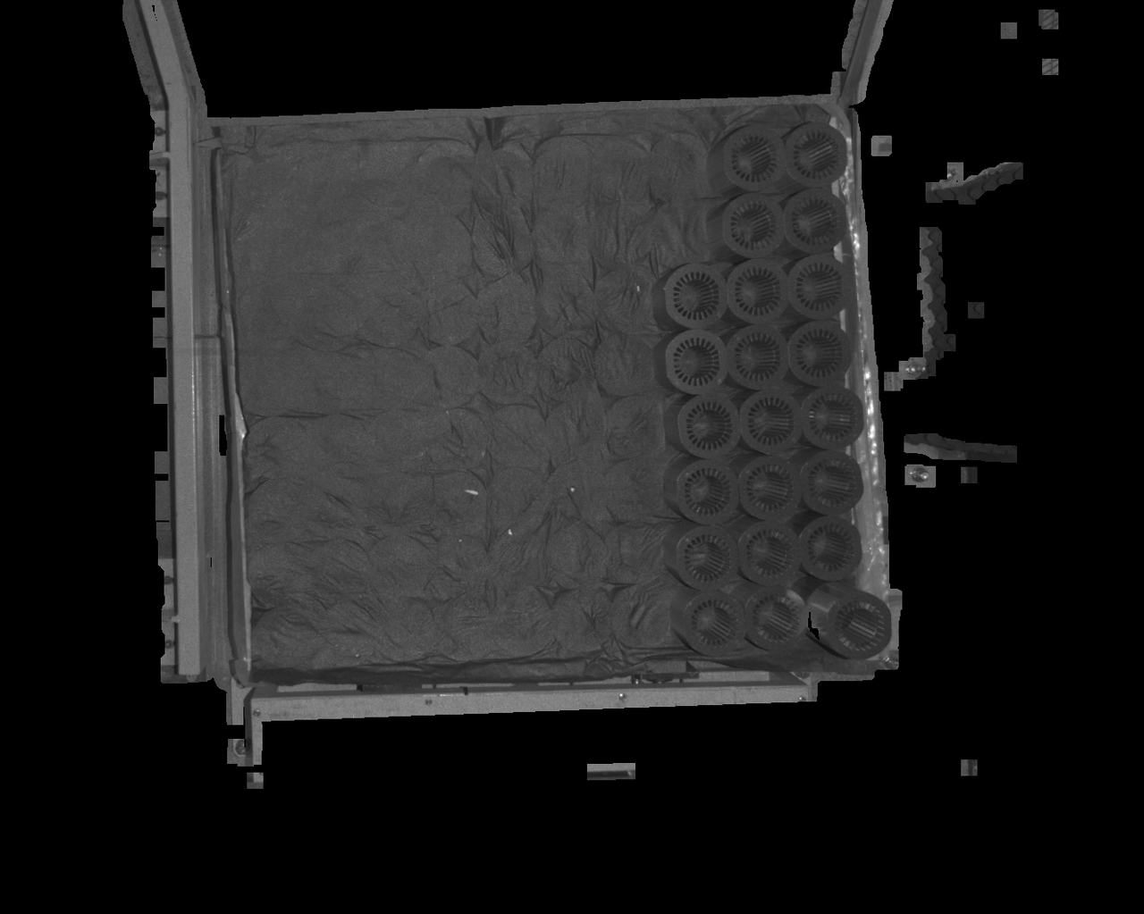 After the filling kernel setting is increased, the black holes in the detection area are significantly reduced, and the detection effect becomes better After the filling kernel setting is increased, the black holes in the detection area are significantly reduced, and the detection effect becomes better | 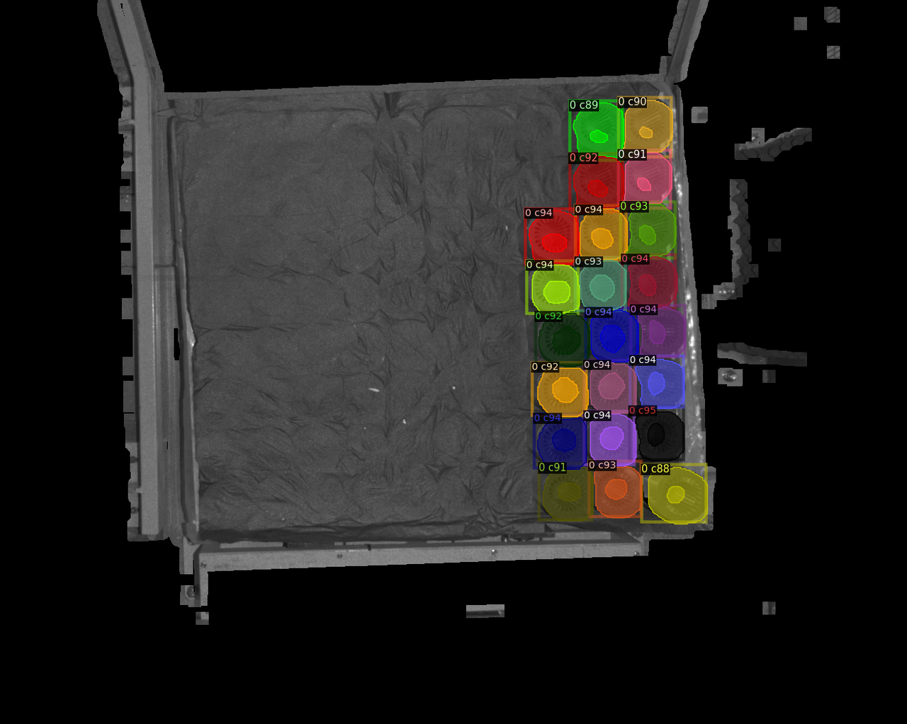 |
4.1.9 model not recognized
Problem: The deep learning model cannot recognize the last layer of Target after grabbing it.
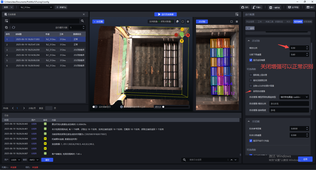
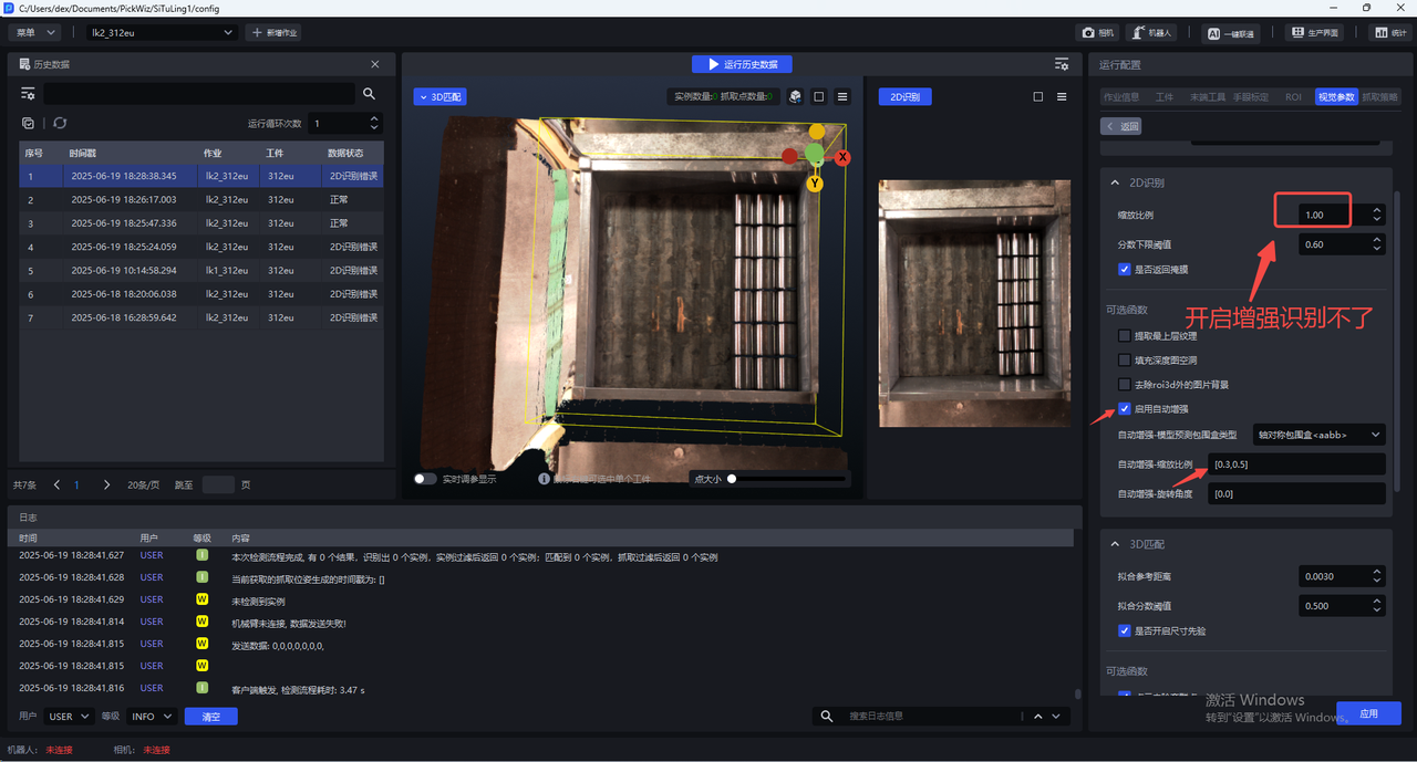
**Affected version:**1.6.1
Possible reasons: The glia version is glia 0.4.1, which is not suitable for the model
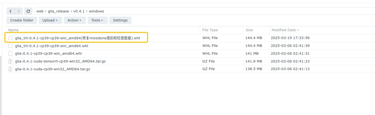
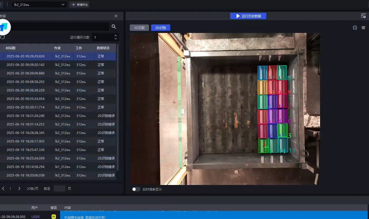
Solution: Download the repair package on the NAS system. After updating the glia version, the model can recognize the last layer.
4.2 CPFV
Facial Target Visual Parameter Adjustment Guide
4.2.1 CPFV No test result
Question: The test failed and there is no test result for CPFV.
Solution:
Check whether there are non-subject noise points in the template Point Cloud. The viewing method in meshlab is as shown in the figure. When the outer bounding box is larger than the expected template Point Cloud, it means that there is undeleted noise.
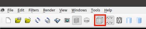
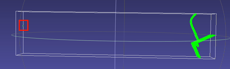
When prompted that no gesture is detected, you can give priority to bootstrap_percentageParameter and adjust it to 1. If the matching is accurate, consider reducing and adjusting the Cycle time through parameters such as downsampling.
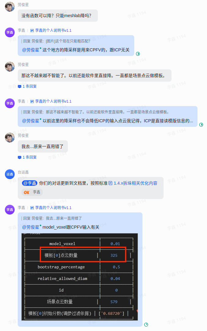
Check whether the magnitude of the template Point Cloud matches the Scene instance Point Cloud (instancepcd) before downsampling (it is recommended to use the undownsampled ScenePoint Cloud as the template Point Cloud. The input Point Cloud of the attitude estimation during ScenePoint Clouddownsampling also undergoes corresponding downsampling processing)
Check whether model_voxelParameter is consistent with ScenePoint ClouddownsamplingParameter in preprocessing
Try to lower model_voxel and ScenePoint ClouddownsamplingParameter in preprocessing at the same time to increase the number of matching points.
When the downsampling of the template Point Cloud and ScenePoint Cloud are consistent and the number of Point Clouds is both 200+, detection failure still occurs. This may be due to the difference in normal vectors between the template Point Cloud and ScenePoint Cloud (mainly may occur when using outline mode, which has been fixed in the 1.5.2 version). You can open meshlab and drag it into Point Cloud to check the consistency of the normal vector between the template and the instance Point Cloud. If the normal vector consistency is high but the detection still fails, contact the industrial research support
Meshlab View Point Cloud Normal Vector Method
Drag into Point Cloud
Select the Point Cloud where you want to view the normal vector and click render in the upper left corner
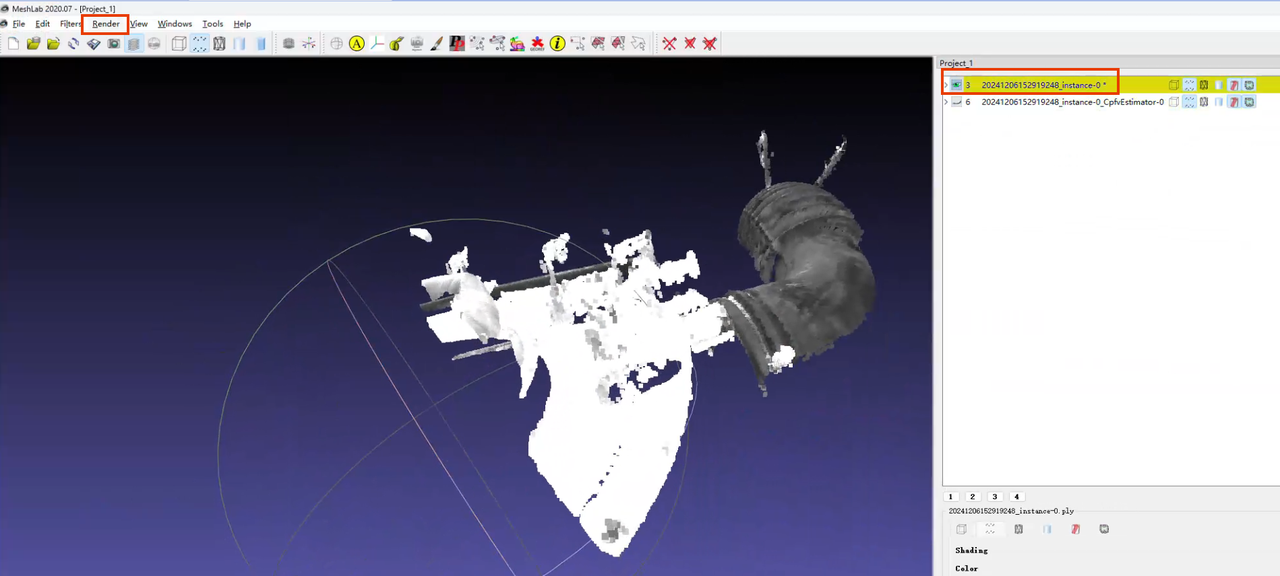
Click show normal in the render drop-down list
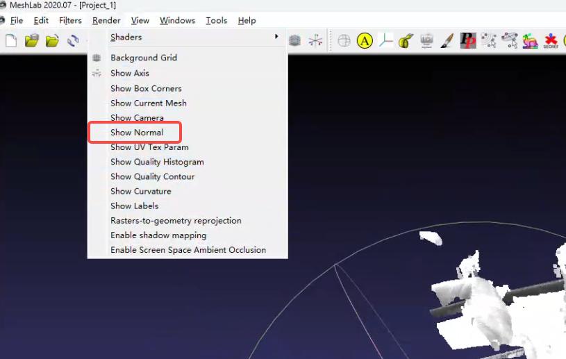
Color size can be set in the lower right corner
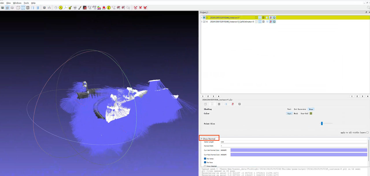
4.2.2 model positioning accuracy is poor/repeat positioning accuracy is poor
Problem: Poor accuracy, poor model positioning accuracy/poor repeated positioning accuracy
Solution:
When the matching is inaccurate, you can give priority to bootstrap_percentageParameter and adjust it to 1. If the matching is accurate, you can consider reducing and adjusting the Cycle time.
Check whether Parameter sets the direction prior, and test whether canceling the direction prior is effective.
After the software backend PickLight version 1.4.0, the default CPFV does not perform ICP fine registration processing. Check whether the icp_process function exists in the post-processing of the attitude estimation node. For function usage, please refer to [Facial Target Visual Parameter Adjustment Guide] (../视觉参数/面型工件视觉参数调整指南.md)
Software version <= 1.4.2, attention! When there is an icp_process post-processing function, the visualization result of attitude estimation needs to be turned on icp_processParameter "save_data": true and observed in the pose_refine folder. That is, the Point Cloud registration result in the existing Pose folder ≠ the final attitude estimation result. You cannot rely on this position Point Cloud to conclude that the attitude estimation is inaccurate
Software version >= 1.4.3 later. The ICP registration results are saved in the two Point Cloud files with the poserefine suffix in Pose/output.
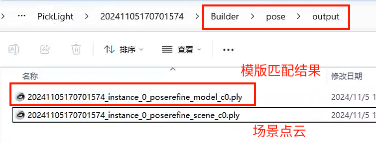
After using the ICP function, the accuracy visualization results are still not satisfactory. You can try changing icp_mode="Plane" in the icp_process function.
When the positioning object is small, reduce the icp_dist=0.xxx in the icp_process function according to the log prompt
When matching multiple photos of the same Scene but there are differences in the results, check the consistency of the Point Cloud in the multiple photo results (whether there are spatial changes in the key features of the Point Cloud due to multi-angle photos)
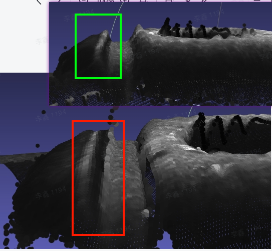
Check and remove the noise points in the Point Cloud template (sometimes in the ScenePoint Cloud)
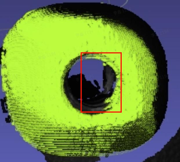
4.2.3 model positioning is rotated
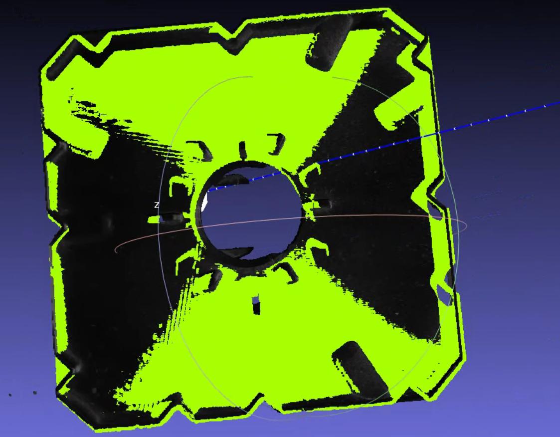
Problem: The angle is not good/there are accuracy requirements for the angle, and there is rotation in the model positioning
Solution:
When the Target is a rotationally symmetric and consistent object, there may be rotation that causes the RZ to rotate 180 degrees. If the Target incoming direction is always consistent, it is recommended to set the CPFV direction a priori to [1,0,0,0] to maintain registration uniformity. If the Target incoming direction is not consistent, no prior is added, and the bound_euler_angle function is added. For function description, please refer to the document 3.1Crawling Strategy Adjustment Guide [to be updated]
- "prior_direction": [[1,0,0,0]]
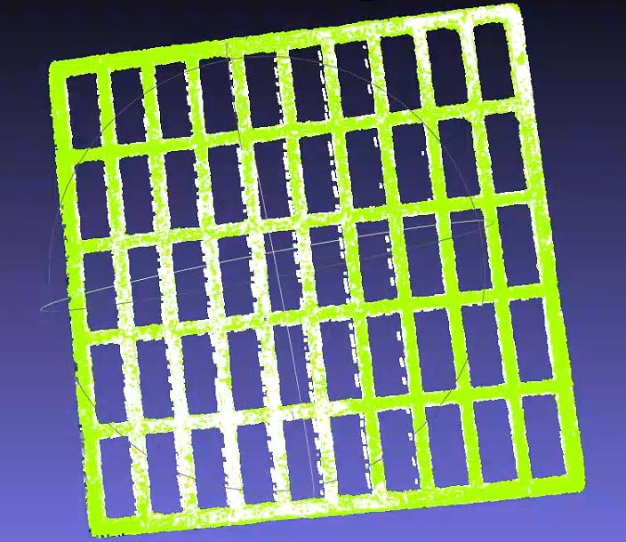
Add the refine_pose_by_z_axis_rotation function to correct the rotation pose in the post-processing part of Pick Point generation node (after 1.4.2)

Function Parameter usage reference document link [Facial Target Visual Parameter Adjustment Guide] (../视觉参数/面型工件视觉参数调整指南.md)
4.2.4 Registration Cycle time does not match the expected Cycle time
Problem: The beat is not good, the registered Cycle time does not match the expected Cycle time
Note: It is currently believed that CPFVCycle time is generally controlled within 2 seconds (1 second for detection, 1 second for precise registration)
Solution: As long as the matching accuracy allows! Adjust the following Parameter (it is recommended to test the matching accuracy or check the visualization results after each adjustment)
The detection time in the inspection log is as shown below. The detection time represents the CPFV time-consuming. The attitude estimation time-detection time is regarded as the post-processing ICP time-consuming.


When CPFV takes a long time:
Adjust the downsamplingParameter to control the number of template Point Clouds and ScenePoint Clouds in the reference data to around 200, which has better results.
bootstrap_percent5age 0-1, speed 1 is the slowest, 0.1 is the fastest; stability 1 is the best, 0.1 is the worst; it is recommended to lower 0.1 each time, **Generally, the minimum adjustment is
Check relative_allowed_diamParameter=0.04
When post-processing ICP takes a long time:
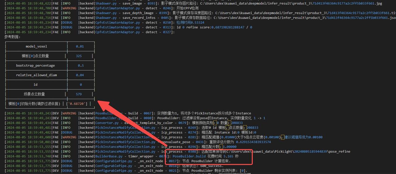
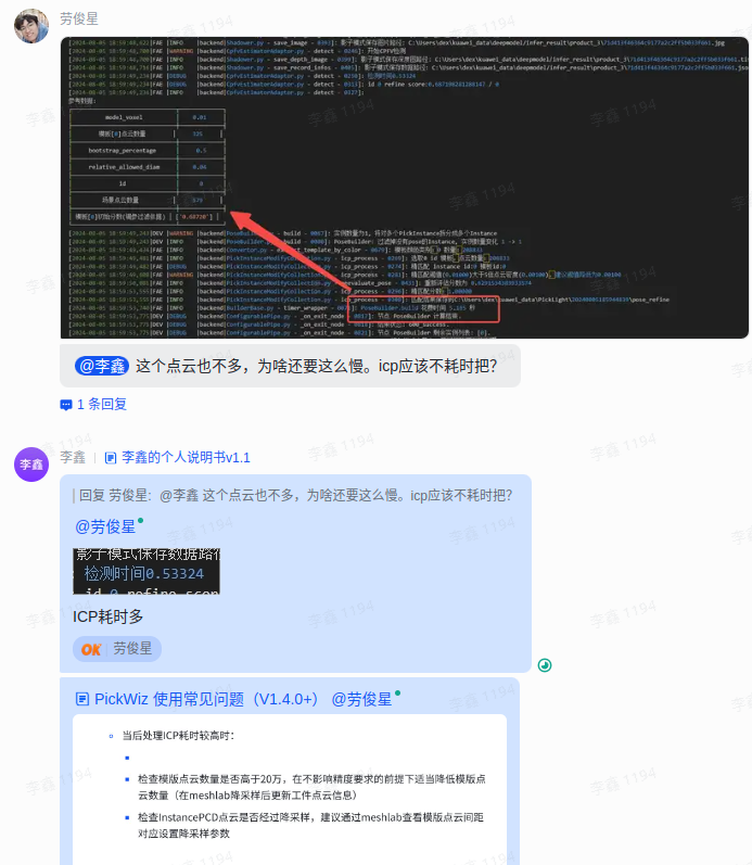
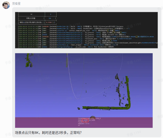
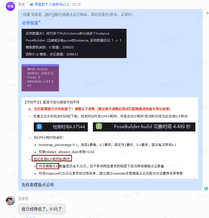
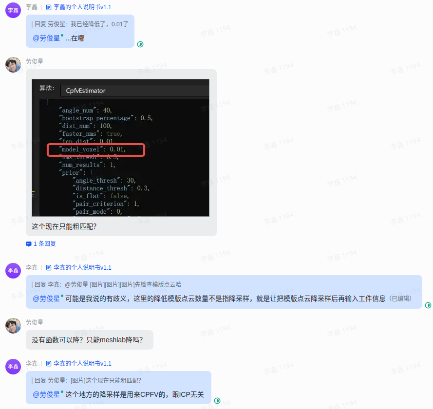
Check whether the number of template Point Clouds is higher than 200,000, and appropriately reduce the number of template Point Clouds without affecting the accuracy requirements (update TargetPoint Cloud information after meshlabdownsampling)
Check whether the InstancePCDPoint Cloud has been downsampled. It is recommended to check the template Point Cloud spacing corresponding setting downsamplingParameter through meshlab.
4.2.5 plane Target matching produces offset sliding
Problem: Matching offset, flat Target matching produces offset sliding
Solution: First confirm whether the size of the target Point Cloud will change in all directions. If so, you need to confirm that there is no change in the main body.
Take the template as shown in the figure and fill in the rough registration template in the Target attribute.
Add icp_processParametermode_path="Fine registration template file path"
- Windows paths recommend double backslashes or forward slashes

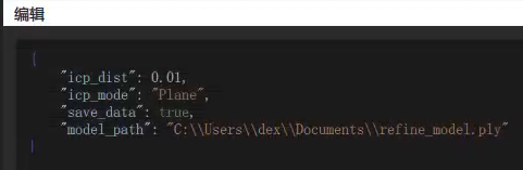
{
    "icp_dist": 0.01,
    "icp_mode": "Plane",
    "save_data": true,
    "model_path": "C:\\Users\\dex\\Documents\\refine_model.ply"
}
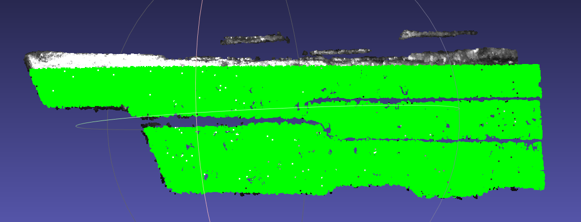
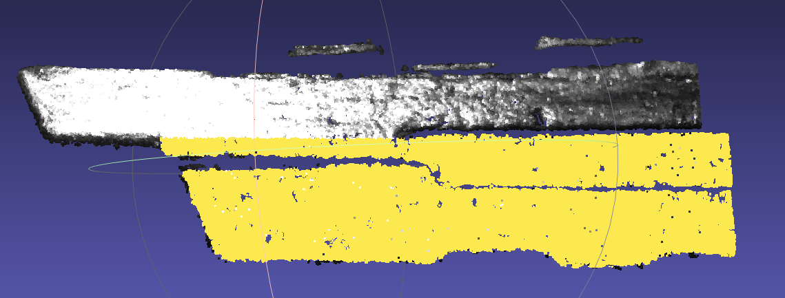
ScenePoint Cloud (the size in the red box will change) Coarse registration template (it is recommended to have more scenes on the right) Fine registration template (take the unchanged area) 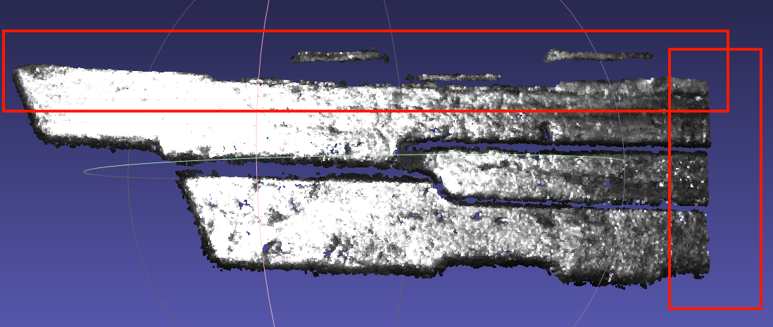
Increase the extraction of edge points
cpfv preprocessing adds function get_boundary_points
{
    "angle_threshold": 90,
    "max_nn": 30,
    "radius": 0.005
}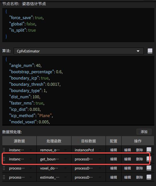
warn! When using get_boundary_points, please change the downsampling input data type
cpfvParameter adds boundary_type type
{
    "angle_num": 40,
    "bootstrap_percentage": 1.0,
    "boundary_type": 1,
    "dist_num": 100,
    "faster_nms": true,
    "icp_dist": 0.01,
    "icp_method": "Plane",
    "model_voxel": 0.005,
    "nms_thresh": 0.5,
    "num_results": 1,
    "prior": {
        "angle_thresh": 30,
        "distance_thresh": 0.3,
        "is_flat": false,
        "pair_criterion": 1,
        "pair_mode": 0,
        "prior_direction": []
    },
    "process_in_roi": true,
    "refine": true,
    "relative_allowed_diam": 0.04,
    "scene_ratio": 1,
    "score_thresh": 0.5,
    "update_prior": false
}
When the on-site plane parts use boundary_type and there is still a smooth offset phenomenon, you can use the contour refine function (** currently exists in the branch cwy/add-boundary-refine, and will be merged into 1.4.x** later). The usage method is to add Parameterboundary_icp, boundary_thresh
Parameter description:
When boundary_icp is true, it means turning on contour refine. The default is false.
boundary_thresh is the radius Parameter for calculating the model outline. The default value is 0.005, which is consistent with the radiusParameter in preprocessing get_boundary_points. (The outline radius Parameter is recommended to be half of the downsampling coefficient, and should be adjusted according to the outline Point Cloud situation of the template and Scene in Builder/pose/input)
{
    "angle_num": 40,
    "bootstrap_percentage": 1.0,
    "boundary_type": 1,
    "boundary_icp": true,
    "boundary_thresh": 0.005,
    "dist_num": 100,
    "faster_nms": true,
    "icp_dist": 0.01,
    "icp_method": "Plane",
    "model_voxel": 0.005,
    "nms_thresh": 0.5,
    "num_results": 1,
    "prior": {
        "angle_thresh": 30,
        "distance_thresh": 0.3,
        "is_flat": false,
        "pair_criterion": 1,
        "pair_mode": 0,
        "prior_direction": []
    },
    "process_in_roi": true,
    "refine": true,
    "relative_allowed_diam": 0.04,
    "scene_ratio": 1,
    "score_thresh": 0.5,
    "update_prior": false
}
4.2.6 Experience: Single target precise positioning debugging
**Project name:**Suzhou Samsung-Positioning of screw holes at the bottom of the washing machine liner
Workflow Features
The Instance Segmentation node has no algorithm and only relies on ROI to select part of the target area.
Only rely on CPFV+ICP to register and accurately position the target
Project Requirements
Positioning accuracy <=1 mm
Total time required <=2 s
Theoretical debugging process
Prioritize positioning accuracy before considering reducing time consumption. Refer to [Detection Failure] and [Poor Accuracy]
It is recommended to debug the Camera until the Point Cloud quality is stable, and then collect ScenePoint Cloud data sets at different angles in the fixed ROI.
Compare the Scene data set uniformly to confirm the characteristic areas that appear 100%, and select the relatively "three-dimensional" part in the space as the Point Cloud template. If it is a planar target, it is recommended to use contour registration.
Adjust ScenePoint Clouddownsampling and CPFV+ICPParameter according to log feedback in actual use until the matching effect is stable
Test the repeated positioning accuracy. If the conditions are met, end the positioning debugging. Otherwise, continue to adjust the Parameter.
Accelerate CPFV+ICP on the basis that the positioning accuracy meets the conditions
Reference【Bad Cycle time】
If the attitude estimation node is adjusted to about 1 second, but the overall time-consuming is still longer than expected, you need to refer to [Algorithm Process Time-consuming Analysis] (https://dexforce.feishu.cn/wiki/OFyqwKjl3ilENMkFgrUcvCmDnjd) to analyze the cycle time, and then submit a request to consult the production research department for other possible speed-up operations.
Specific debugging issues and experiences
Problem 1: Matching offset + high time consumption
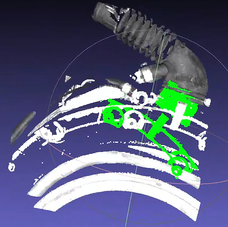
The on-site feedback attitude estimation matching results are as follows, green is the template matching result, white is ScenePoint Cloud
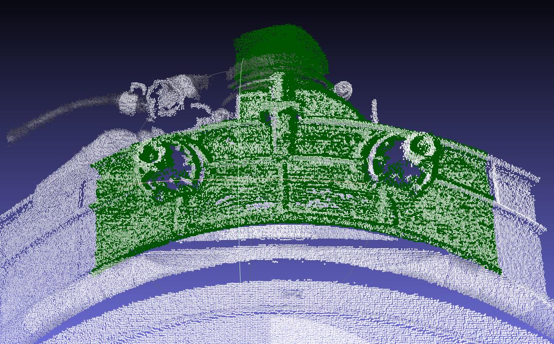
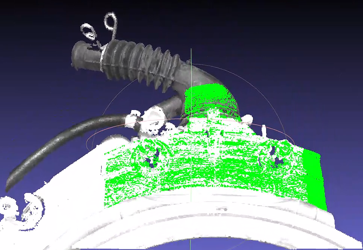
First check the coincidence between template Point Cloud and ScenePoint Cloud
It is found that the main body of the pipe at the top of the picture is missing a lot in the ScenePoint Cloud.
The larger body is the plane in the middle of the figure, and there are similar planes on both sides of the plane part Point Cloud
Since the relative relationship between the ROI and the target is not fixed, the template plane part on a certain side may exceed the ScenePoint Cloud
Determine the cause of match offset
Due to the point pair matching characteristics of ICP, more similar points will cause the head of the template T-shaped to "sway" to the left and right of the ScenePoint Cloud position, while the main body of the tube at the tail of the T-shaped cannot be effectively "fixed" by the ScenePoint Cloud, resulting in possible deviations.
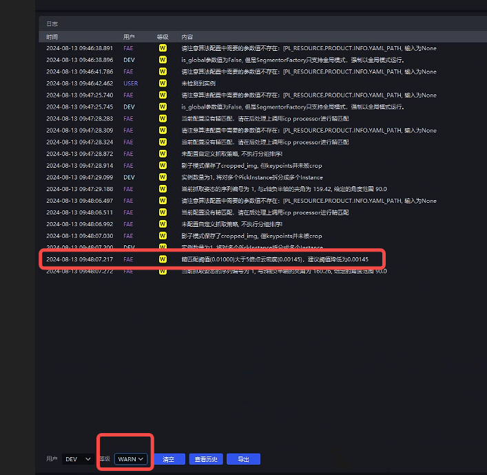
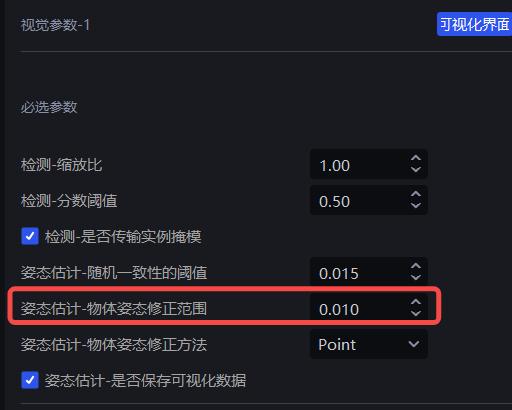
In addition, icp_disThreshold is set to 0.01 by default, causing the template Point Cloud to think that points close to 10mm away from itself are "own people", which increases the randomness of matching.
Solution 1:
Set icp_dis=0.002 to reduce the randomness of the movement of the template Point Cloud
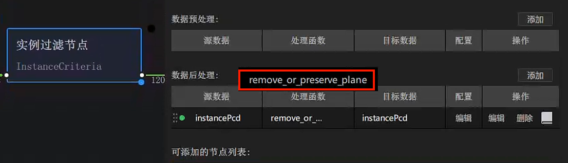
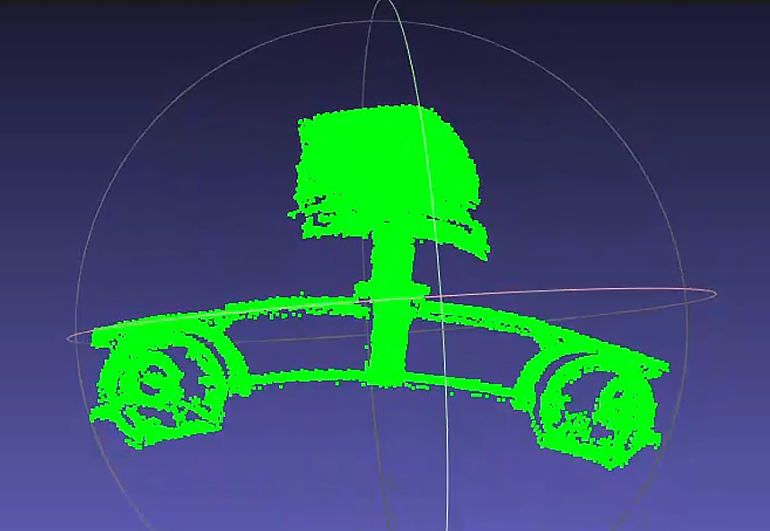
Adjust the Point Cloud template for plane removal, and add remove_or_preserve_plane in the post-processing of the instance filter node to reduce the abnormal impact of missing plane parts on matching. The Parameter settings are as shown in the figure. When actually creating a new one, there will be an extra "return_params" Parameter, just delete it.
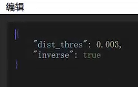
dist_thresThickness setting of point cloud fluctuation in view plane
When inverse is set to true, the plane is removed, otherwise the plane is retained.
Create a new template based on Point Cloud that removes the plane
Adjust CPFV and preprocessing downsamplingParameter to improve speed. You can directly refer to [Poor Cycle time]
Problem 2: Low matching and repeat positioning accuracy
Attitude estimation results are seriously misaligned
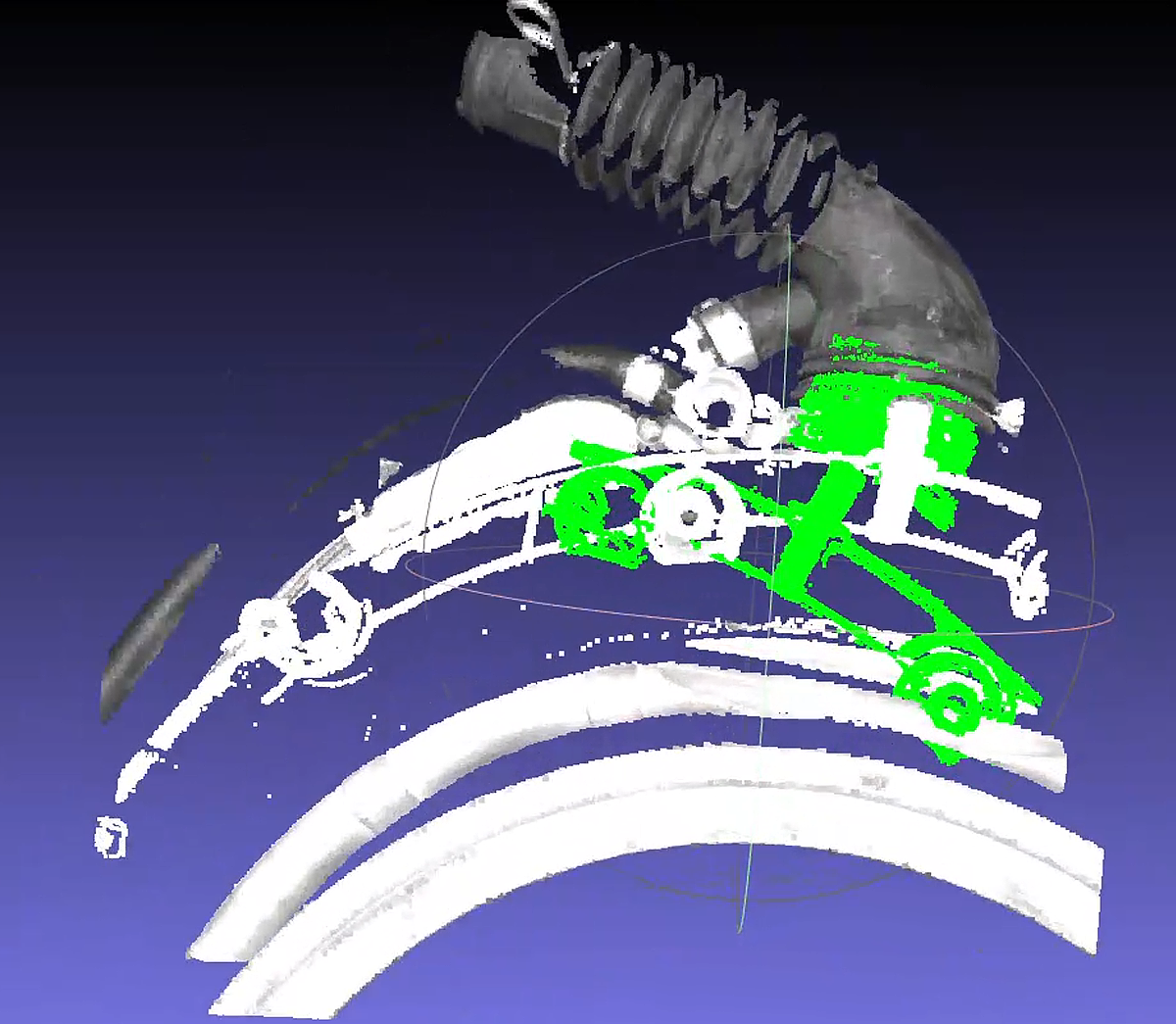
Check the coarse registration Point Cloud situation
The CPFV rough registration result of the new template may be poor, resulting in ICP being unable to obtain correct results.
It was found that there is a serious gap between the point spacing between the template Point Cloud and the ScenePoint Cloud. The inspection found that model_voxel=0.01 and voxel_size=0.02Parameter are significantly different.
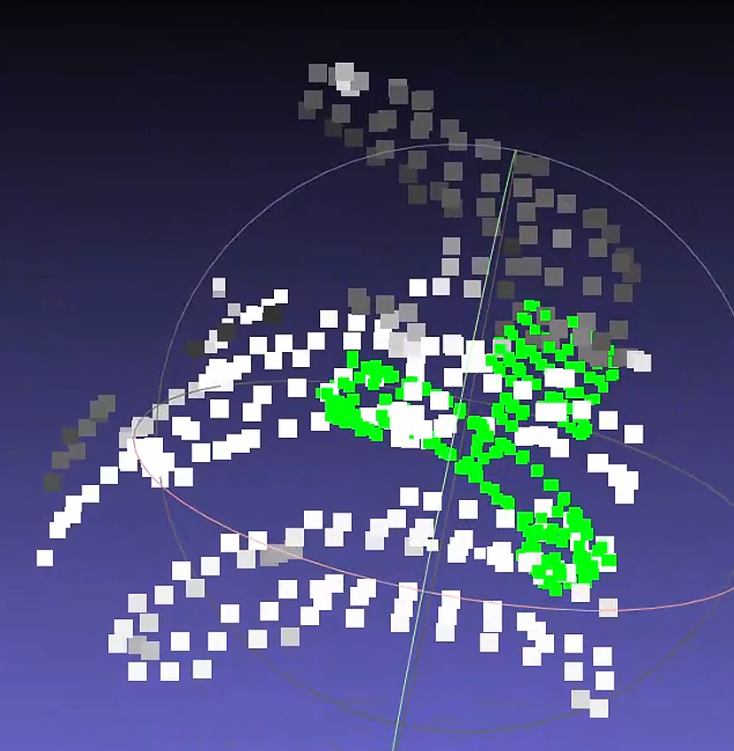
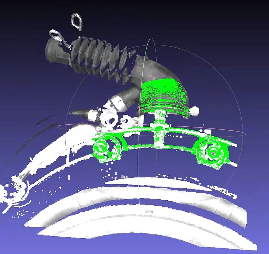
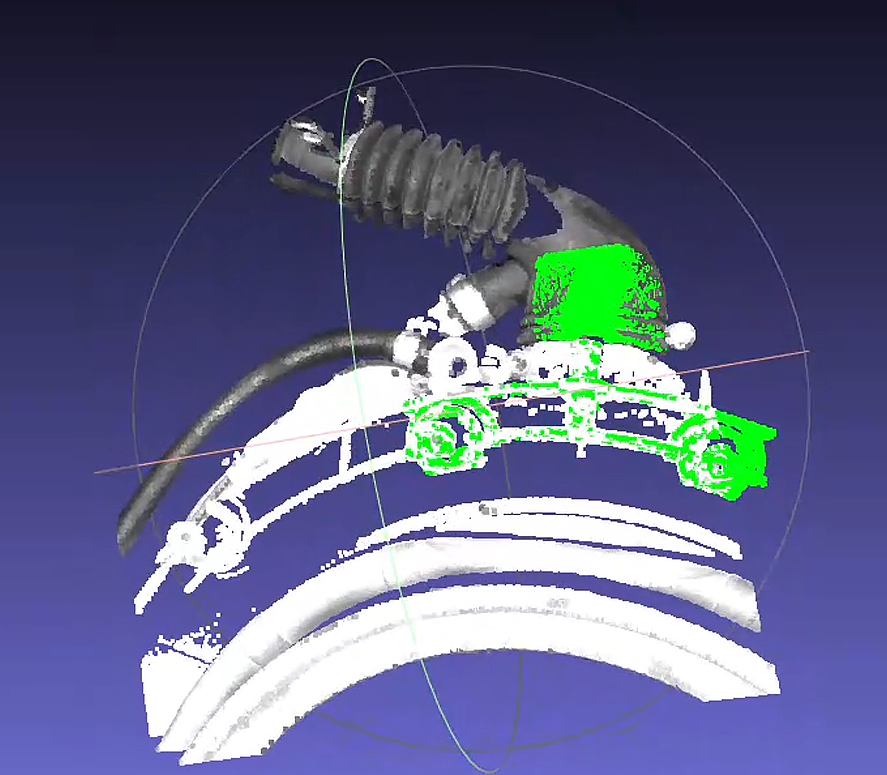
Solution 2:
- Adjust the preprocessing downsamplingParameter=0.015 to make it close to CPFV's "model_voxel"=0.01
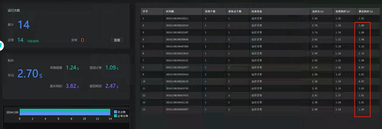
After the correction, 13 pieces of historical data were tested and matched normally. Camera was used to shoot 10 times on site. The repetition accuracy met the requirements. The algorithm took about 1 second.
Notes
**The main body in the new template is changed from a flat surface to the front end of a black tube, so it is still necessary to ensure that no matter what angle the material is fed, this part must be within the ROI, otherwise it may still cause matching deviation! **
4.3 PNP
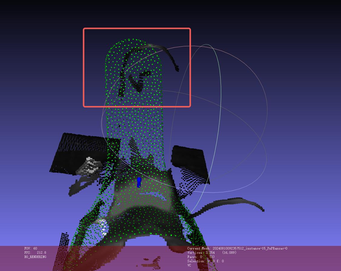
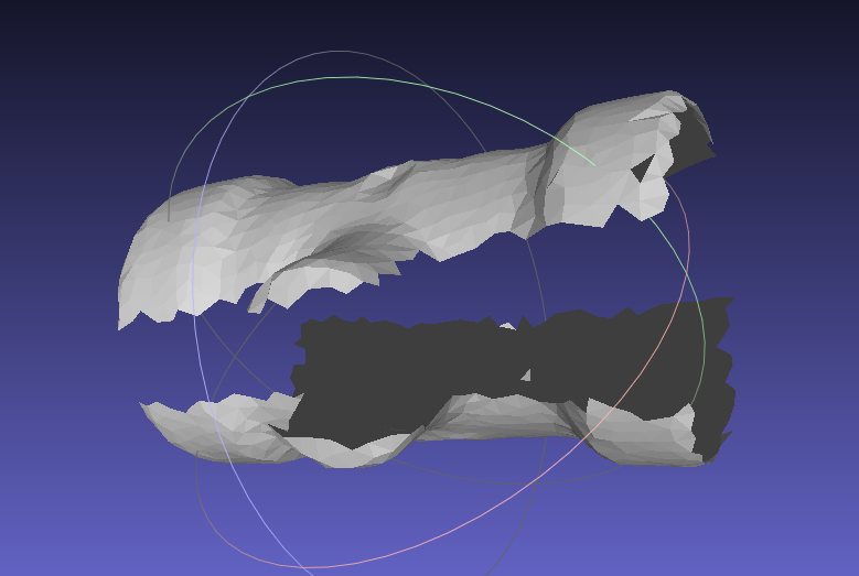
4.3.1 Inaccurate match/reverse match
Problem: Inaccurate matching/reverse matching occurs during the matching process
Solution:
Check the template Point Cloud and delete the interfering Point Cloud
Check whether the template Point Cloud and ScenePoint Cloud are exactly 180° opposite. If so, flip the template Point Cloud 180°.
 |
  |
|---|
4.3.2 match offset
Problem: CAD-based disordered grabbing, using SpatialRansac algorithm pose matching bias
Solution:
- Using the surface Target+cpfv algorithm, the model PCD (Point Cloud Data) is obtained by taking photos with the Camera.
When there is still inaccurate matching after using cpfv, refer to the following solutions:
Adjust CameraParameter to obtain high-quality Point Cloud images
Process the Point Cloud image after Instance Segmentation and use it as a Point Cloud template
Adjust the number of template Point Cloud and ScenePoint Cloud to control the number of Point Cloud between 200~400
Adjust bootstrap_percentageParameter to 1 and cancel the pose estimation pose angle prior
4.4 cylinder fitting PMFE
4.4.1 Pick Point angle is not vertical
Question: How to keep the Z-axis grabbing angle more perpendicular to human eye perception?
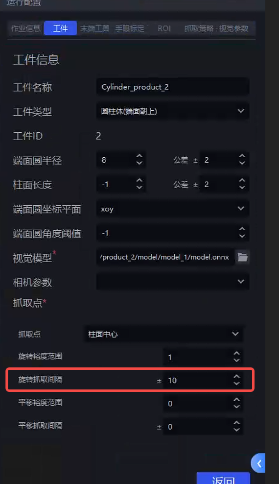
Solution: Reduce the rotation interval in the cylindrical Target attribute so that there is a Pick Point at every smaller angle on the cylindrical surface. Such Pick Points will be denser, that is, the angle difference between the most vertical Pick Point and the ROI Z axis or CameraZ axis will be smaller, as shown below:
4.4.2 The fitted Pick Point is not at the center of the cylinder
Question: How to ensure that the Pick Point is in the center of the cylinder
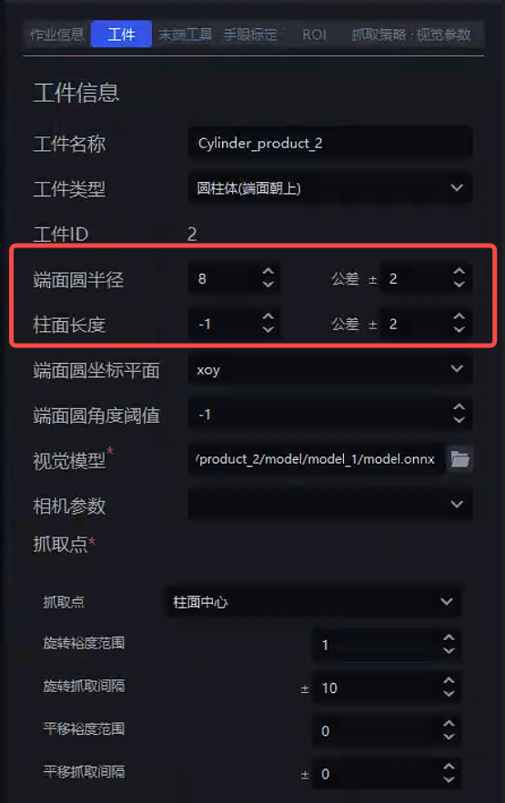
**Solution:**Set the radius prior and length prior in the cylindrical Target properties, as shown below (unit is mm)
4.5 Classification
4.5.1 cylinder adds orientation classification
Question: How to add a new column orientation classification?
Solution: If you want to make new materials, add the forward and reverse directions:
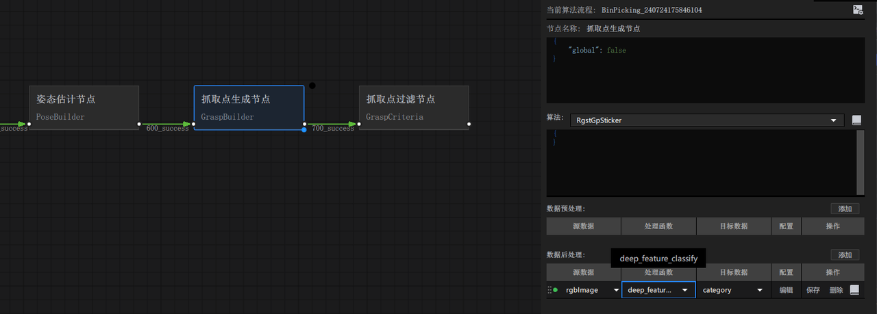
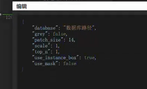
- For positive and negative classification of individual instances, first generate post-processing in Pick Point and add processor: deep_feature_classify, Parameter is as follows
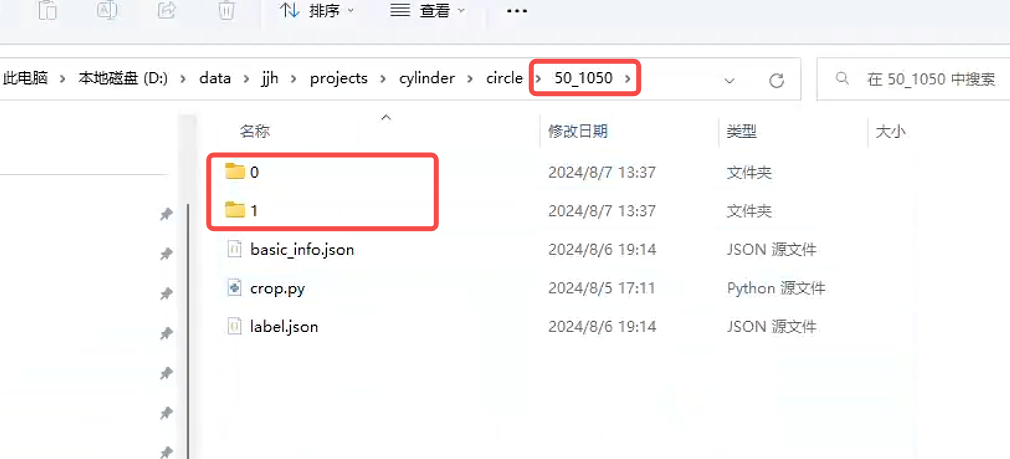
- Create a folder to store the positive and negative data, and create two named folders "0" and "1" under the created folder, as shown below
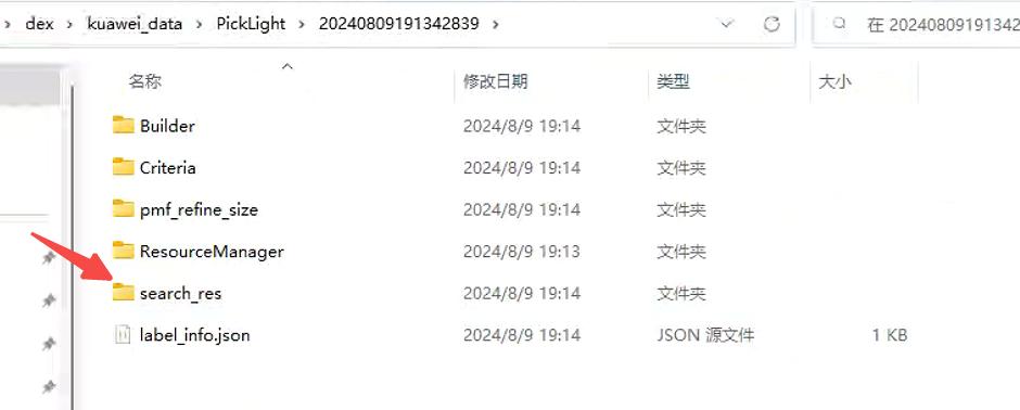
Then run the workflow and call deep_featrue_classify, which will automatically cut out the front and back pictures and store them in the historical data.
See the latest historical data in picklight
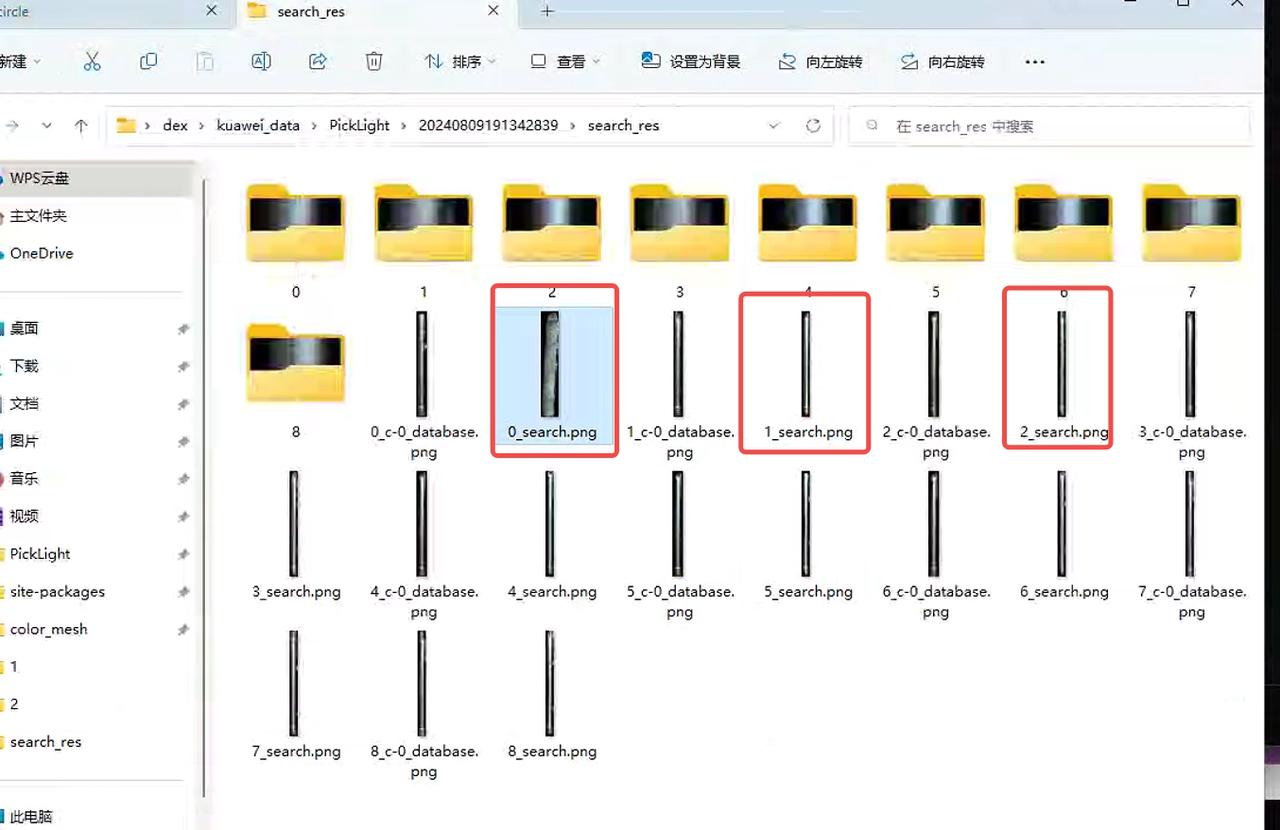
- Copy x_search.png, and create a folder named after the size of the material you want to add under the specified path. The most direct way is to copy the existing folder, and then clear the contents inside. There are two folders 0 and 1. After clearing, put the classified and oriented pictures into it (Tip: This step requires the operator to distinguish the positive and negative)
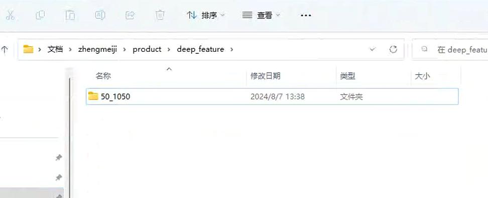
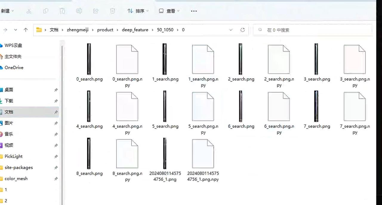
- Go to this path and execute these two commands. Remember to change the path to the material you want to add, so that the front and back templates are ready (path search method: open the folder named "New Folder 2" on the desktop, find the folder named "site-packages" on the left, click to enter, and create a new folder according to the path as shown in the icon)
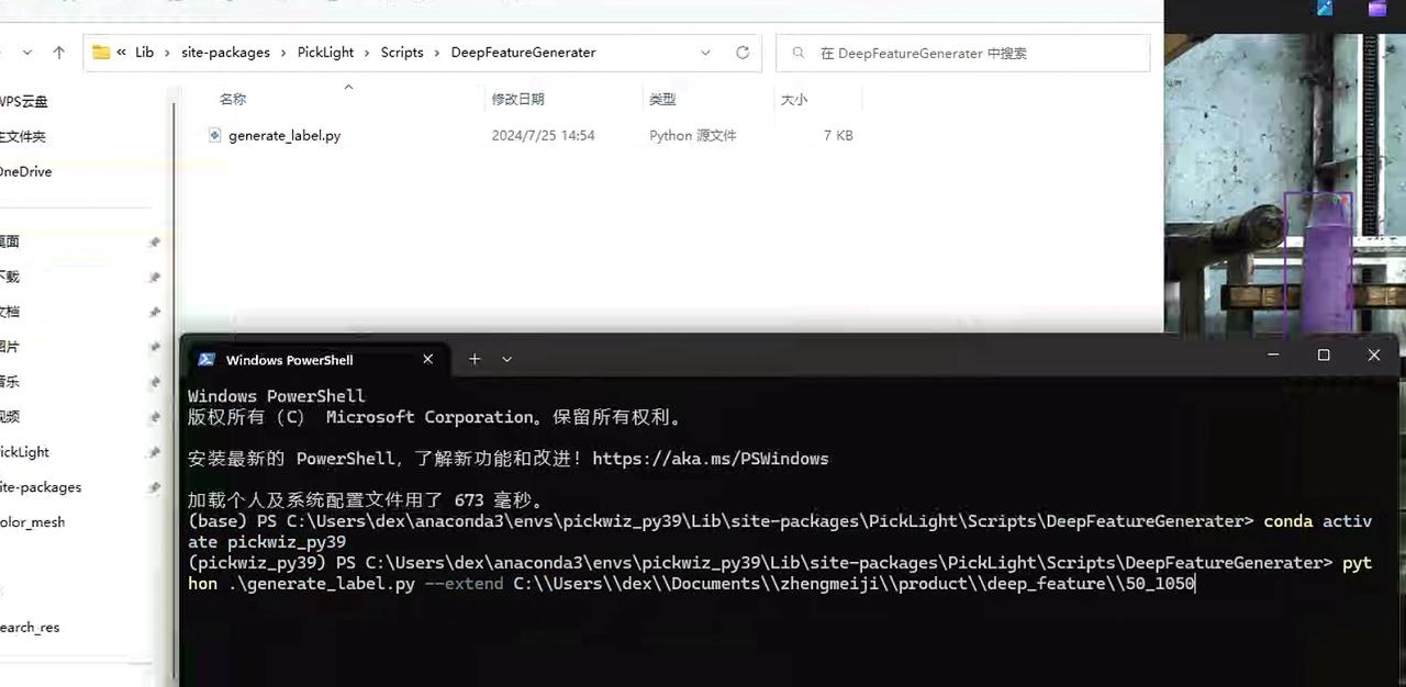
- If you want to add new ingredients, repeat this step from step 2.
4.6 wire harness workflow
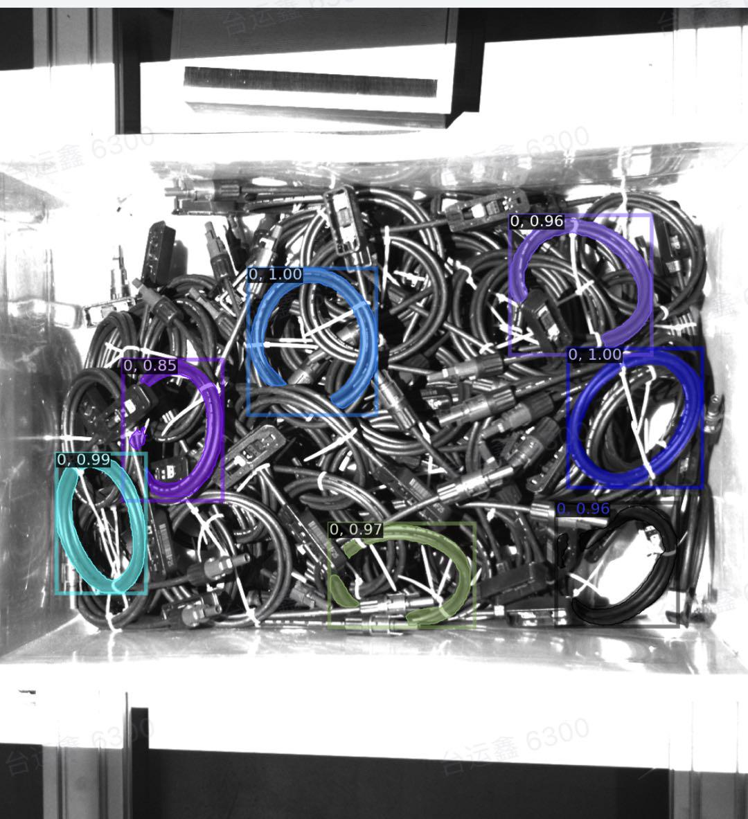
4.6.1 Camera configuration
To adjust the 2d exposure, the exposure needs to be large and the harness cannot look "completely black".
4.6.2 Target template
The extracted Point Cloud is used as a template and must be aligned with keypoints, mesh, etc. It can be operated using meshlab.
O-shaped wire harnesses generally have size differences. You can scale Cad and feature points at the same time. See Common Meshlab Operations to form a model equivalent to the actual wire harness size and register it in the software.
4.6.3 material frame detection
The buckle frame mouth, the refinement of the frame mouth buckle.
The Point Cloud storage address should be kept well; the material frame templates of different workstations are independent of each other.
In the background log, pay attention to searching backend.log and search for "container score" to see if the matching score is normal (usually above 0.3-0.4).
Matching patterns use Points.
If the material does not pass through the frame, please pay attention to additional processing.
In the output of the container node, the suffix icp represents the final frame matching effect; init represents the initial frame posture.
For specific usage documents, see Circle3D, IcpEstimator and CPFVParameter instructions
4.6.4 pose estimation
In the Wire Harness Scene, the matching mode uses Points.
After changing the Camera exposure, pay attention to changing the Processor. There may be color filtering causing abnormal Point Cloud filtering.
The running branch of the harness is the specific branch cwy/collection_add_collision_score (only for 1.2.x version, not required for 1.4.x version). In order to prevent the empty report box from being grabbed midway, fitness needs to be set to 0.
4.6.5 collision detection
Special treatment is required when setting the fixture, otherwise the phenomenon of "clamping the frame wall" will easily occur.
The height of the material frame must be set reasonably, otherwise the phenomenon of "mistaken collision" may easily occur, causing the material at the bottom of the frame to be ungraspable.
When the clamp scrapes the edge of the material frame, it is recommended to locate the cause of the problem to see if it is a positioning problem or a clamp size problem. The clamp can be enlarged. For the method, see Meshlab Common Operations.
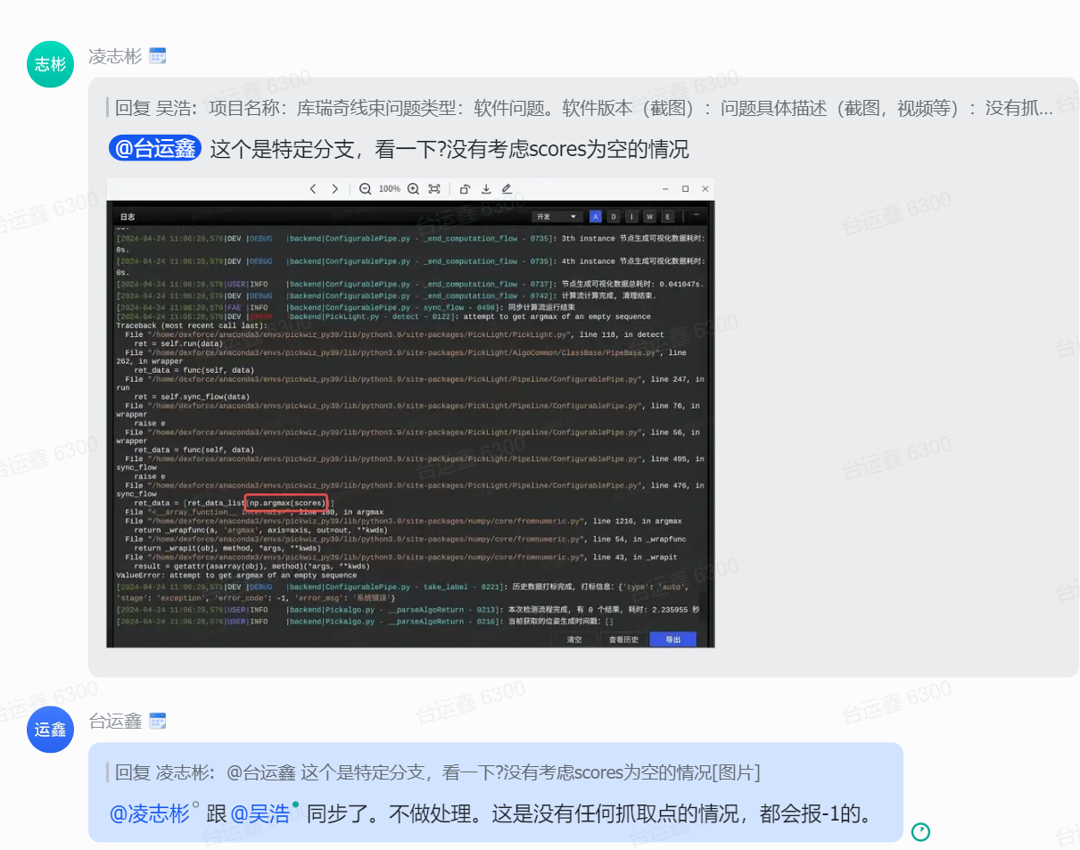
4.6.6 No Pick Point
4.6.7 Pick Point Settings
The x and y axes need to set the fixture coordinate system to the center of the harness Point Cloud.
The z-axis needs to be set on the Point Cloud surface and cannot be too high or too low.
The rz angle needs to be adjusted correctly to match the actual clamping posture.
The rx and ry postures need to be set vertically with Point Cloud
In the case of eccentric fixtures, there are many collision detection filters, so symmetrical Pick Points need to be set to avoid collision detection.
4.7 crawl sorting
4.7.1 Sorting exception. Fetching is not in the expected order.
Solution:
- Checking whether the instance filtering function takes effect will reduce the number of instances participating in crawling and sorting. All instances need to be sorted to obtain the correct crawling order.
4.7.2 crawling strategy has a problem of crawling the lower layer
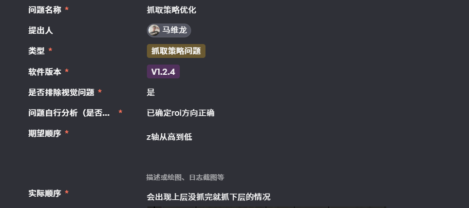
**Solution:**Follow the steps to check
Generate a visual graph of nodes based on instances to determine whether high-level instances are correctly segmented.
Confirm the node where the instance Point Cloud is generated. The crawling strategy sorted by height will be executed after this node.
If the crawling strategy is executed earlier than the instance filtering and the existing instances are sorted correctly, but the instance filtering node filters out some high-level instances (for example, if the Confidence is not high and is filtered), then these high-level instances will not be given later, and the performance effect will be to capture the lower layers.
Solution: Remove some unnecessary filter functions; train new models in shadow mode.