Collision Detection User Guide
The collision detection function is used to detect the collision between End-effector and material frame, and filter the grabbing gestures that may collide. This article mainly introduces how to configure the Scene Object and adjust the related visual parameters after turning on collision detection.
1. Operation Guide
1.1 material frame detection
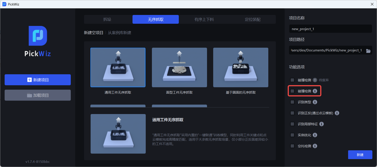
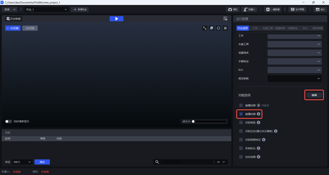
When there is a material frame in the actual Scene, when creating a new project, check the Collision Detection function; if it is not checked when creating a new project, in the Task Information Interface, click Edit on the lower right, then check Collision Detection and save
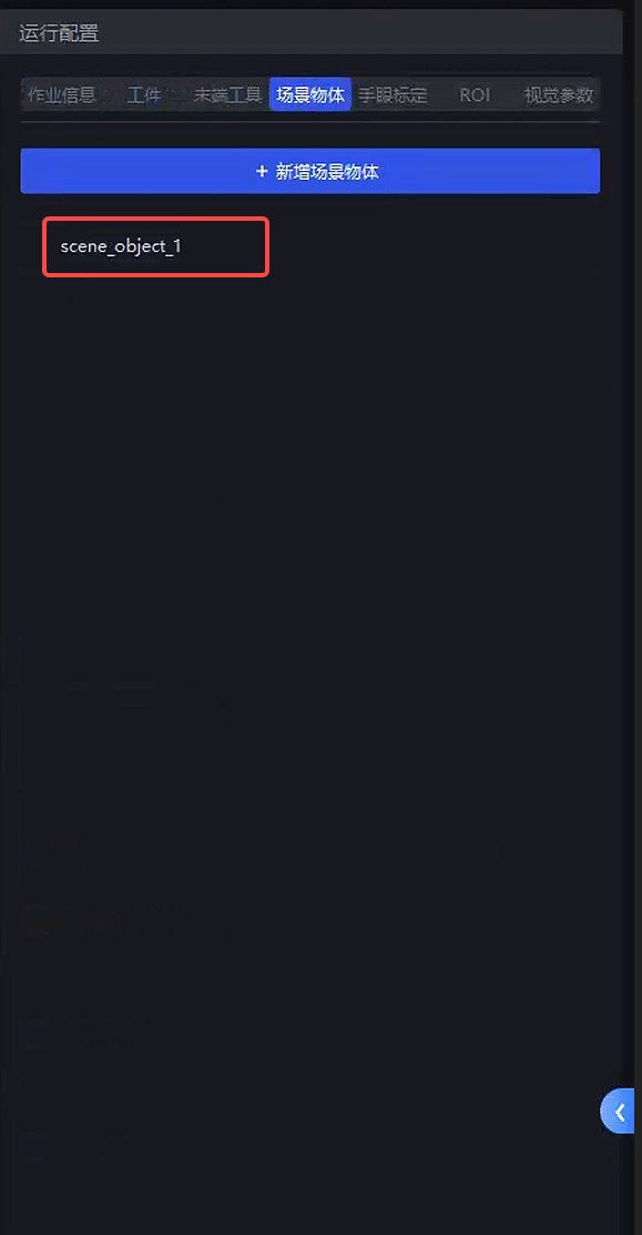
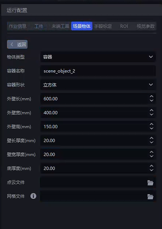
After checking Collision Detection, Scene Object will be added in the run configuration column. Fill in the outer wall length, width, height and thickness of the material frame in the Scene Object interface.
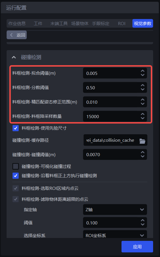
Adjust parameters related to material frame detection in Vision Parameter-3D Computing-Collision Detection. For details, please refer to 2.1 Material Frame Detection.
Collision detection between 1.2 End-effector and material frame
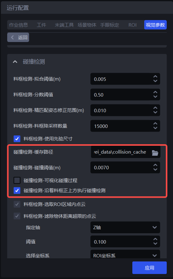
In 3D calculation-collision detection, you can adjust the Parameter. For details, please refer to 2.2 End-effector and material frame collision detection.
2. Parameter Adjustment Guide
2.1 Material frame detection
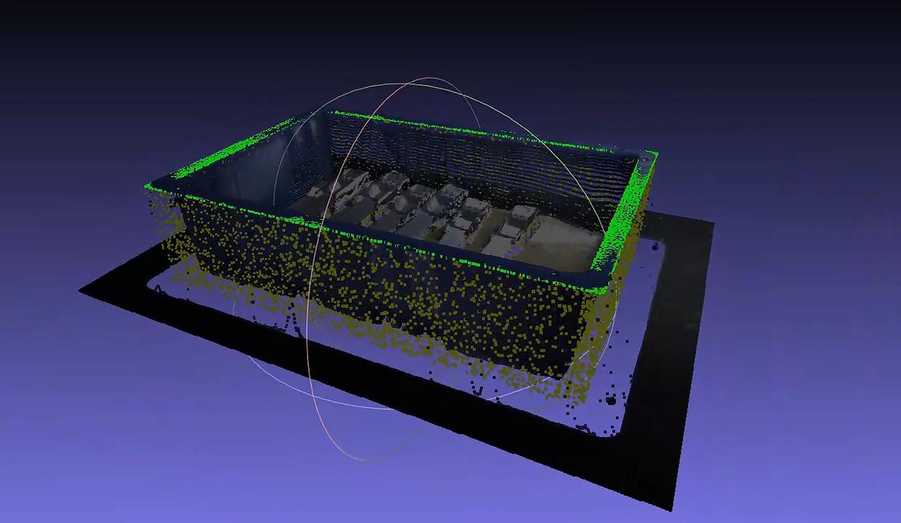
Material frame extraction process:
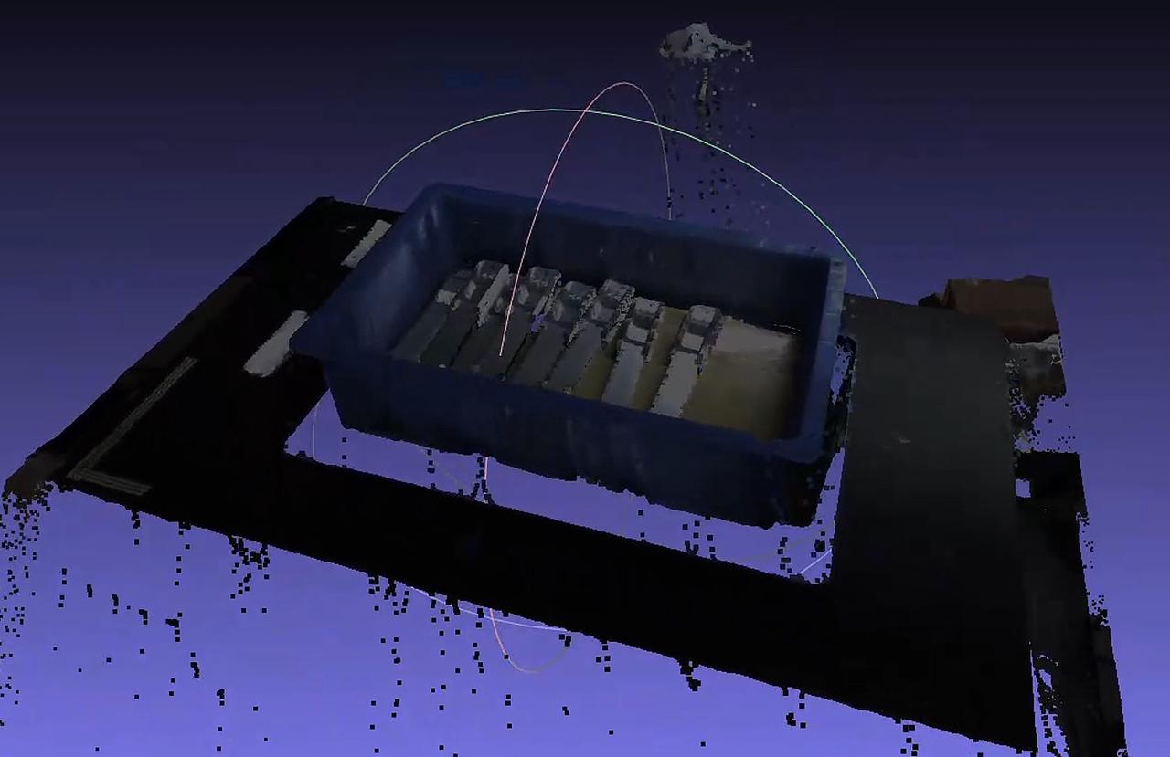
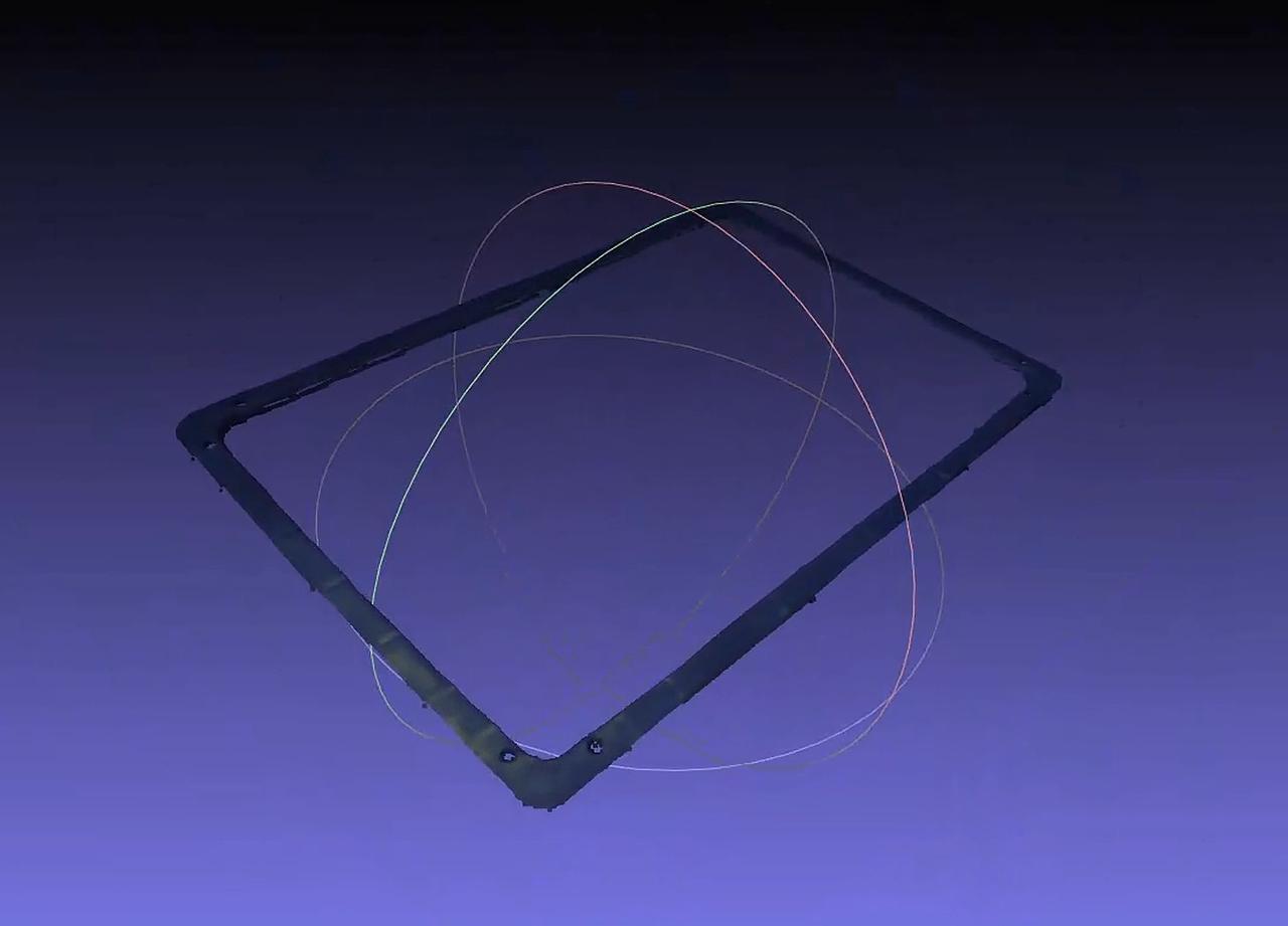
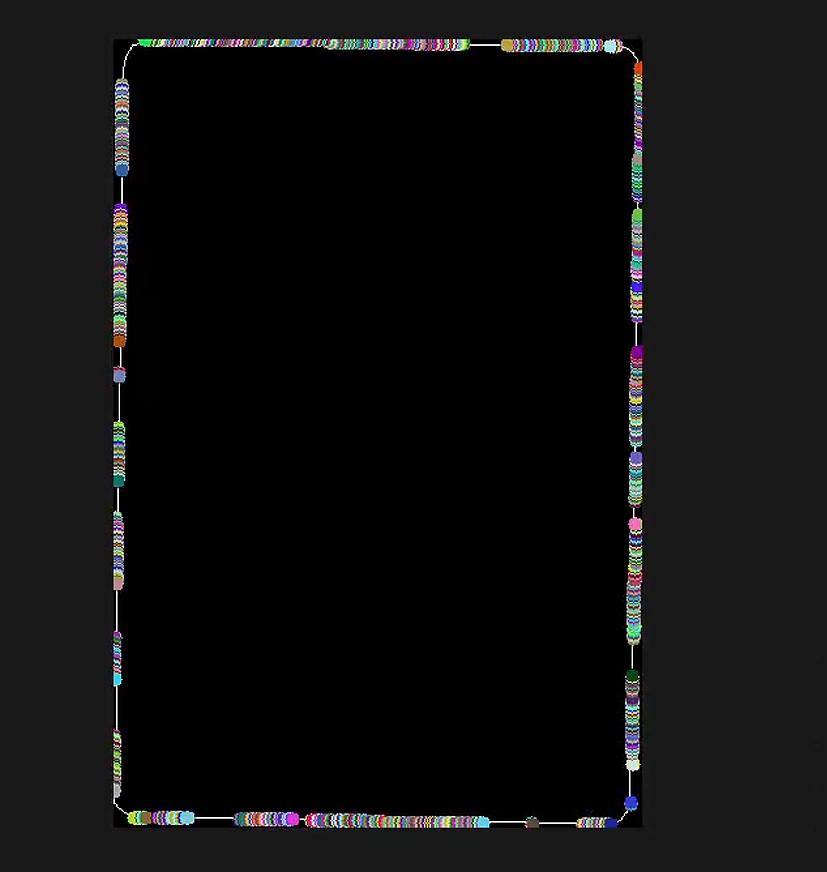
![3. According to the fitting Parameter, solve the material frame posture] (/static/pickwiz/碰撞检测使用指南/images/8b743cf2-de7f-4312-ac32-9f9884253ce8.jpeg)
| function | Parameter | Description | Default value | value range | Parameter adjustment recommendation |
|---|---|---|---|---|---|
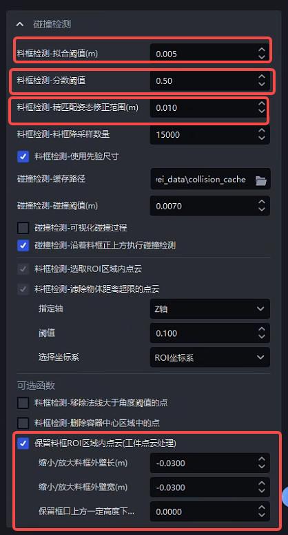
| material frame detection-fitting Threshold (m) | Fitting Threshold, based on the material frame size, determine whether the calculated material frame size is within the fitting Threshold | 0.005 | [0.001, 0.05] | between 0.003-0.01 | |
| material frame detection-score Threshold | The minimum score Threshold requirement for material frame detection. If the score is higher than Threshold, the material frame detection is considered successful. Otherwise, it fails. | 0.5 | [0.1, 1.0] | recommends 0.5 | |
| material frame detection-Fine matching attitude correction range (m) | When material frame is fine-tuned, the Point Cloud searches for the Threshold of the radius, and at the same time it is the distance Threshold for judging the correct point pair. The larger the value, the larger the search radius, and the more relaxed the conditions for judging the correct point pair. The default is 0.01, which generally does not need to be changed. | 0.01 | [0.001, 0.1] | generally does not adjust | |
| Frame Inspection - Frame downsampling quantity | material frame downsampling point value, used for Fine matching of the material frame. The larger the number of points, the faster the speed and the lower the accuracy. | 15000 | [5000, 30000] | is selected according to the accuracy requirements. The higher the accuracy requirements, the larger the number of points. | |
| material frame detection-using a priori size | Whether to calculate the material frame based on the prior size, if so, the material frame must satisfy the prior size and fitting Threshold, otherwise the maximum rectangle will be found as the material frame | Check | / | generally does not adjust | |
| material frame detection-select Point Cloud in the ROI area | Select Point Cloud in the ROI 3D area from the actual Point Cloud | Check | / | generally does not adjust | |
| material frame detection-filter out objects whose distance exceeds the limit Point Cloud-Threshold | specifies the axis | In the specified axis direction, based on 95% of the height of the Point Cloud of the material frame (the Point Cloud of the material frame from top to bottom is 100%~0%), remove the Point Cloud that exceeds the Threshold from top to bottom in the specified axis direction | Z axis | X/Y/Z axis | generally does not adjust |
| Threshold | Remove the Point Cloud that exceeds Threshold from top to bottom in the specified axis direction | 0.1 | [0.001, 1.0] | recommends between 0.005 - 0.2 | |
| Select coordinate system | specifies the coordinate system where the axis is located | ROI coordinate system | Camera coordinate system ROI coordinate system Object own coordinate system | generally does not adjust | |
| material frame detection-remove Point Cloud whose normal is greater than the angle Threshold | AngleThreshold | If the angle between the normal vector direction of the Point Cloud and the reference axis exceeds the angle Threshold, remove the point | 15 | [0, 360] | If the target plane is a flat surface, the angle Threshold is generally 5°~15°; if the target plane is a curved surface, the angle Threshold is usually 15°~30° |
| standard normal vector axis | reference axis (default Z axis, that is, vertical direction), an axis of the Camera coordinate system. | Z axis | X/Y/Z axis | generally does not adjust | |
| uses the ROI coordinate system | If checked, the ROI coordinate system will be used. If not checked, the Camera coordinate system will be used. | Uncheck | / | If the material frame is tilted, check the box to use the ROI coordinate system | |
| material frame detection-delete the point in the center area of the container | removal ratio | The ratio of the area of the center area to the area of the container, remove the Point Cloud in the center area, and retain the Point Cloud in the edge area | 25 | [0, 100] | Adjust according to the object area in the center area of the material frame |
| Is the X axis the long side? | If checked, the center area is calculated based on the length in the X-axis direction; if not checked, the length in the X-axis direction is compared with the length in the Y-axis direction, and the central area is calculated based on the longer side of the two. | Check | / | If the length in the X-axis direction is the long side, check it, otherwise do not check | |
| retains the Point Cloud in the ROI area of the material frame (TargetPoint Cloud processing) | Reduce/enlarge the outer wall length of the material frame (m) | When there is an error in the size of the material frame, causing a certain number of Point Clouds on the material frame wall to be retained, the Parameter needs to be reduced; or a certain number of Target Point Clouds are filtered out, and the Parameter needs to be enlarged. Negative numbers represent reduction, positive numbers represent enlargement. | 0.0 | [-1.0, 1.0] | generally does not adjust |
| Reduce/enlarge the outer wall width of the material frame (m) | When there is an error in the size of the material frame, causing a certain number of Point Clouds on the material frame wall to be retained, the Parameter needs to be reduced; or a certain number of Target Point Clouds are filtered out, and the Parameter needs to be enlarged. Negative numbers represent reduction, positive numbers represent enlargement. | 0.0 | [-1.0, 1.0] | generally does not adjust | |
| Keep Point Cloud (m) at a certain height above the frame opening | A space of a certain height above the frame opening can be set up. Point Cloud can be retained in the space to avoid the material frame overflowing the frame opening. | 0.0 | [0.0, 1.0] | generally does not adjust | |
**Example:**Retain the Point Cloud (TargetPoint Cloud processing) in the ROI area of the material frame to eliminate some reflective instances.
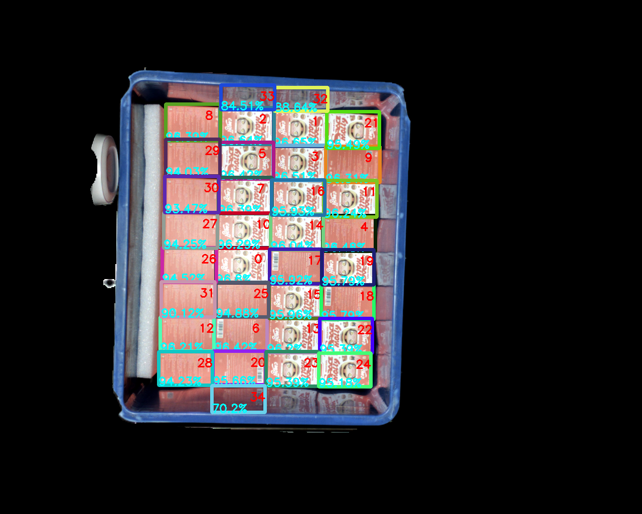
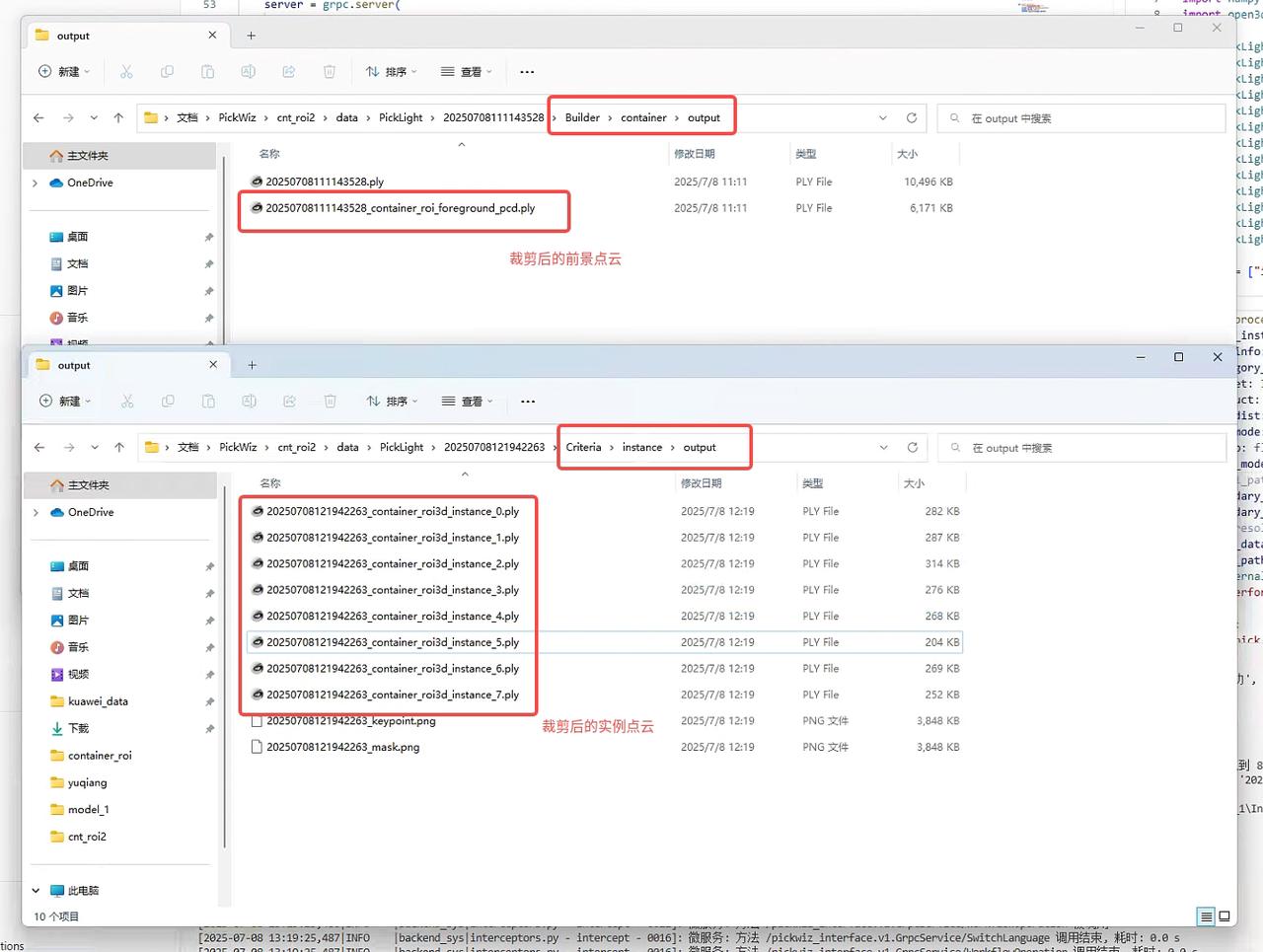
Exception description:
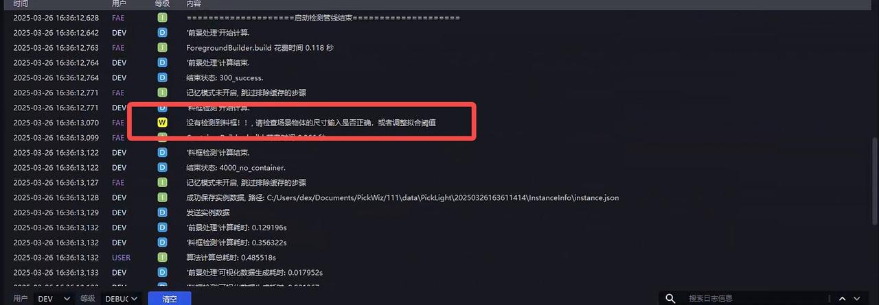
No material frame detected
No material frame is detected, first check whether the input material frame size is correct, and secondly adjust Material Frame Detection-Fitting Threshold (m)
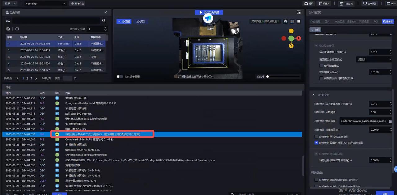
- Material frame detection score is too low
The material frame can be correctly identified, but the score is too low. You can relax the Material frame detection-Fine matching posture correction range (m)
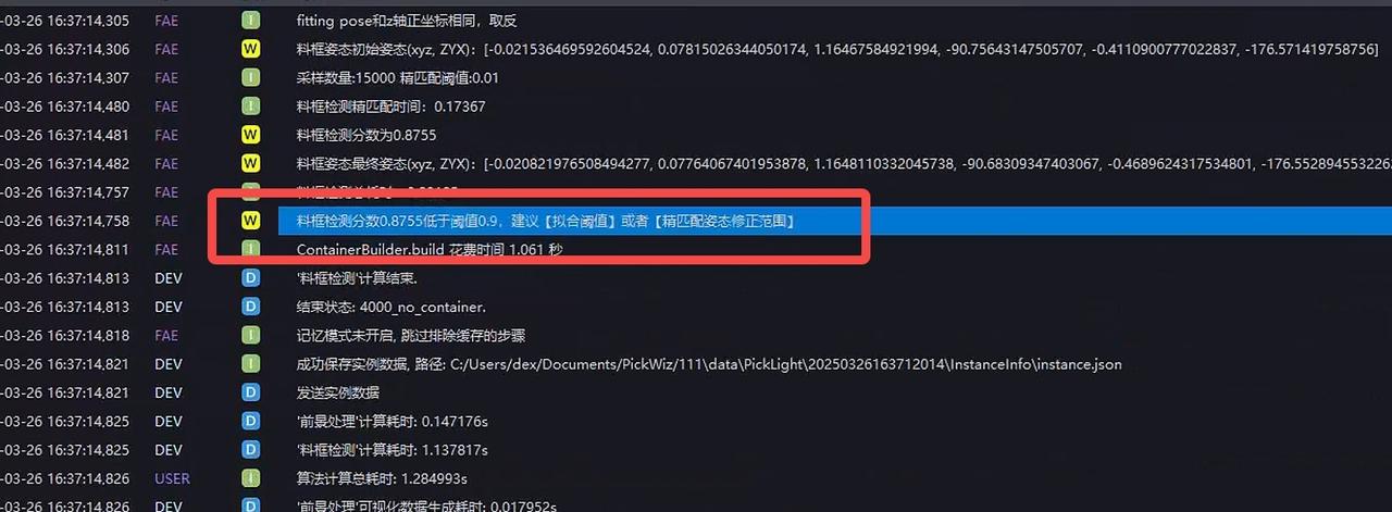
- The material frame score is lower than Threshold
The material frame score is too low. If it is recognized normally, modify Material Frame Detection-Score Threshold, otherwise modify Material Frame Detection-Fine matching posture correction range (m)
Collision detection between 2.2 End-effector and material frame
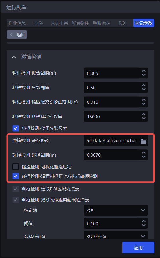
| Parameter | Description | Default value | Value range | Parameter adjustment suggestions |
|---|---|---|---|---|
| Collision detection-cache path | Collision detection visualization result saving path | / | / | |
| Collision detection - Collision Threshold (m) | Collision distance Threshold, if the distance between the Scene and the fixture surface is less than this Threshold, it will be considered to have collided | 0.007 | ||
| Collision Detection - Visualize the collision process | Visualize the process data of collision detection | Uncheck | / | |
| Collision Detection - Perform collision along the top of the material frame | Whether to perform collision detection along the top of the material frame. If not checked, collision detection will be performed along the negative direction of the Pick Point Z axis, that is, the fixture may move diagonally upward with an angle; | Checked | / |