One-click training of Imaging Model
The Imaging Model is a deep learning model that inputs the 2D images captured by the left and right cameras of the binocular KINGFISHER Camera and the CameraIntrinsic Parameter. The Imaging Model will analyze the parallax between the two 2D images, use the triangulation principle and deep learning technology to predict the depth information of each pixel in the Scene, and finally output the Depth image and Point Cloud data of the Scene.
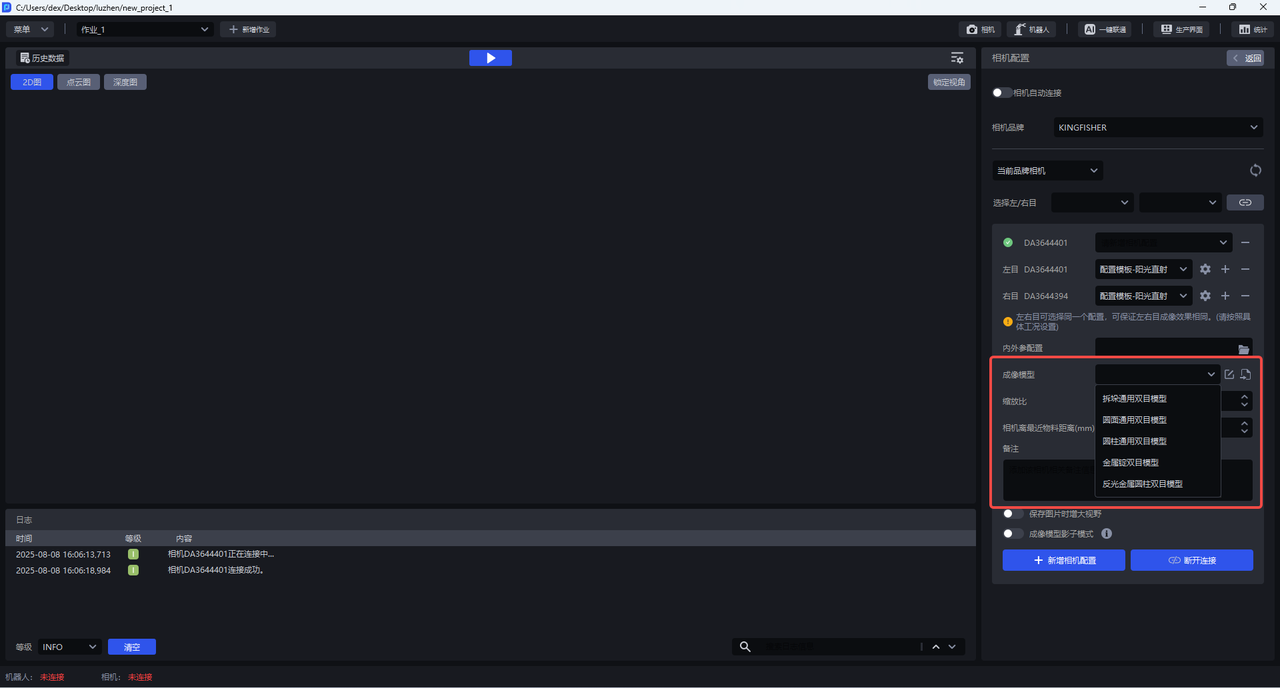
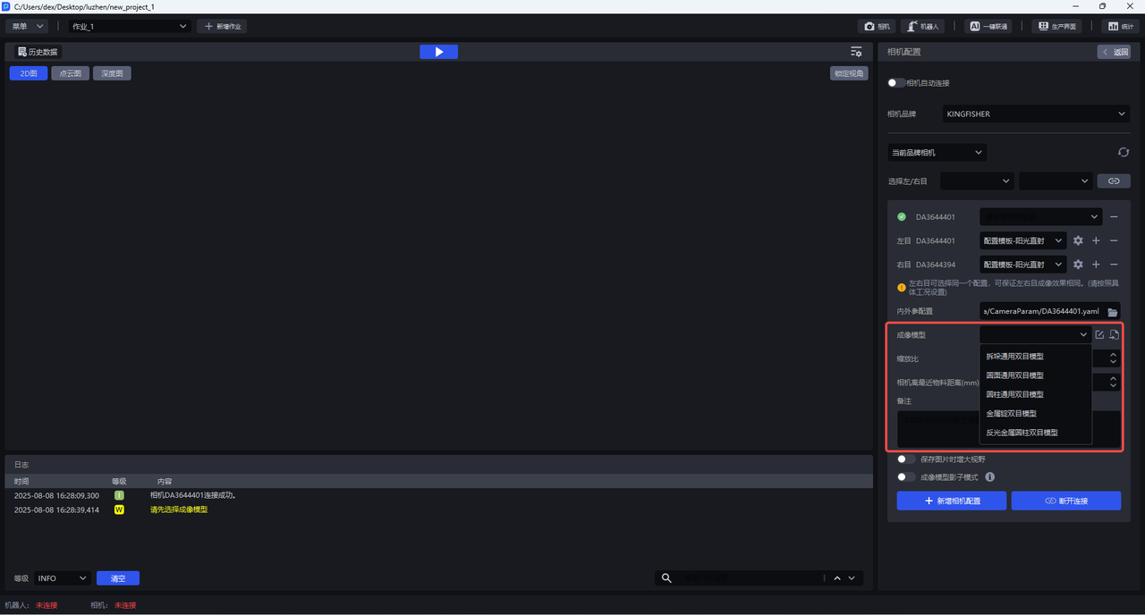
Binocular KINGFISHERCamera has five built-in universal Imaging Models, namely, destacking universal binocular model, circular surface universal binocular model, cylindrical universal binocular model, metal ingot binocular model, and reflective metal cylindrical binocular model. If these five general models do not meet the needs of the Scene, the Imaging Model should be specially trained for the Scene and imported.
If the general model of the binocular camera or the specially trained Imaging Model experiences Point Cloud collapse at the actual site, you can use one-click connection to further train and optimize the Imaging Model.
1. Select TaskScene
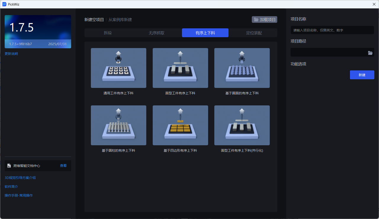
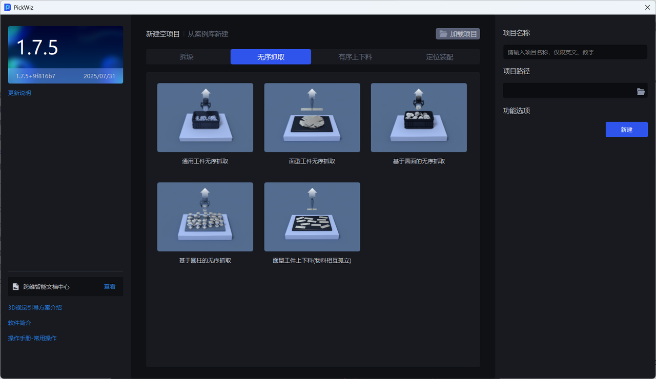
Binocular KINGFISHERCamera currently supports one-click training of Imaging Model in ordered and unordered scenes, and supports multi-type Target training (Function Options-Type Identification).
2. Configure binocular camera
2.1 Connect to binocular camera (if available)
After installing the binocular KINGFISHERCamera, PickWiz connects to the binocular Camera, sets the zoom ratio, selects the Imaging Model, and the minimum distance (adjust according to the actual situation).
(1) Connect the binocular camera
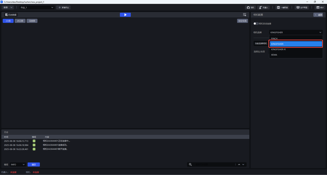
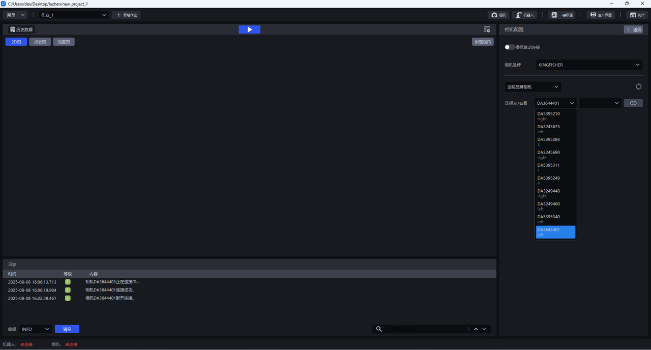
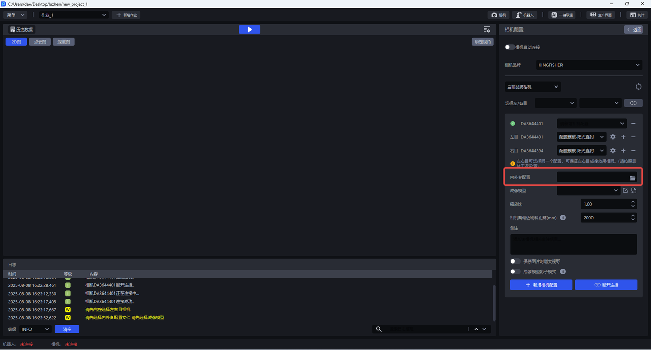
(2) Download the Extrinsic Parameter configuration file of the binocular Camera in [KINGFISHER-Camera Calibration File] (https://dexforce.feishu.cn/wiki/Qqcnw7aHWik2JNk2ZWbcCV0dn9k) and import it. The Extrinsic Parameter configuration file will be read in the training Imaging Model.
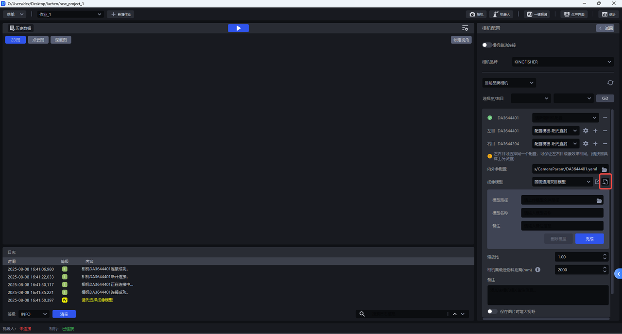
(3) Select a general model or import an Imaging Model specially trained for Scene. This model is the Imaging Model to be trained for one-click connection.
(4) Click +Add Camera Configuration
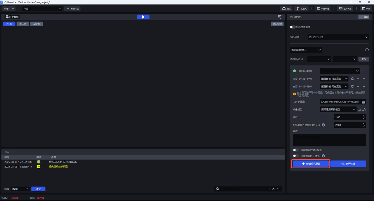
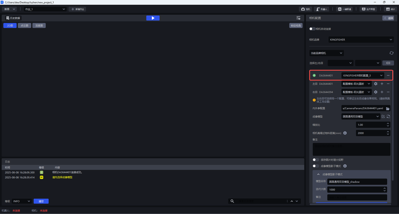
(5) Click Return and select the new Camera configuration in the Task information
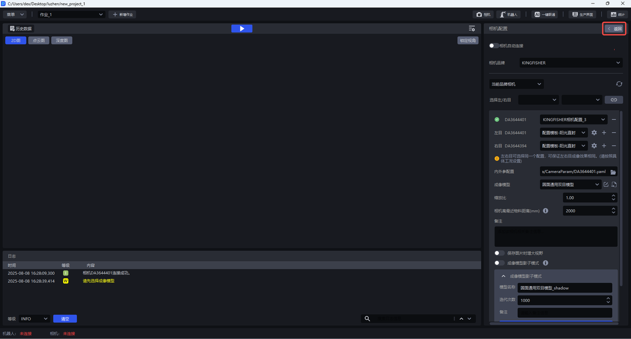
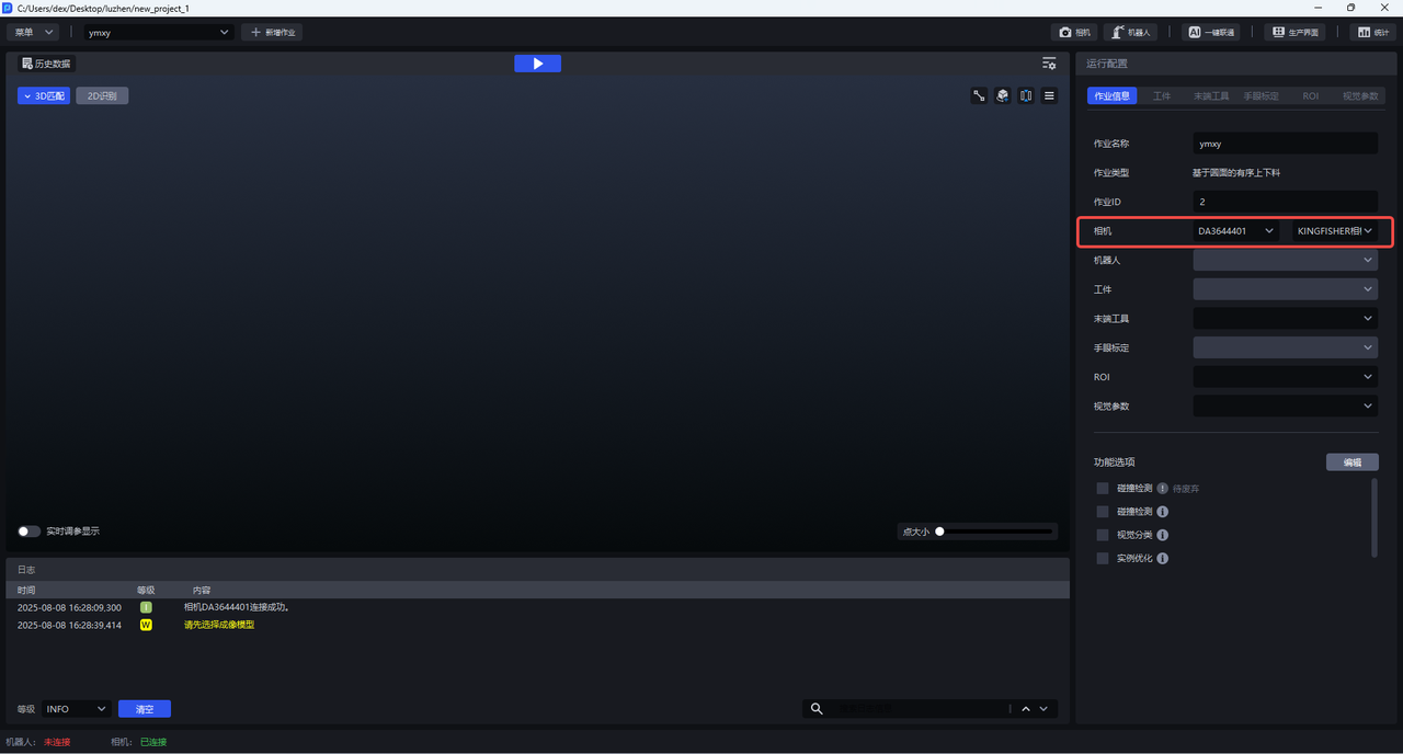
2.2 Select binocular Camera (if no Camera is connected)
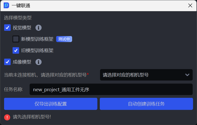
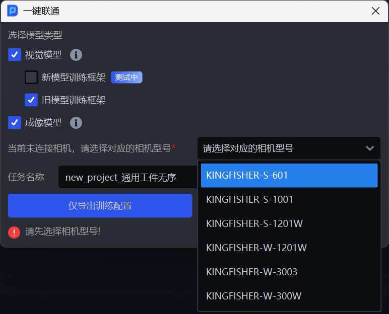
If there is no Camera connection, after completing 3. Configuring Target, 4. Configuring ROI, and 5. Configuring Scene Object, initiate one-click connection and select Imaging Model, you will be prompted that the Camera is not connected, and you can select the corresponding Camera model.
3. Configure Target
3.1 grid file
For general targets, surface targets, circular targets, cylindrical targets, and quadrilateral targets, when training the Imaging Model through one-click connection, grid files are relied on to render a large number of synthetic images under different viewing angles and lighting conditions, and expand the training data, which can improve the generalization ability of the Imaging Model.
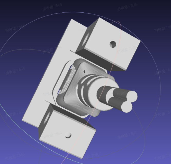
Upload the grid file and select the grid file size unit, meter (m) or millimeter (mm). If you are not sure about the unit of the grid file, you can leave it unselected. The system will automatically determine and convert it based on the uploaded grid file. After selecting, you can click Standardized Grid File. Currently, only grid files in ply format are supported.
Tips
Standardized grid file will implement the following four functions:
Automatically align grid files to coordinate centers
Mesh patch simplification
Adjust the Target to solve the problem of misalignment between the Target and the coordinate system
Uniformly adjust grid file sizes to meters (m)
Warning
Each time you click Standardize Grid File, it will be standardized again based on the last processed file.
In the Point Cloud template creation module, select grid file processing
The mesh pose can be adjusted as needed and synchronized to the Target of the current Task when exporting.
3.2 key point file
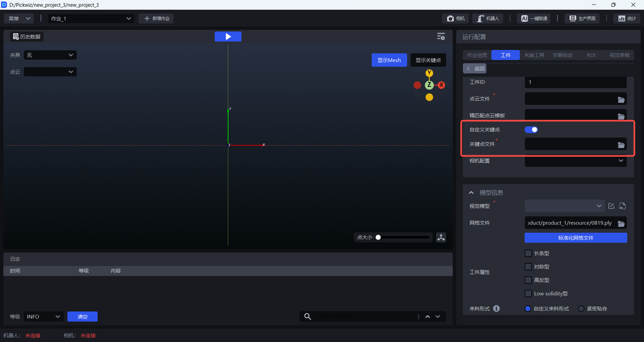
When training the Visual Model through one-click connection, the difference between the front and back sides of the general Target is large, so it is necessary to upload key point files for Front-Back Identification; the difference between the front and back sides of the face-type Target is small, so there is no need to upload key point files. Please refer to [Point Cloud Template Creation Guide] (点云模板制作指南.md) for the key points of creating a universal Target.
3.3 Target attribute
When training a Visual Model with a general Target and a face-type Target, you can check the `Target attribute'. One-click Unicom will generate training data that is more suitable for the Target characteristics based on these specified Target attributes. In this way, the trained Visual Model will have better recognition effects and higher robustness for Targets with specified attributes.
If you do not check the Target attribute, the generated training data will not specifically consider the specified characteristics of the Target (such as symmetry, high-reflection material, etc.), resulting in the recognition effect of the trained Visual Model that may not be ideal.
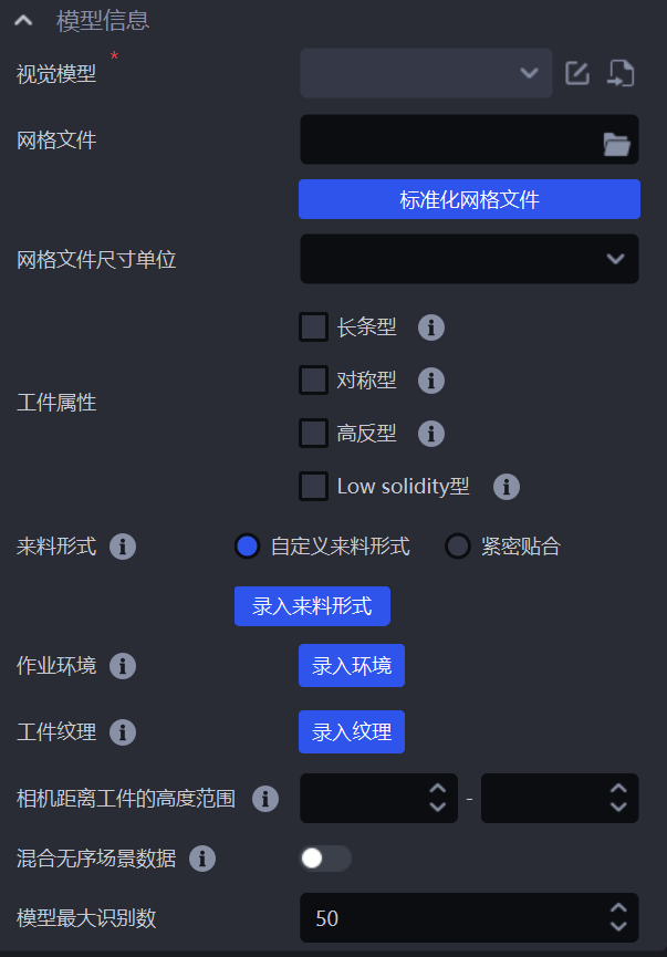
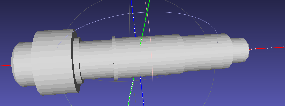
When the Target is a long-bar type Target: The Target aspect ratio exceeds 3:1, such as a long stick-shaped Target, you can check the Long Bar Type in the Target Properties;

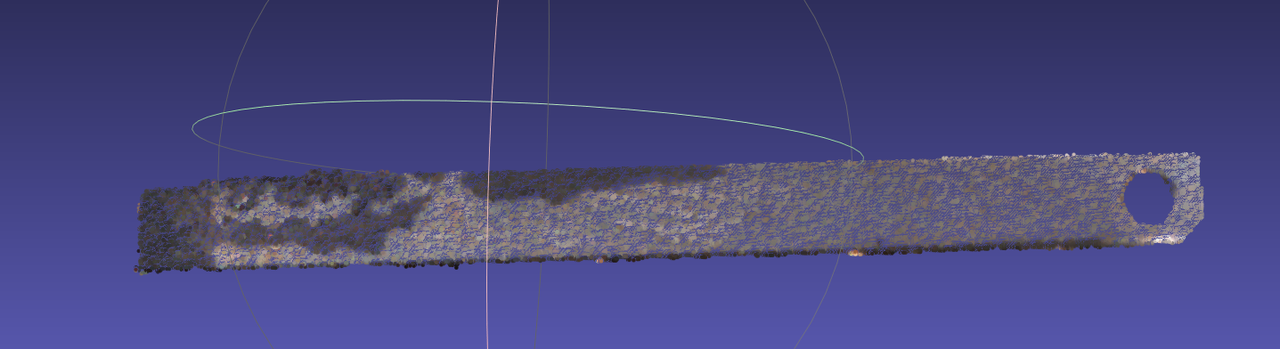
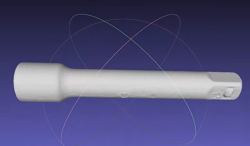
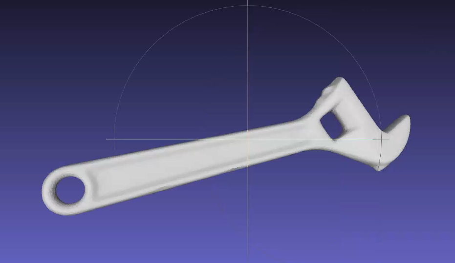
When the Target is a symmetrical Target: Currently, only rotationally symmetrical Targets are supported, that is, the Target completely coincides with itself after being rotated at a certain angle. You can check Symmetrical in the Target Properties;
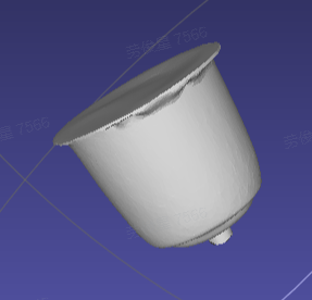
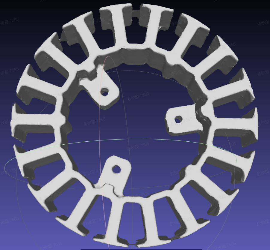
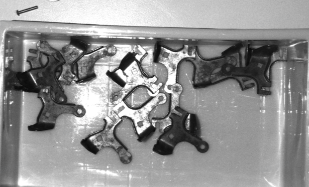
When the Target is a Highly Reflective Target: The surface of the Target is very glossy and prone to highlights and reflections. For example, for metal Targets, you can check the Highly Reflective option in the Target Properties;

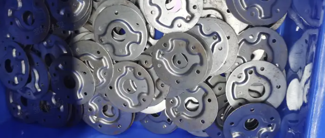
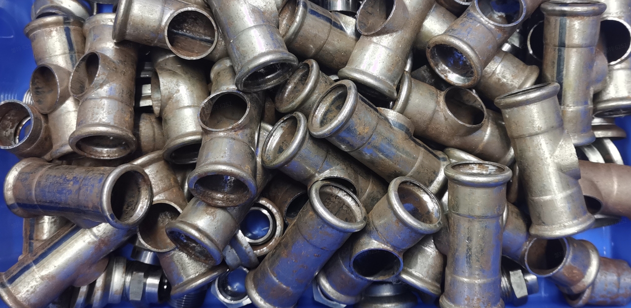
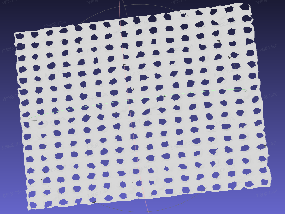
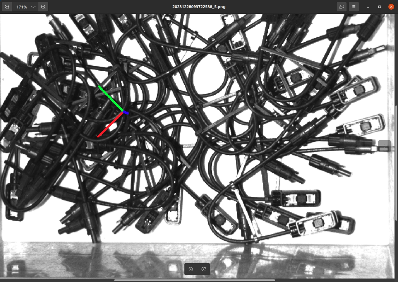
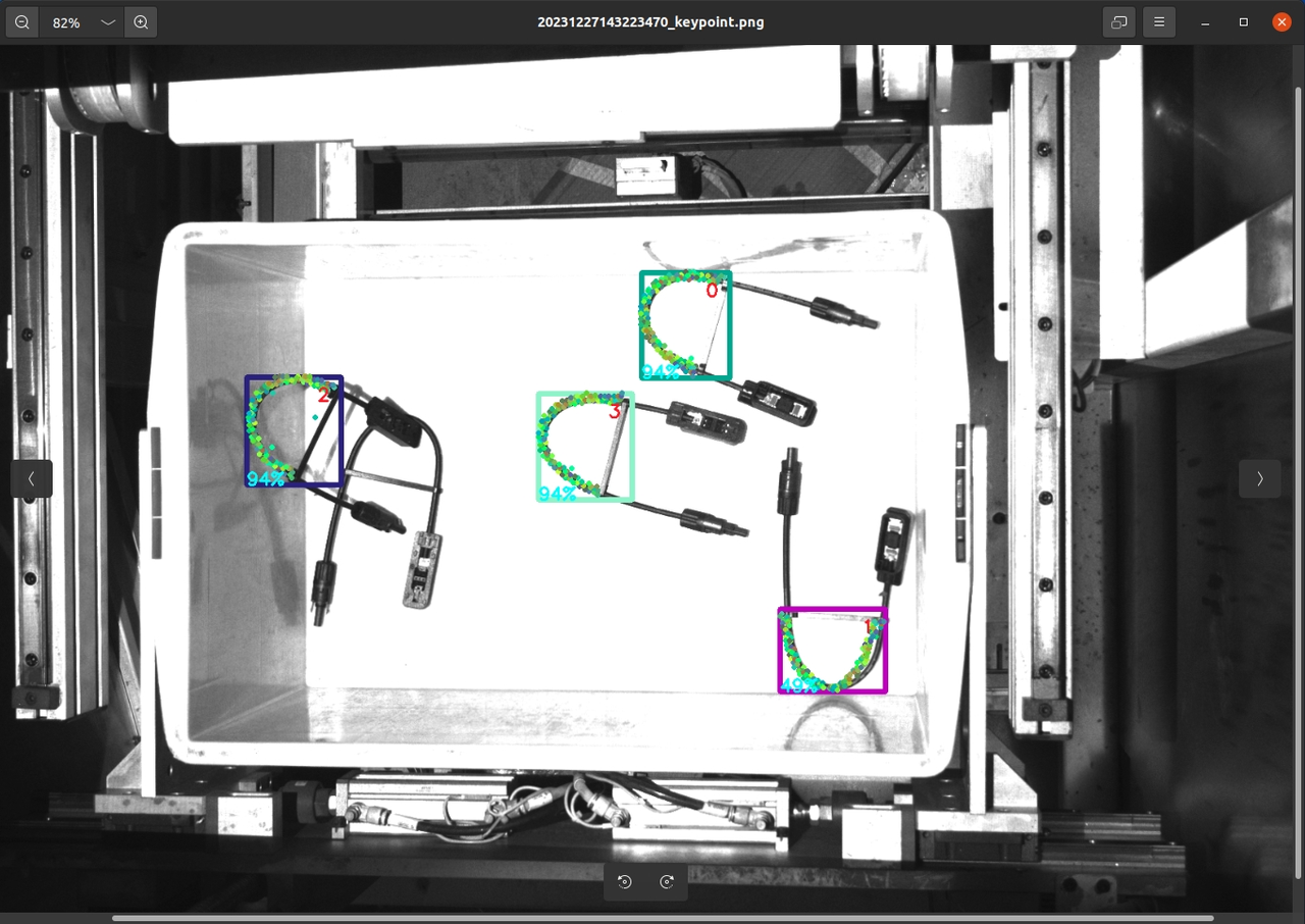
When the Target is a low-density Target: there is a large area of hollowing on the surface of the Target, or the solid part of the Target only accounts for a small part of its surface area, such as a wire harness type Target, you can check Low solidity in the Target Properties.
3.4 Pattern mask
In the general/face-type Target Ordered loading and unloading Scene, when training the Visual Model through one-click connection, you need to enter the Pattern mask to simulate the incoming material method of the Target in the actual Scene. In this way, the trained Visual Model has better recognition effect and higher robustness for the actual Scene.
Pattern masks are divided into two types: "Tight fit" and "Custom Pattern mask". "Tight fit" is suitable for scenes with orderly incoming materials from Target, consistent postures, and small spacing. "Custom Pattern mask" is suitable for all Scenes with orderly incoming materials.
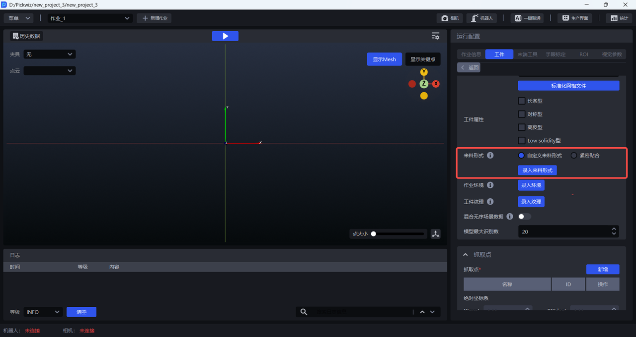
3.4.1 tight fit
If the Targets are delivered in an orderly manner, with consistent postures and small spacing in the Scene, you can click Close Fit to set the number of Targets in each row and column, but the total number of Targets must be less than 40. If the number of Targets exceeds 40, it is necessary to ensure that the set ratio of the number of Targets in rows/columns and the actual ratio of the number of Targets in rows/columns have the same common ratio, such as the actual Pattern of Target. The mask is 12 per row and 8 per column, so the ratio of the number of row/column Targets is 12:8, which can be reduced to the simplest 3:2. Therefore, you can set 3 per row and 2 per column, or 6 per row and 4 per column, but 9 per row and 6 per column are not allowed (more than 40).
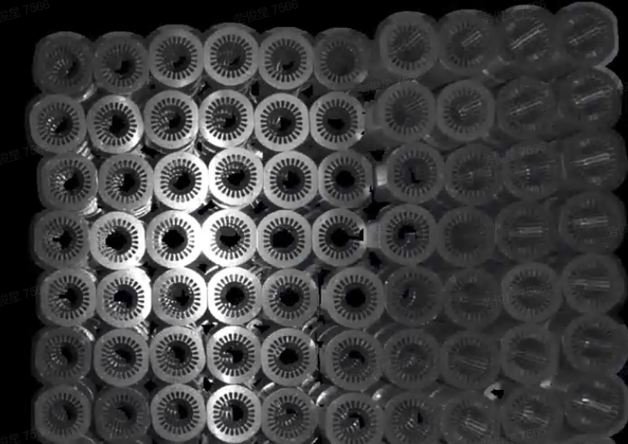
Example:
The Pattern mask of Target is 6 per row and 3 per column, and the number of Targets is 18. Therefore, you can directly set the range of the number of Targets in each row to [6,6], and the range of the number of Targets in each column to [3,3].
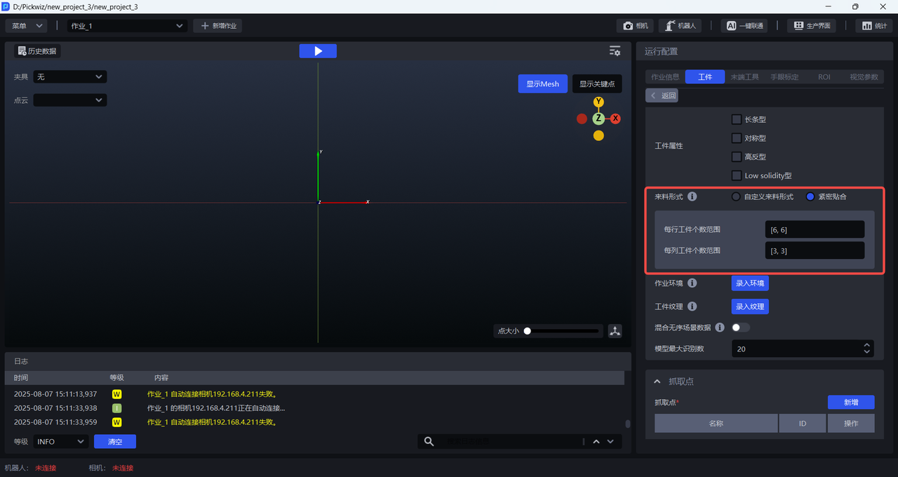
3.4.2 Custom Pattern mask
All Scenes with incoming materials in order can customize the Pattern mask. The operation steps are as follows:
- Click
Enter Pattern maskto open thePattern mask importer
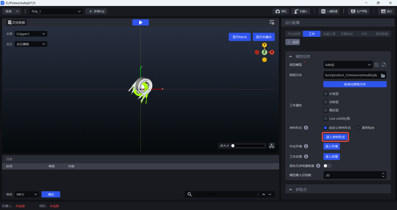
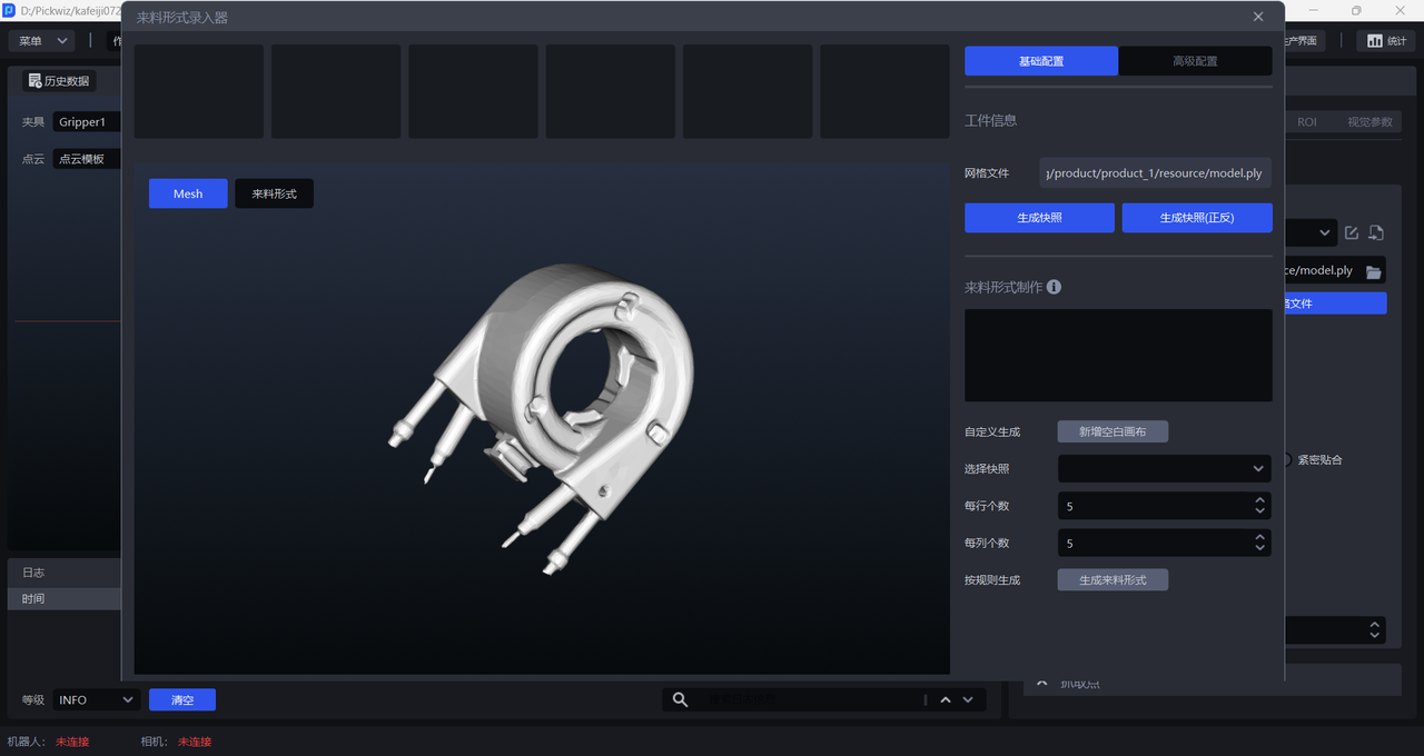
- Rotate the Mesh model to the appropriate posture (Target posture from the camera's perspective), and click
Generate Snapshot/Generate Snapshot (front and back)to generate a Target snapshot in that posture.Generate Snapshot (front and back)will generate snapshots of both the front and back views, as shown below.
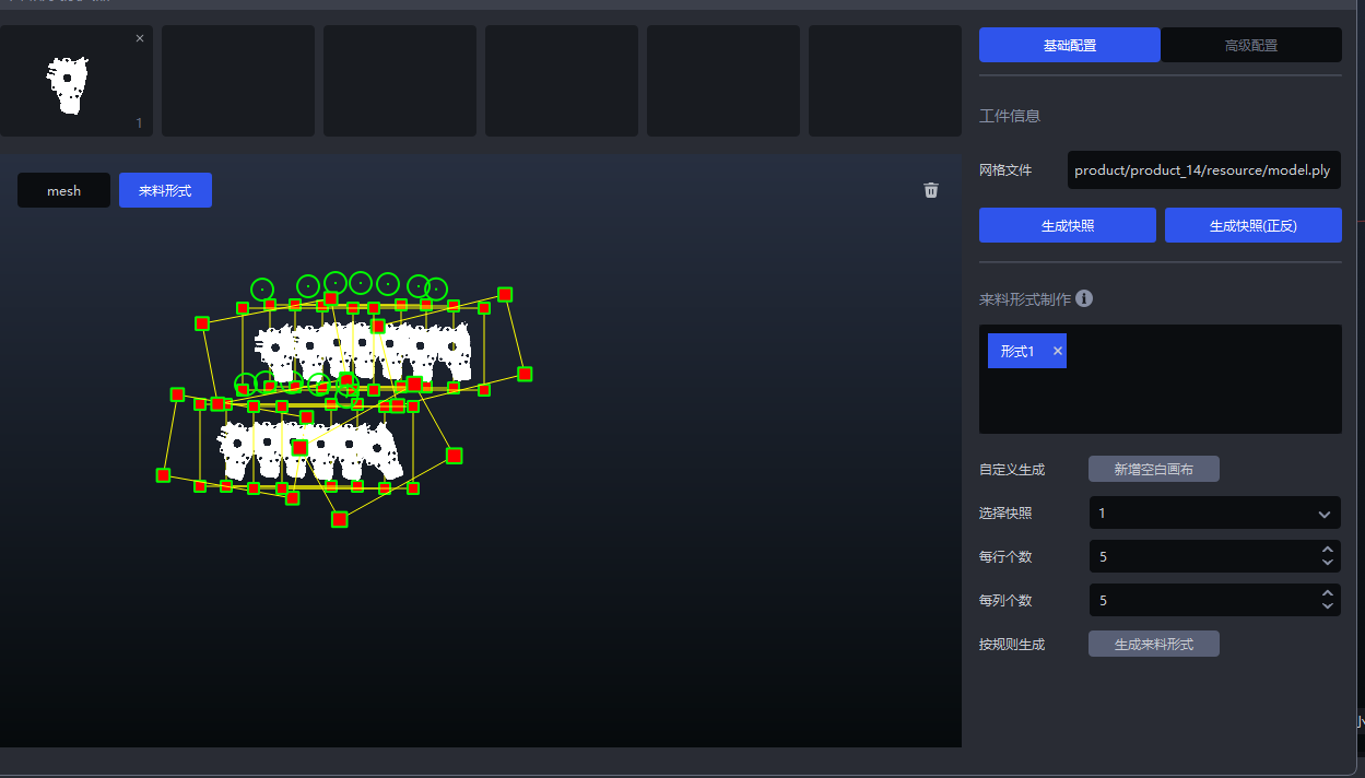
- After generating a snapshot, you can click
Add Blank Canvasand drag the snapshot into the canvas to create the Target's Pattern mask based on the actual Scene, as shown below.
You can also select a snapshot, set the number of each row and each column, and then click Generate Pattern Mask. The system will directly generate the Pattern mask on the canvas according to the selected snapshot and the set number of rows and columns, as shown below.
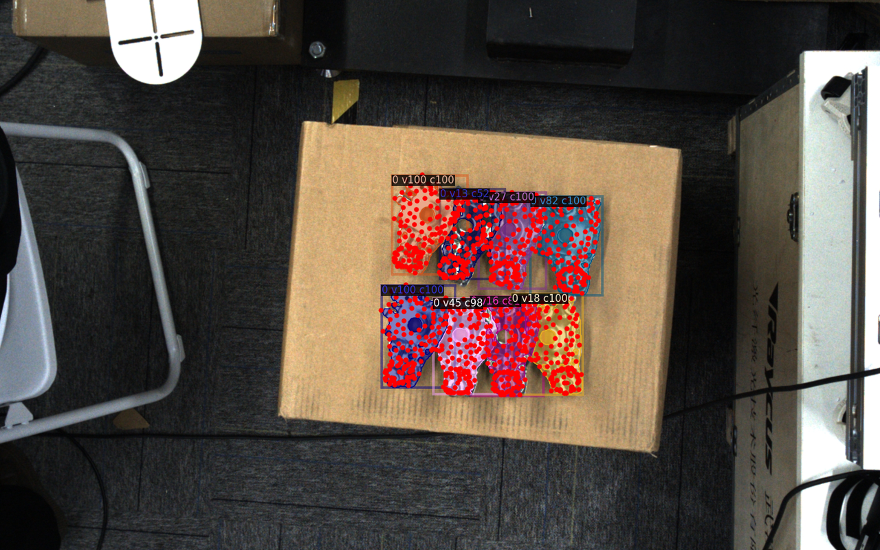
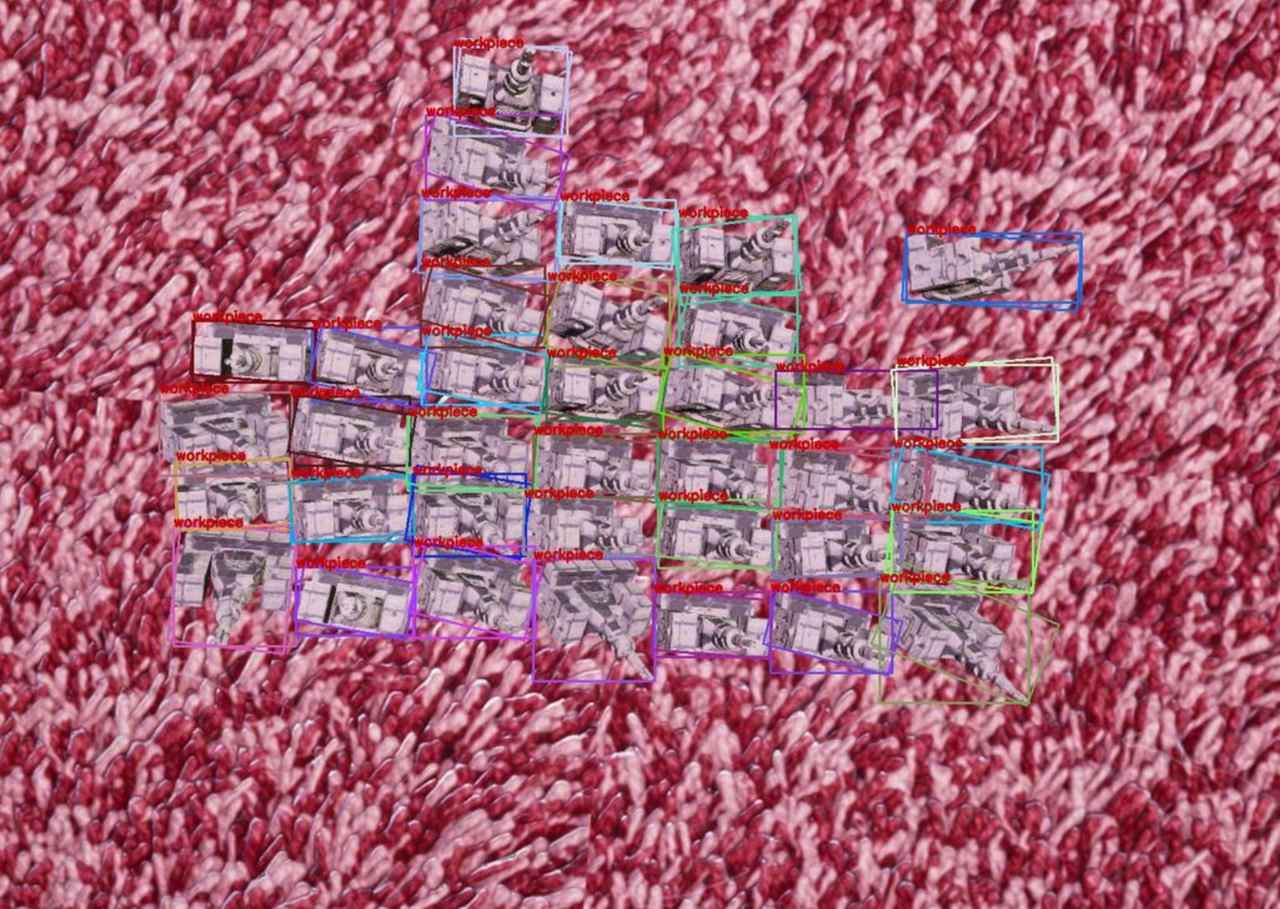
- After entering the Pattern mask, configure the other items one by one. After triggering the one-click connection, the one-click connection training of the ordered scene will generate training data based on the entered Pattern mask, as shown in the figure below.
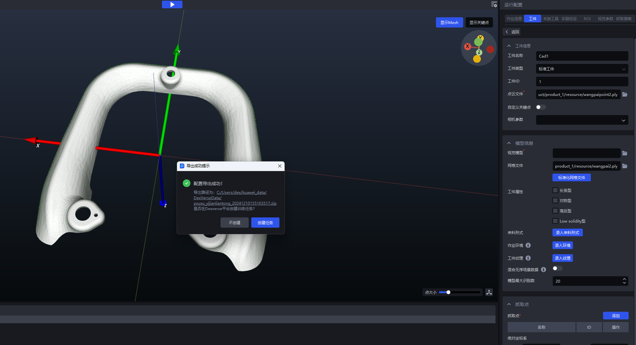
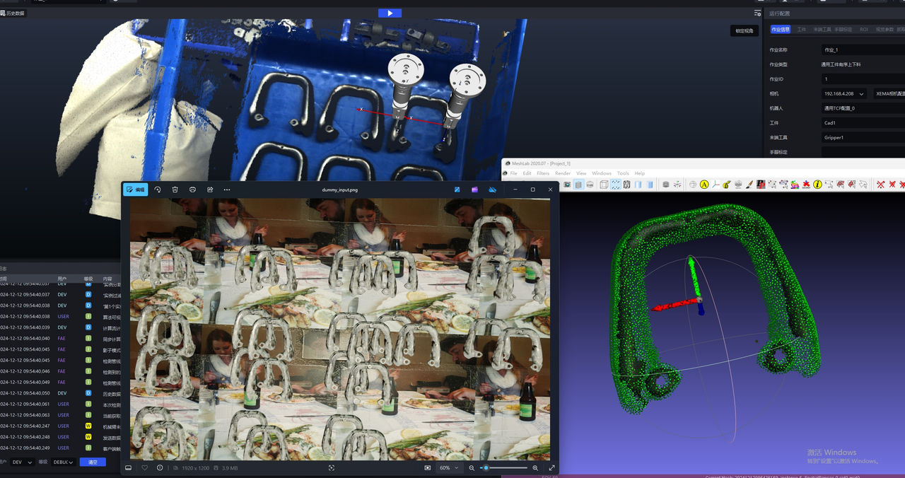
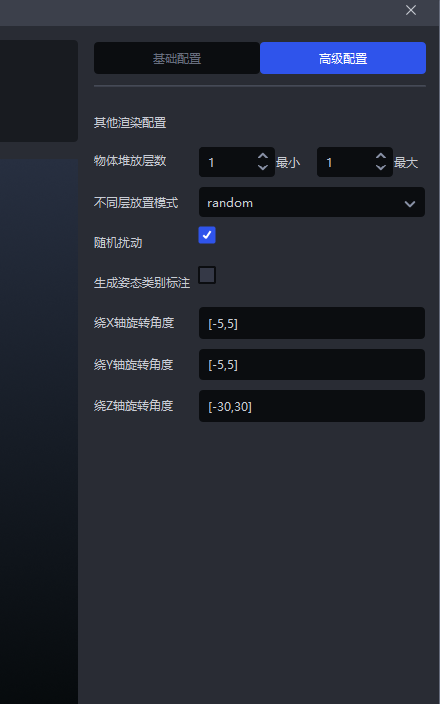
If the Target of the actual Scene is stacked, you need to click
Advanced Configurationto configure the stacking situation, and the rotation angle is set according to the Target posture.
Example: The Target posture in Scene rotates around the Z axis, so set the rotation angle to [-30,30]
  |  |
|---|
3.5 Task environment
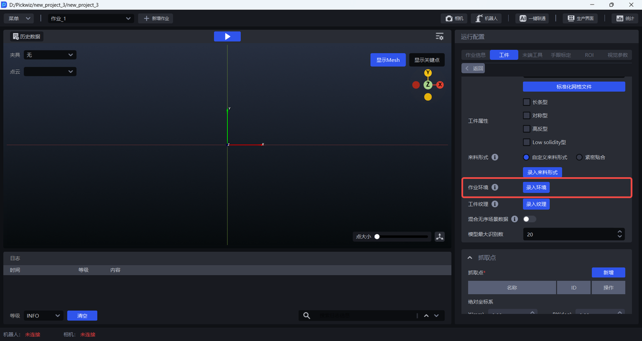
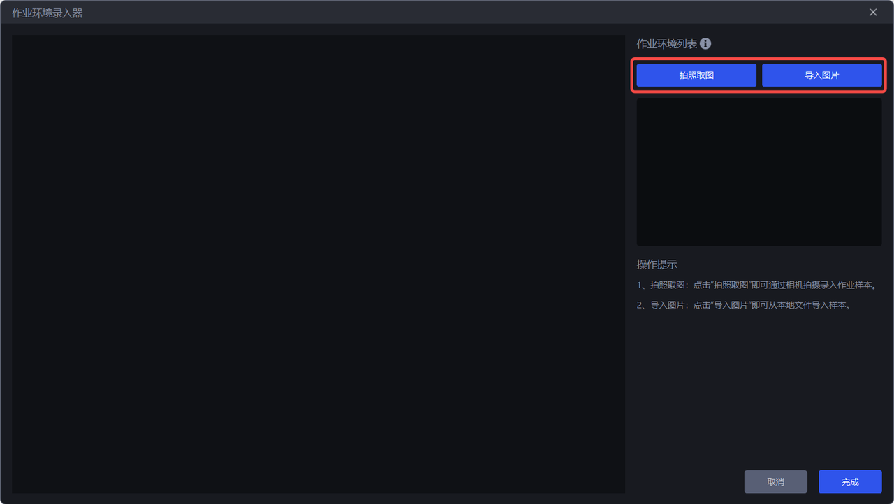
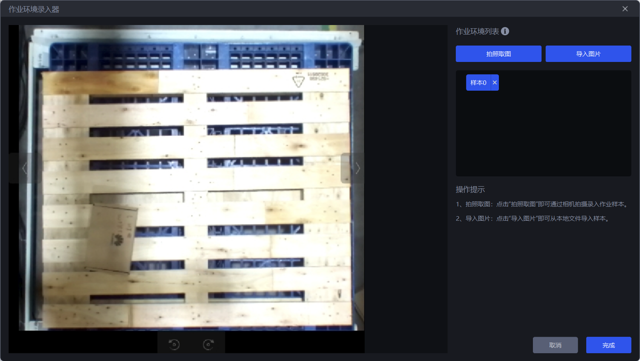
When training the Visual Model with general Target and face-type Target, the Task environment can be entered. When generating training data through one-click connection, the original randomly changing background of the synthetic image will be replaced with the entered Task environment picture. In this way, the trained Visual Model has better recognition effect and higher robustness for actual Scene.
The steps are as follows:
- Click
Enter Environmentto enter theTask Environment Enterer
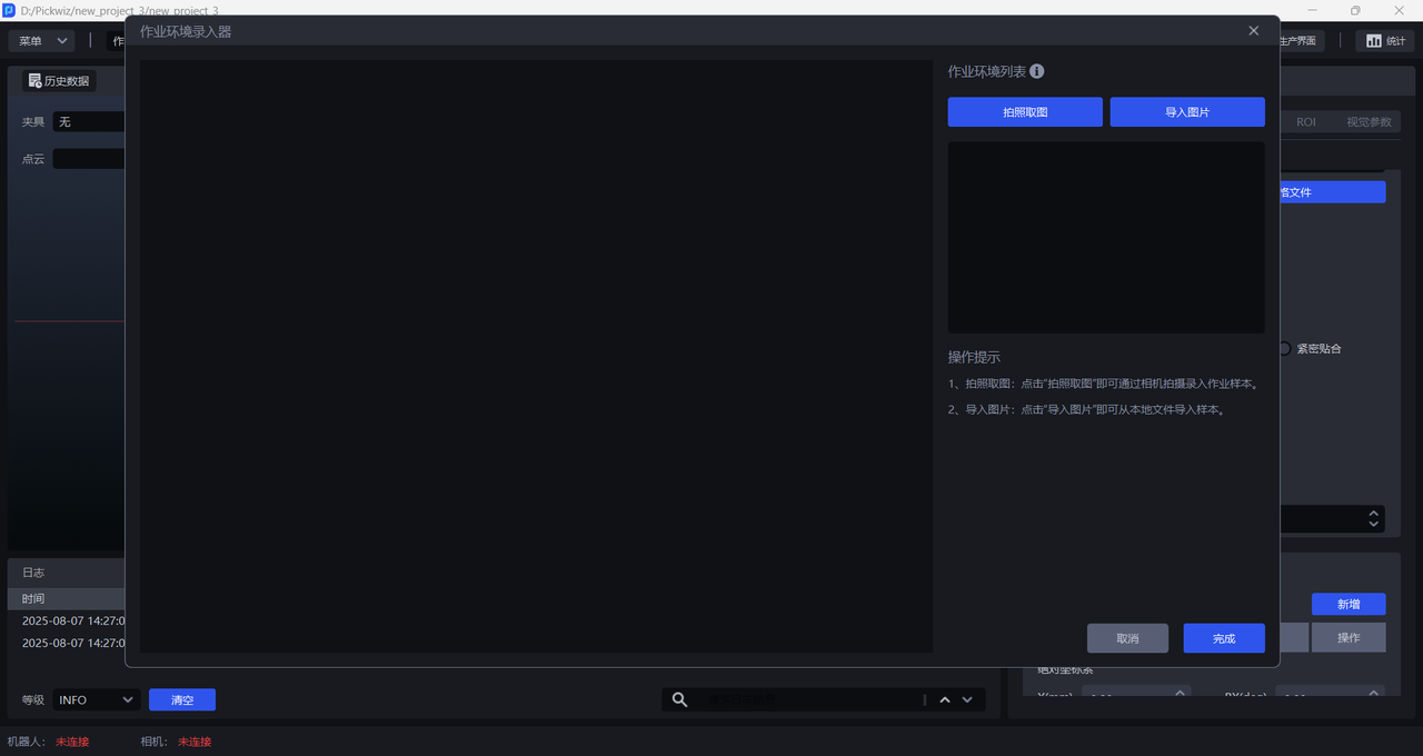
- There are two ways to obtain Task environment pictures: one is to 'take pictures' to collect the Task environment under the camera's field of view, and the other is to directly 'import pictures'. Task environment pictures cannot include Target and material frames, but can include trays and bottom brackets.
3.6 Target texture
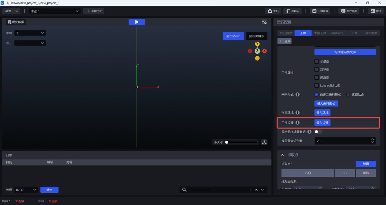
When training a Visual Model with a general/face-type Target, you can enter the Target texture. One-click Unicom will use the uploaded Target texture to generate training data. In this way, the trained Visual Model will have better Target recognition effects and higher robustness.
The steps are as follows:
- Click
Input Textureto enter theTexture Importer
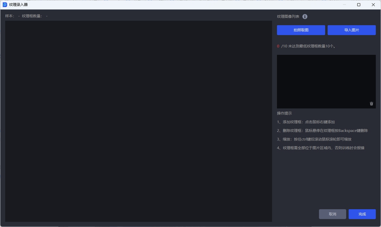
- There are two ways to obtain Target texture pictures: one is to
take pictures' to collect the Target texture under the camera's field of view, and the other is toimport pictures' directly.
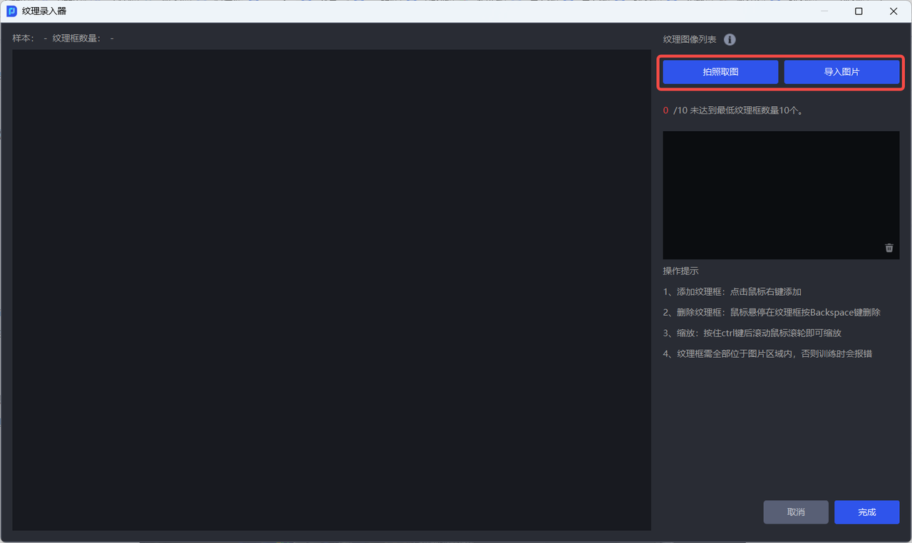
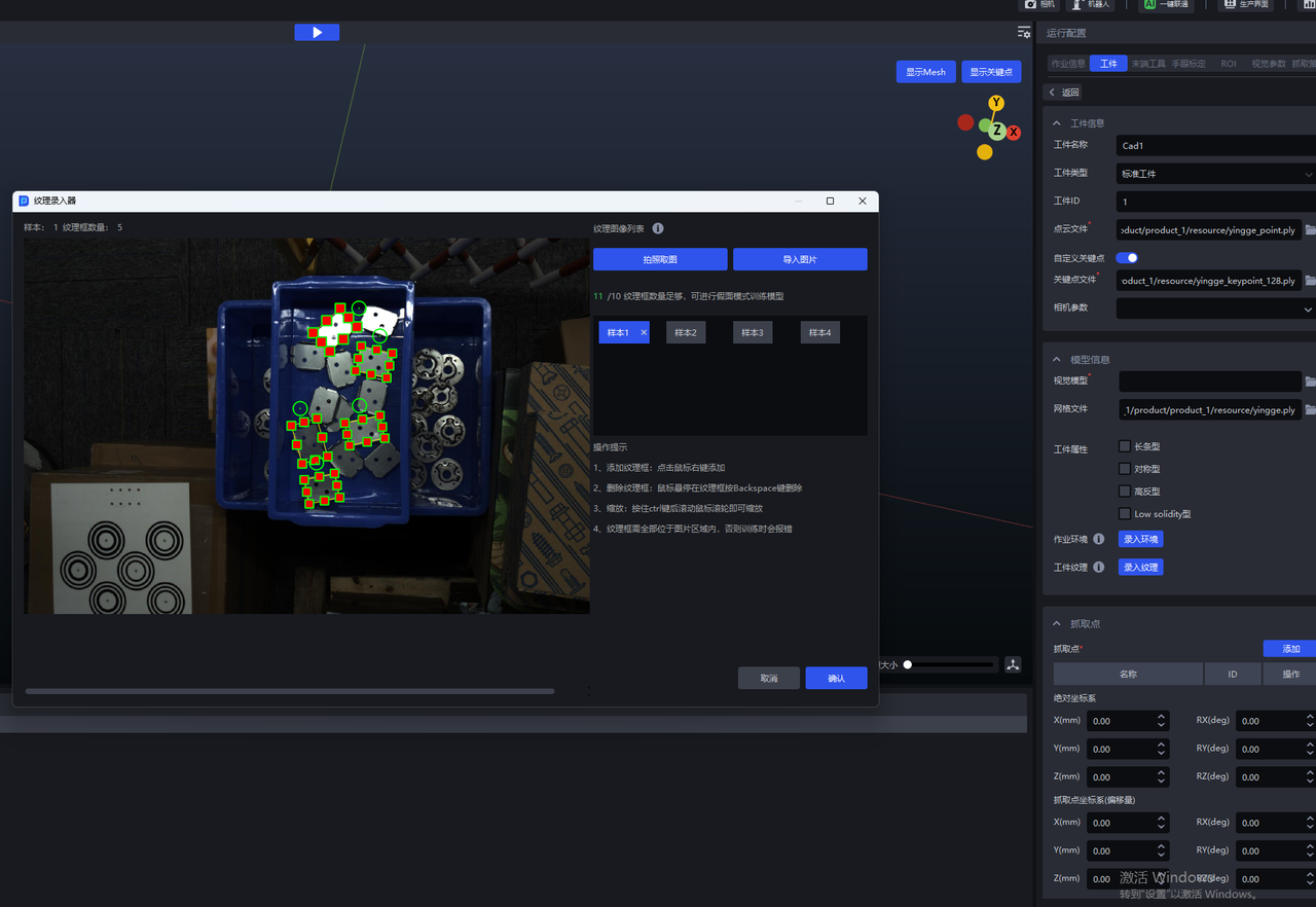
- After obtaining the Target texture image, click the right mouse button to add a texture frame to the image; hold down the
Ctrlkey and slide the mouse wheel to zoom the texture box; hover the mouse over the texture box and press theBackSpacekey to delete the texture box.
Notice:
The texture frame should completely frame the Target and fit the edge of the Target, otherwise it will affect the recognition effect of the Visual Model;
The texture frames should all be located within the image area, otherwise an error will be reported when training the Visual Model.
3.7 mixed unordered Scene data
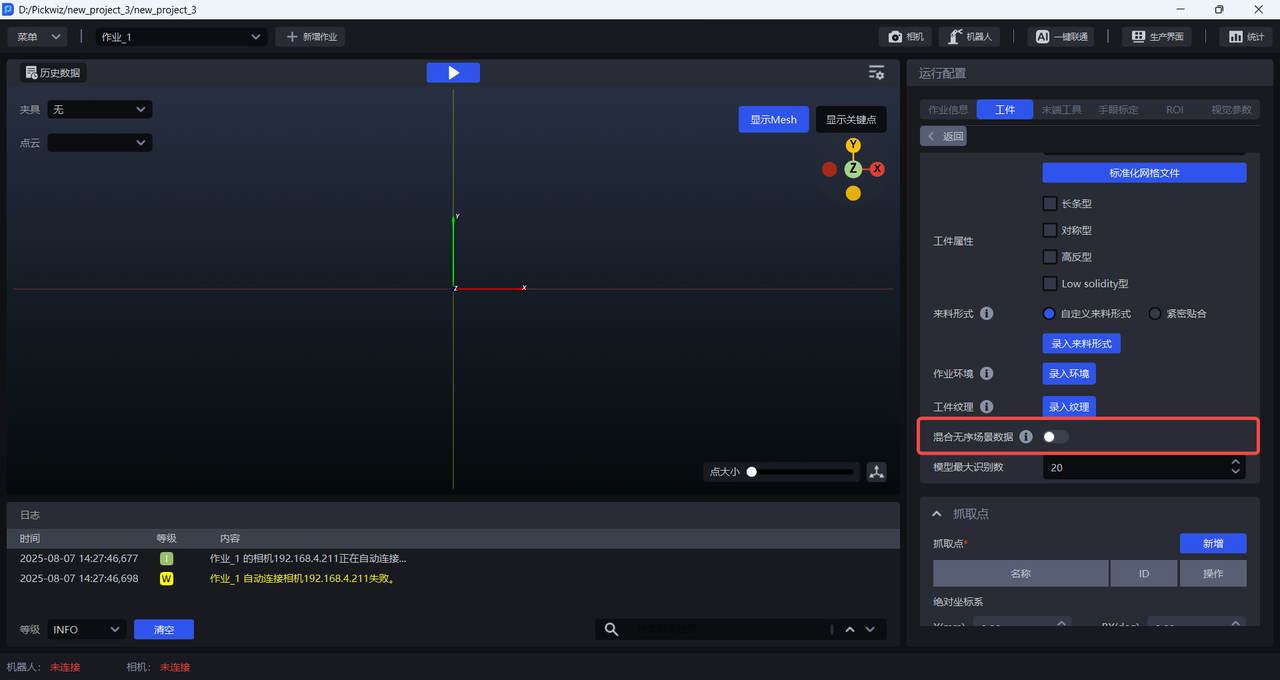
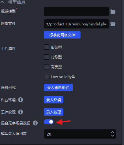
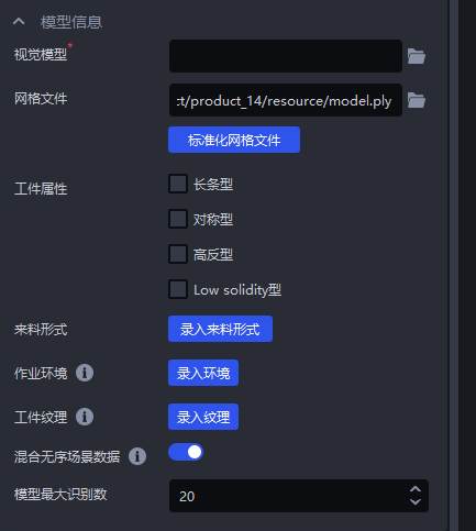
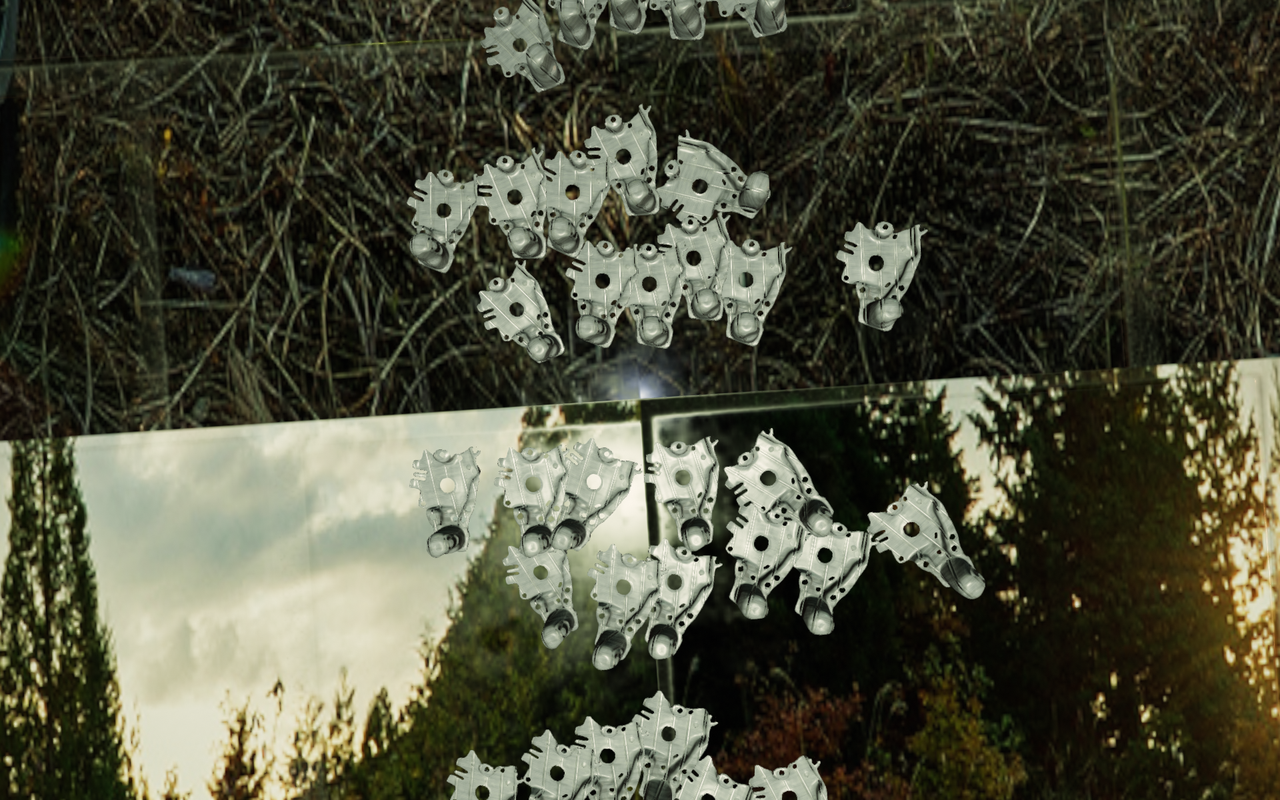
In the universal/face-type Target Ordered loading and unloading Scene, if the Pattern mask of the Target is in order but the Target posture is inconsistent, you can turn on Mixed Unordered Scene Data. One-click connection will simultaneously generate synthetic data for the ordered Scene (the rows and rows are ordered) and the unordered Scene (the posture is inconsistent) for training. In this way, the trained Visual Model has better recognition effect and higher robustness for Scenes with inconsistent Target postures.
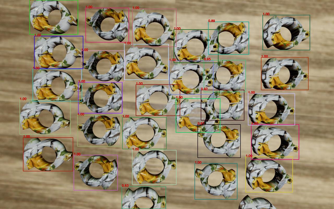
Example: There is little difference between the front and back sides of a facial + symmetrical Target. If you turn on Mixed Unordered Scene Data, the generated training data contains multiple postures, and the model will make errors in judging the front and back sides of the Target, as shown in the figure below.
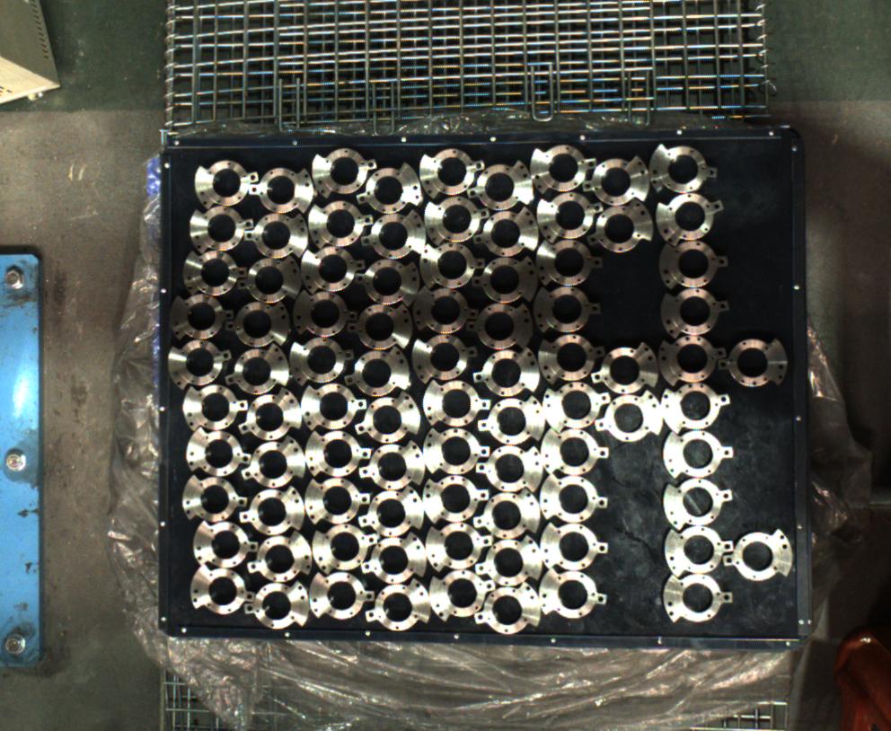
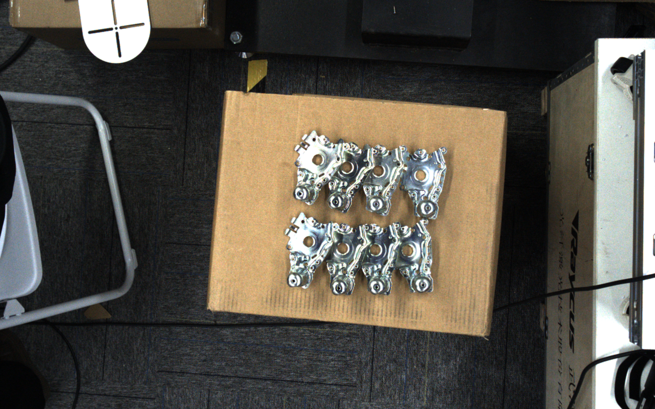
Example: In Loading and unloading of neatly arranged general type target objects Scene, turn on Mixed Unordered Scene Data, and trigger one-click connection. The synthesized image generated contains both the orderly rows and columns of the ordered Scene, and the inconsistent postures of the disordered Scene.
3.8 model maximum recognition number
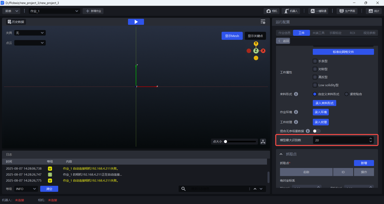
The maximum number of recognitions of the model refers to the maximum number of instance detection results that the model can output when inference on a single image. Limiting the maximum number of recognitions of the model is mainly used to optimize the computing resources in the model inference phase, reduce time consuming and increase cycle time. The default is 20, which can be modified according to the actual number of Targets in the Scene.
3.9 Function Options
When training the Visual Model with universal Target and face-type Target, check the corresponding function options and trigger the one-click connection. The training data generated includes different Target types, different Target orientations, textures, local features, etc. The Visual Model trained in this way has a better recognition effect on actual Scene changes.
3.9.1 Visual Classification
Visual classification refers to classifying Targets according to orientation, texture, etc.
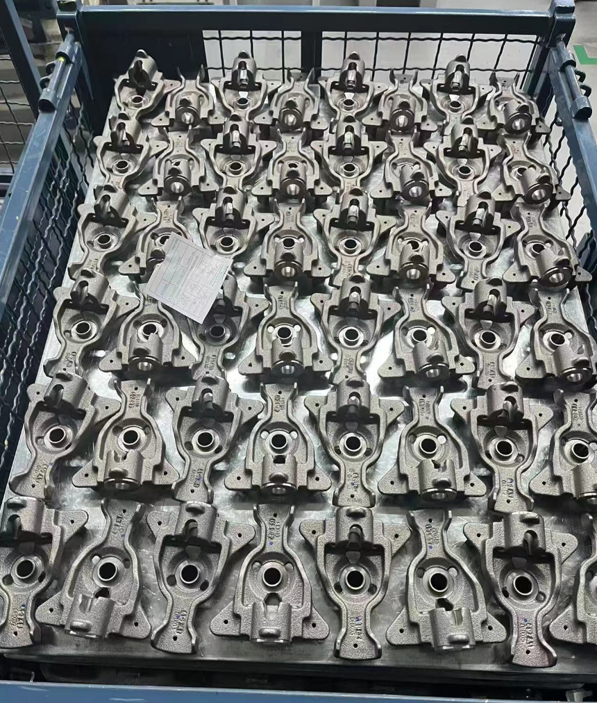
Example: There are two ways to place Targets. You need to grab the Target in the same direction first, and then grab the Target in the opposite direction. After checking the visual classification, you can connect the trained Visual Model with one click to classify the orientation of the target, thereby realizing grabbing by orientation.
3.9.2 Type Identification
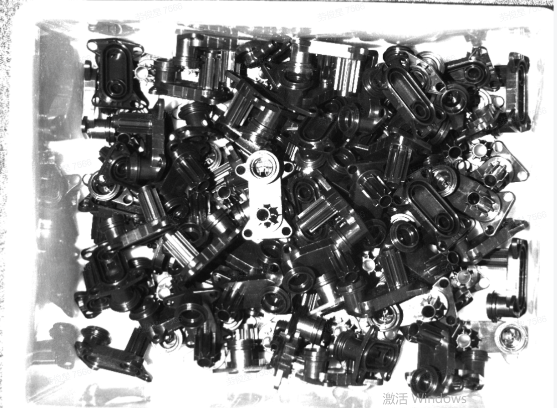
Type Identification refers to the distinction between different categories of Target. The training data generated by One-Click Connect is classified according to preset categories, and the image data of various Targets are input. After the model is learned, it can determine the category to which the Target belongs.
The front and back sides of Target can be regarded as two types, and the Type Identification function can be used to generate two types of training data including the front and back sides. When using Type Identification to train the front and back sides, you need to upload the Point Cloud of the front and back sides of Target.
Example: Target has a complex structure and large changes in characteristics at different angles. Therefore, when making a Target Point Cloud, both the front and back Point Clouds need to be made, and the front and back Point Clouds are synthesized into a PCD (Point Cloud Data).
3.9.3 Local Identification
Local Identification refers to the identification of Target’s local features (such as holes, bumps, etc.).
Picking of randomly arranged plane type target objectsScene does not currently support Local Identification
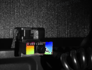
Example: When there is only one Target in the camera's field of view, it can be converted into an ordered Scene to use one-click connection. It is necessary to use overall CAD to simulate the effect of blocking the recognition surface.
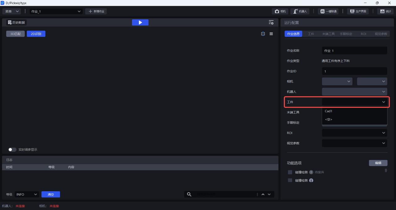
After completing the Target configuration, select the new Target configuration in the Task information.
3.10 Camera height range from Target
In a Scene that supports one-click connection, the height range of the Target module's Camera from the Target can be specified according to the actual Scene conditions. The rendering height of one-click connection can be specified.
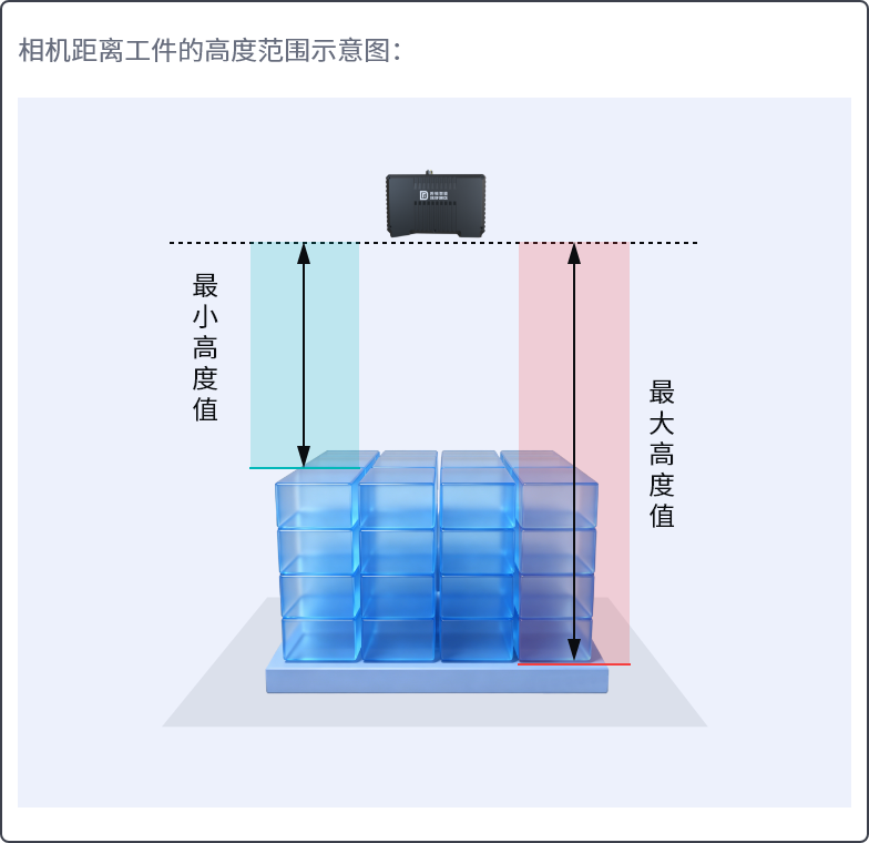
The Target rendering height of One-Click Connect refers to the ROI or the height range. If the ROI and the Parameter are uploaded at the same time, the rendering height shall be based on the Parameter.
4. Configure ROI
When initiating one-click connection to train the Imaging Model, the height range between the ROI and the Camera from the Target only needs to meet one of them. If the ROI and the Parameter are uploaded at the same time, the rendering height will be based on the height range between the Camera and the Target.
When configuring ROI, please refer to ROI Operation Guide to configure ROI 3D and ROI 2D in the ROI interface.
Notice:
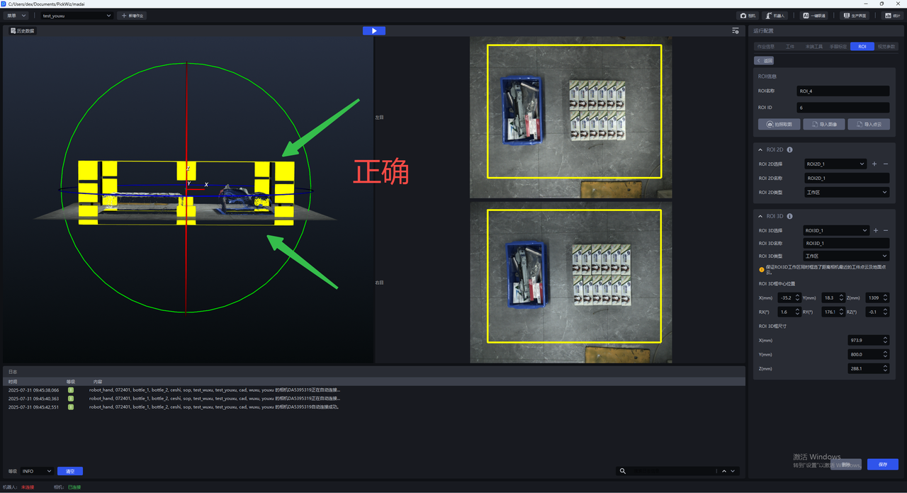
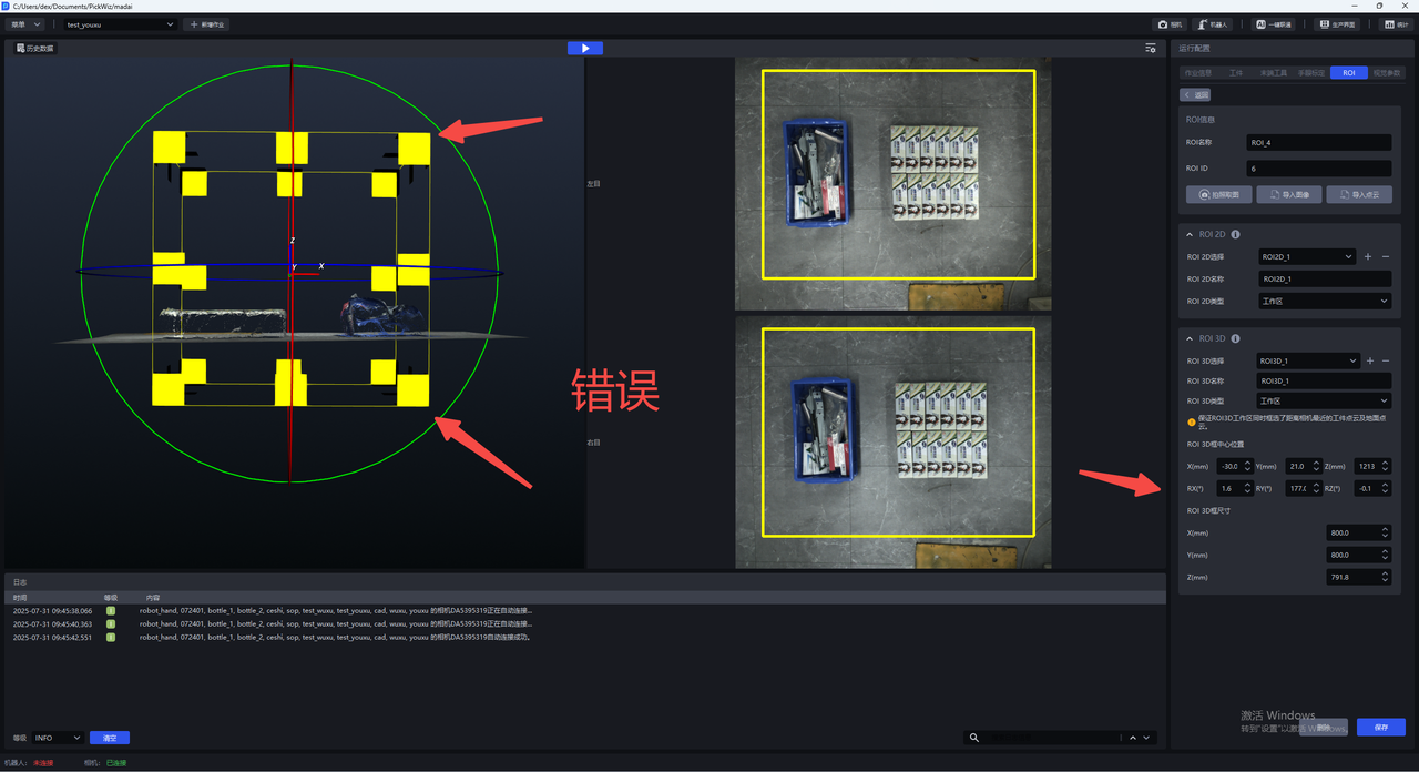
When adjusting ROI 3D, ensure that the Z-direction height of the ROI 3D** workspace** just includes the TargetPoint Cloud and ground Point Cloud closest to the Camera (as shown below).
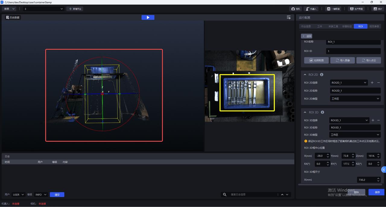
The bottom edge of the ROI 3D frame should be as close to the ground as possible, and the top surface should not be too high.
5. Configure Scene Object
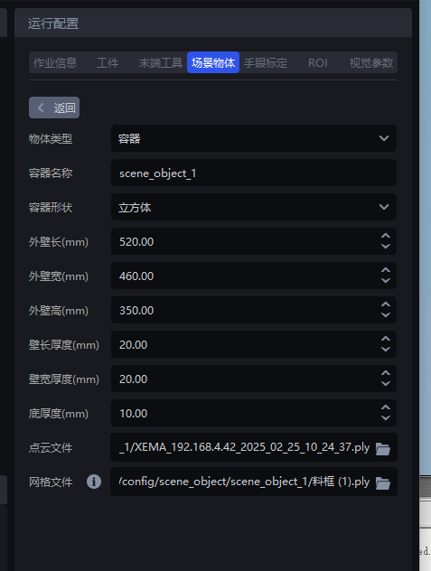
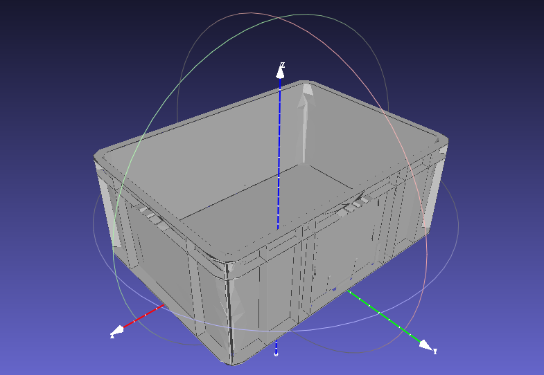
Under the general unordered Scene, for a Scene with a material frame and using the collision detection function option, the Scene Object should be configured and the grid file of the material frame should be uploaded. The Scene Object size must be consistent with the actual material frame size.
6. Create training tasks
After completing the configuration of Camera, Target and ROI, click One-click Connection to trigger the training of Imaging Model.
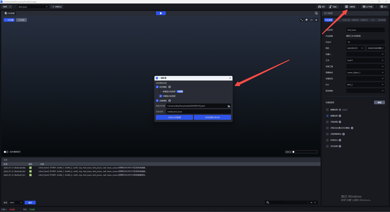
If you need to manually edit the input data, you should select Export training configuration only; if you do not need to edit the input data, you should select Automatically create training tasks.
6.1 Export training configuration only
It is suitable for users who need to manually edit data. Later, they need to manually create training tasks on the DexVerse platform.
- Click
One-click Connectivityon the main interface, and theOne-click Connectivitypop-up window will appear. CheckImaging Model, as shown in the figure below.
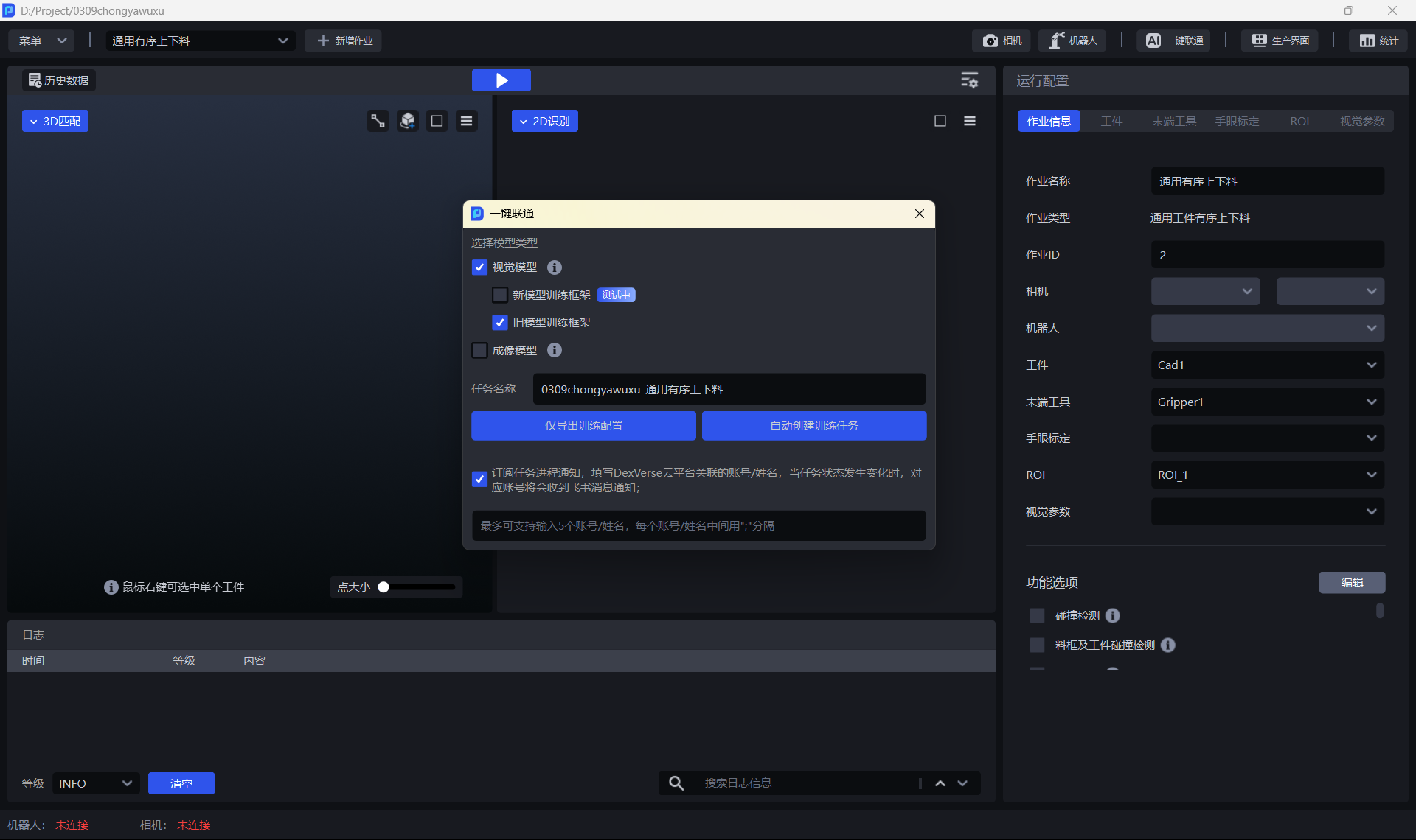
Click
Export training configuration only, you can click the link below the pop-up window to view the contents of the data compression package, or make configuration modifications.Go to the Dexverse platform to create a training task. For specific steps, see DexVerse Operation Manual.
6.2 automatically creates training tasks
Applicable to most Scenes, after PickWiz is configured for Target/ROI, etc., training tasks can be automatically created on the DexVerse platform.
Click
One-Click Connecton the main interface, and theOne-Click Connectpop-up window will appear, as shown in the figure below.Check
Imaging Modeland give the training task a name to make it easier for DexVerse to search for the training task. ClickAutomatically create training tasks.Go to the DexVerse platform to view the automatically created training tasks. For details, please refer to the [DexVerse Operation Manual] (DexVerse操作手册.md).
Subscribe to task progress notifications and fill in the account/name associated with the DexVerse cloud platform. When the task status changes, the corresponding account will receive a Feishu notification.
7. Train Visual Model and Imaging Model at the same time
In the one-click connection pop-up window of PickWiz, you can check Visual Model and Imaging Model at the same time and click Export training configuration only/Automatically create training task.