Camera Issues and Solutions
1. Camera Parameter Adjustment Issues
1. XEMA-LC, High Reflectivity Workpiece, On-site Point Cloud Missing
Solution: For high reflectivity workpieces, use HDR mode with large/small exposure to balance overexposed and underexposed areas. Use radius filtering and depth filtering to reduce noise.
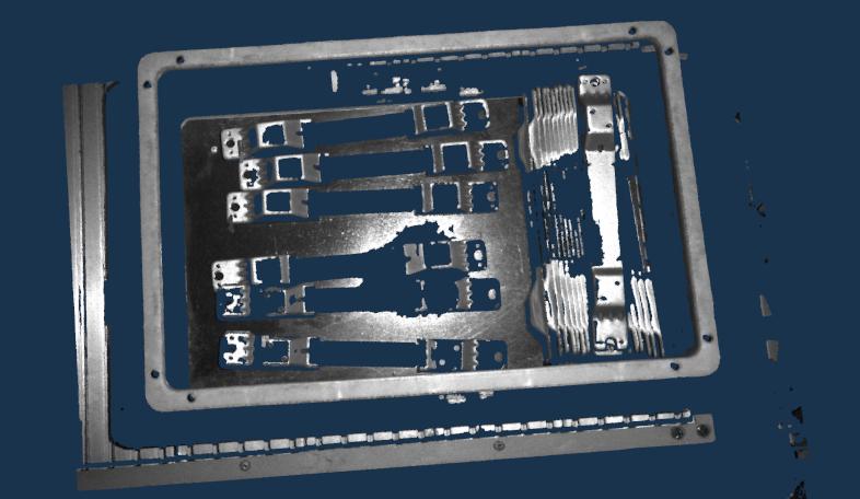
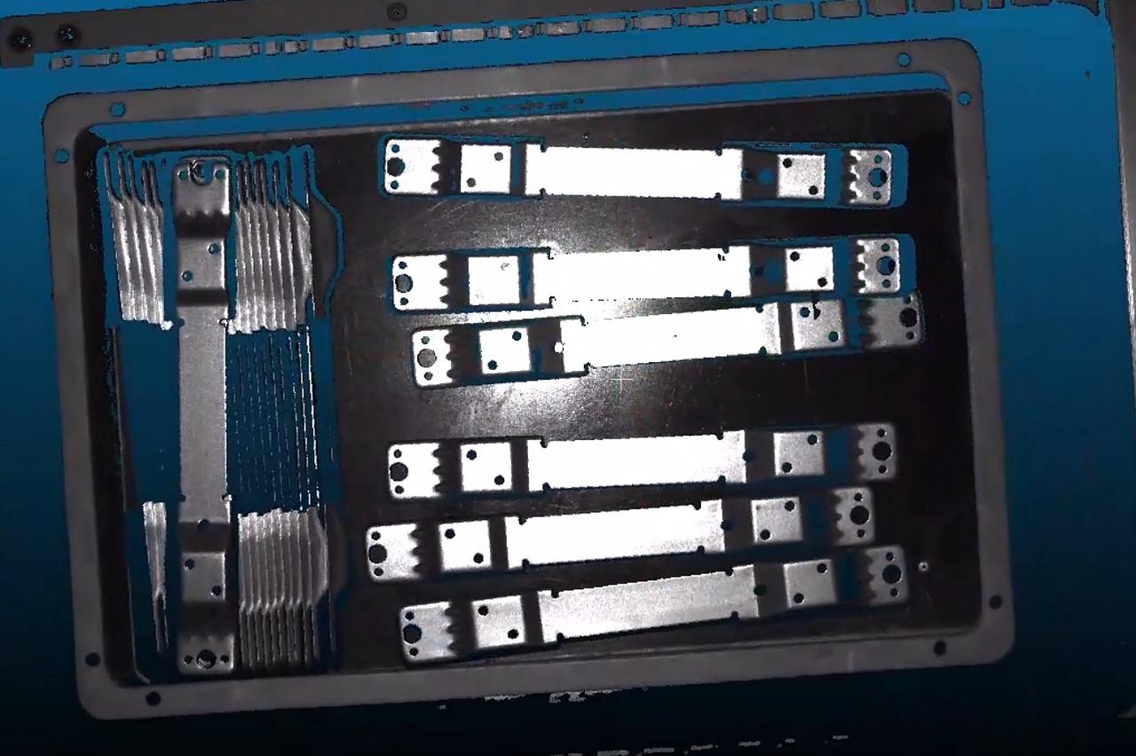
2. XEMA-S, Noise Inside Metal Ring, Large Fluctuations on Ring Edges
Solution: For high reflectivity workpieces, use high dynamic mode in high reflectivity mode. Ensure both parameter sets balance bright and dark areas. Avoid overexposure in the corresponding point cloud as it will affect quality. Enable filtering - if the filter value is too small, increase it for better results. Enable smoothing to reduce point cloud thickness.
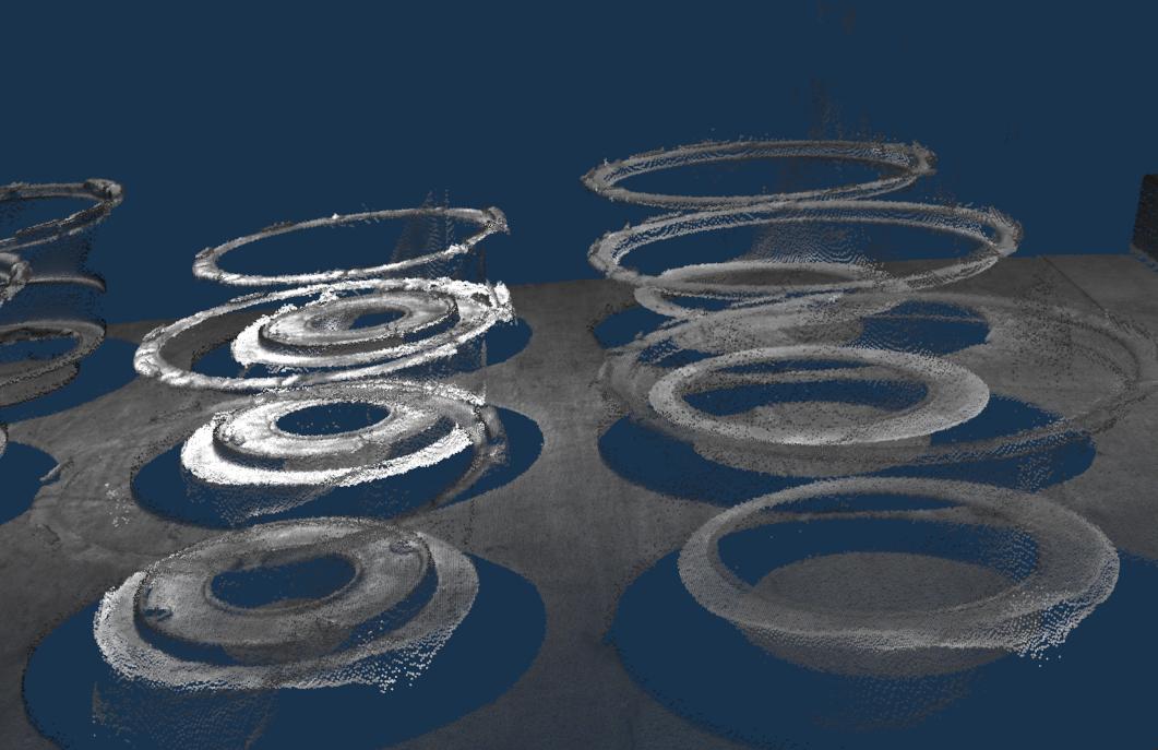
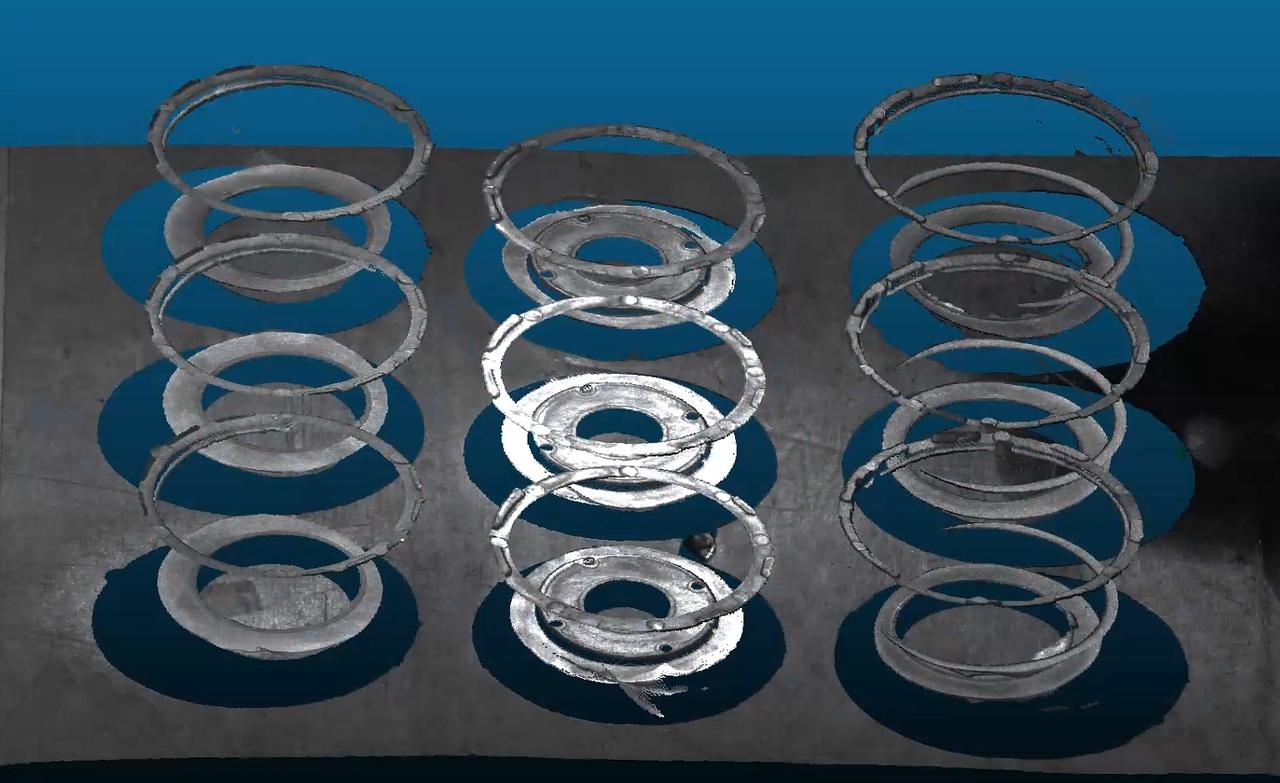
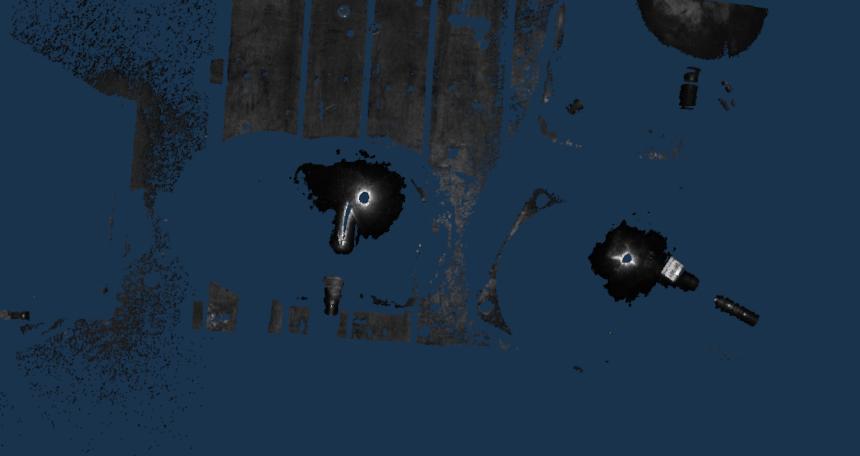
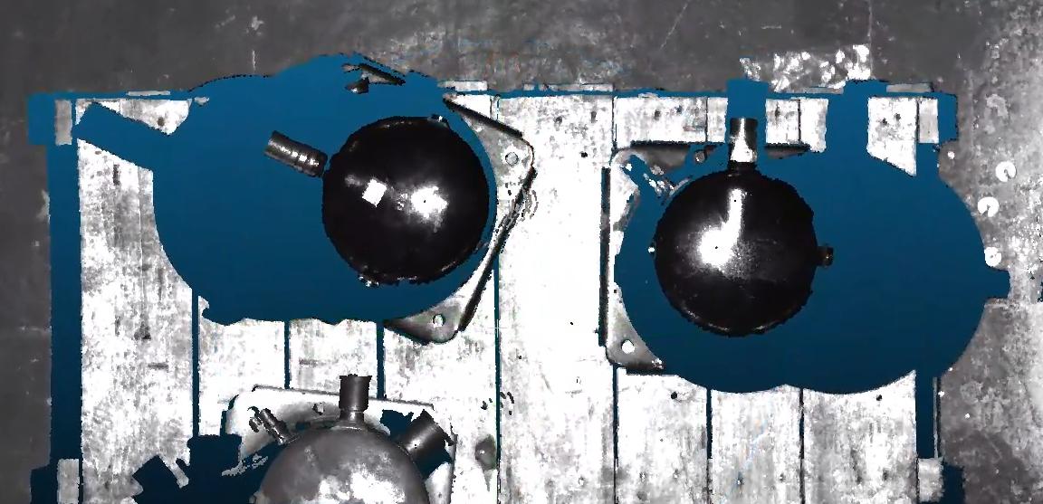
3. XEMA-L, Black Reflective Compressor, Incomplete Point Cloud
Solution: For black highly reflective workpieces, use high dynamic mode with large exposure + gain (to save time). Use radius filtering and reflection filtering for noise reduction.
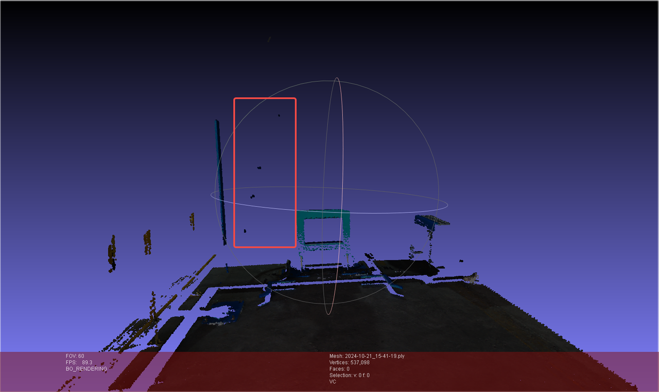
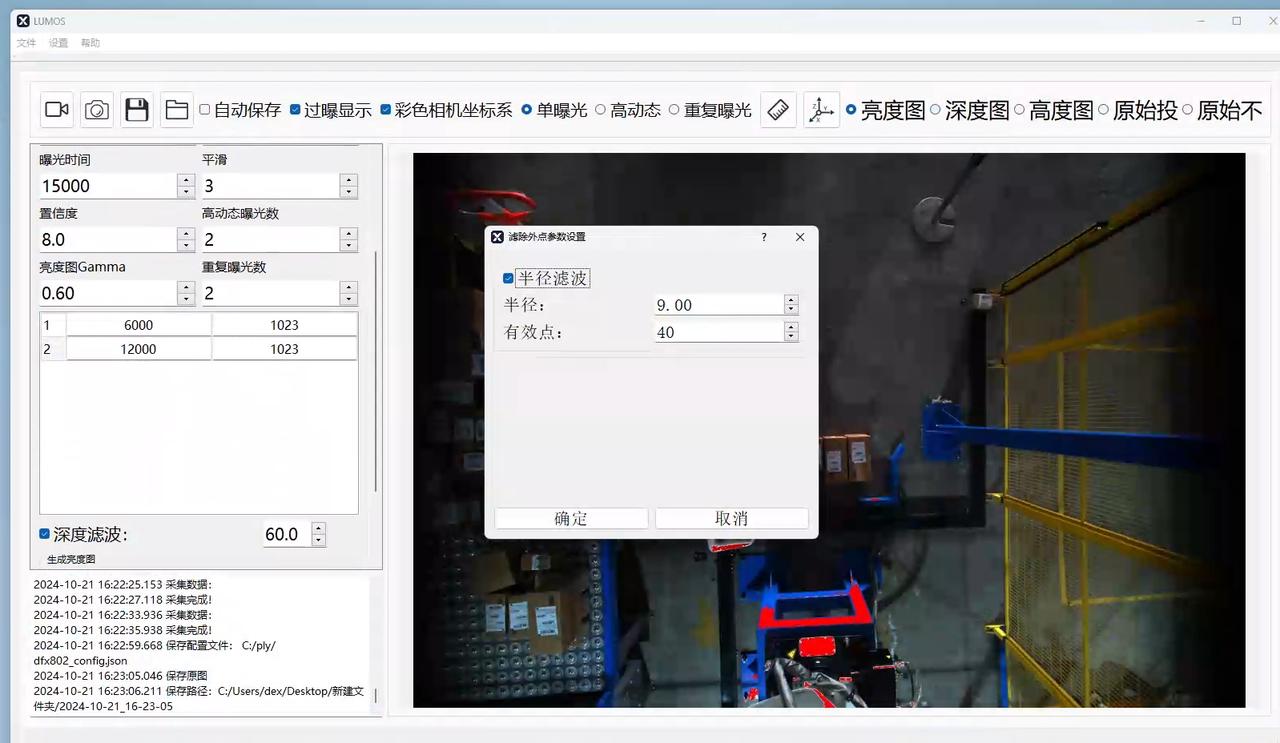
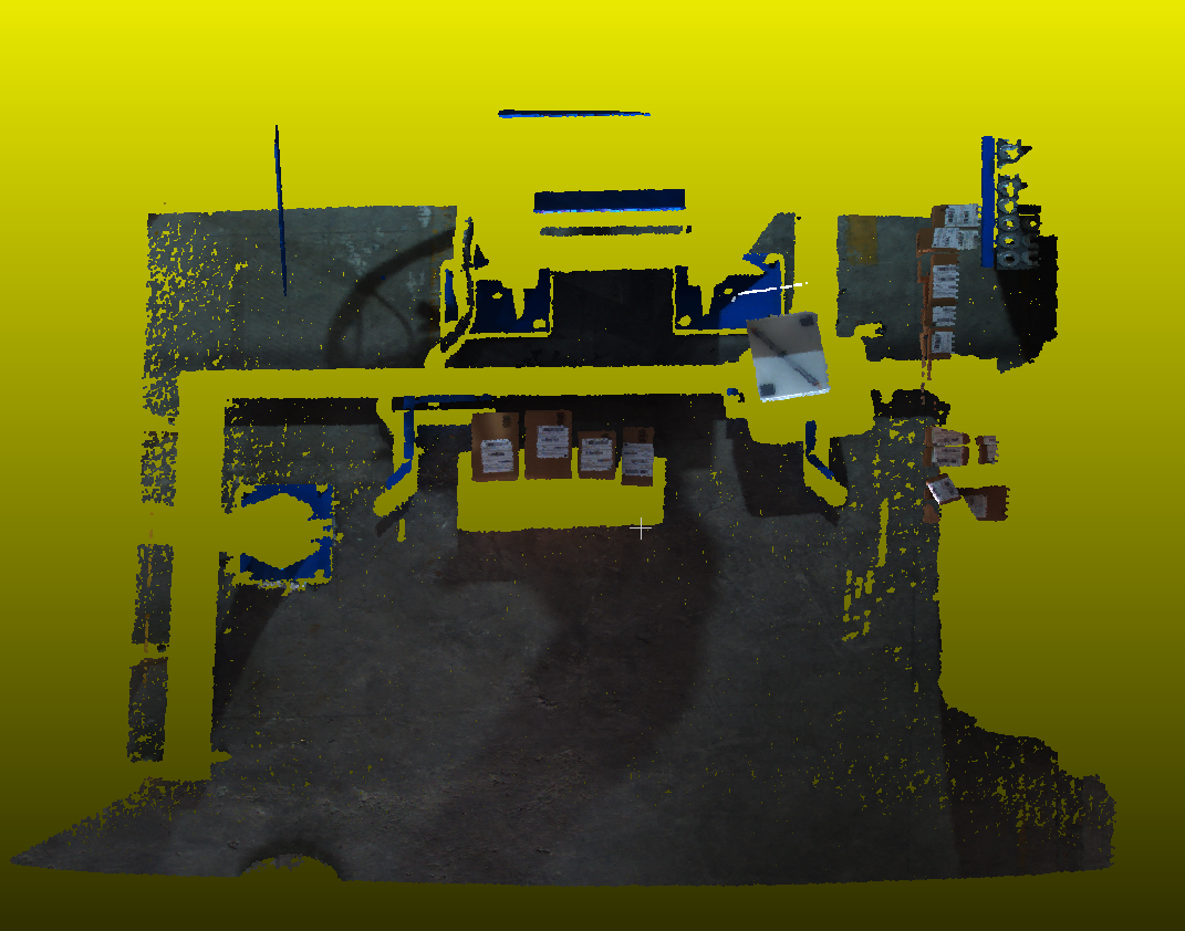
4. FINCH, Noise on Carton Surface
Solution: Enable depth filtering and radius filtering. Larger depth filter values provide stronger filtering. For radius filtering (e.g., fixed radius), larger threshold point counts increase filtering strength. In the example, depth filter 60 is insufficient - increase it while ensuring valid information is preserved. Similarly, increase the threshold point count for radius filtering.
5. XEMA-L, Aluminum Ring, Poor Point Cloud Imaging
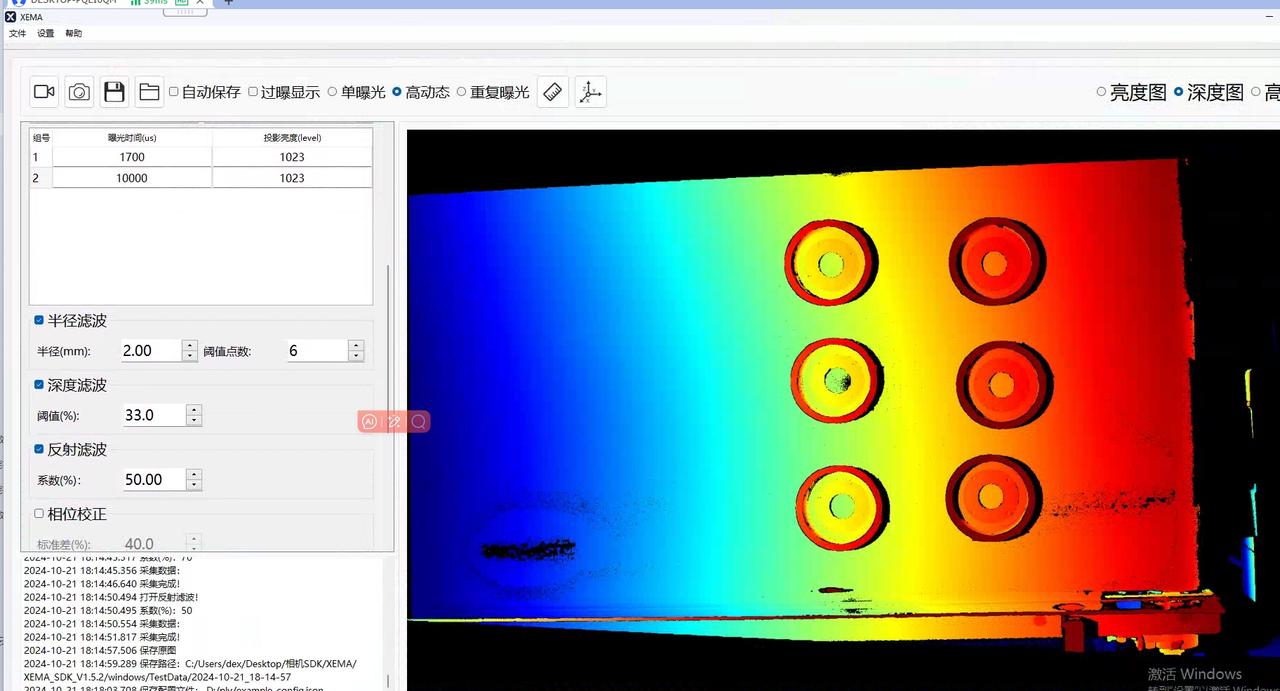
Solution: Use high dynamic mode with two exposure sets: small exposure 1700/1023 to prevent overexposure in bright areas while preserving depth information, and large exposure 10000/1023 to reveal details in dark areas. Use radius filtering and depth filtering for noise reduction. Click high dynamic effect/parameters as shown below.
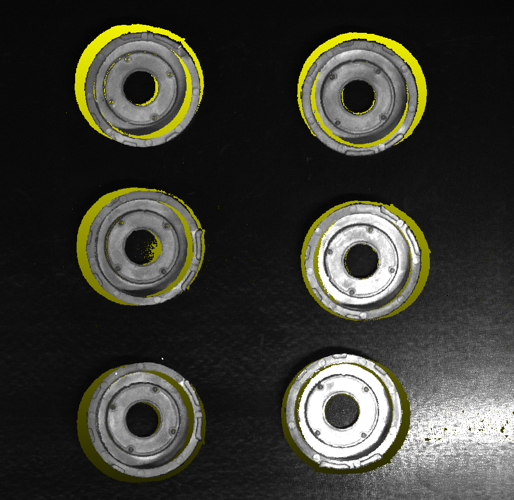
6. XEMA-L, Boxed Circuit Board, Excessive Noise and Point Cloud Missing
Solution: Use small exposure to balance bright areas (avoid overexposure) and large exposure to cover dark areas. For noise, use depth filter 40 with radius filter 2/10 combination. Optimization often requires multiple iterations - adjust parameters while observing depth map and point cloud. Increase depth filter threshold if needed (don't hesitate to increase by more than 1 at a time). Increase radius filter threshold significantly for better results.
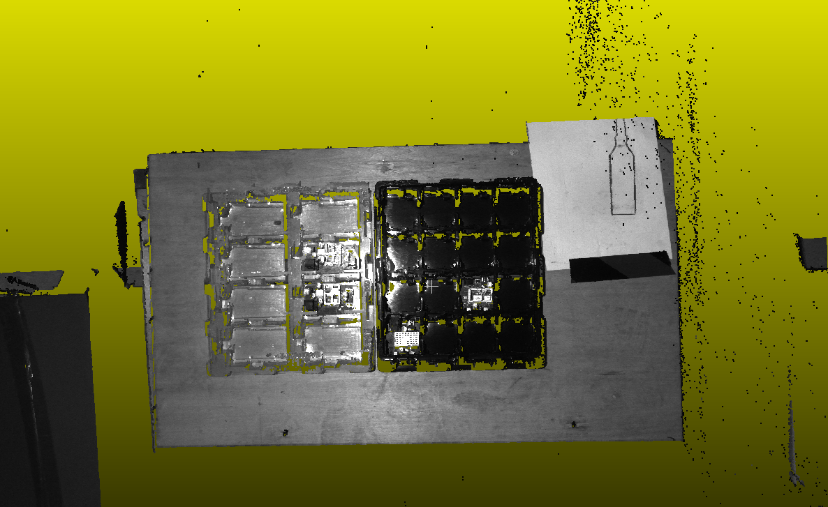
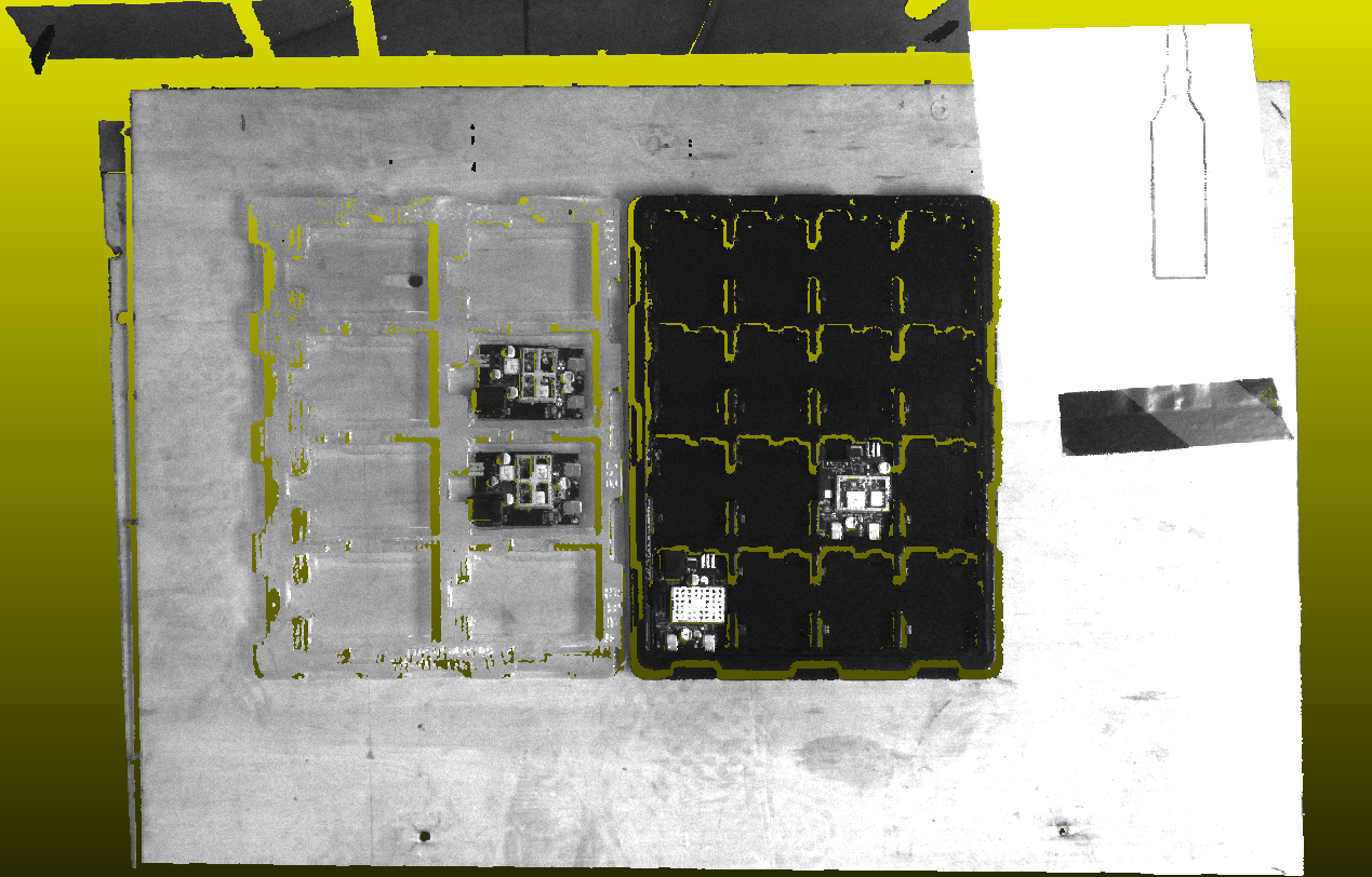
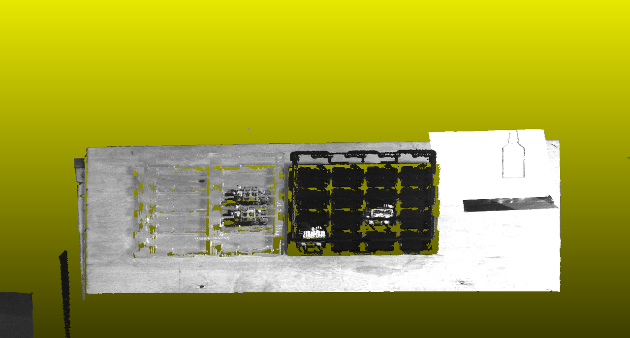
7. XEMA-SC, Air Conditioner Copper Bolt, Poor Effect with Excessive Noise
Solution: Initial exposure was too high - not good! Use HDR mode with two exposure sets: 200/1700 and 1023/5000. Since the distance is short and it's metal, no need for large exposure. The second image shows the adjusted result - even General MacArthur would approve!
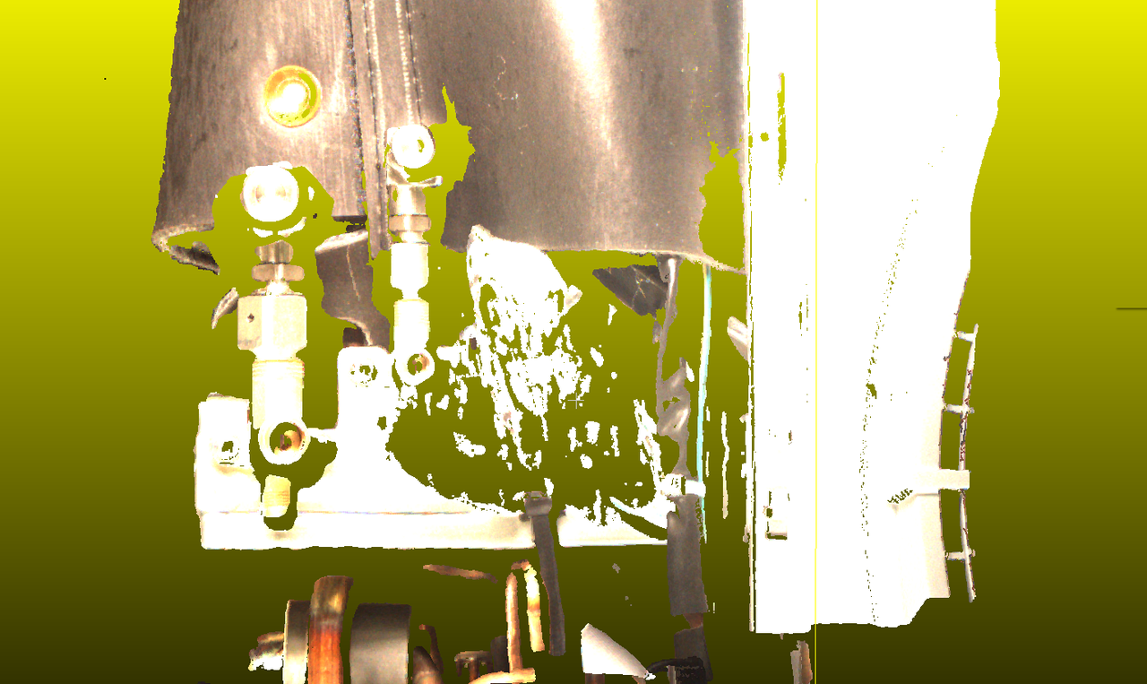
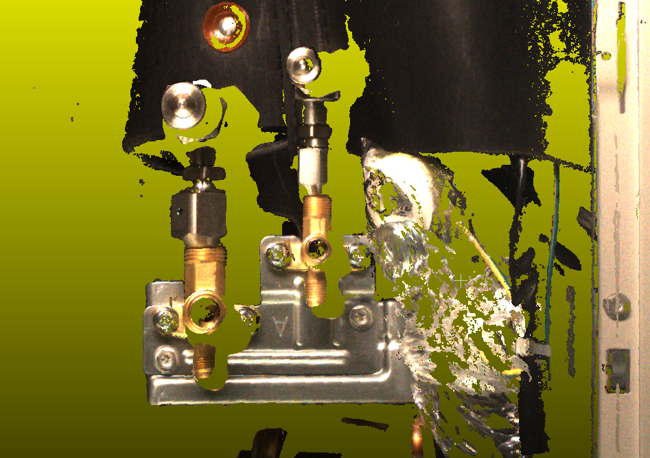
8. XEMA-L, Metal Shaft, Excessive Noise
Solution: For standard local reflective workpieces, use HDR mode without hesitation. Since this is L model at 1.2m distance, use HDR with large exposure 1023/20000 and small exposure 1023/1700. There's a lot of noise - use noise filtering/depth filtering and radius filtering. Optimization often requires multiple iterations - adjust parameters while observing depth map and point cloud. Increase depth filter threshold if needed (don't hesitate to increase by more than 1 at a time). Increase radius filter threshold significantly for better results.
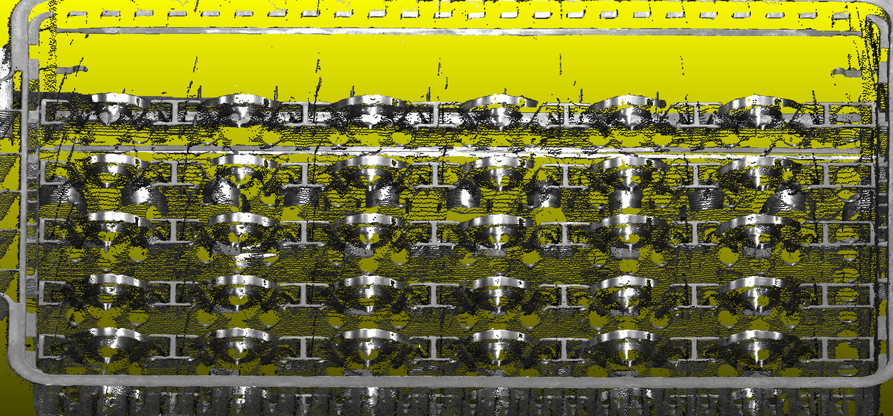
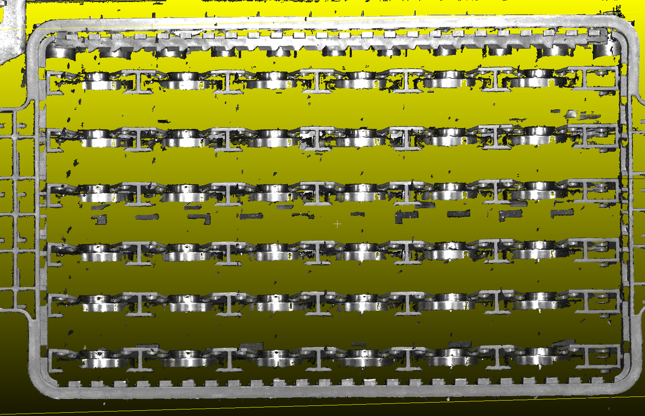
9. XEMA-S, Metal Sheet
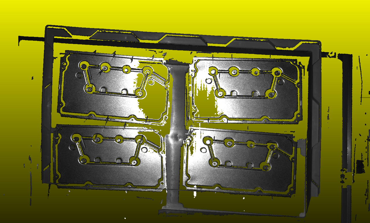
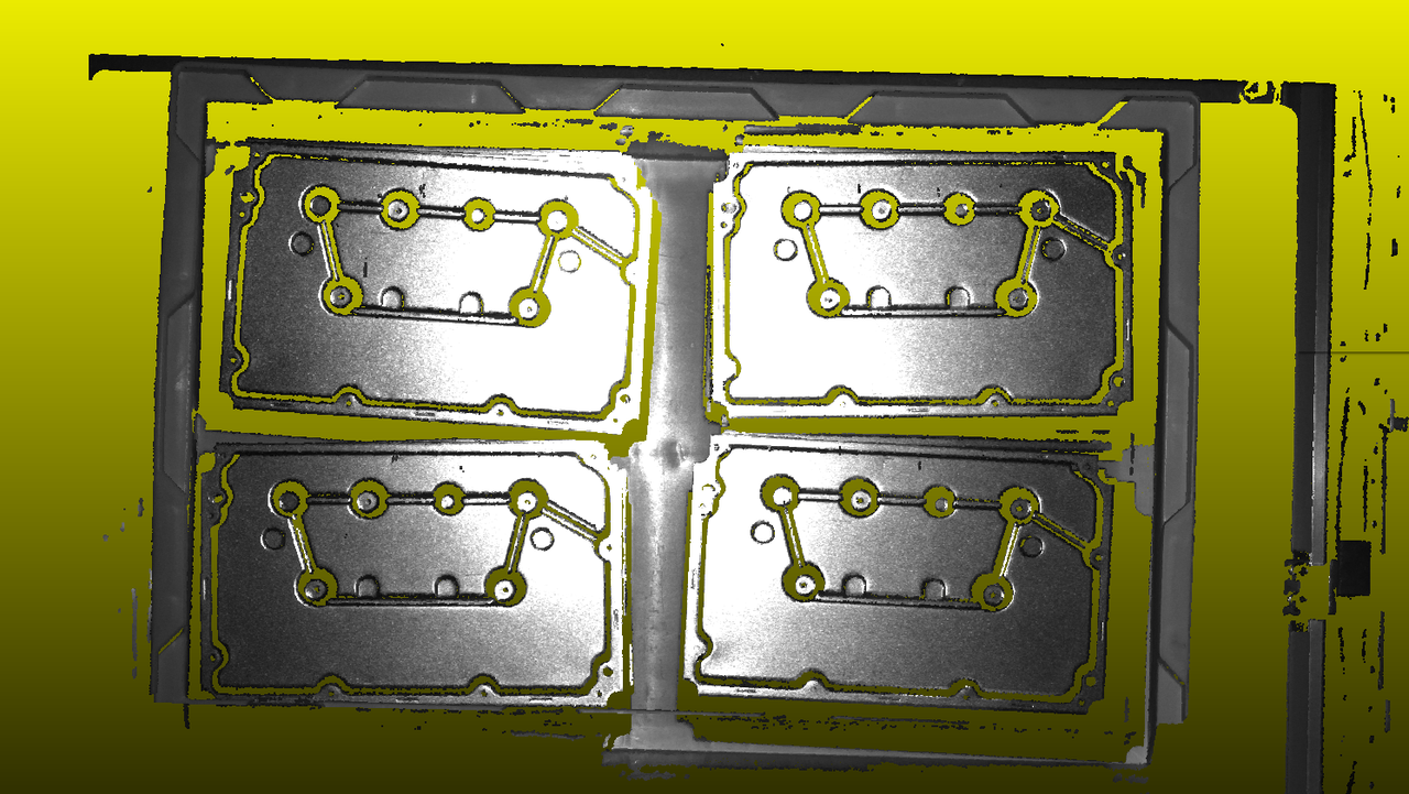
Solution: Remember that for thin metal sheets, there will always be areas with strong local reflection. Using single exposure as shown in the first image results in acceptable edge point cloud but overexposed center with missing point cloud. So we need HDR mode - the universal solution! Use two sets: 500/1700 and 1023/8000. Why 500 projection brightness? Because even with exposure time 1700, it was still overexposed, so I had to reduce the projection brightness appropriately.
10. XEMA-L, Aluminum Ingot, Floating Noise Above
Solution: This noise appears as floating points above the actual workpiece, which is an imaging error. To filter this, increase depth filter value and radius filter strength. Here I set depth filter to 70 (max 100). Normally radius filter (2, 10) is sufficient for general workpieces, but here I use (2, 18). Adjust filter parameters appropriately based on point cloud visualization.
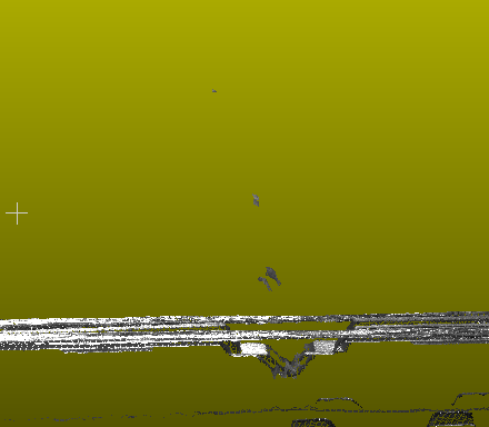
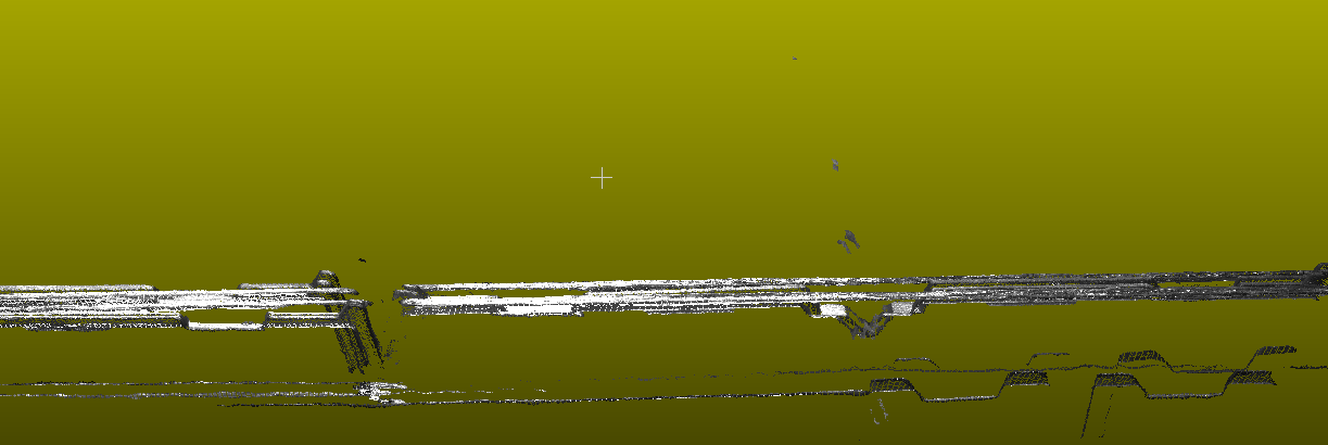
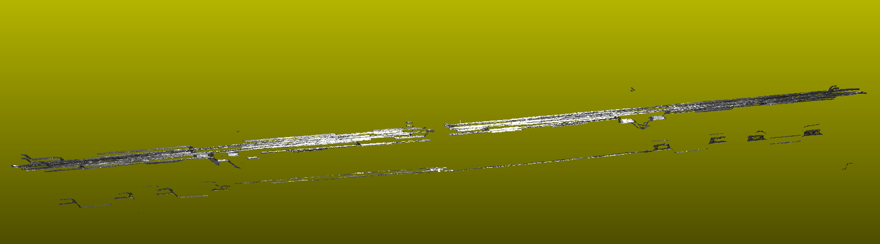
11. XEMA-L, Smooth Metal Ring Workpiece
Solution: The main issue is noise on the inner ring due to reflection. The key is noise filtering while preserving valid information. Increase noise filtering strength until the inner ring appears black in the depth map, indicating noise is filtered out. Enable radius filtering and depth filtering appropriately. Use two-set HDR mode for metal workpiece imaging.
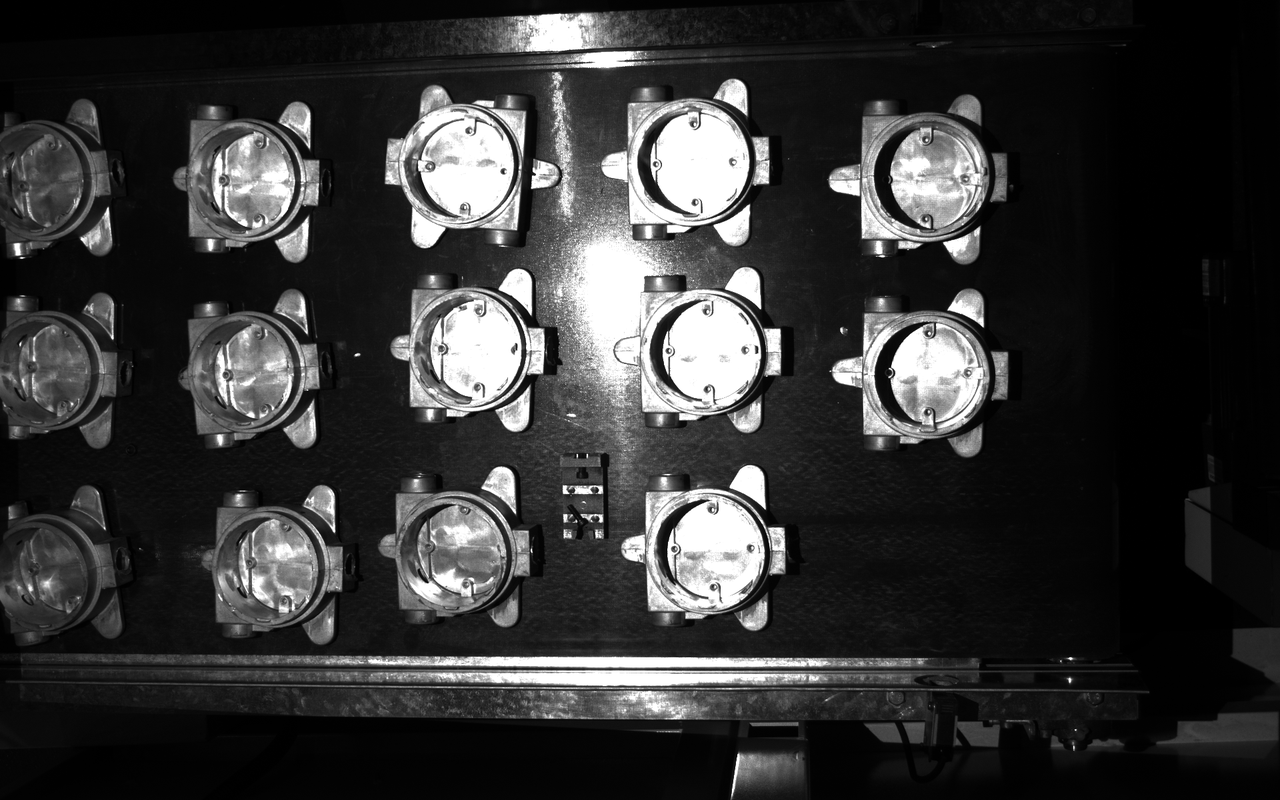
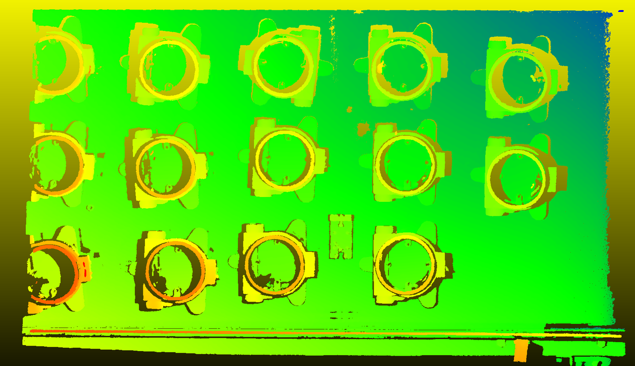
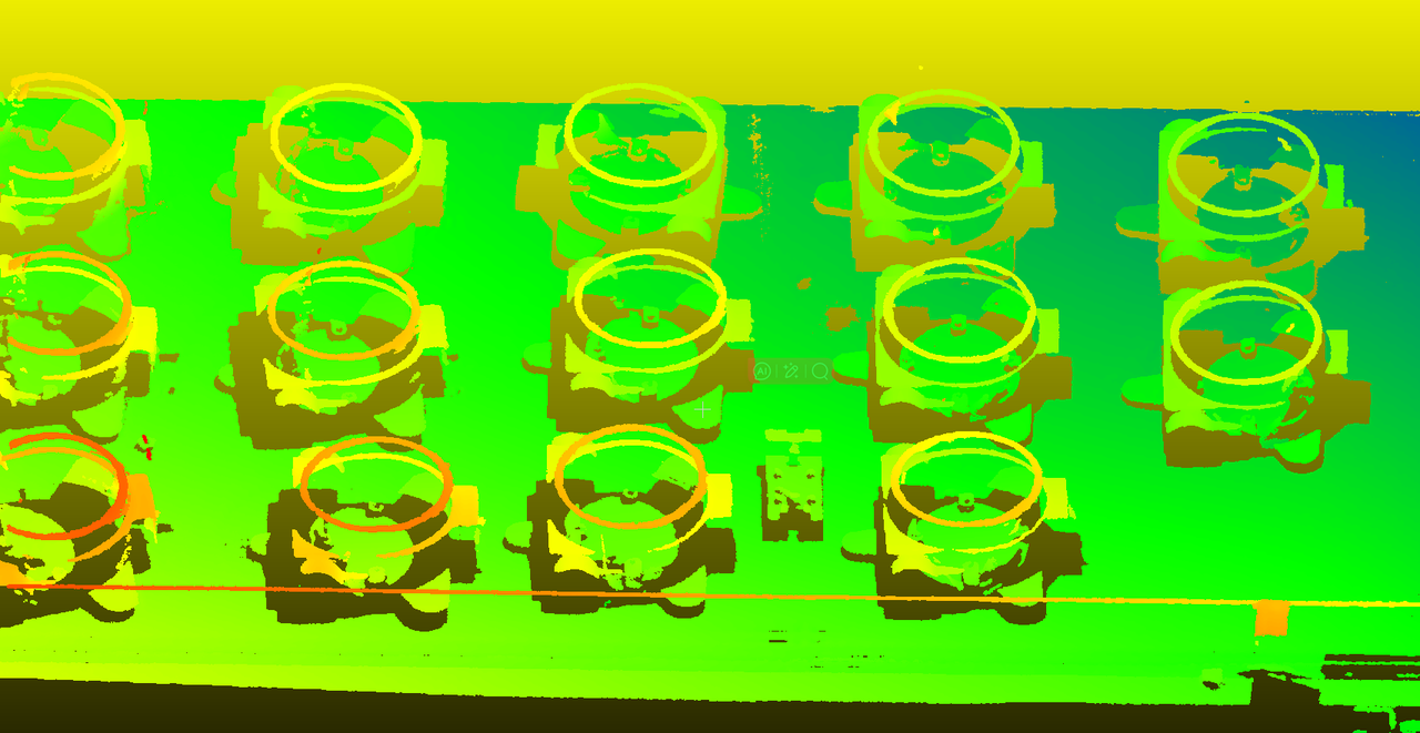
12. XEMA-LC, Parameter Adjustment for High-temperature Workpieces (>1000°C)
Solution: For high-temperature workpieces with uniform high temperature, reflection is not an issue, so single exposure is sufficient. Adjust exposure time based on depth map. For noise, in addition to radius filtering, increase depth filtering and noise filtering strength to effectively remove floating noise points.
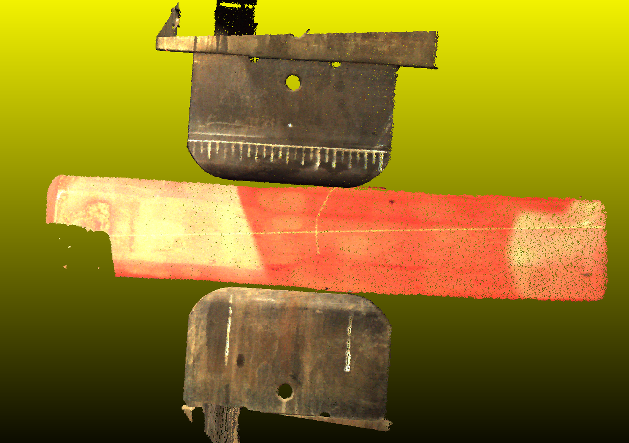
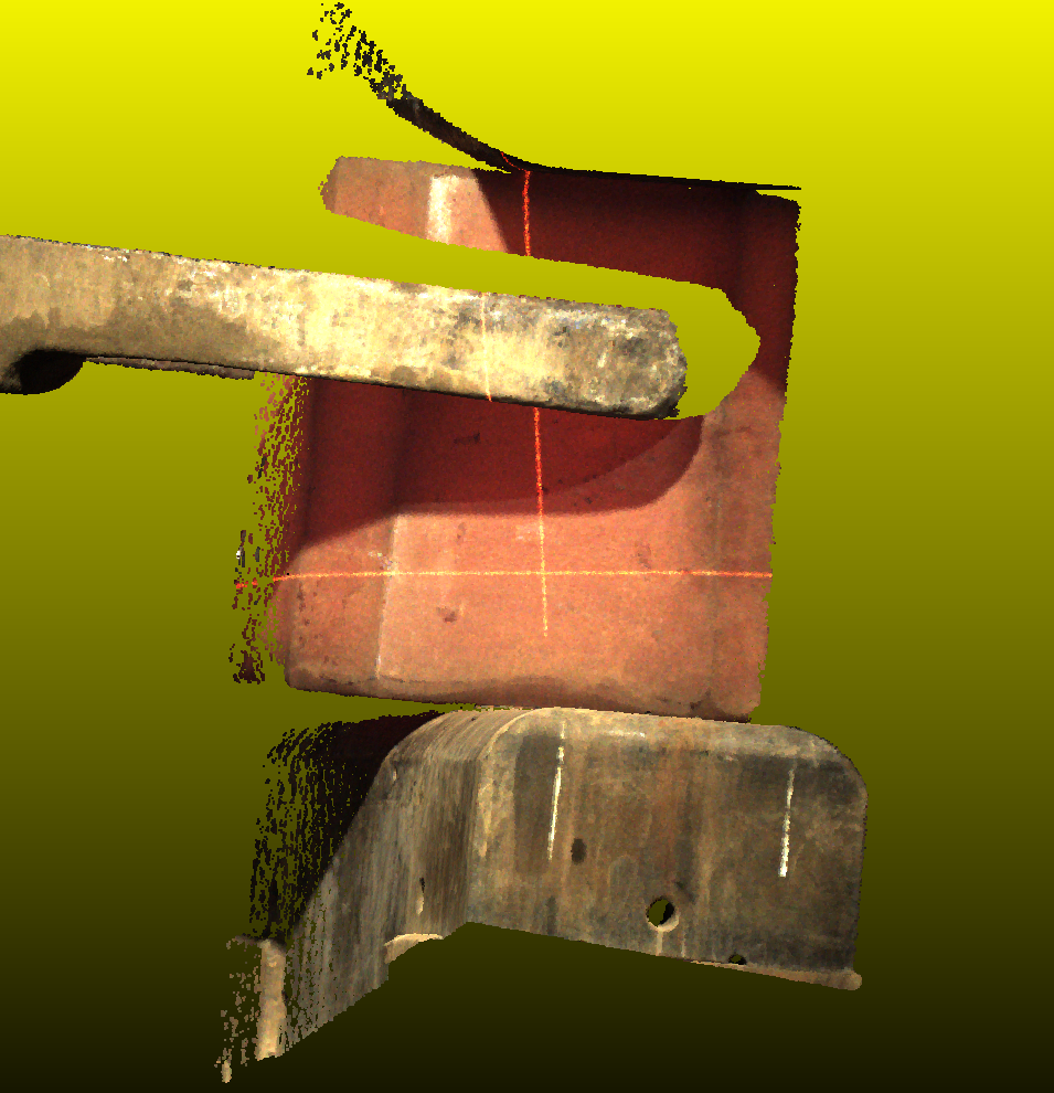
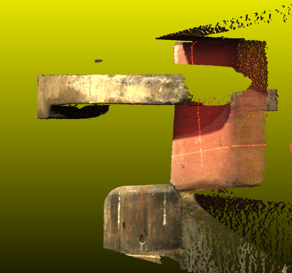
13. XEMA-L, Washing Machine Inner Drum Thread Positioning
Solution: To minimize capture time while ensuring point cloud quality, observe the workpiece first. This is white plastic with no local overexposure, so single exposure is sufficient to save time. Since the requirement is <1 second, enable gain to reduce exposure time. I used gain 5 - higher values like 8 or 10 would introduce too much noise. Reduce exposure to 5000 for acceptable point cloud. When using gain, avoid smoothing as it increases capture time (gain and smoothing are time-wise incompatible). Use radius filtering and noise filtering - avoid depth filtering as radius filtering is sufficient. Noise filtering adds minimal time overhead. Final capture time: 630ms - excellent performance!
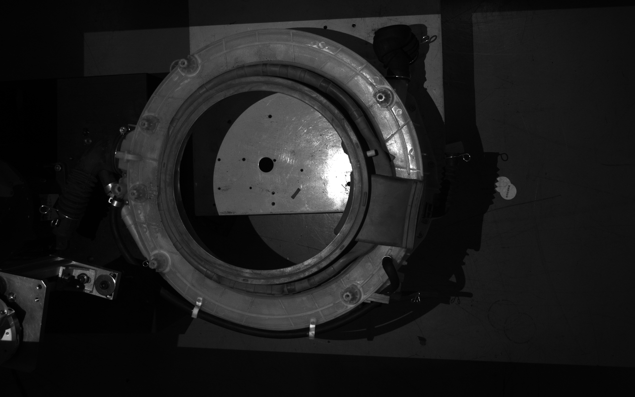
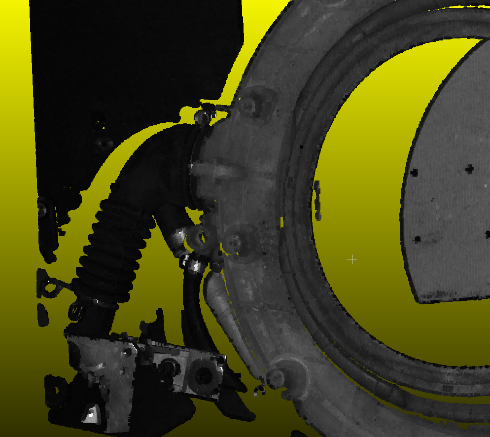
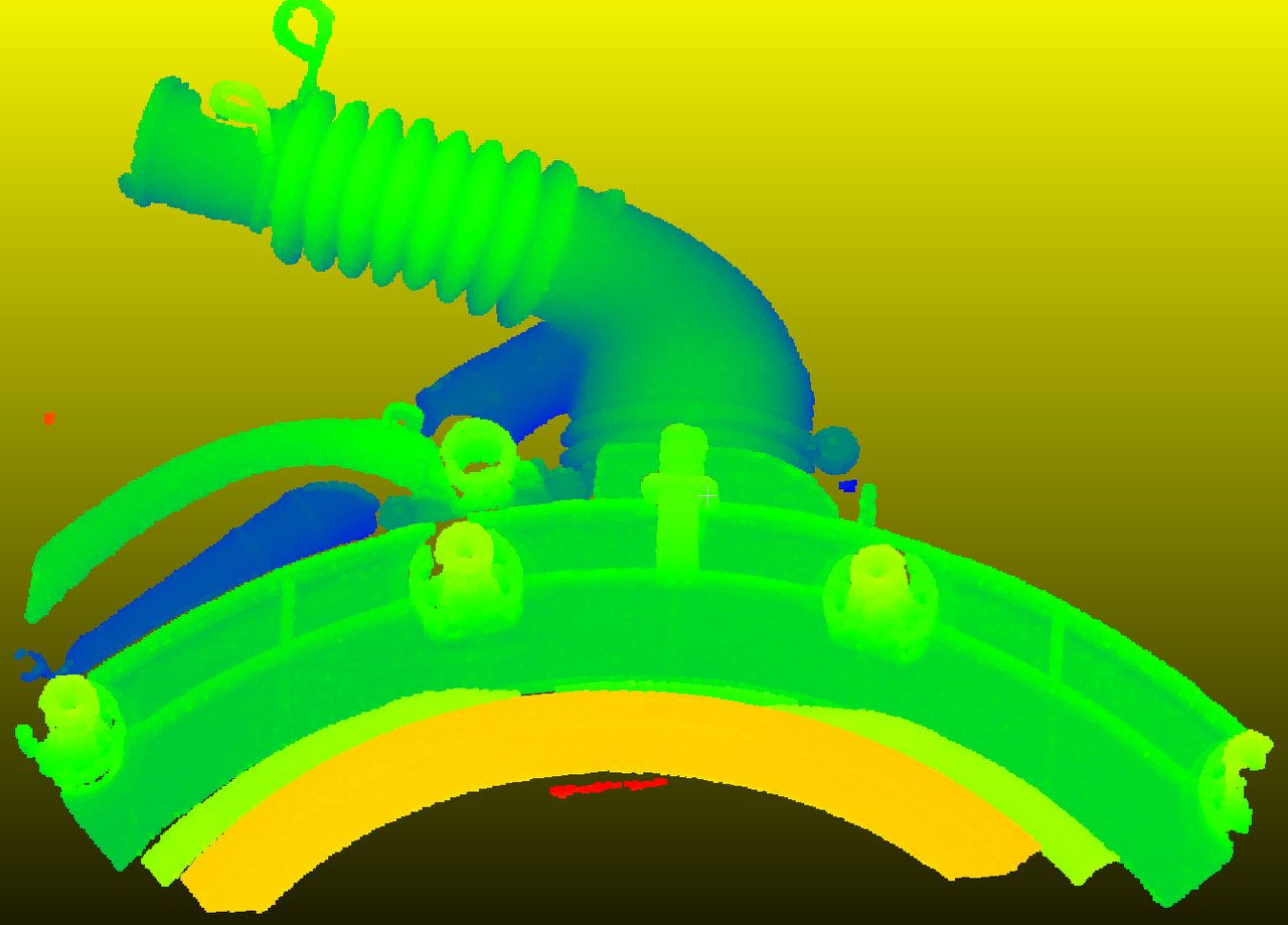
14. XEMA-S, White Plastic and Metal Combination
Solution: For workpieces with metal and non-reflective white plastic, especially when imaged near the edge of the FOV, use two exposure sets: large exposure for dark edge areas and small exposure for the center. Adjust values until both edge and center point clouds are clear. Vertical metal strips at edges will generate significant noise - enable reflection filtering and radius filtering. Filter until noise appears black in the depth map. Enable smoothing if time allows, as it increases capture time.
2. IP Issues
1. On-site Prompt: Different Network Segments
Solution: [To be written]
2. Can Search Camera IP but Cannot Connect
Scenario 1: Wrong Network Segment
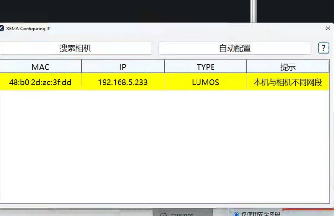
Searching camera shows IP 192.168.5.233 with prompt "Local machine and camera are in different network segments"
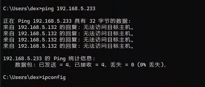
Attempting to PING camera fails
Checking local IP shows three network segments: 169.254.X.X, 192.168.5.X, 192.168.4.X
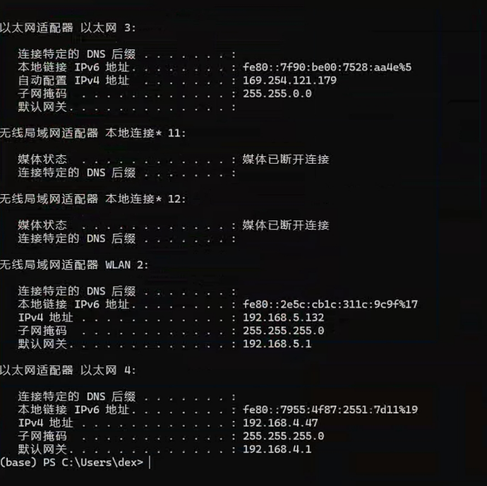
Clearly, the camera was originally using 192.168.5.x for communication but was switched to direct connection on a different network port, causing PING failure.
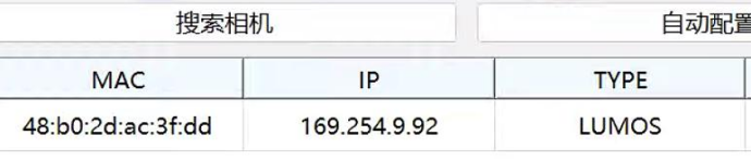
Click [Auto Configuration] to change camera IP to the corresponding network segment (169.254.9.92 in this case) to establish successful connection.
Scenario 2: IP Conflict
In LAN, two devices under the same router have the same IP address (camera and any other device), which may cause communication hijacking between host and camera.
Example:
If both Terminal 1 and Terminal 2 are set to 192.168.1.2
The host sends ARP packet "who is 192.168.1.2" via gateway, and both terminals respond, causing ARP table conflict in the gateway.
Troubleshooting and solution: Run "arp -a" in cmd to check if camera IP matches its physical address. If not, IP conflict exists and IP needs to be changed.
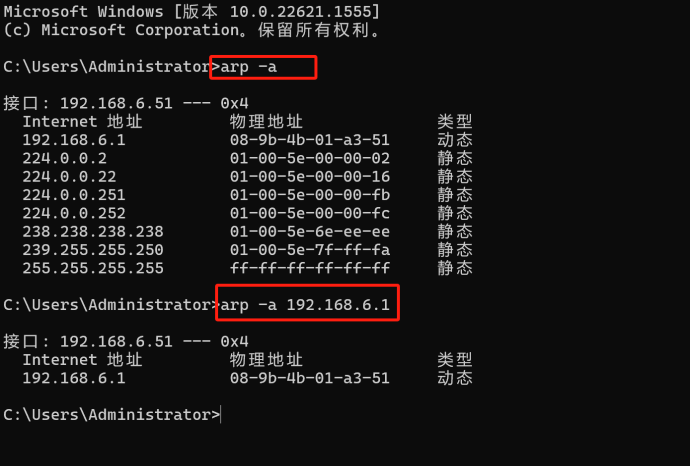
Reference: https://zhuanlan.zhihu.com/p/29011567
3. Finch, Xema Cameras Disconnect Abnormally or Cannot Be Found
Problem: After abnormal disconnection, PickWiz automatically reconnects but disconnects again. In severe cases, cameras cannot be found in the configuration interface.
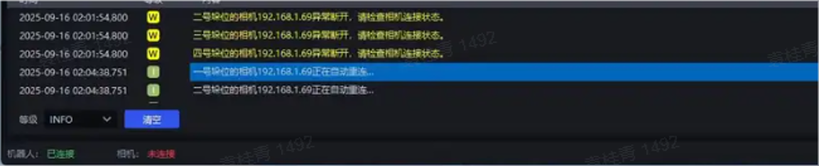
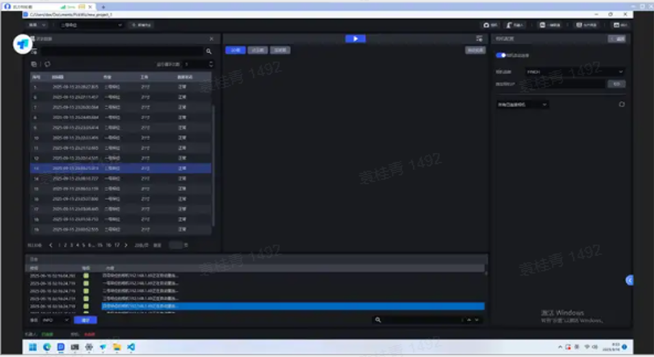
Possible Causes: On-site network instability (NIC IP configuration conflict, damaged network cable), poor network quality preventing camera detection.
Case 1: Damaged network cable
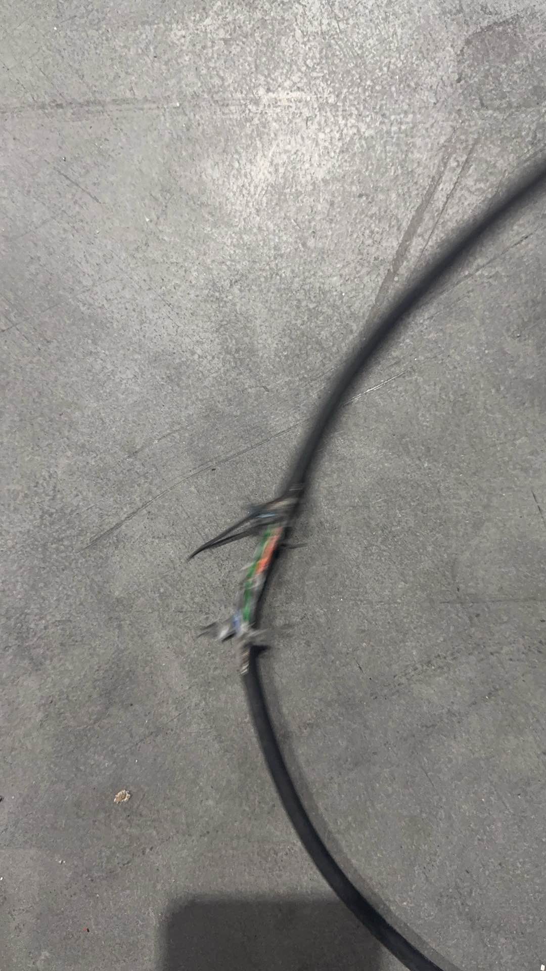
解决方案:
首先排除局域网内ip重复冲突,相机断电,ping相机ip不通,插上相机电可以ping通则为正常;
相机ip地址应当为192.168.x.x开头的固定ip,若为169.254.x.x则需要修改相机、工控机为固定ip;
下载以下压缩文件并解压,然后打开终端运行解压后的 ping_ip.exe 工具,并在命令后加上 “相机的 IP 地址”(如:ping_ip.exe 192.168.1.69)测试 PickWiz 与相机之间的网络是否连通。
当相机异常断连/搜索不到时,若ping相机IP的结果显示 “超时”“丢包” 等异常,说明相机故障的原因就是网络不稳定。若ping相机IP的结果显示一切正常,说明相机故障的原因不在于网络,需要进一步排查相机硬件等其他异常情况。
三、现场外参校正问题
相机由于运输,温度,结构应力等多方面因素,会导致相机精度变差,以下是对于xema系列相机的一个详细的外参校正的方法:
XEMA系列相机外参校正方法
1,取图
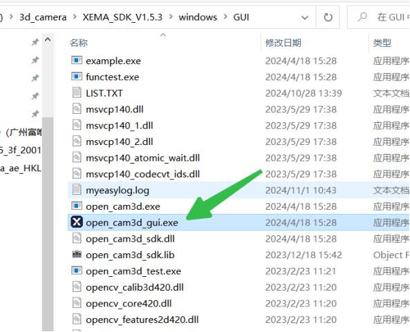
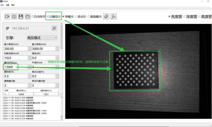
1)相机固定在工作距离下,sdk中打开open_cam3d_gui.exe,连接相机,将标定板平放到视野正中心,采集,调节最佳的曝光时间,使得标定板刚好不过曝;例如:
2)在gui都在路径,新建一个文件夹储存采集图片,取名为:capture;
3)开始取图,需要拍摄 5 组图片,进入sdk_gui所在路径,鼠标右键打开终端,运行.\open_cam3d.exe,找到采图指令(如下图红框指示):
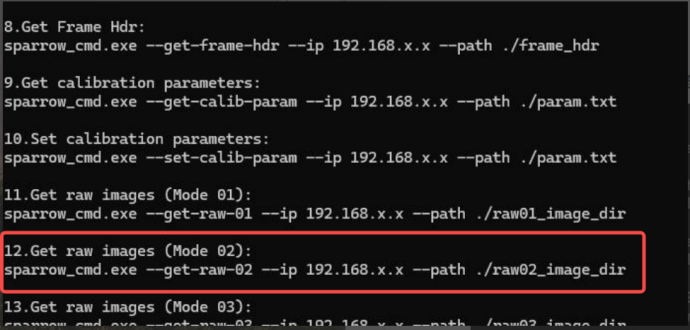
4)执行拍照命令:./open_cam3d.exe --get-raw-02 --ip 192.168.6.63 --path ./capture/00;
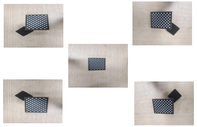
192.168.6.63为相机IP,根据实际相机IP对应更改即可,00为第一组图片,一共5组00-04,每个位置采集1个位姿,如下图所示;中心平放,视野的四个角垫起各一张;
2,相机标定
先将相机原本的标定文件导出到本地,还是进入gui都在路径,右键打开终端,执行指令:open_cam3d.exe --get-calib-param --ip 192.168.6.63 --path ./param.txt
导出后,回到终端,打开校正指令:终端运行.\calibration.exe,执行下面的校正指令:
./calibration.exe --correct --use patterns --path ./capture/ --version 3010 --board 20 --param-in ./param.txt --param-out ./param.txt
(IP根据实际相机IP更改,board 20是指标定板大小,根据实际更改)
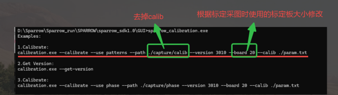
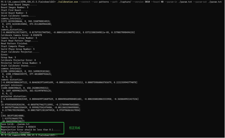
3)等待校正结束后,终端执行写入标定参数:
执行./open_cam3d.exe --set-calib-looktable --ip 192.168.x.x --path ./param.txt,等待写入;
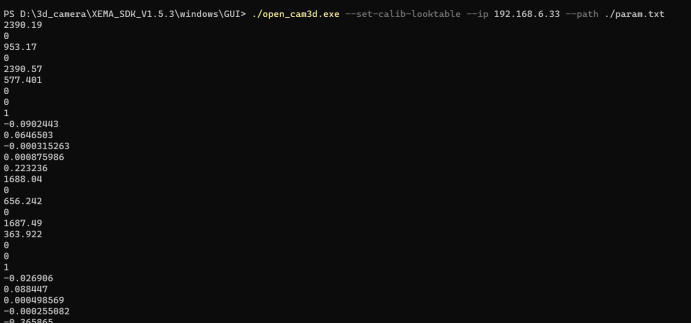
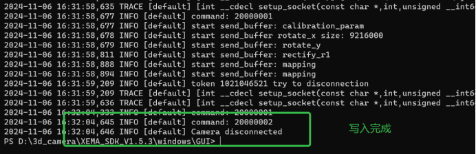
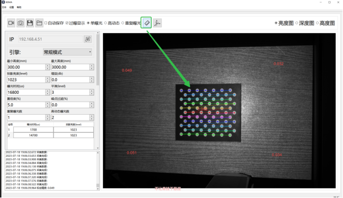
4)写入标定参数后,GUI连接相机,放置标定板采集,查看精度值,例如;
四、其他问题
1、finch部分相机出货版本,彩色模式不兼容高动态,需要更新0925固件
2、finch相机在彩色模式下的手眼标定转黑白模式时标定坐标系发生改变导致抓取异常
问题:
解决方法:彩色模式和黑白模式下的手眼标定可进行转换,暂时提供以下工具进行更新,后续该功能将集成到软件中。
3、结构光相机点云异常缺失问题:
排查是否灯光频闪,如果频闪请关灯看是否改善;
排查是否过曝,过曝区域的点云会存在缺失,如果外部光源导致的过曝(镜面反光,很亮),请遮光,如果曝光值(例如大于80000)过大导致,请减少曝光值;
排查是否欠曝,物体太黑,曝光时间太短会导致,解决办法,增加曝光时间及投影亮度;
排查是否镜片脏污,脏污会导致点云异常缺失,解决方法:使用镜头布擦拭相机镜片;
如下所示关灯后仍然点云缺失,为镜片脏污导致;
4、XEMA相机螺纹胶批次查询:
螺纹胶增加了机器的抗震动能力,在眼在手上的项目表现效果更佳;
自行查询相机序列号,序列号中包含相机的生产日期,25年10月后所生产机器为打螺纹胶的,否则无螺纹胶;
5、结构光相机节拍过长:
部分参数参考节拍(表格)
排查网络测速;
固件信息查看;
联系相机支持人员;