Camera Calibration Specification
Calibration and marking must use single exposure to adjust exposure time, and enable overexposure display to judge brightness
After on-site calibration, switch back to the previously used parameter configuration to complete subsequent work
Non-Stereo Cameras
1. Calibration Board Model Selection
The calibration board models for XEMA and FINCH are distributed as follows. Strictly follow this specification, otherwise incorrect calibration board model (too large or too small) will cause recognition difficulties.
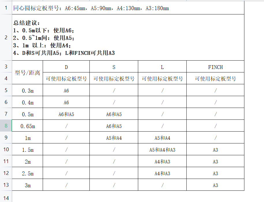
SPARROW uses A6 model
Stereo cameras: Calibration board model to be determined
2. Number of Calibration Board Images
Except for stereo cameras, all other models use 5 images as calibration data
3. Placement Position
Place one flat at the center, and the rest at tilted angles. The optimal placement angle for calibration board is 15-30°. The tilt angle should not be too large or too small


4. Error Cases and Correct Methods
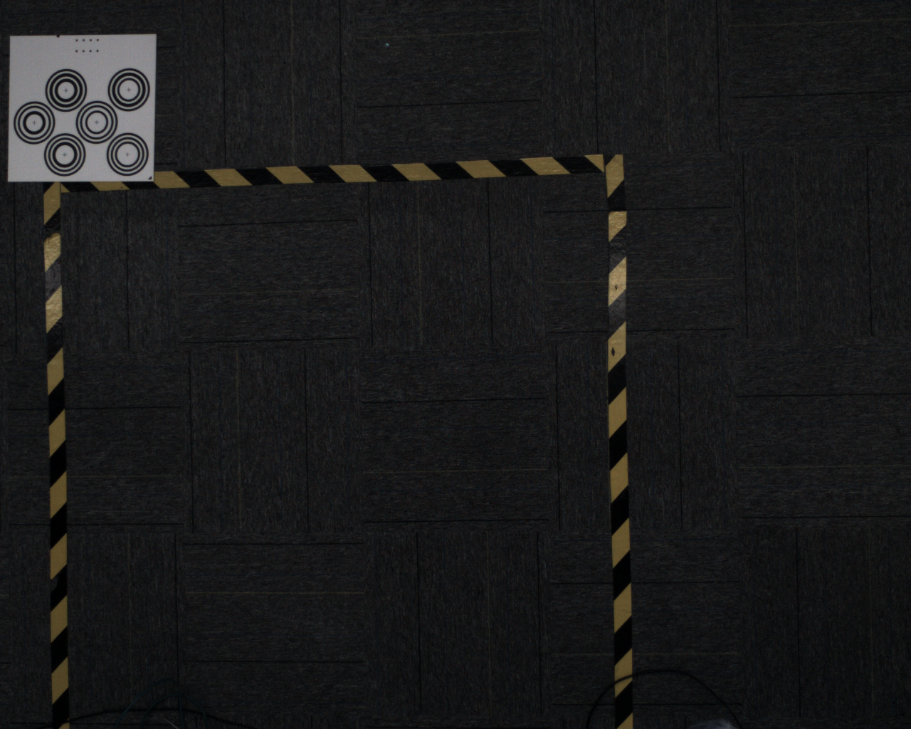
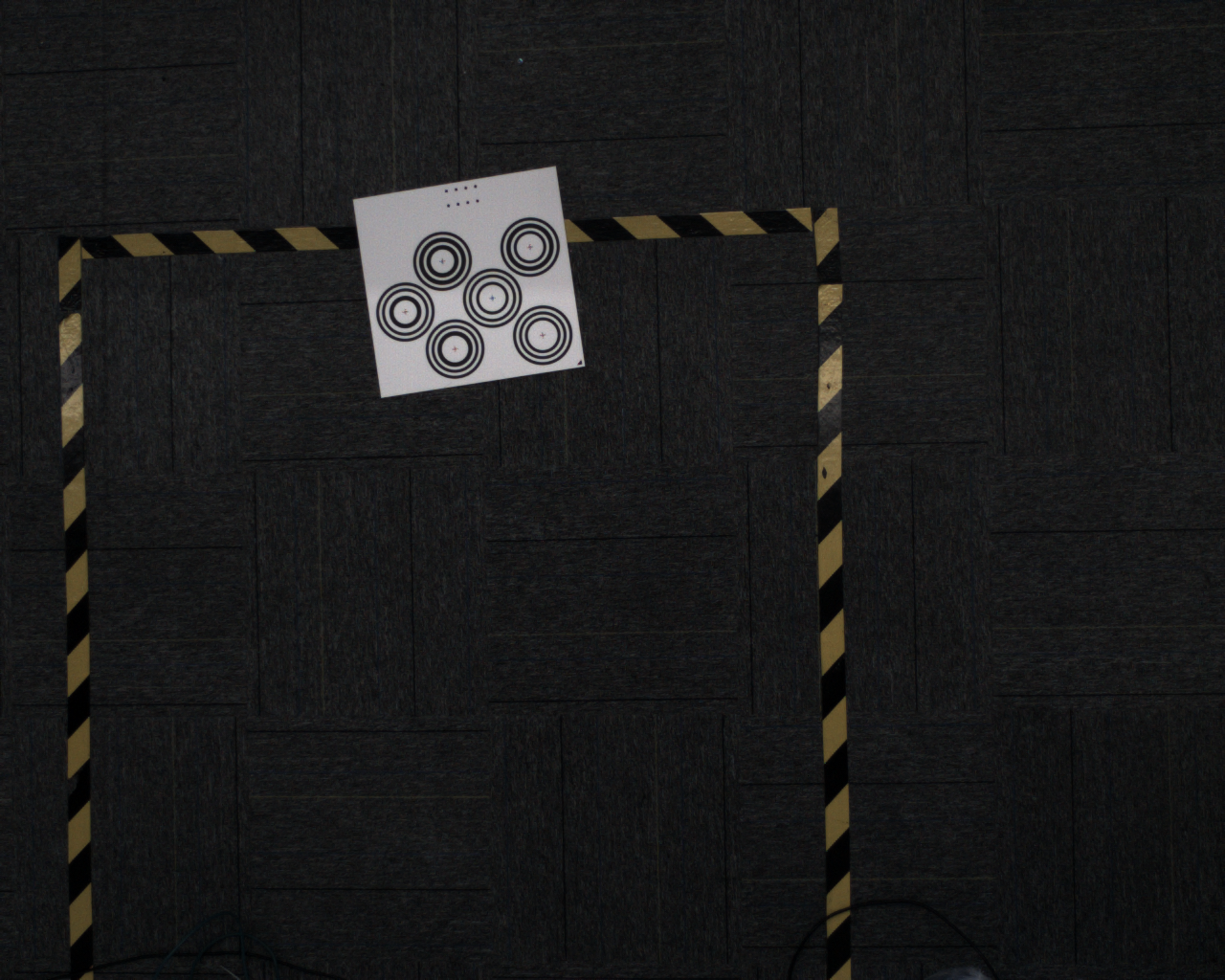
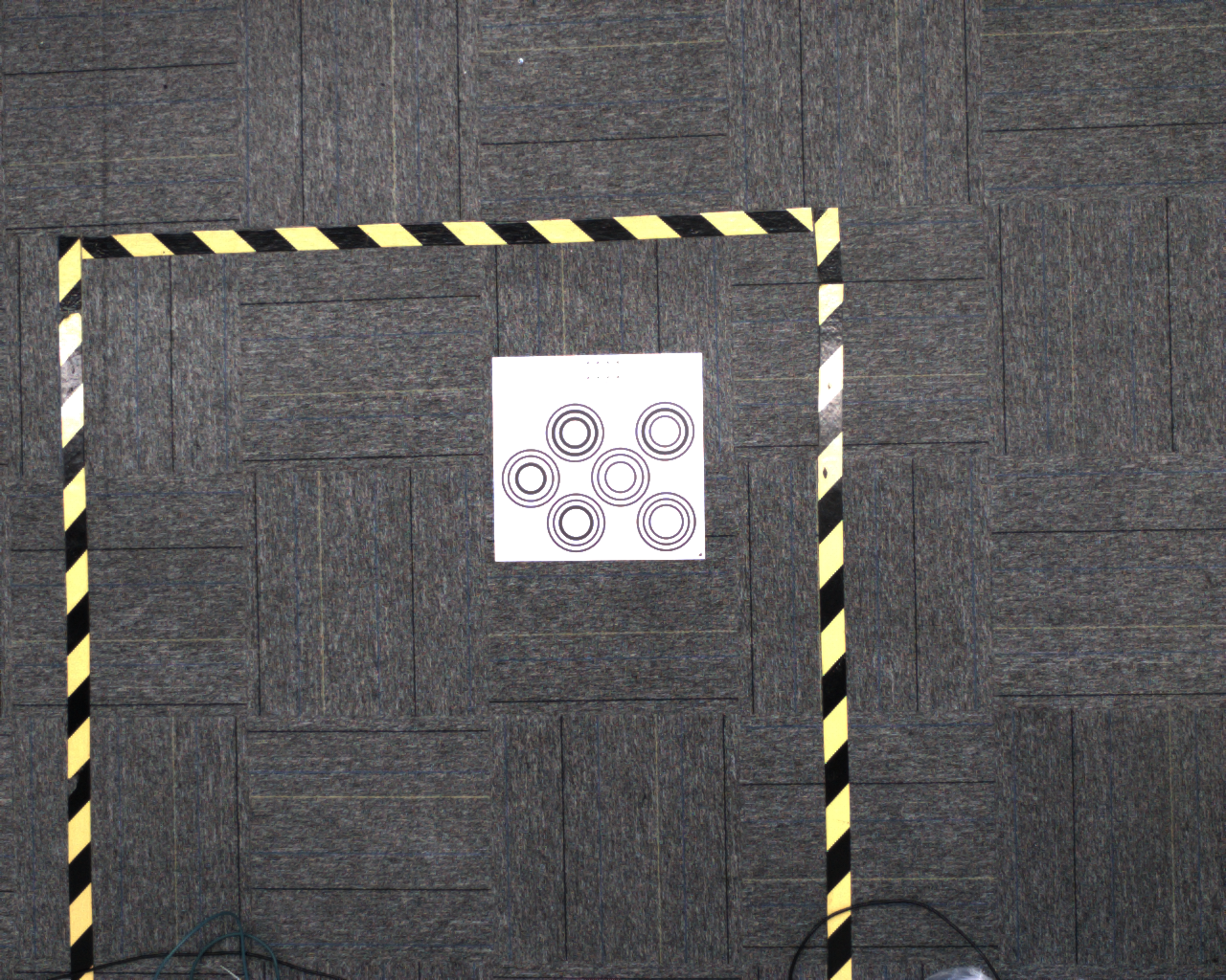
- Error 1: Incorrect Placement Position and Correct Method
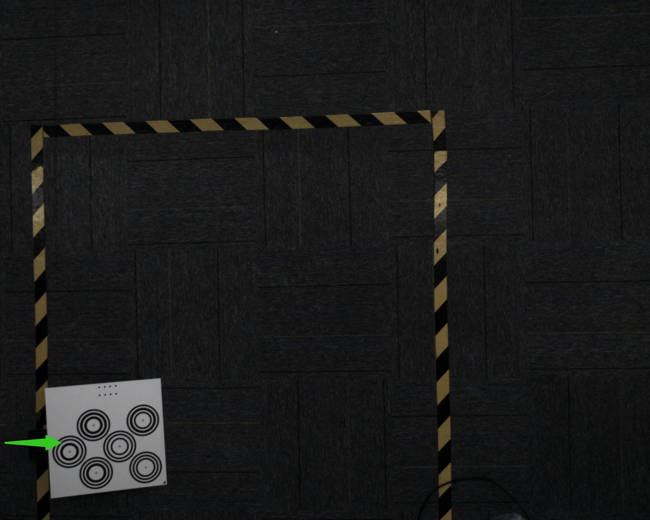
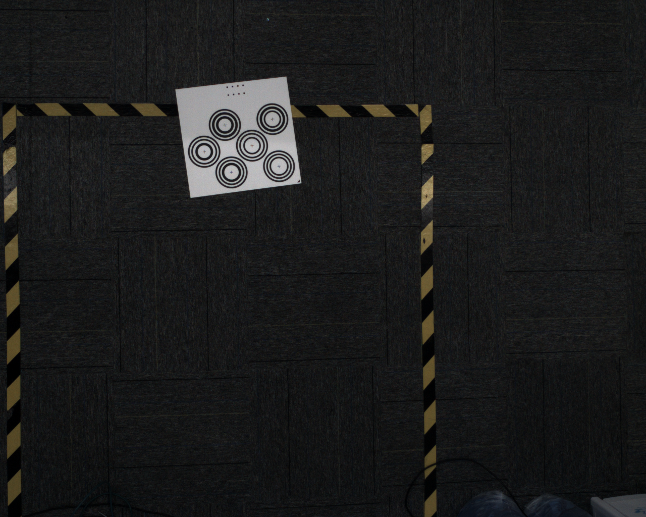
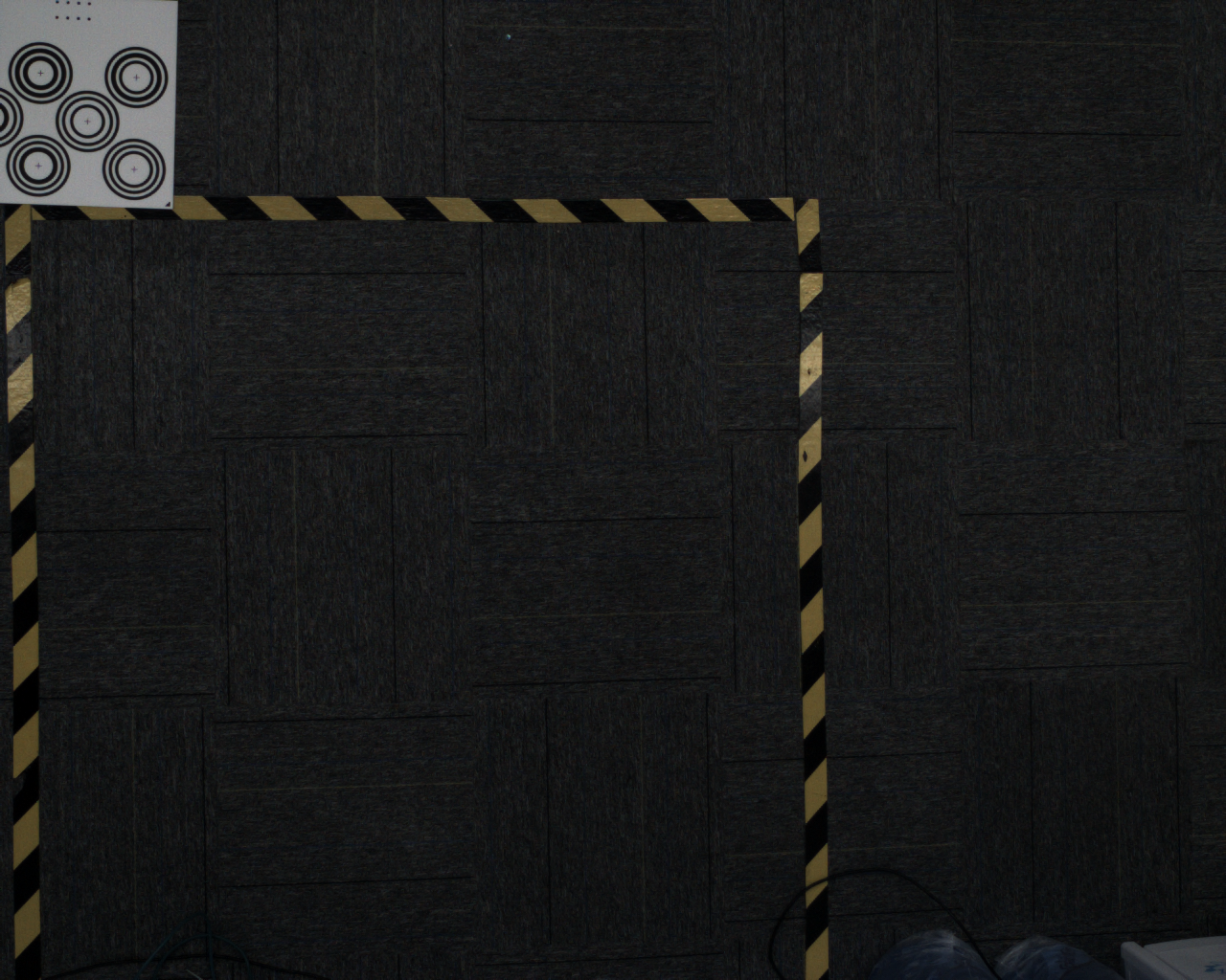
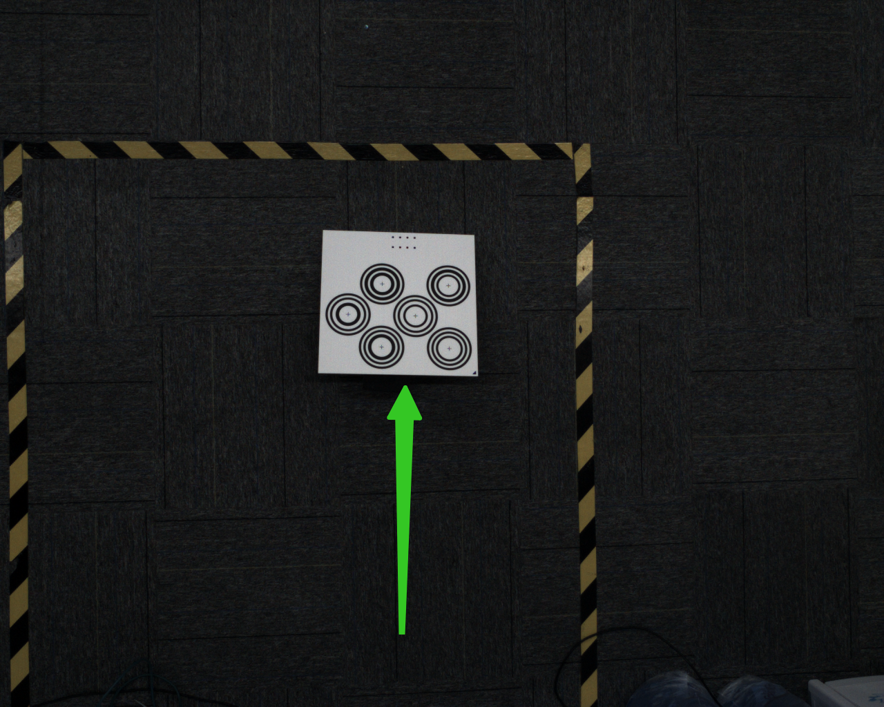
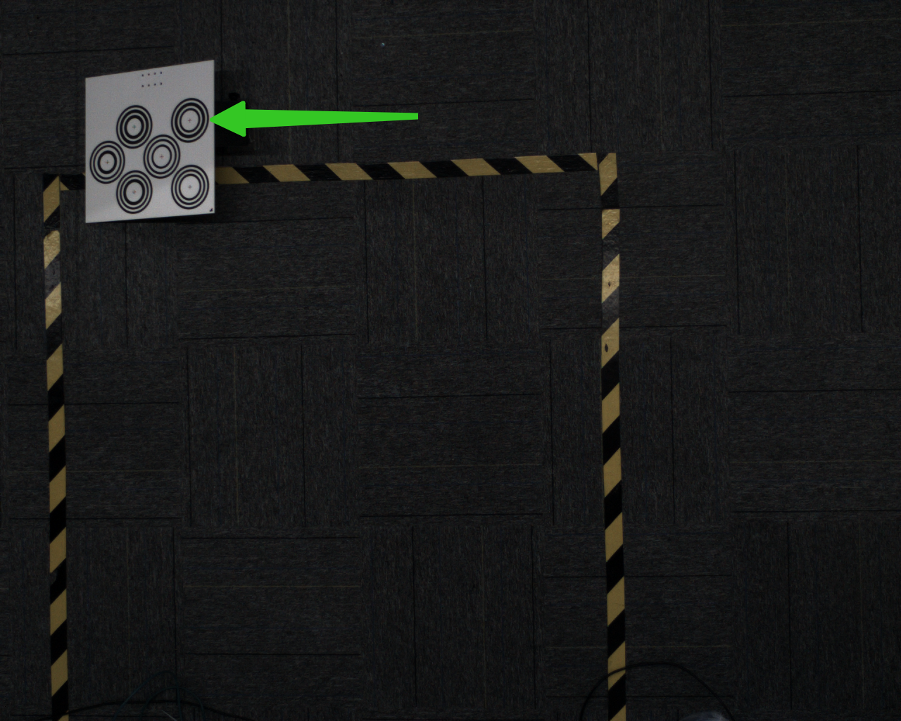
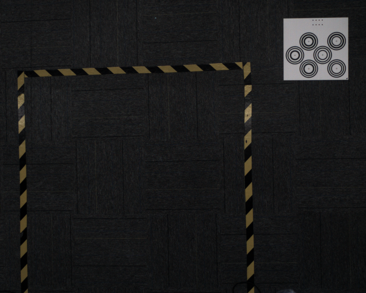
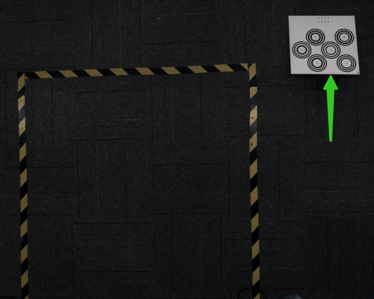
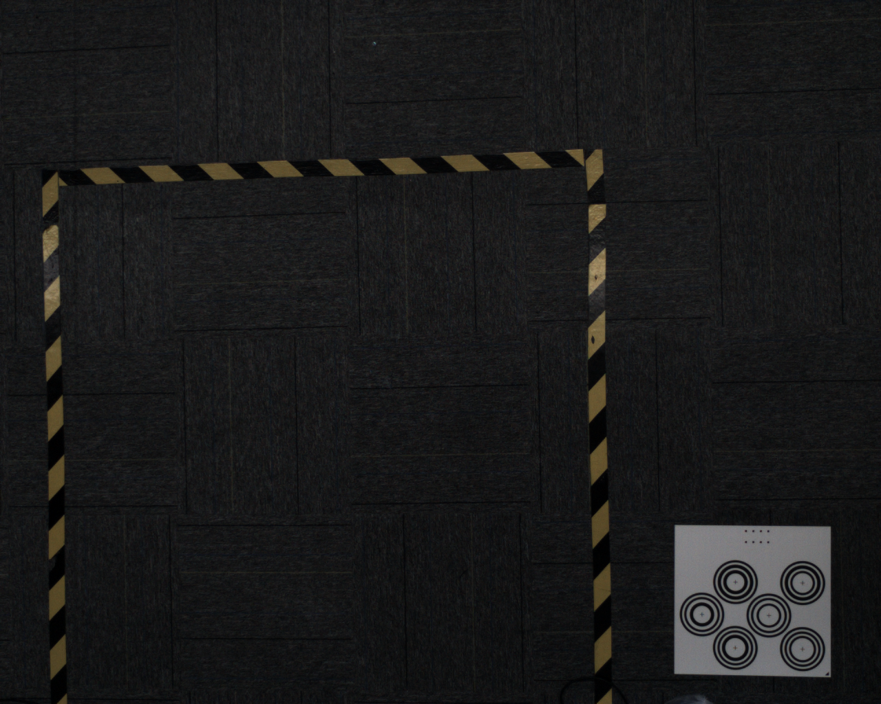
The following image shows incorrect placement position. Although it's within the field of view, it's too close to the center, not covering the edge areas, which affects calibration accuracy
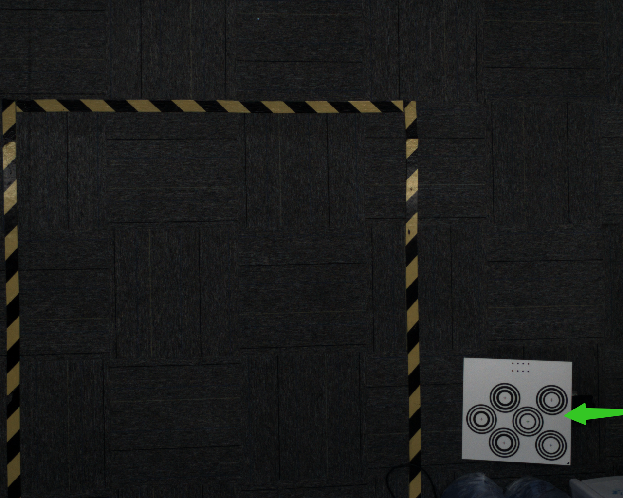
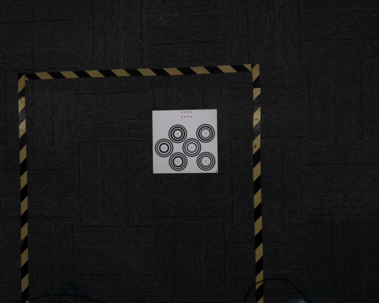
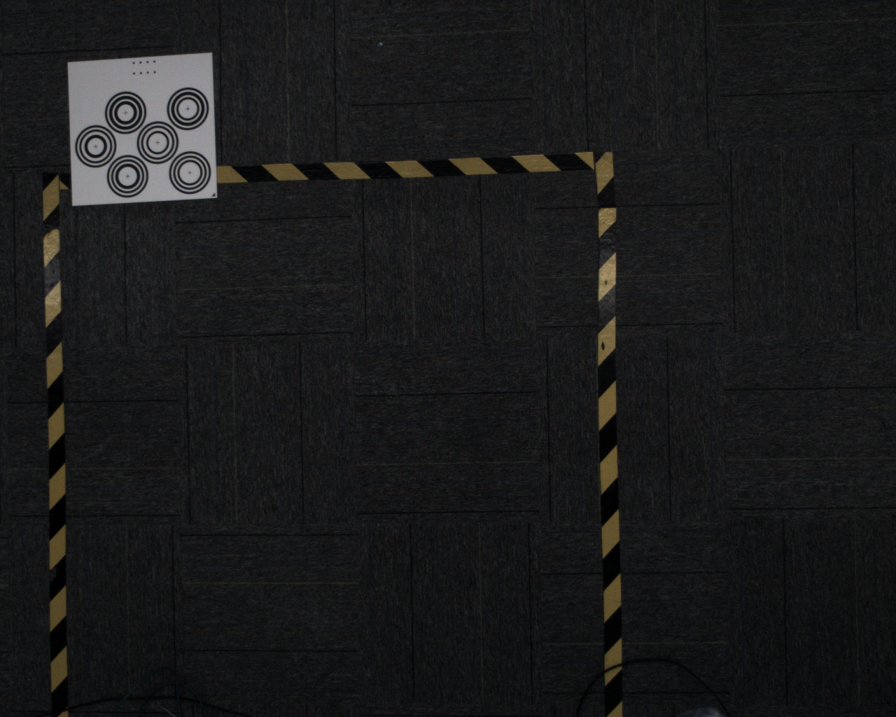
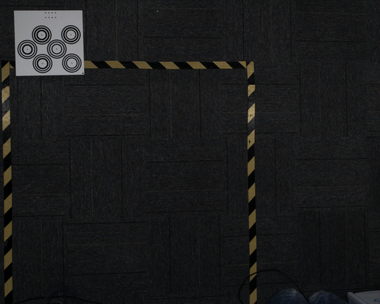
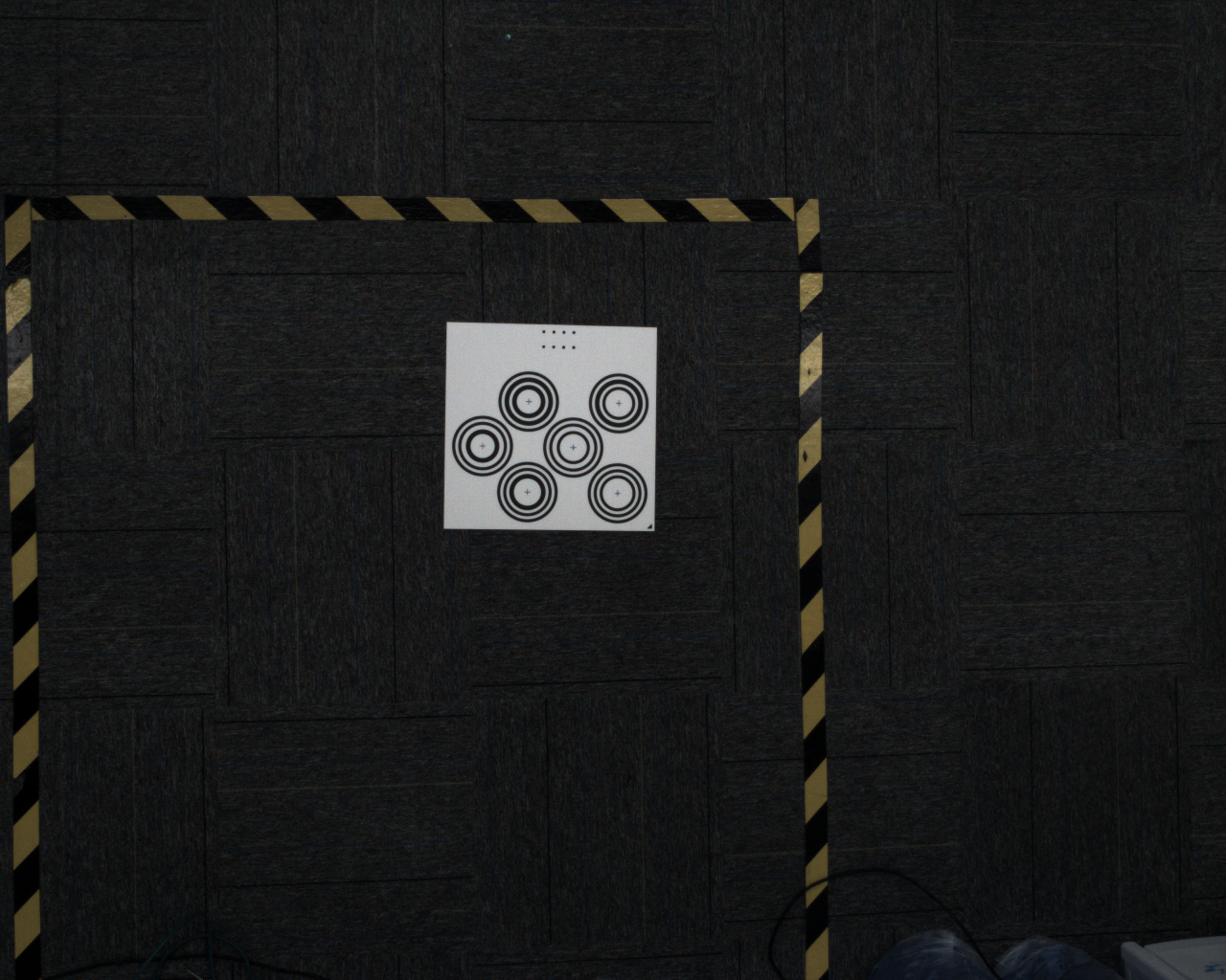
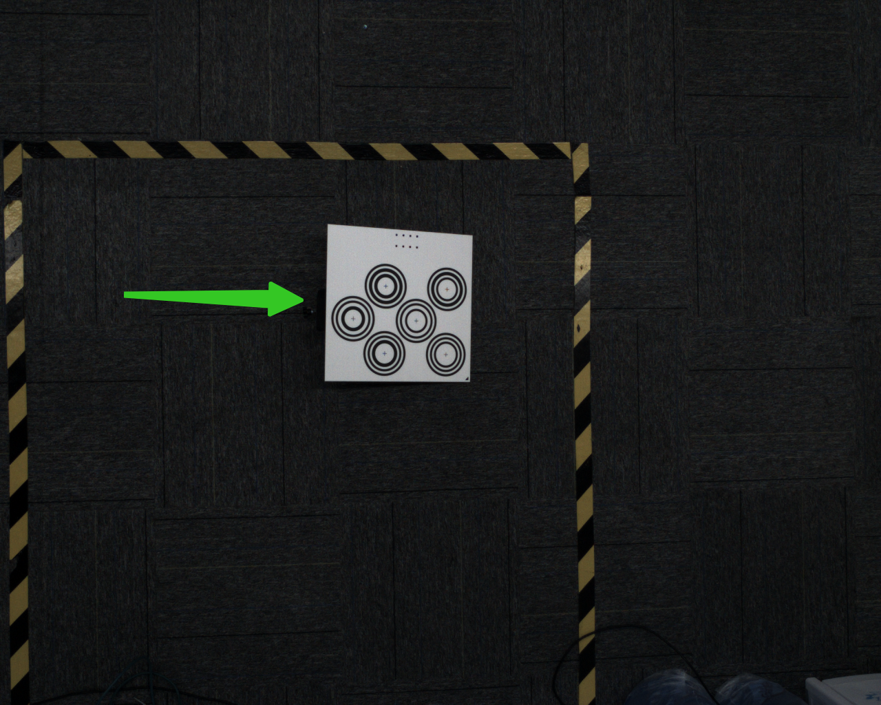
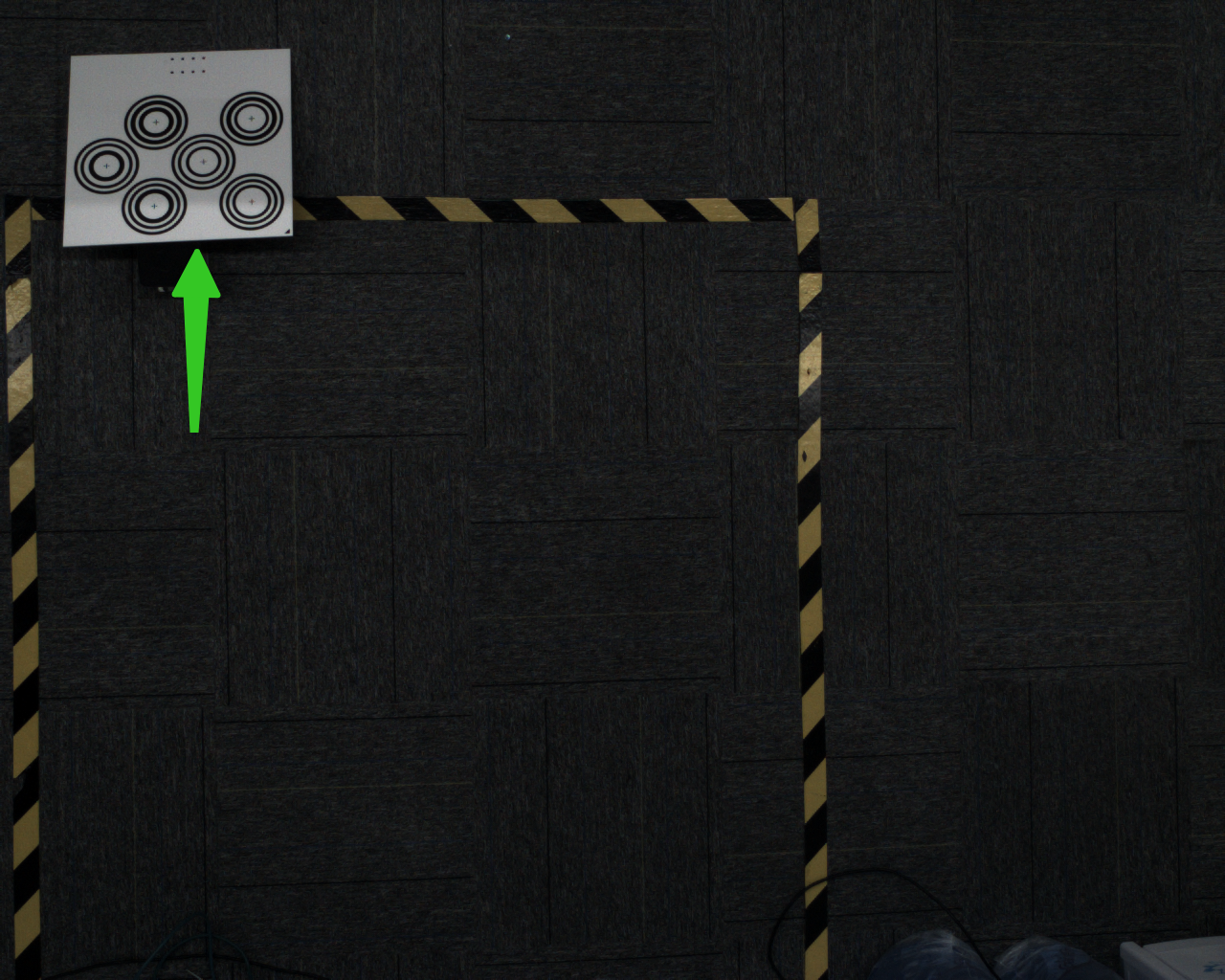
Correct placement is shown below: close to the edge but not exceeding the field of view of left and right cameras

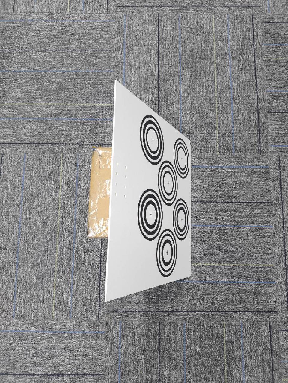
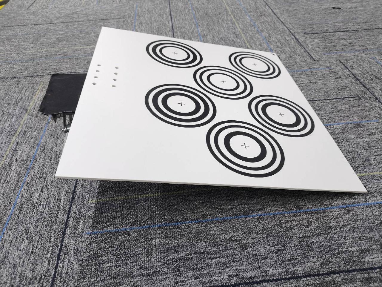
- Error 2: Incorrect Placement Angle and Correct Method
The optimal placement angle for calibration board is 15-30°. The tilt angle should not be too large or too small
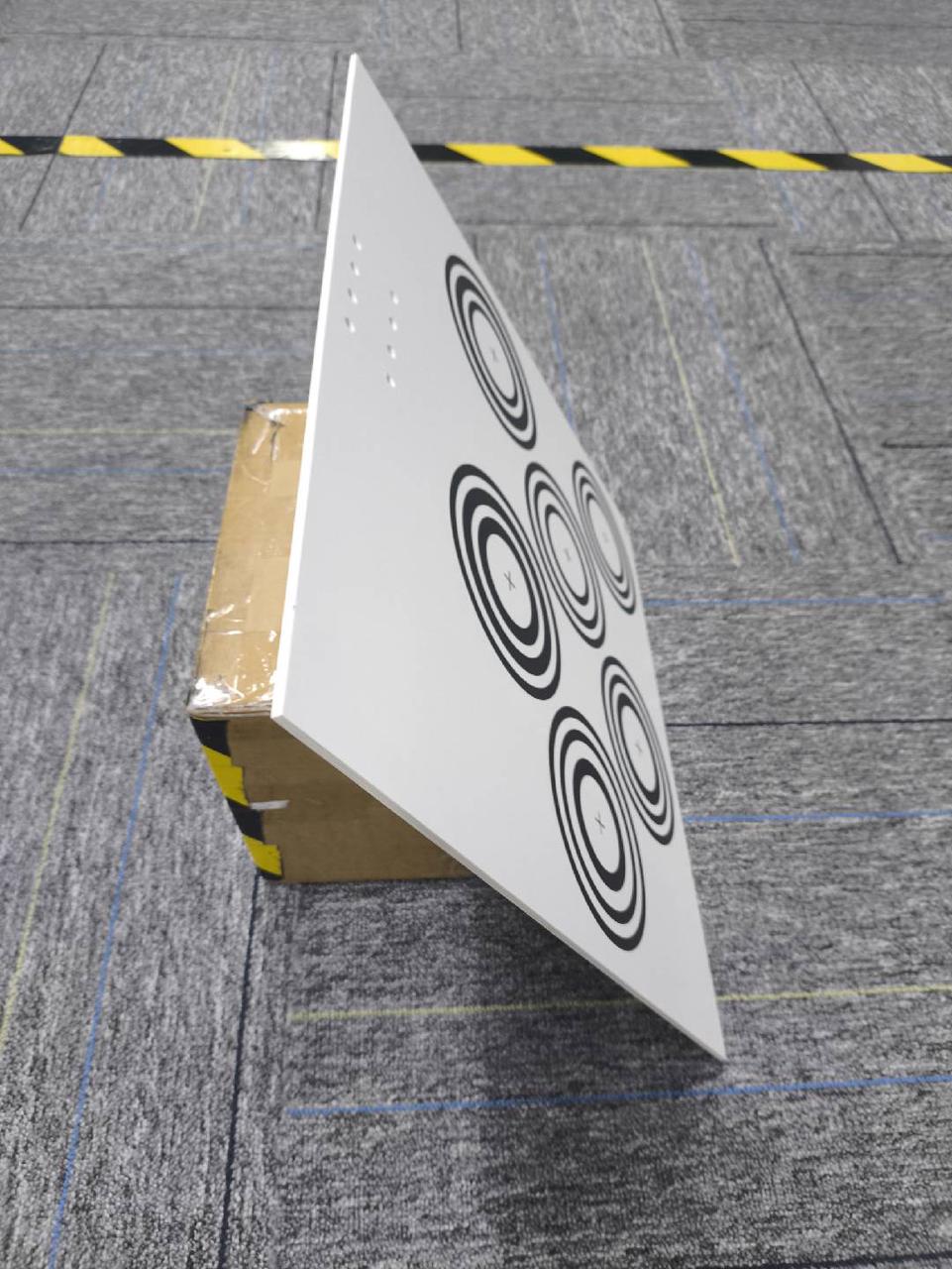
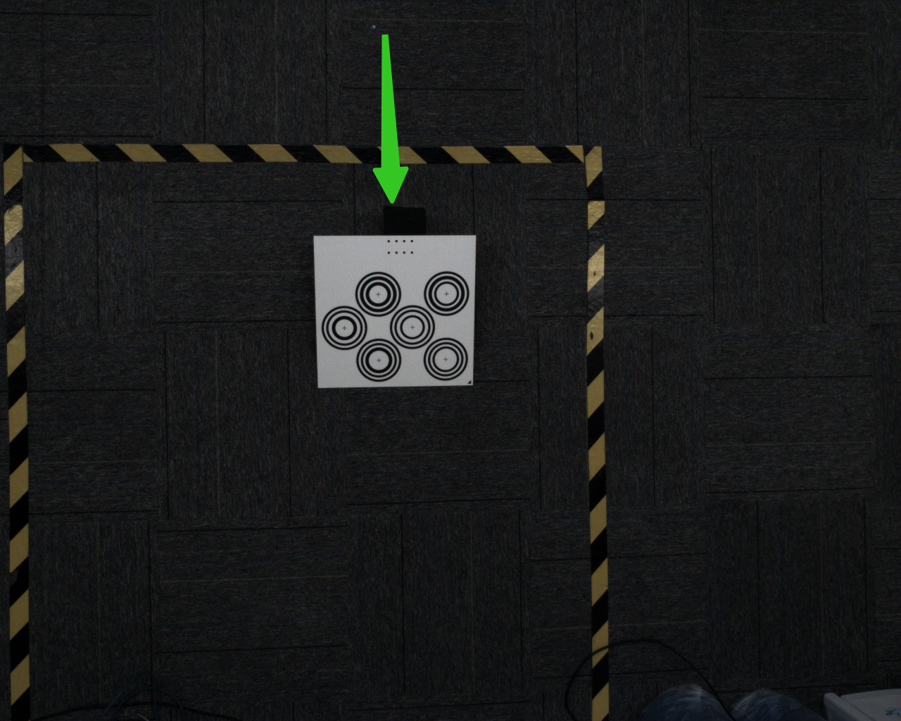
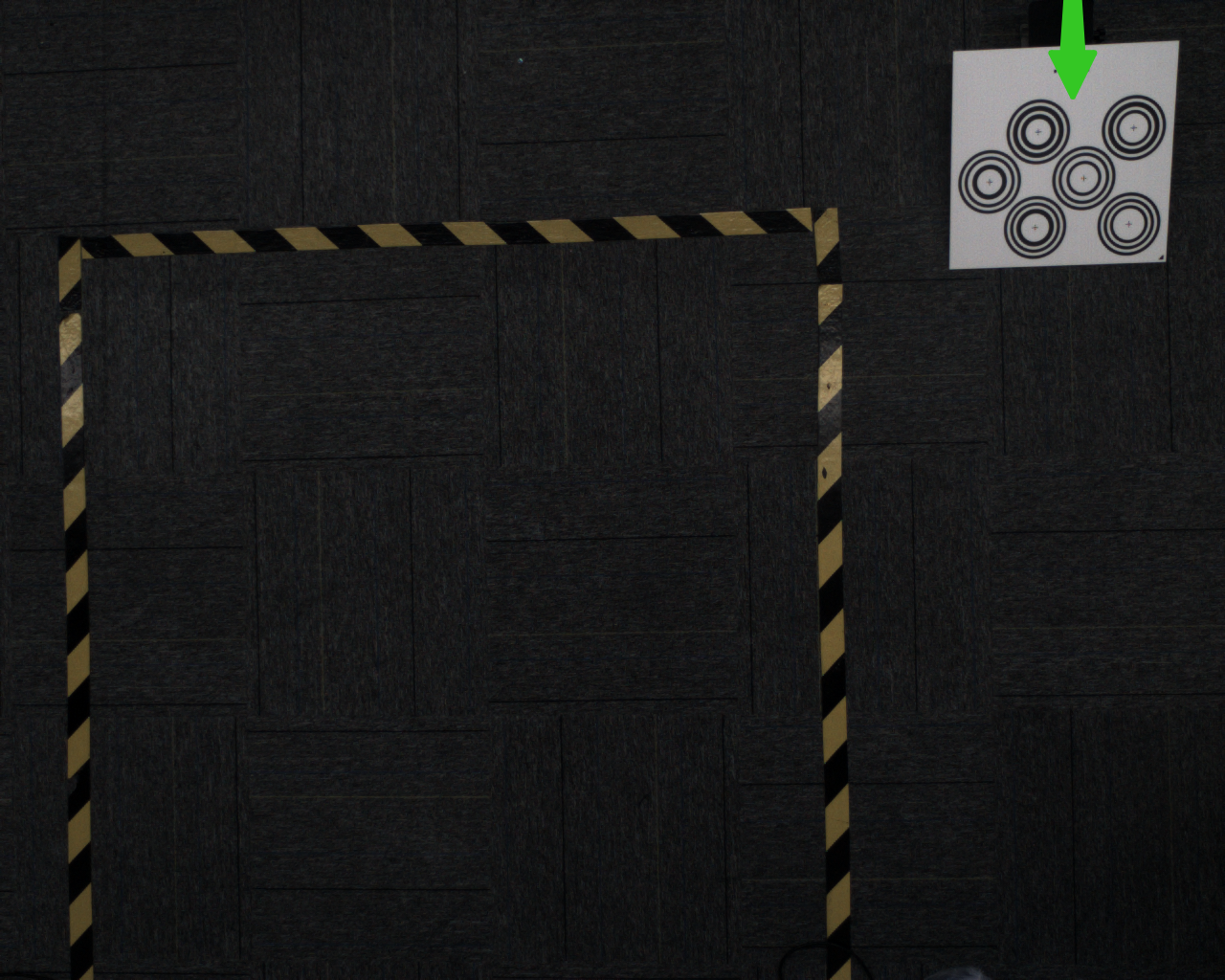
The following image shows calibration board with too large tilt angle, affecting recognition

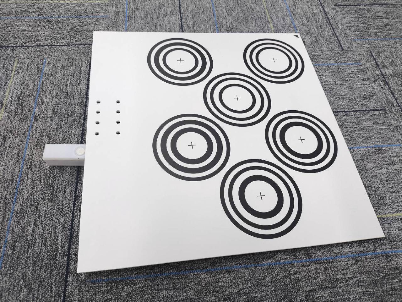
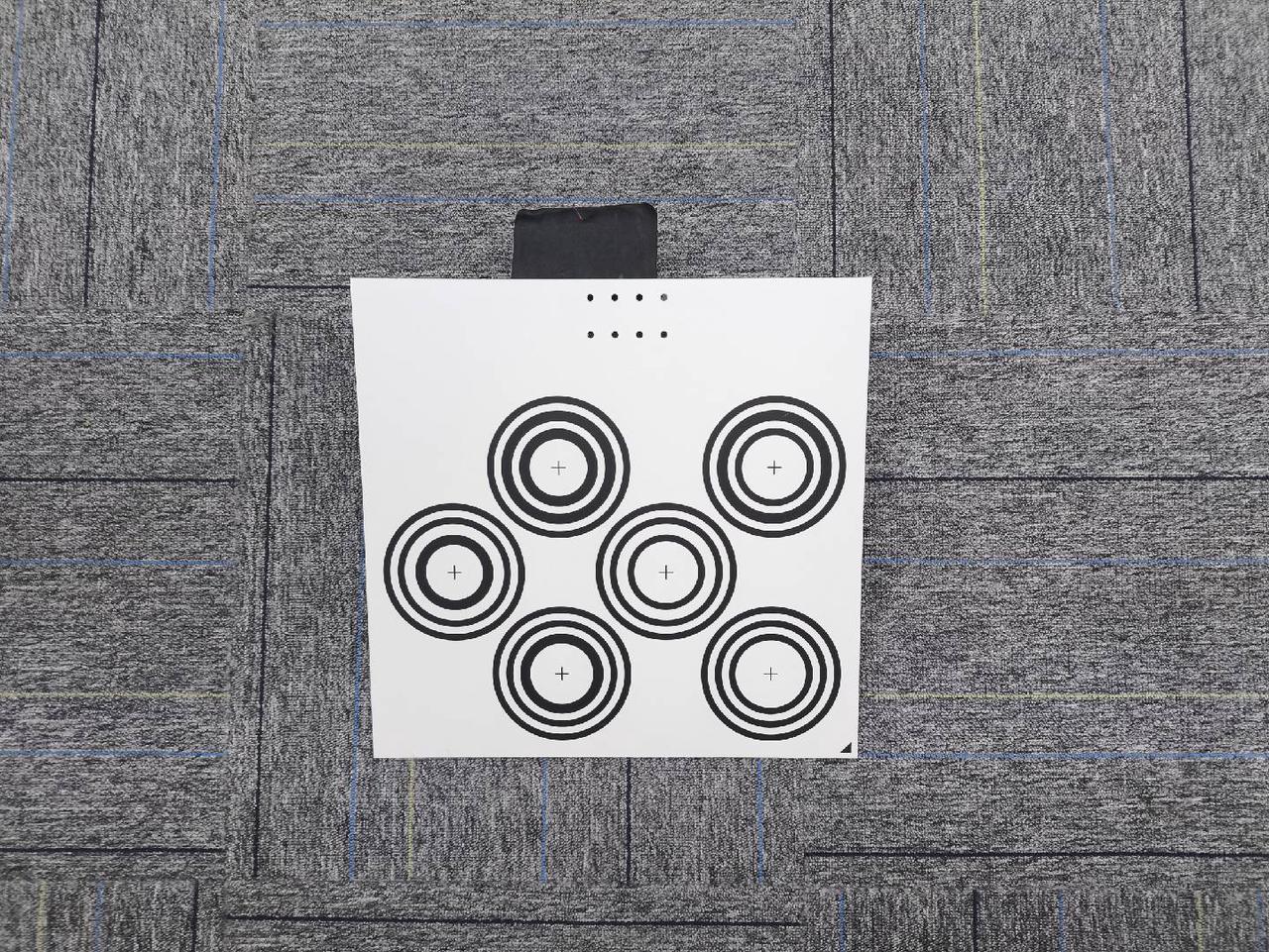
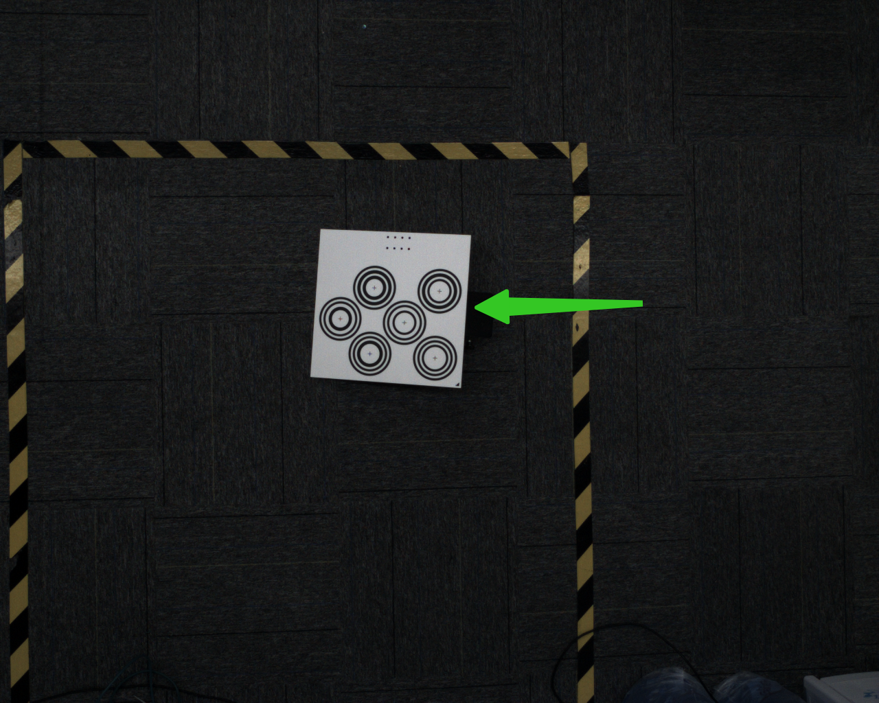
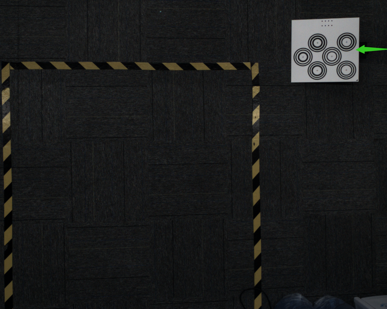
The following image shows calibration board with too small tilt angle, almost no posture change, affecting calibration效果
Correct placement should be at 15-30° for best results


- Error 3: Incorrect Image Brightness and Correct Method
The brightness of calibration board directly affects recognition. Both overexposure and underexposure will impact recognition quality
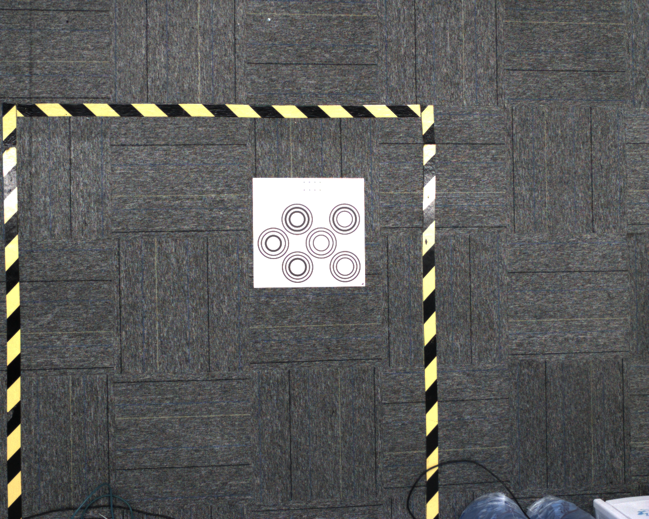
The following image shows overexposed calibration board with large areas of white where pixel values reach 255

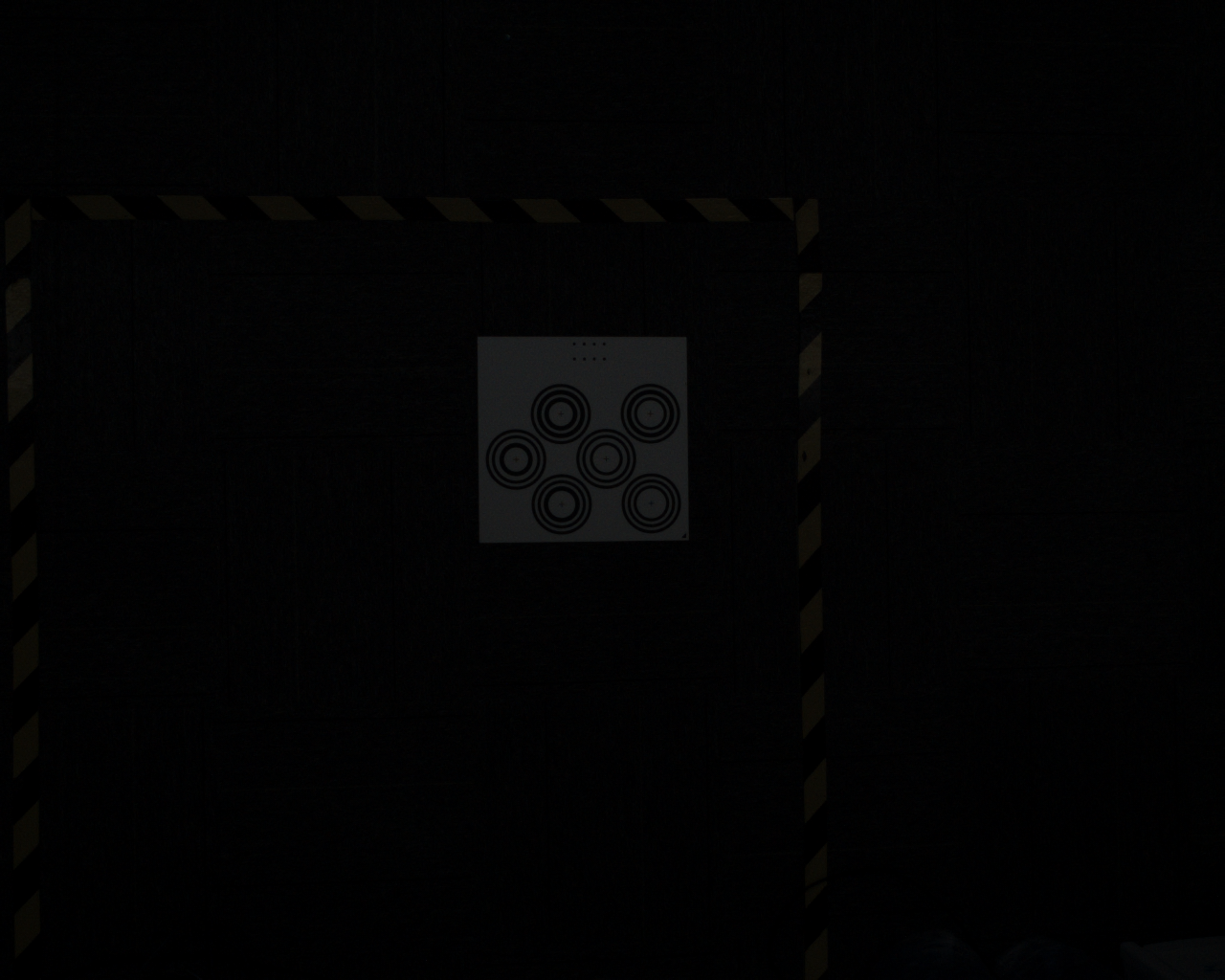
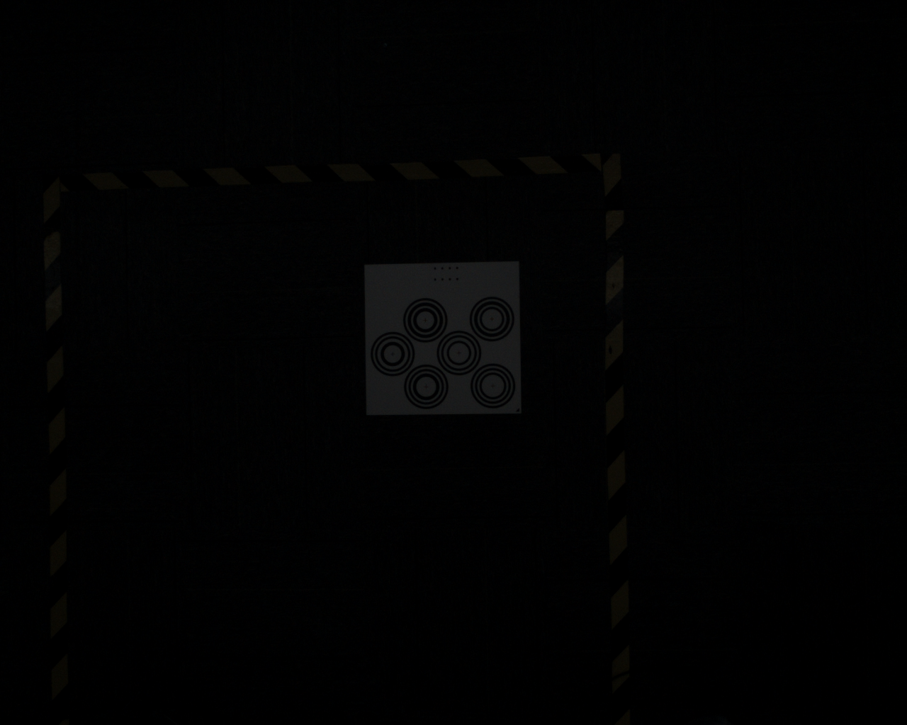
The following image shows underexposed calibration board that is too dark for human eyes to see clearly

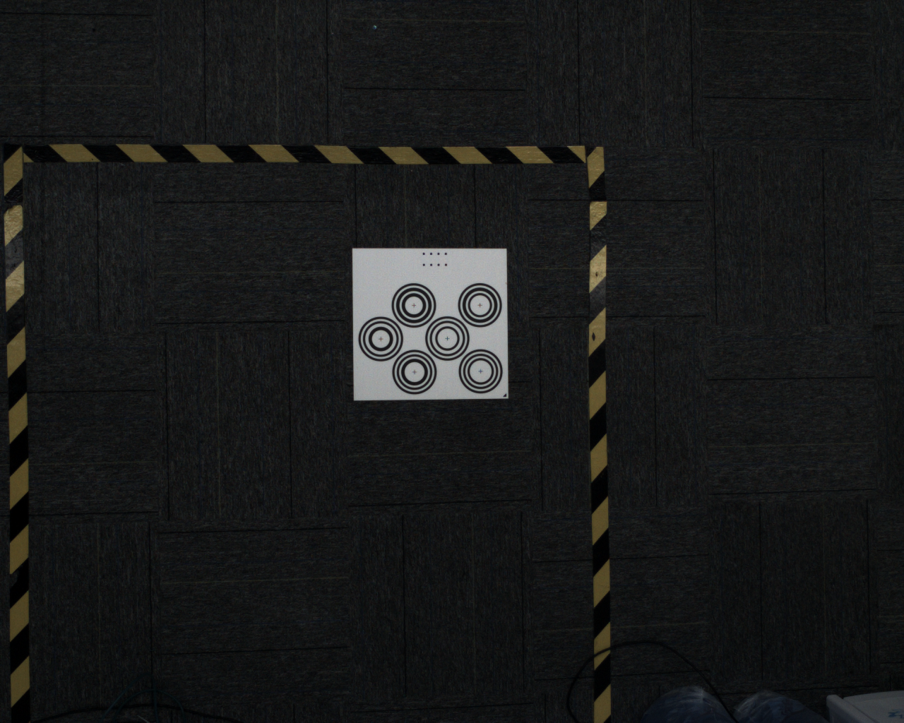
Correct image should be clear, neither overexposed nor underexposed, as shown below
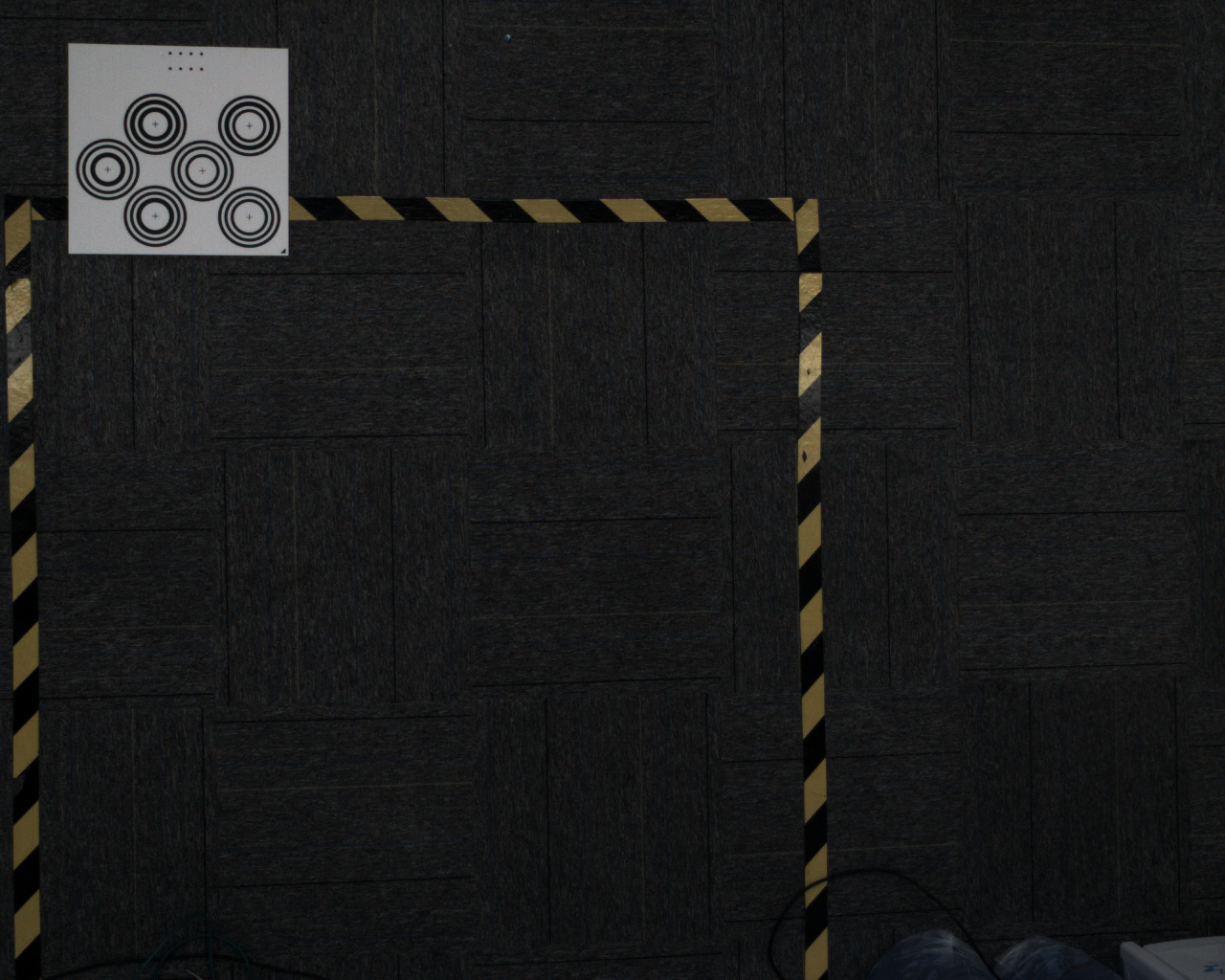
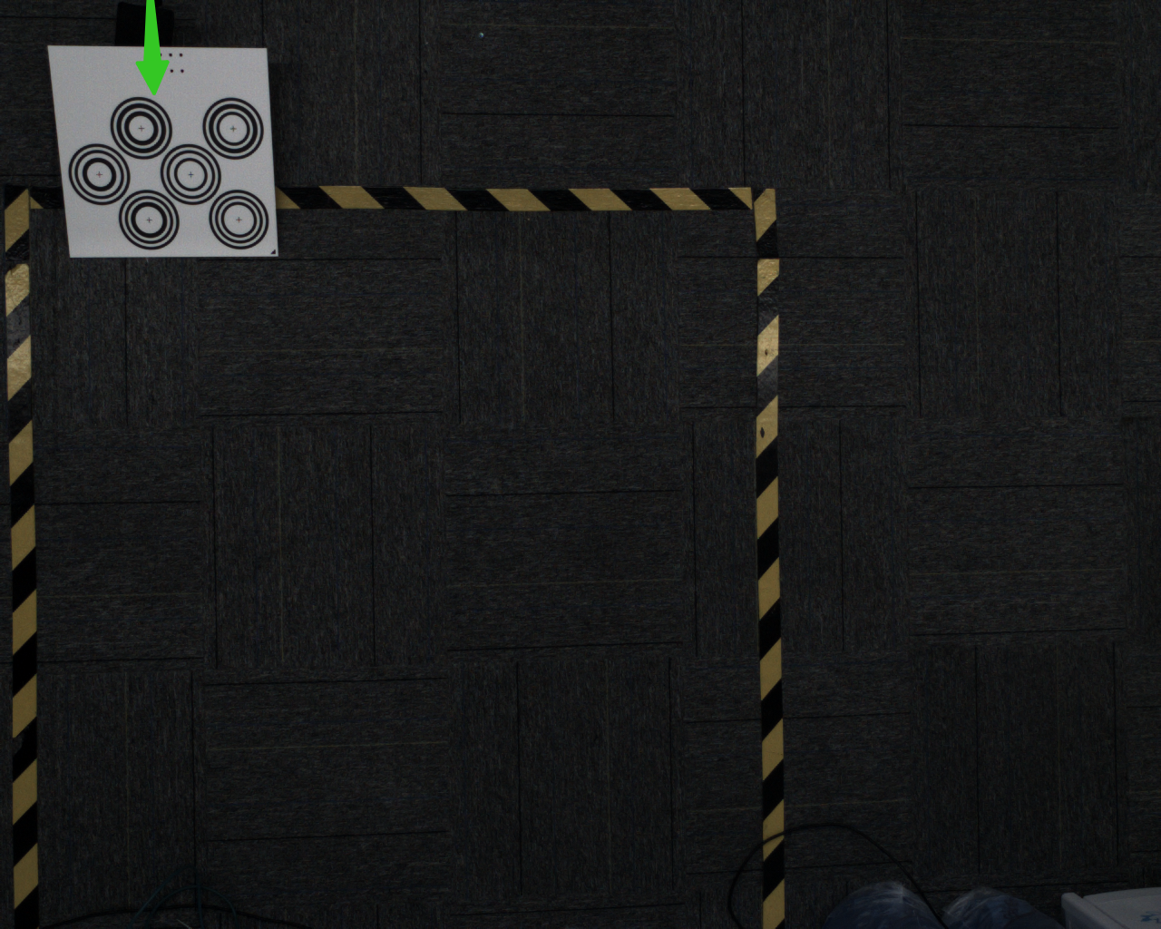
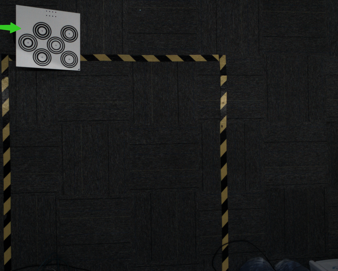
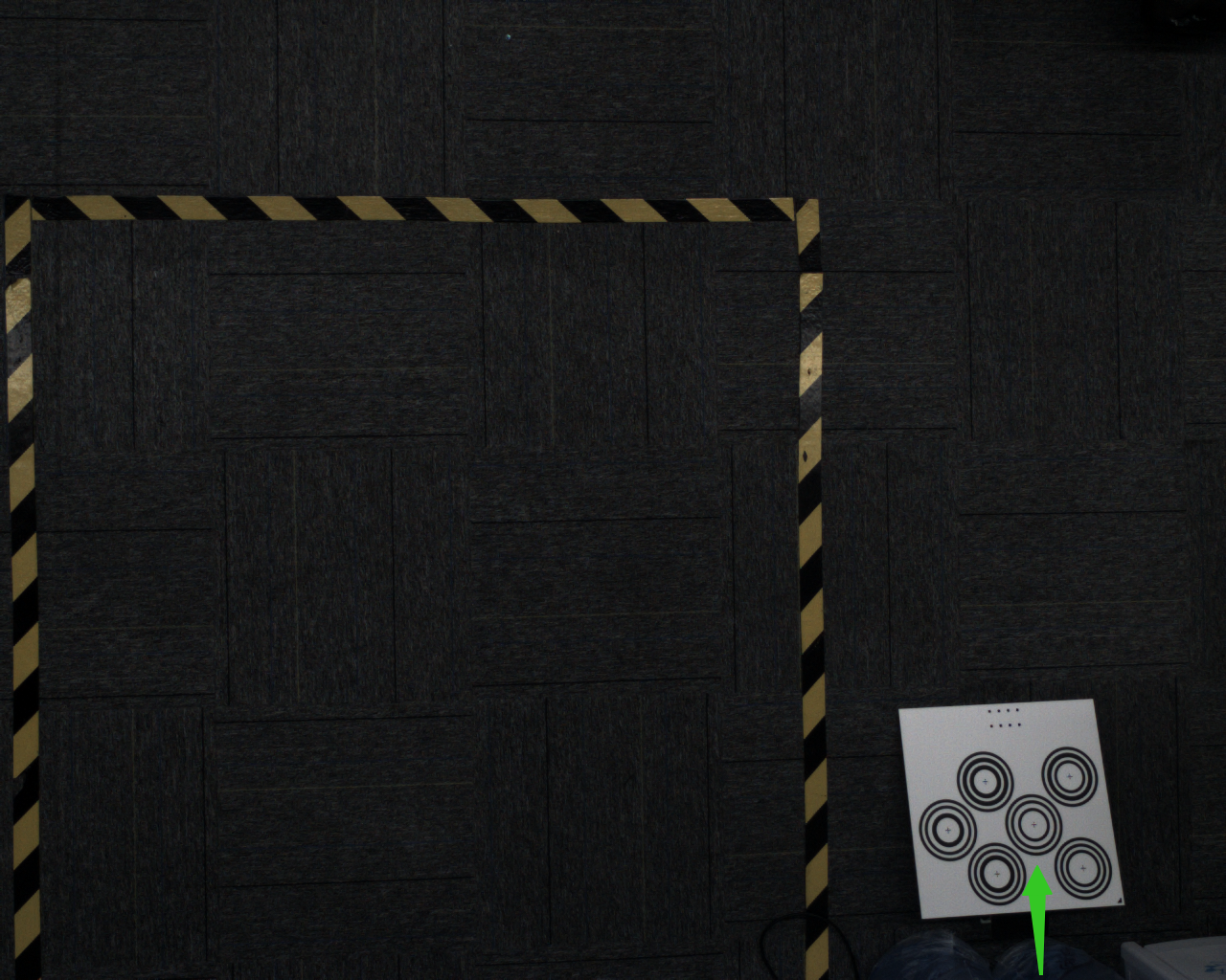
- Error 4: Out of Frame and Correct Method
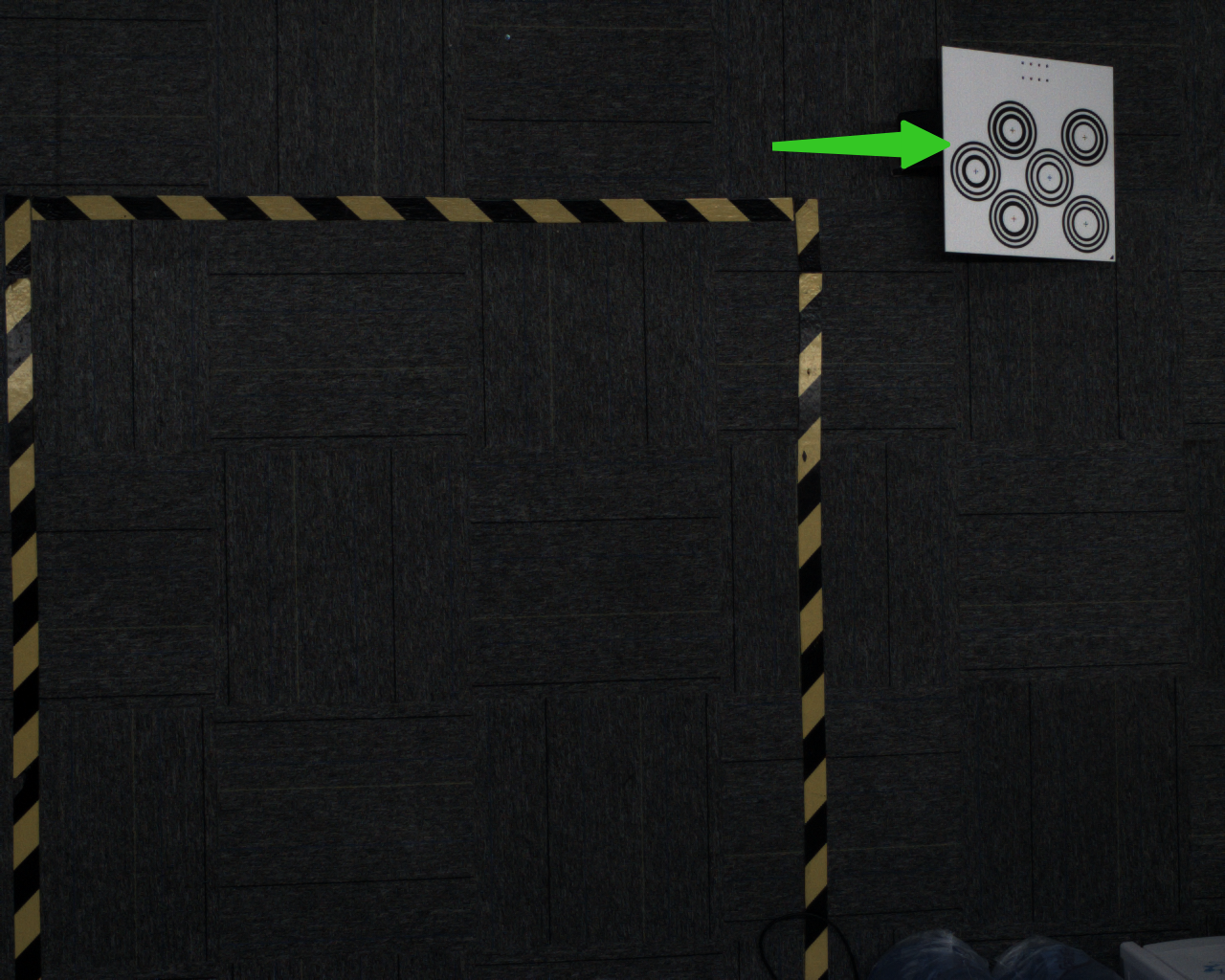
The calibration board is outside the field of view, with incomplete concentric circles, making recognition impossible

- Error 5: Incorrect Calibration Height and Correct Method
For all XEMA D series, calibration height must be strictly controlled within 0.3-0.5m operating range
For all XEMA S series, calibration height must be strictly controlled within 0.5-1m operating range
For all XEMA L series, calibration height must be strictly controlled within 1-2.5m operating range
For all SPARROW series, calibration height must be strictly controlled within 0.3-0.5m operating range
For all FINCH series, calibration height must be strictly controlled within 1.5-3.5m operating range
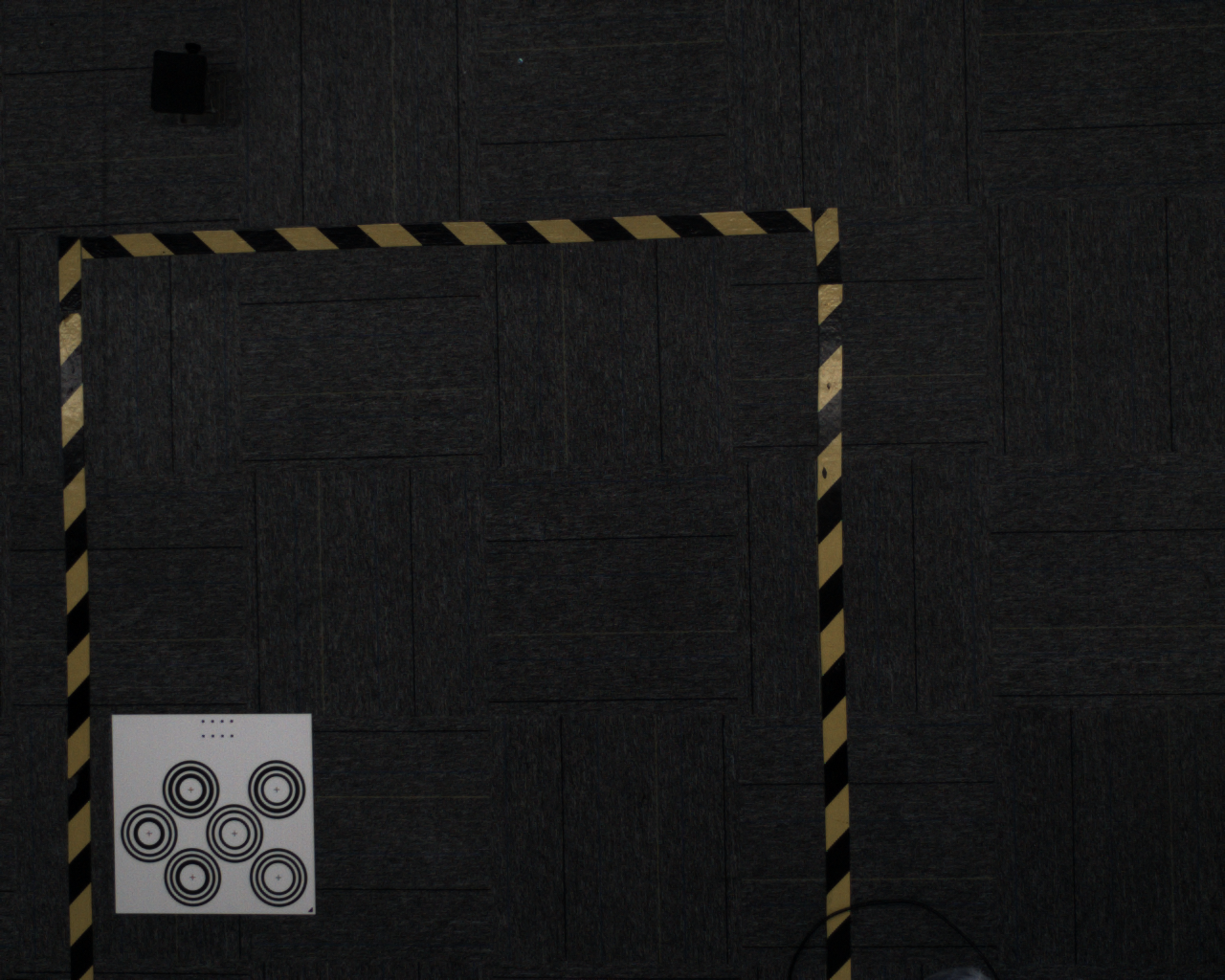
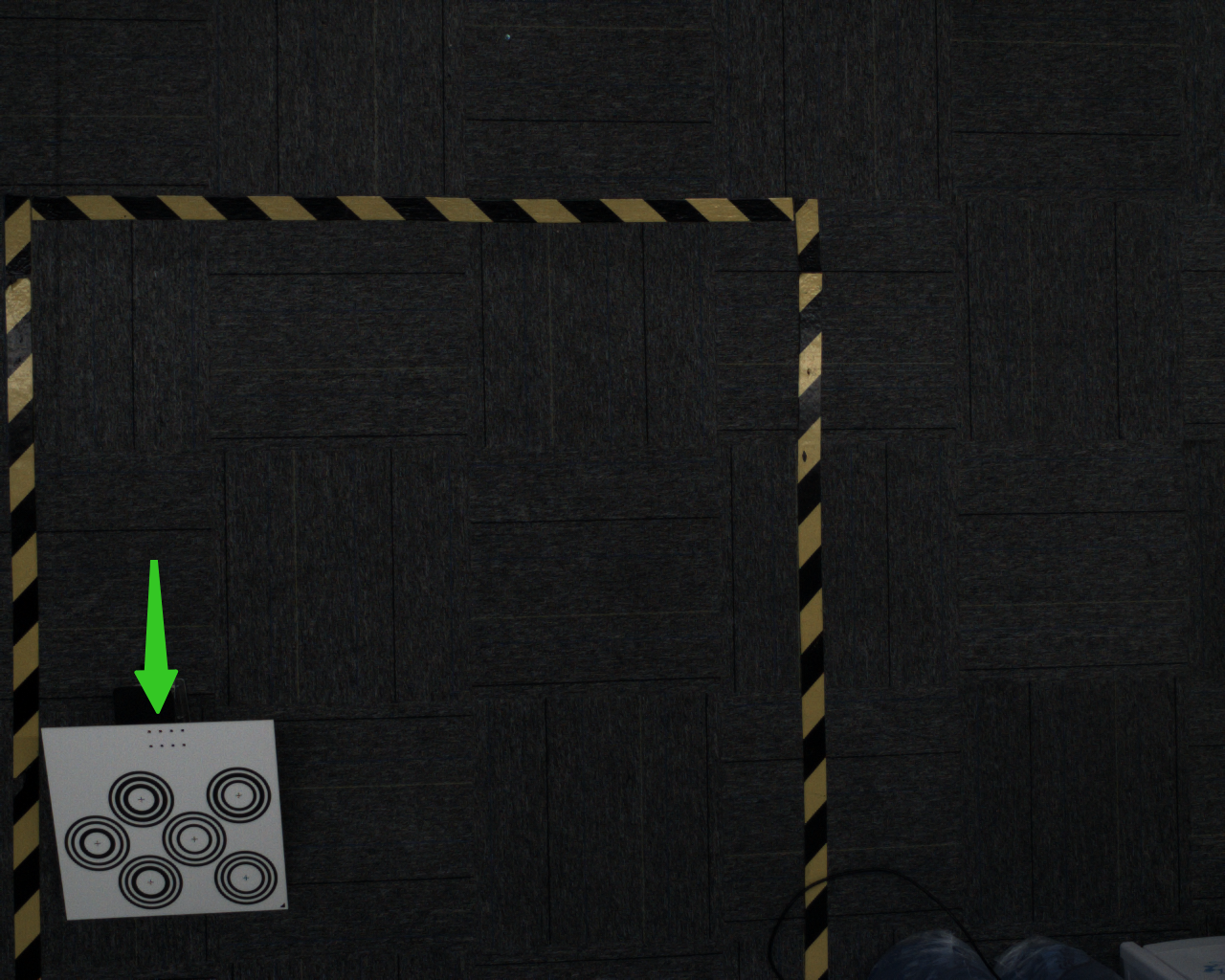
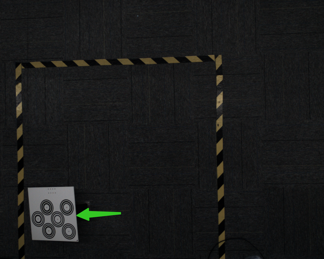
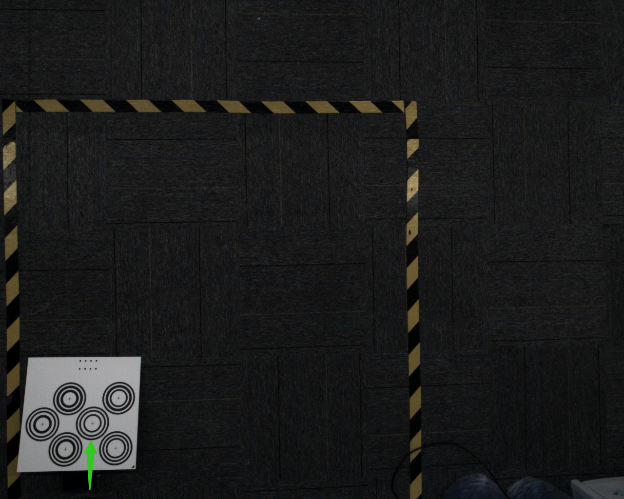
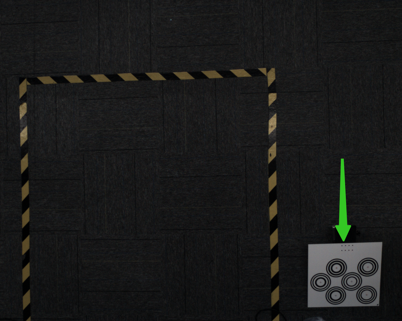
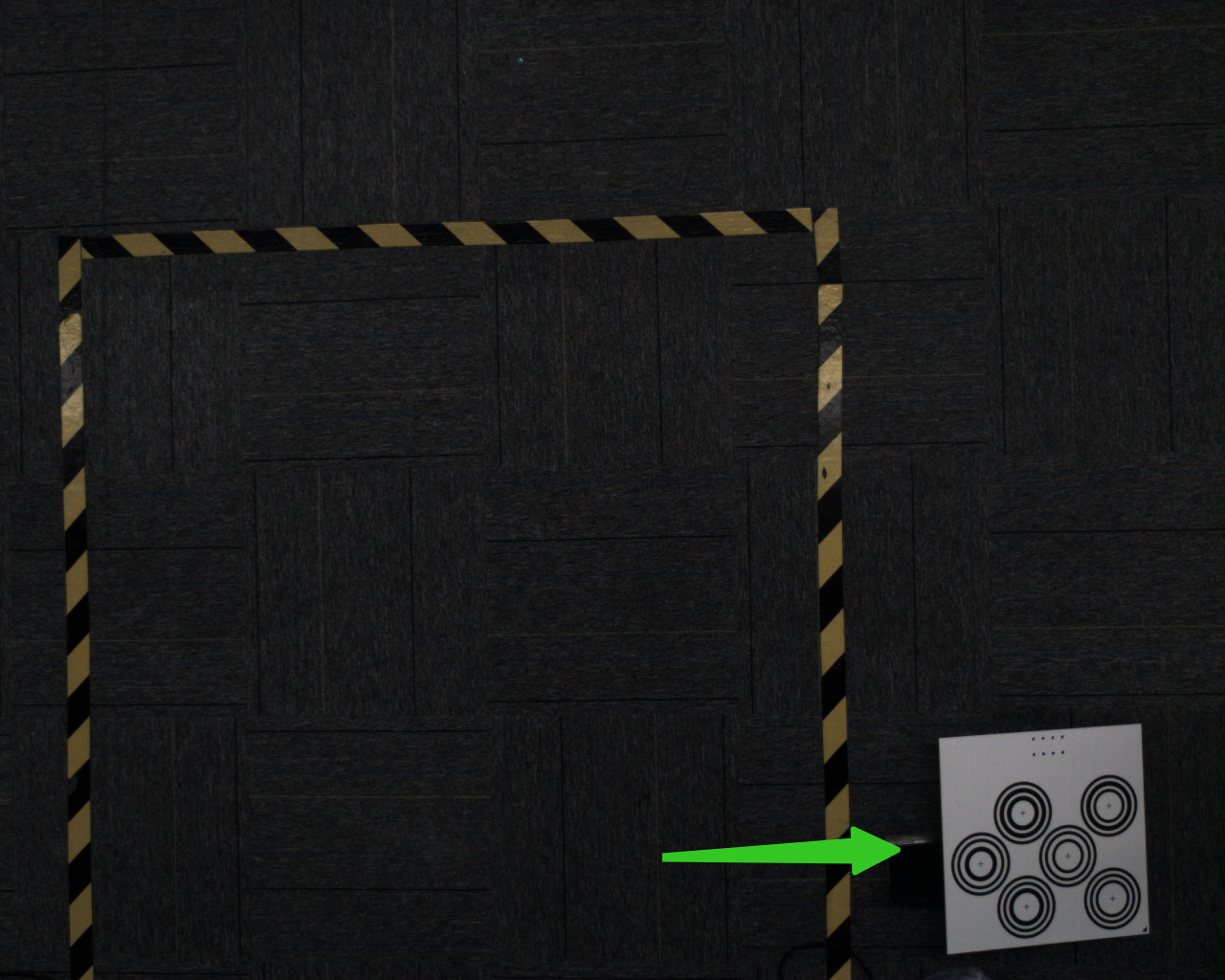
- Error 6: Calibration Board Obstructed by Foreign Objects and Correct Method
Ensure the calibration board image is complete without obstruction or dirt
- Error 7: Blurry Image and Correct Method
Captured calibration images must be clear without blur. Check if the lens is dirty or if the operating range is exceeded
Stereo Cameras
1. Stereo cameras often require extrinsic parameter calibration due to long-term use and transportation interference on-site. We select 25 images for calibration. Too few images may lead to inaccurate calibration parameters. This document provides guidance for both camera calibration and extrinsic parameter calibration.
2. Calibration board size must strictly match the corresponding model for different cameras (matching models will be provided later), otherwise recognition rate will be affected
3. Ensure uniform brightness when capturing calibration board images, no overexposure or underexposure
4. No obvious defocusing during calibration. Calibration must be performed within the operating distance
5. Aperture and focal length of the camera must not change during calibration. Neither the camera nor the calibration board should shake. The video example shows a shaking calibration board - fix it before calibration:
Error Cases and Correct Methods
Error 1 and Correct Method:
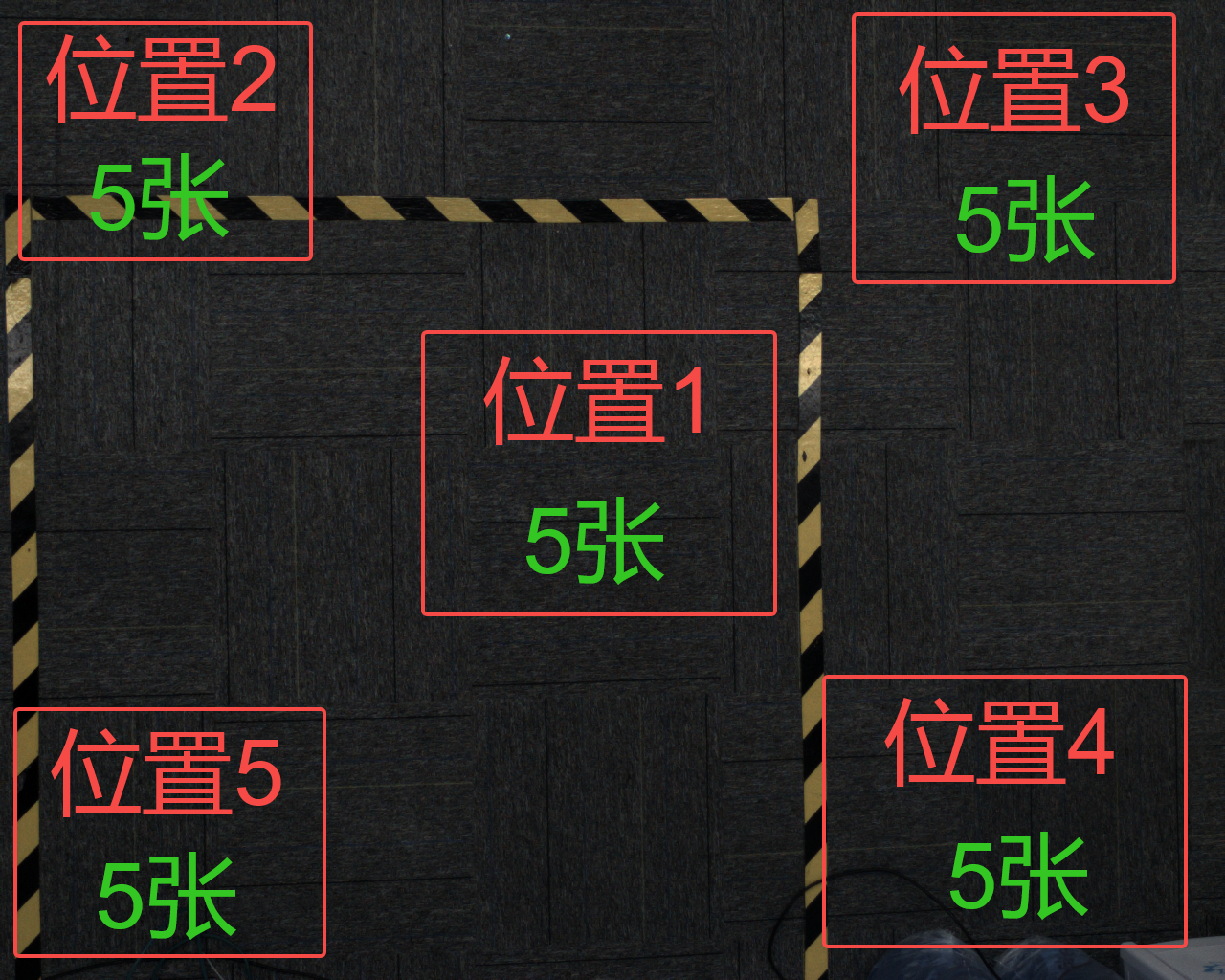
The calibration board placement positions are shown in the schematic: 5 positions total, 5 images per position, 25 images total. The 5 images per position consist of: 1 flat image + 4 images with each edge raised

The following image shows incorrect placement position. Although it's within the field of view, it's too close to the center, not covering the edge areas, which affects calibration accuracy

Correct placement is shown below: close to the edge but not exceeding the field of view of left and right cameras
错误2及正确方法:
标定板摆放角度在15-30°为最优,倾角不可过大,过小
下图标定板摆放倾角过大,影响标定板识别

The following image shows calibration board with too small tilt angle, almost no posture change, affecting calibration quality

正确摆放应在15-30°最佳
错误3及正确方法:
标定板的亮暗也直接影响识别的效果,过曝和过暗都会影响识别的效果
下图为标定板过曝的情况,标定板大面积泛白,像素值已达到255过曝
下图为标定板过暗的情况,标定板很暗,人眼已经无法看清标定板的位置
正确的图像应为下图,清晰不过曝,不过暗

错误4及正确方法:
标定板位置已超出视野内,同心圆不完整,这时更无法识别

采图点位示意图
位置1:平放(1张)+垫四个边(4张)
位置2:平放(1张)+垫四个边(4张)
位置3:平放(1张)+垫四个边(4张)
位置4:平放(1张)+垫四个边(4张)

位置5:平放(1张)+垫四个边(4张)