General Target Visual Parameter Adjustment Guide
This chapter mainly introduces how to adjust the visual parameters according to the actual scene in the orderly loading and unloading, disordered grabbing, and positioning assembly of the general target.
Getting Started:
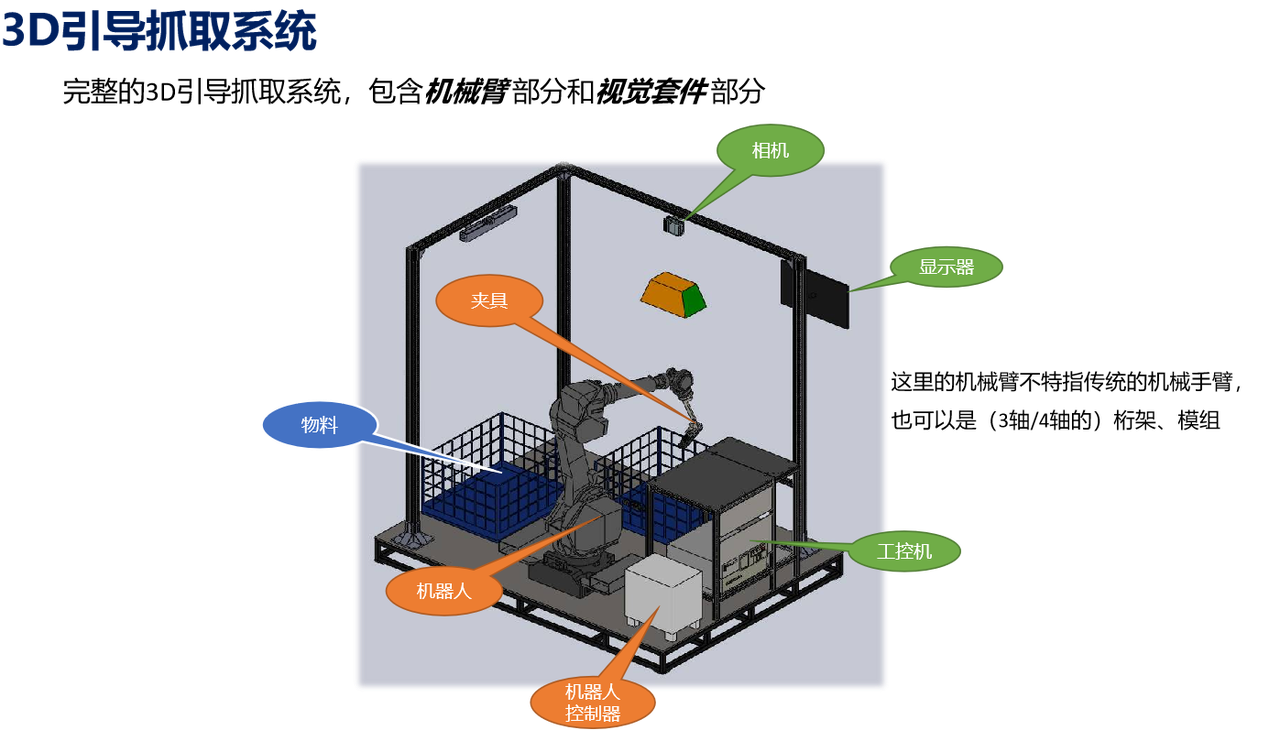
Background introduction
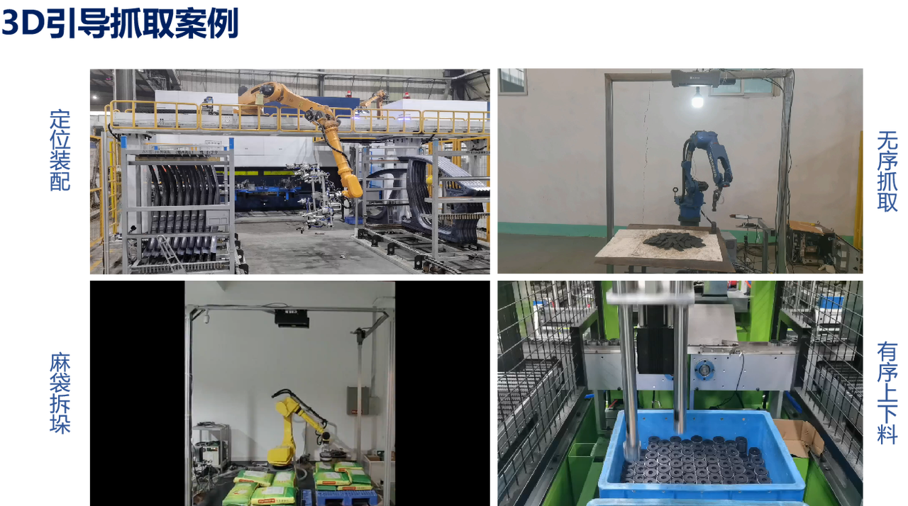
Build project
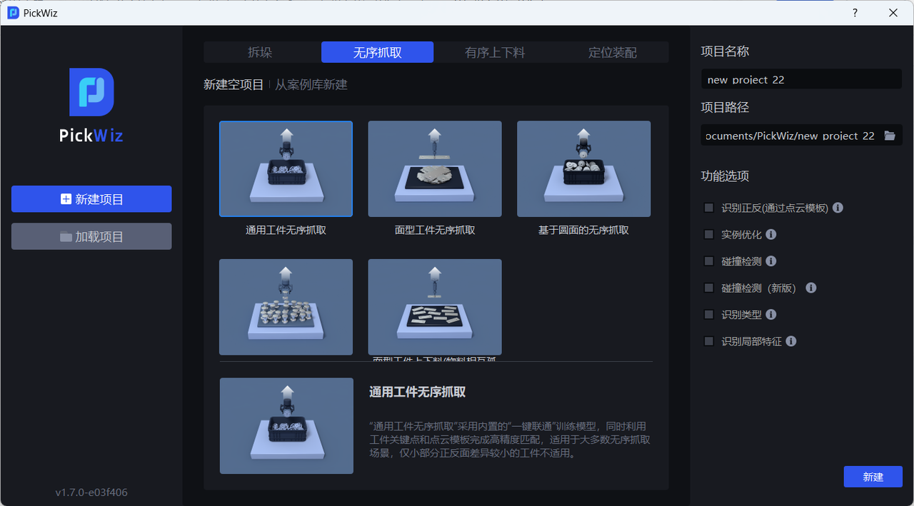
(1) Create a new Loading and unloading of neatly arranged general type target objects/Picking randomly arranged general type target objects/General Target positioned assembly project (the project name and project address can be customized, and the project name cannot contain Chinese characters)
Target type: Universal Target (not a circle, cylinder, or quadrilateral, and the front and back sides are quite different)
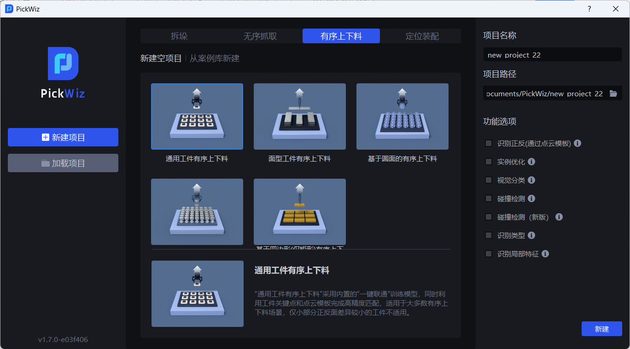
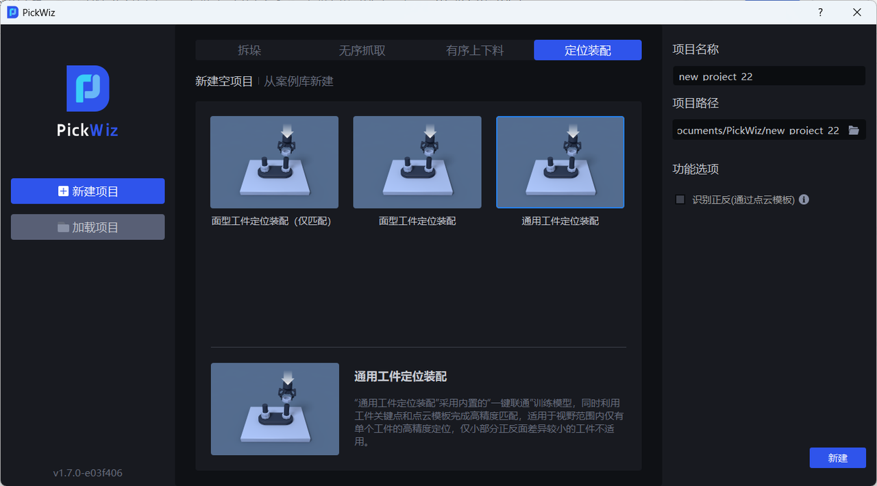
(2) Camera and Robot configuration
(3) Add Target
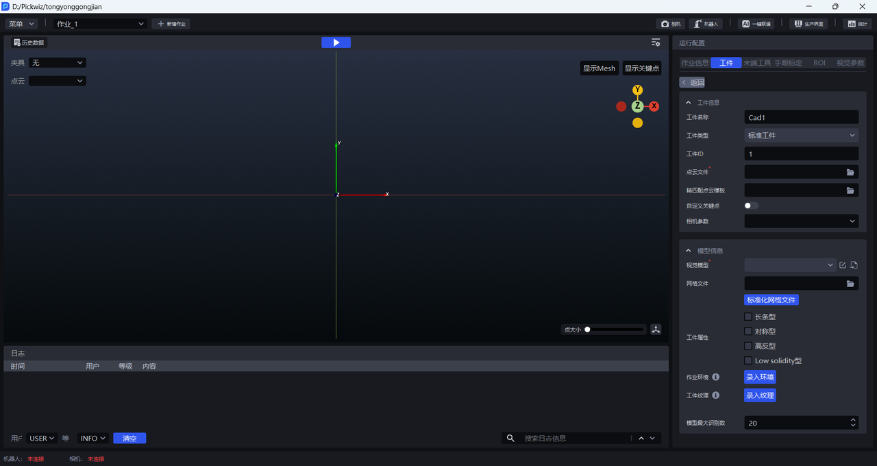
- Target information
The Target name can be customized. The Target type defaults to the standard Target and cannot be changed. The Target ID can be customized and is used to automatically switch the Target when the Robot crawls.
PCD (Point Cloud Data): TargetPoint Cloud, make TargetPoint Cloud in Point Cloud Template Making
Fine matchingPoint Cloud template: used for Fine matching
Custom key points: Universal Target needs to upload the Target’s key point file

CameraParameter: No need to fill in
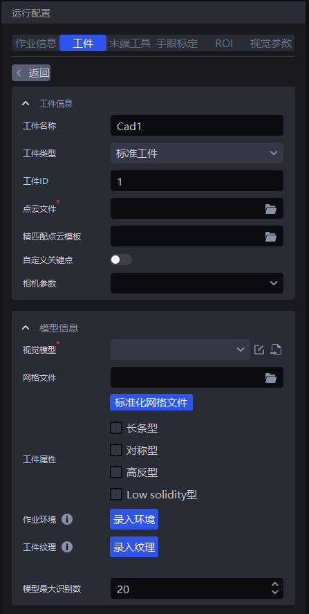
- Model information
Visual Model: The 2D recognition solution for the general Target application is [CAD-based synthetic data training (one-click connection)] (../3D视觉引导方案介绍.md), and the 3D matching solution is [rigid body transformation] (../3D视觉引导方案介绍.md). The Visual Models of different general Target applications need to be trained through one-click connection.
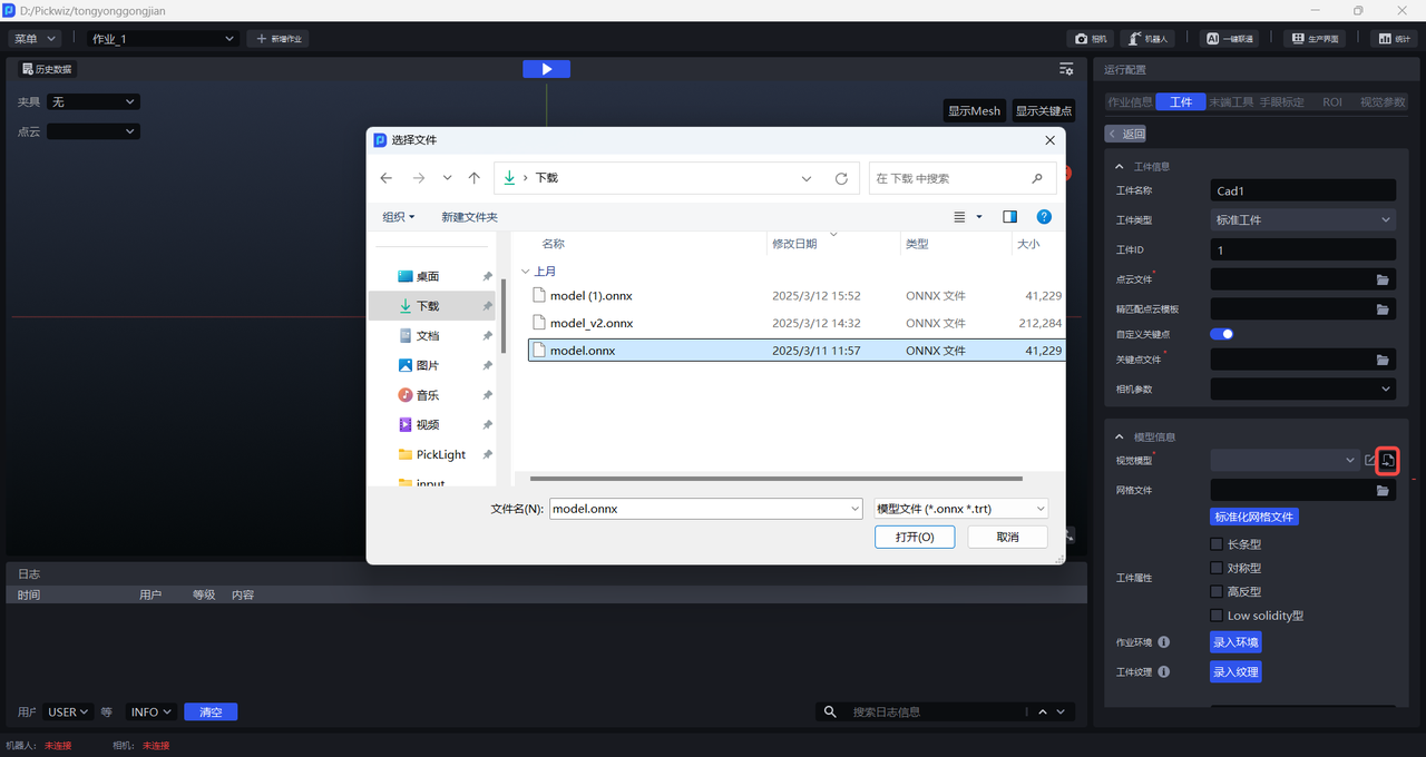
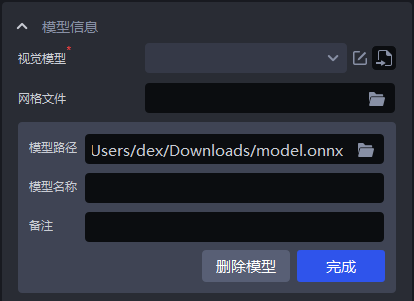
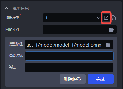
Grid file: Generally upload to TargetCAD. In order to eliminate some noise, a standardized grid file is required. You can also create a **standardized grid file in the **Point Cloud template.
Target attributes: long type, symmetrical type, high reflection type, low solidity type
Task environment: Enter the environment file, and the environment generated by the data in One-click China Unicom will be automatically replaced with the entered environment to improve the recognition effect.
Target texture: Enter the Target texture. When training the model in One-click Connect, the entered Target texture will be used for data enhancement to improve the recognition effect.
Maximum number of model recognitions: Default 20, modified according to scene requirements
- **Pick Point:**Set Pick Point according to Target
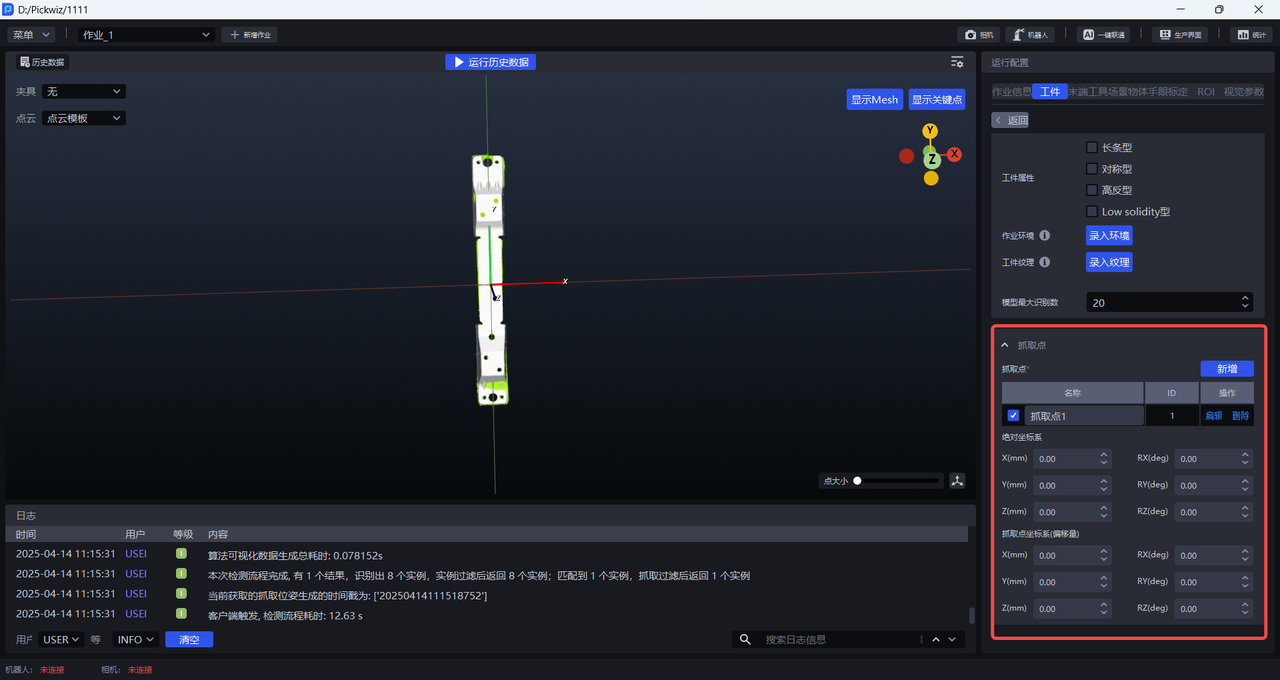
Absolute coordinate system: Take the initial point as the origin, which is provided by TargetPoint Cloud and CAD.
Pick Point coordinate system (offset): Take the current Pick Point as the origin.
(4) Add End-effector, Eye-hand calibration, and ROI
(5) Optional function options: Instance Optimization, collision detection, collision detection (new version), visual classification, Type Identification, Front-Back Identification (via Point Cloud template), Local Identification
Instance Optimization: Optimize the instances generated by the model and process the instance masks.
Collision detection (new version): The collision detection function is used to detect the collision between End-effector and container, and filter grabbing gestures that may collide. Collision Detection Usage Guide
Visual classification: used to identify different textures, different orientations and other features of the same Target. Visual Classification User Guide
Type Identification: Used to identify multiple types of Targets. Type Identification User Guide
Local Identification: Locate the Target through the Target's local characteristics. Local Identification User Guide
Front-Back Identification (via Point Cloud template): You can import the Point Cloud templates of the front and back sides of the Target to match and capture the front or back sides of the Target, and you can set Pick Points for the front or back sides of the Target respectively. Front-Back Identification (via Point Cloud Template) Usage Guide
(6) Test data (historical data is provided for subsequent exercises. You can use the {=tex}2D image and 3DPoint Cloud in the foreground\input folder in the historical data instead of Camera to configure the ROI)
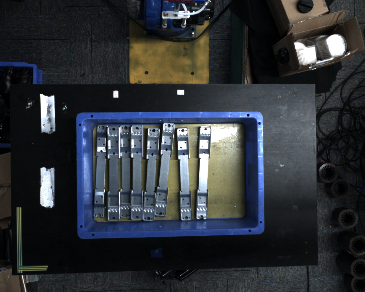
Visual Parameter
- 2D recognition: recognize and segment instances from the actual scene
Preprocessing: Before performing Instance Segmentation, process the 2D image (commonly used: filling the depth image hole & edge enhancement & extracting the top texture & removing the picture background outside of roi3d)
Instance Segmentation: Split the instance (scaling ratio & Confidence lower limit Threshold & automatic enhancement), acceleration can be unchecked Return mask
Point Cloud generation: The way to generate instance Point Cloud, use segmented instance mask or bounding box to generate instance Point Cloud/use filtered instance mask or bounding box to generate instance Point Cloud
Instance filtering: Filter the split instances
Instance sorting: Sort instances
- 3D calculation: Calculate the posture of the instance in the Camera coordinate system and generate Pick Point
Preprocessing: Preprocess 3DPoint Cloud before calculating Pick Point
Attitude estimation: Calculate the attitude of the instance in the Camera coordinate system (Coarse Matching, Fine matching) and generate Pick Point
- Pick Point processing: filter, adjust, and sort Pick Points
Pick Point filtering: Filter Pick Points
Pick Point adjustment: Adjust Pick Point
Pick Point Sorting: Sort Pick Points
1. 2D recognition
This section mainly explains and provides parameter adjustment suggestions for preprocessing, instance segmentation, instance filtering, and instance sorting related functions that affect 2D image recognition results.
1.1 Pretreatment
The preprocessing of 2D recognition is to process the 2D image before Instance Segmentation
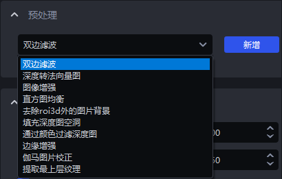
1.1.1 bilateral filtering
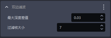
- Function
Image smoothing function based on bilateral filtering
- Parameter description * *
| Parameter | Description | Default value | value range |
|---|---|---|---|
| Maximum depth difference | Maximum depth difference for bilateral filtering | 0.03 | [0.01, 1] |
| filter core size | Bilateral filtering convolution kernel size | 7 | [1, 3000] |
1.1.2 depth to normal vector diagram

- Function
Calculate the pixel normal vector through the Depth image and convert the image into a Normal vector diagram
1.1.3 Image Enhancement
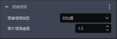
- Function
Commonly used image enhancements, such as color saturation, contrast, brightness, and sharpness
- Parameter description * *
| Parameter | Description | Default value | value range |
|---|---|---|---|
| Image enhancement type | Enhance an element of the image | Contrast | Color saturation, contrast, brightness, sharpness |
| picture enhancementThreshold | How much does enhance a certain element of the image | 1.5 | [0.1, 100] |
1.1.4 Histogram equalization

- Function
Improve image contrast
- Parameter description * *
| Parameter | Description | Default value | value range |
|---|---|---|---|
| local mode | Local or global histogram equalization. If checked, the local histogram will be equalized. If unchecked, the global histogram will be equalized. | Check | / |
| Contrast Threshold | Contrast Threshold | 3 | [1,1000] |
1.1.5 Filter Depth image by color
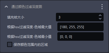
- Function
Filter Depth image based on color value
- Parameter description * *
| Parameter | Description | Default value | value range |
|---|---|---|---|
| padding core size | color fill size | 3 | [1,99] |
| Filter Depth by hsv - Gamut Max | Maximum color value | [180,255,255] | [[0,0,0],[255,255,255]] |
| filter depth according to hsv - color gamut minimum | minimum color value | [0,0,0] | [[0,0,0],[255,255,255]] |
| saves the area within the color range | If checked, the area within the color range will be saved. If not checked, the area outside the color range will be saved. | / | / |
1.1.6 Gamma picture correction
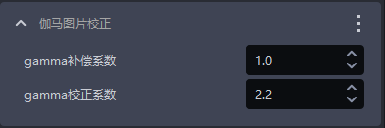
- Function
Gamma correction changes picture brightness
- Parameter description * *
| Parameter | Description | Default value | value range |
|---|---|---|---|
| gamma compensation coefficient | The value of is less than 1, the value of the picture becomes darker, the value is greater than 1, the picture variable | 1 | [0.1,100] |
| gamma correction coefficient | If the value is less than 1, the picture becomes darker, which is suitable for pictures with too high brightness. If the value is greater than 1, the picture becomes brighter, which is suitable for pictures with too low brightness. | 2.2 | [0.1,100] |
1.1.7 fills the Depth image hole
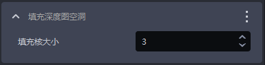
- Function
Fill the hole area in the Depth image and smooth the filled Depth image
- Use Scene
Due to problems such as structural occlusion and uneven lighting of the Target itself, the Depth image may be missing some areas of the Target.
- Parameter description * *
| Parameter | Description | Default value | value range |
|---|---|---|---|
| padding core size | Size of hole filling | 3 | [1,99] |
The filling core size can only be filled in with odd numbers
- Adjust parameters
Adjust according to the detection results. If the filling is excessive, the Parameter should be adjusted smaller; if the filling is insufficient, the Parameter should be increased.
- Example
1.1.8 edge enhancement
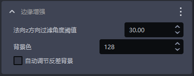
- Function
Set the edge of the texture in the image to the background color or a color that is significantly different from the background color to highlight the edge information of the Target
- Use Scene
Targets block or overlap each other, resulting in unclear edges
- Parameter description * *
| Parameter | Description | Default value | Parameter range | Parameter adjustment recommendation |
|---|---|---|---|---|
| normal z direction filter Threshold | Depth image The angle between the normal vector corresponding to each point and the positive Z-axis direction of the Camera coordinate system is filtered Threshold. If the angle between the normal vector of the point and the positive Z-axis direction of the Camera coordinate system is greater than this Threshold, then the point in the 2D image corresponds to The color of the position will be set to the background color or the color that is significantly different from the background color | 30 | [0,180] | For flat target surfaces, the Threshold can be smaller. For curved target surfaces, the Threshold can be appropriately increased according to the degree of surface inclination. |
| Background color | RGB color of background color Threshold | 128 | [0,255] | |
| Automatically adjust contrast background | check After automatically adjusting the contrast background, set the color of the points in the 2D image with an angle greater than the filter Threshold to a color that is significantly different from the background color . Uncheck Automatically adjust the contrast background, and set the color of the point in the 2D image with an angle greater than the filter Threshold to , the color corresponding to the background color , | Uncheck | / |
- Example
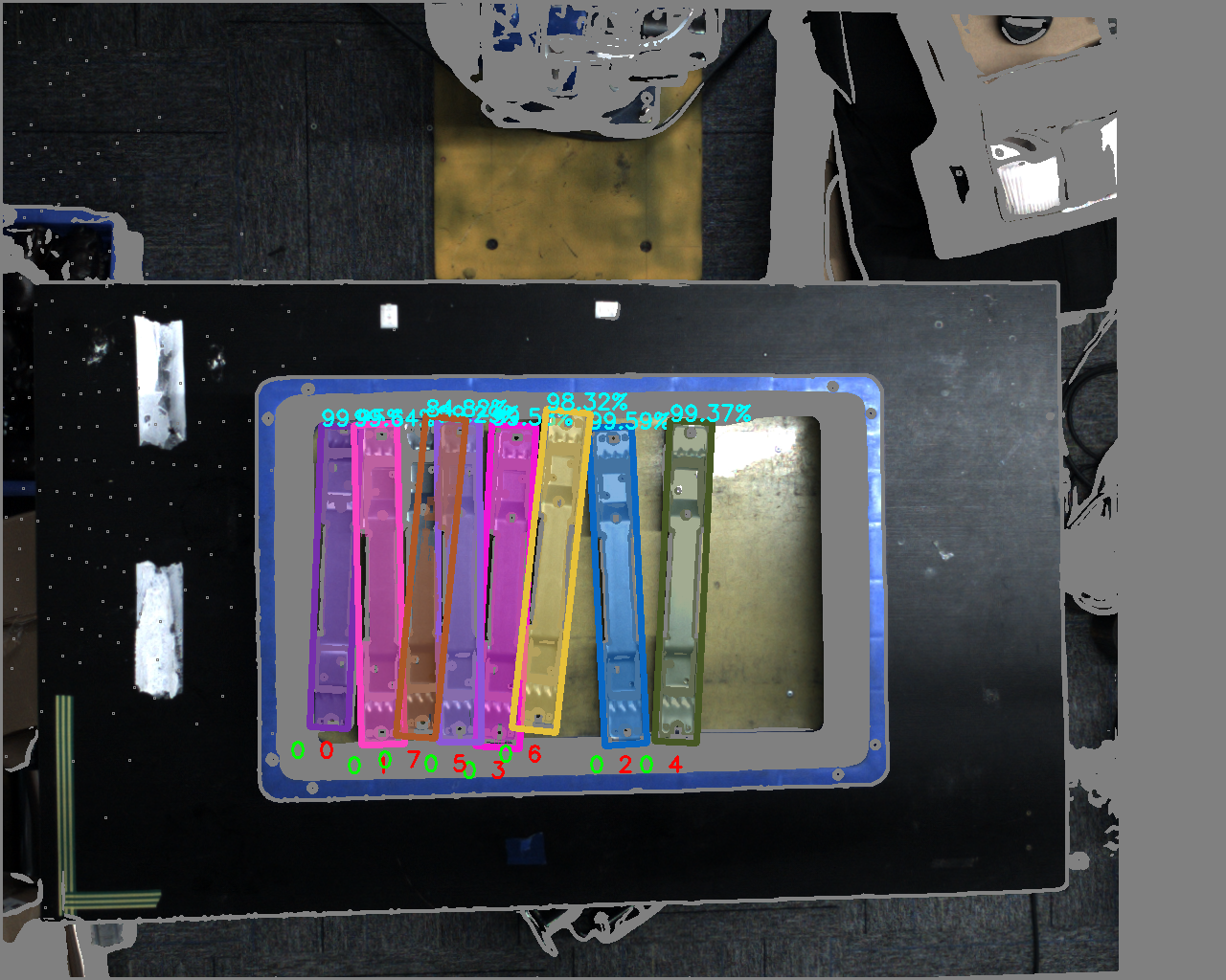
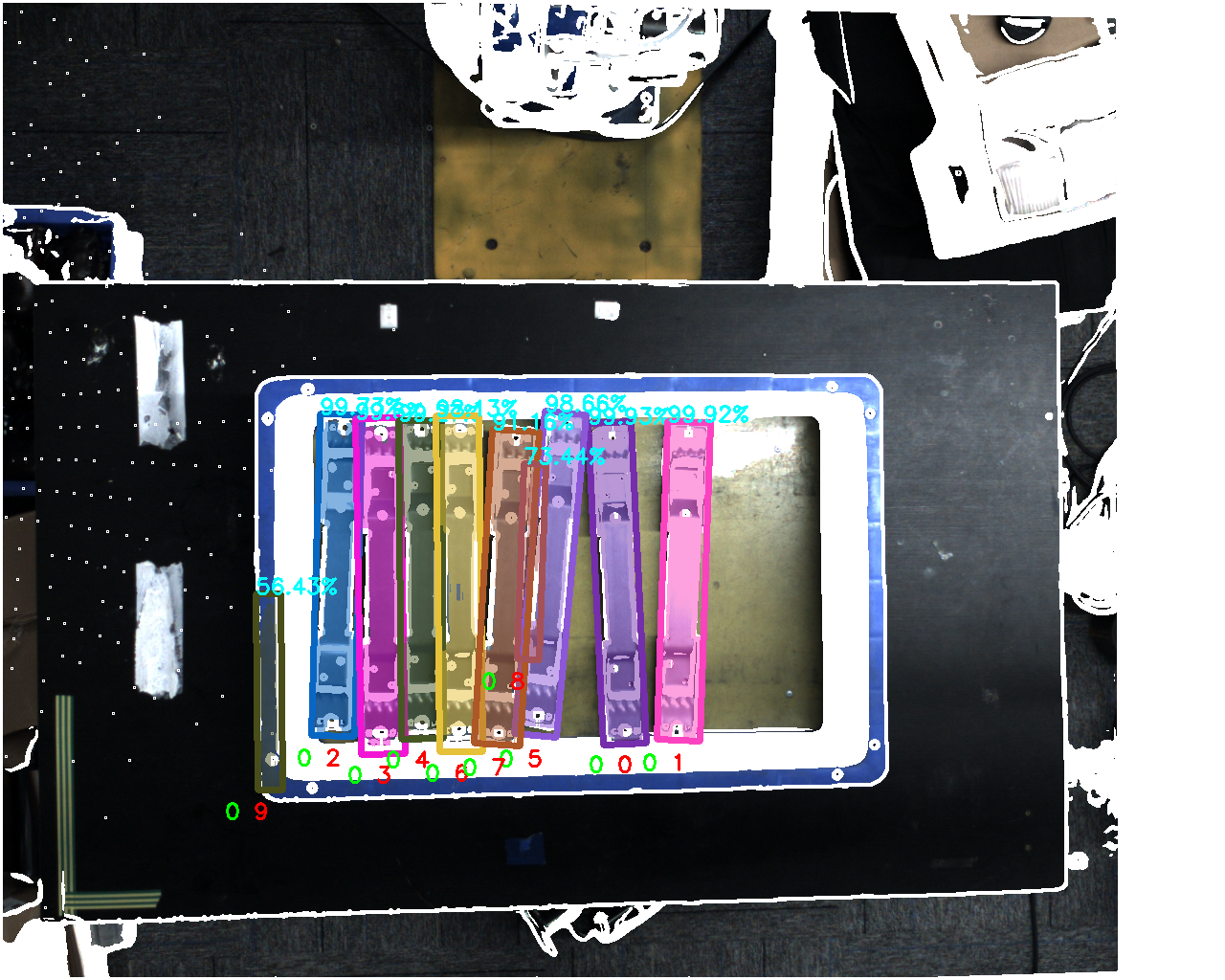
1.1.9 extracts the top texture
- Function
Extract the top or bottom Target texture, and set other areas to the background color or a color that is significantly different from the background color.
- Use Scene
Factors such as poor lighting conditions, similar color and texture, close stacking, staggered stacking, or occlusion may make it difficult for the model to distinguish the texture differences between the upper and lower targets, so it is easy to detect errors.
- Parameter description * *
| Parameter | Description | Default value | Parameter range | unit | Parameter adjustment recommendation |
|---|---|---|---|---|---|
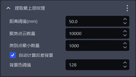
| distance Threshold(mm) | If the distance between point and the uppermost plane (bottom plane) is lower than the Threshold, it is considered to be a point in the uppermost plane (bottom plane) and should be retained. Otherwise, it is considered to be a point in the lower layer (upper layer). The color of the point in the lower layer (upper layer) is set to the background color or a color that is significantly different from the background color | 50 | [0.1, 1000] | mm | is generally adjusted to 1/2 of the Target height |
| Clustering Point Cloud Number | The number of points expected to participate in clustering, the number of sampling Point Clouds in the ROI 3D area | 10000 | [1,10000000] | / | The more the number of clustering Point Clouds |
| Minimum number of category points | Minimum number of points used to filter categories | 1000 | [1, 10000000] | / | / |
| automatically calculates the contrast background | check After automatically calculating the contrast background, set other areas except the top layer (bottom layer) in the 2D image to a color that is significantly different from the background color Threshold. Uncheck Automatically calculate the contrast background, and set other areas except the top layer (bottom layer) in the 2D image to the color corresponding to the background color Threshold | Check | / | / | / |
| Background ColorThreshold | Background ColorRGB ColorThreshold | 128 | [0, 255] | / | / |
- Example
1.1.10 Remove picture background outside roi3d
- Function
Remove the background from the 2D image except the ROI3D area
- Use Scene
Too much background noise in the image affects the detection results
- Parameter description * *
| Parameter name | Description | Default value | value range |
|---|---|---|---|
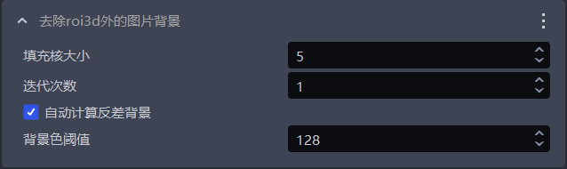
| padding core size | Size of hole filling | 5 | [1,99] |
| Number of iterations | Number of iterations of image expansion | 1 | [1,99] |
| automatically calculates the contrast background | check After automatically calculating the contrast background, set the area outside the roi in the 2D image to a color that is significantly different from the background color Threshold and uncheck it. Automatically calculate the contrast background and set the area outside the roi in the 2D image to the color corresponding to the background color Threshold | Check | / |
| Background ColorThreshold | RGB color of background color Threshold | 128 | [0,255] |
The filling core size can only be filled in with odd numbers
- Adjust parameters
If you need to remove more background noise from the image, you should reduce the fill kernel size
- Example
1.2 Instance Segmentation
1.2.1 scaling
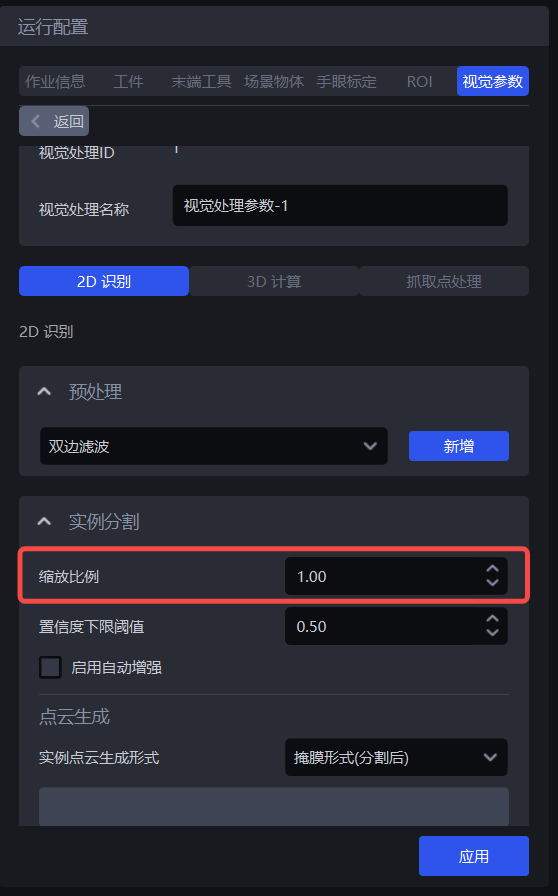
- Function
By scaling the original image proportionally and then inference, the accuracy and recall rate of 2D recognition can be improved.
- Use Scene
This function should be adjusted if the detection results are poor (such as no instances detected, missing recognition, bounding box bounding to multiple instances, or the box is not full of instances).
- Parameter description * *
Default value: 1.0
Value range: [0.01, 3.00]
Step size: 0.01
Adjust parameters
- Run with default values and view the detection results in the visualization window. If instances are not detected, recognition is missed, the bounding box is bounded to multiple instances, or the box is not full of instances, the function should be adjusted.
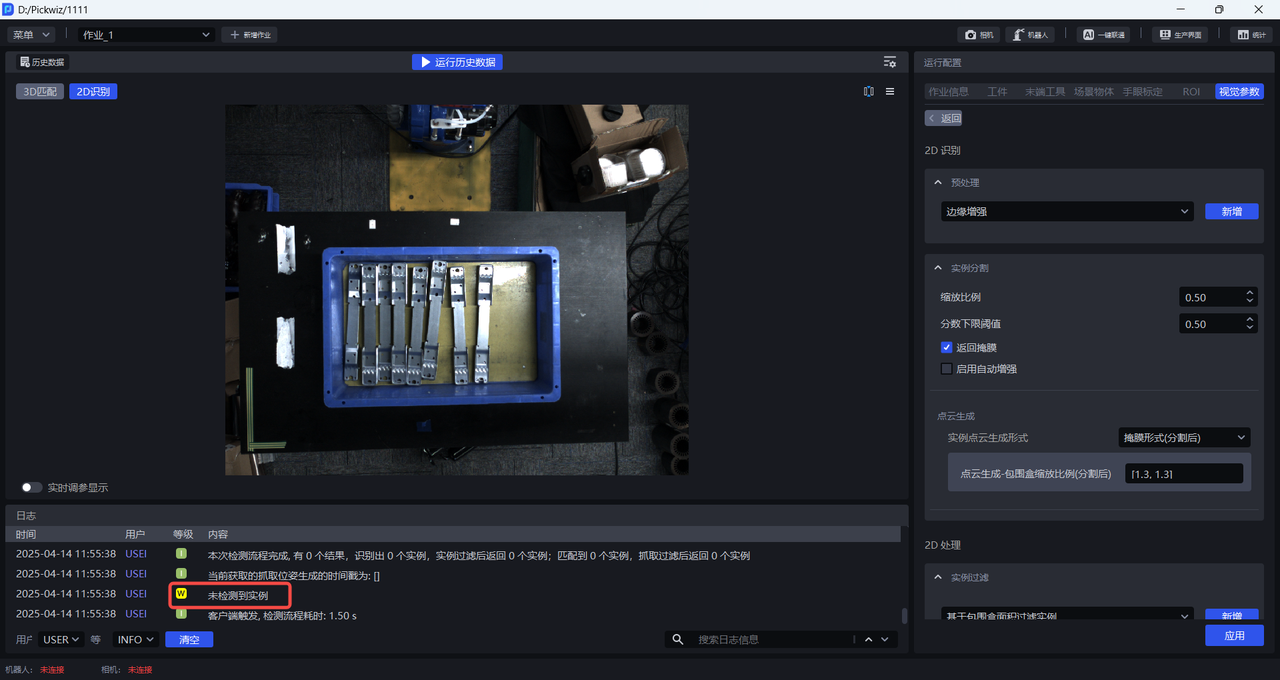
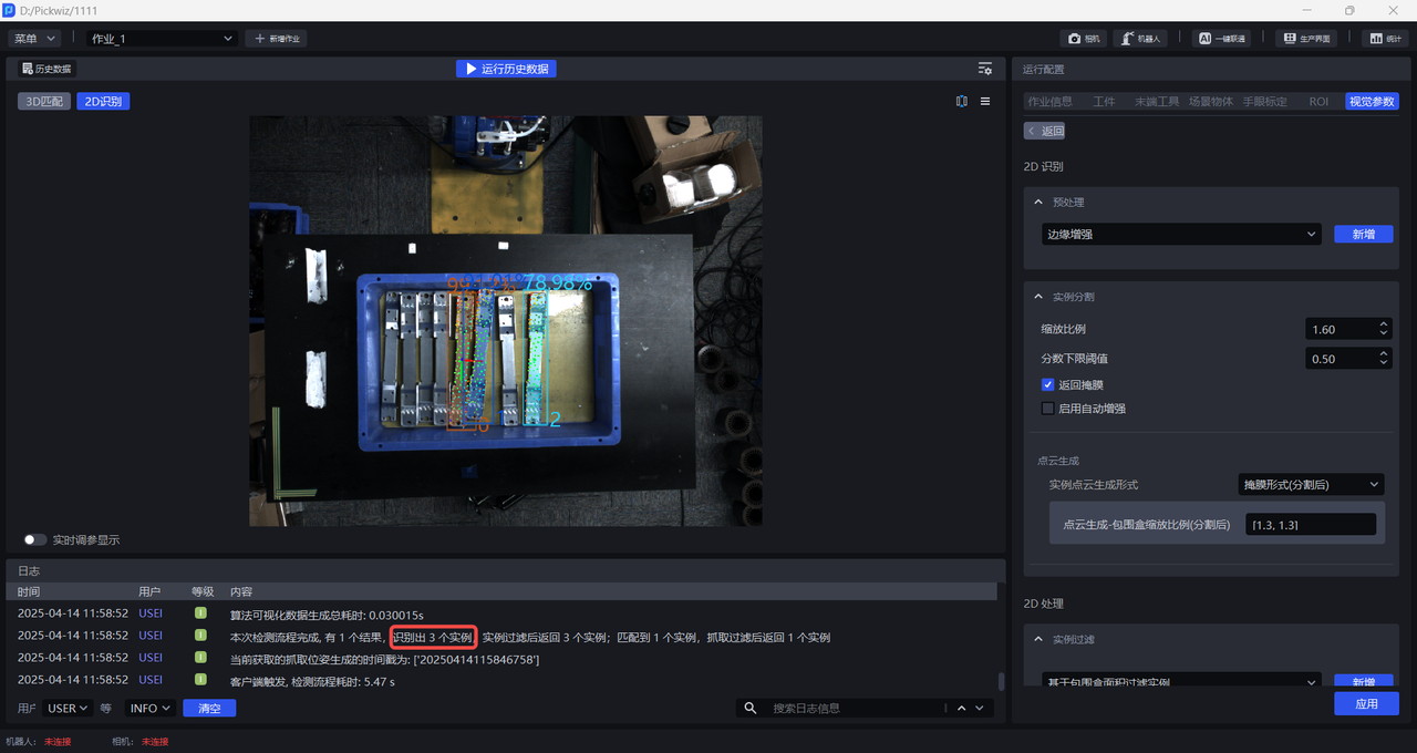
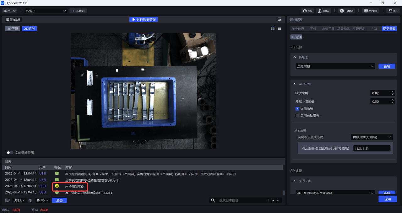
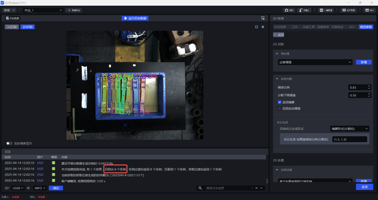
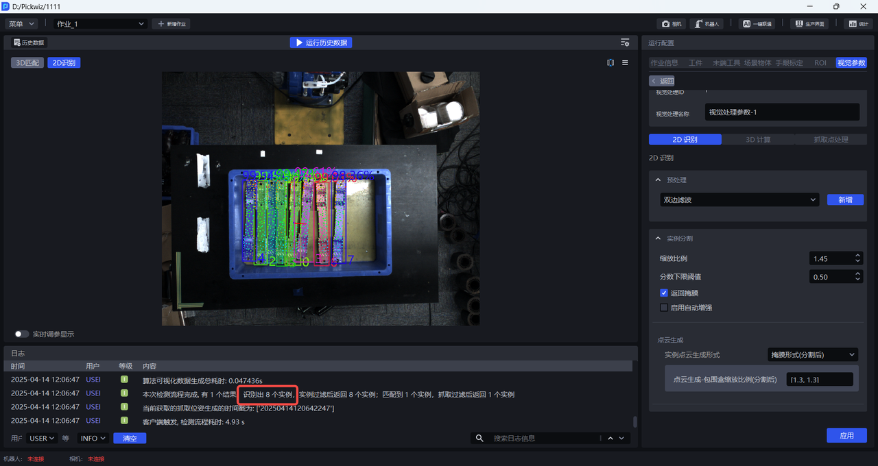
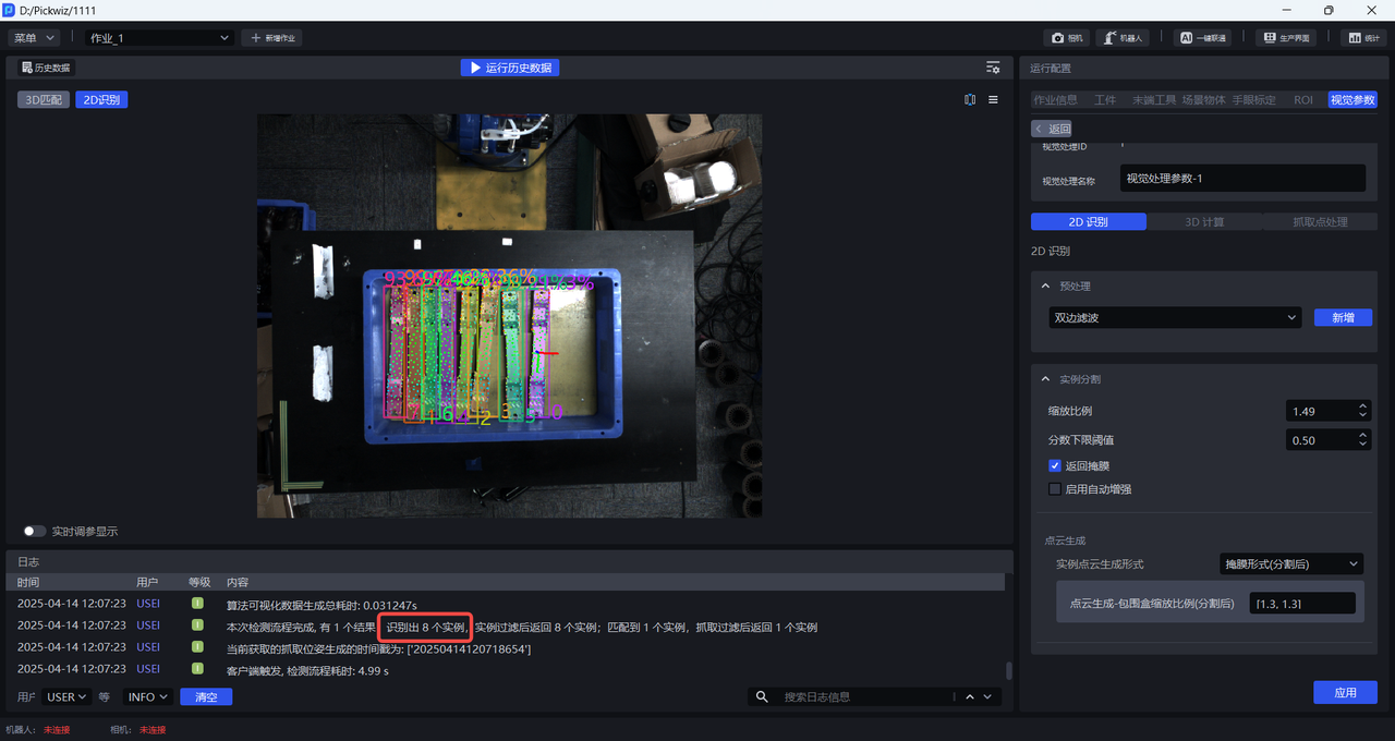
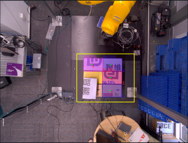
The percentage of instances in 2D recognition is the Confidence score, and the number is the Instance ID (the recognition order of the instances).
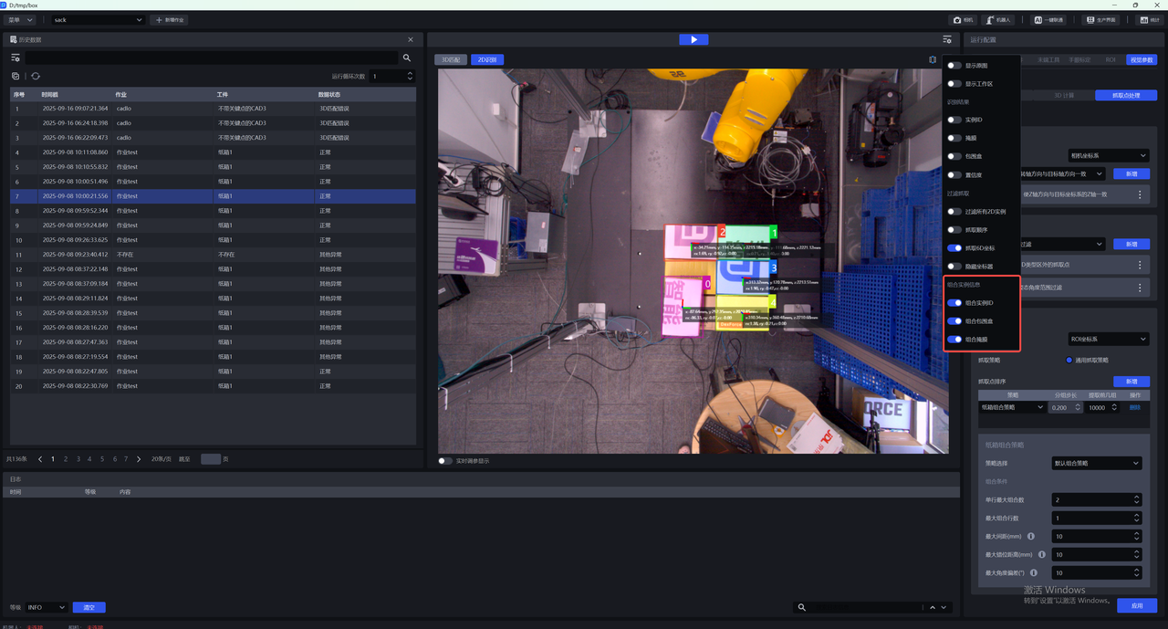
In 2D recognition, the colored shadow on the instance is the mask, the rectangular box surrounding the instance is the bounding box, and the colored points are key points.
As shown in the figure below, the detection results are significantly improved when the scaling ratio is 0.83, so it can be determined that 0.83 is the lower limit of the scaling range.
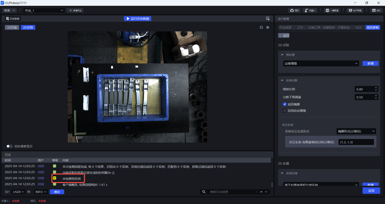
The detection results are significantly reduced when the scaling ratio is 1.5, so it can be determined that 1.5 is the upper limit of the scaling range.
1.2.2 Confidence lower limit Threshold
- Function
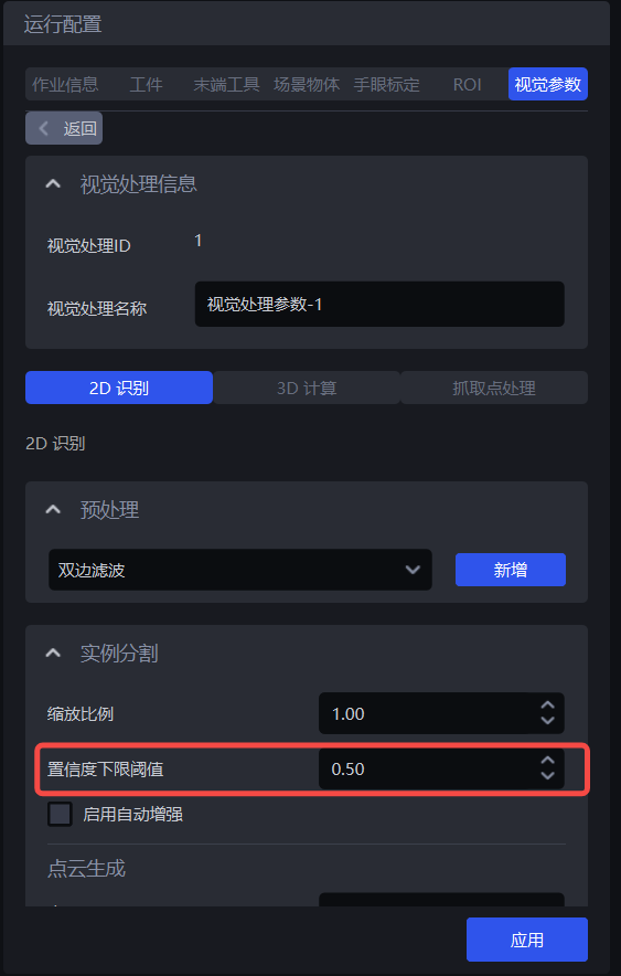
Only the recognition results with a deep learning model recognition result score higher than the Confidence lower limit Threshold are retained.
- Use Scene
This function can be adjusted when the instance selected by the detection result box does not meet expectations.
- Parameter description * *
Default value: 0.5
Value range: [0.01, 1.00]
Adjust parameters
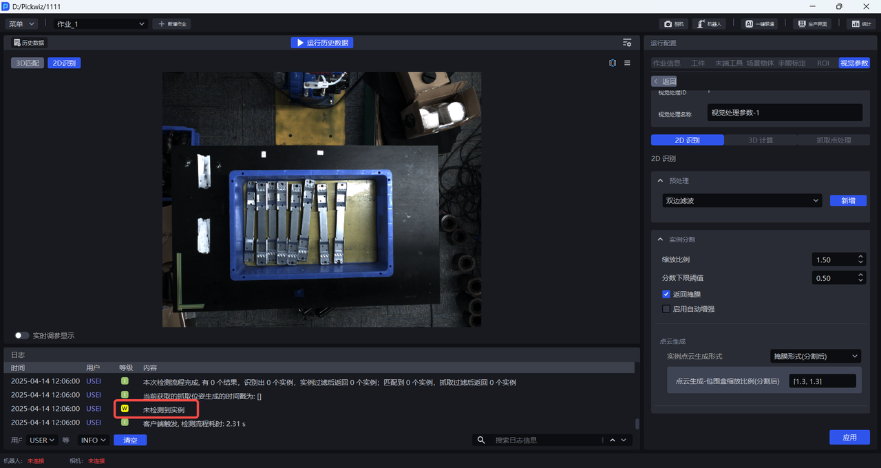
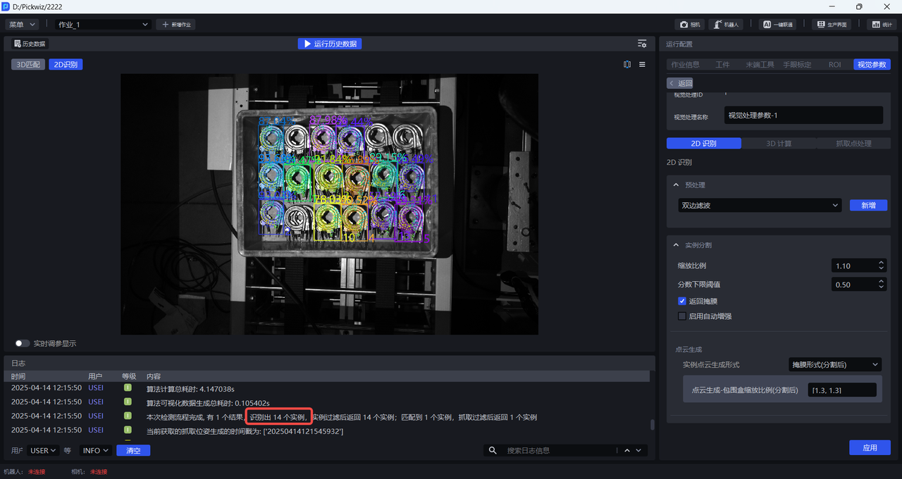
- If the model detects fewer instances, the Threshold should be reduced; if the value is too small, it may affect the accuracy of image recognition.
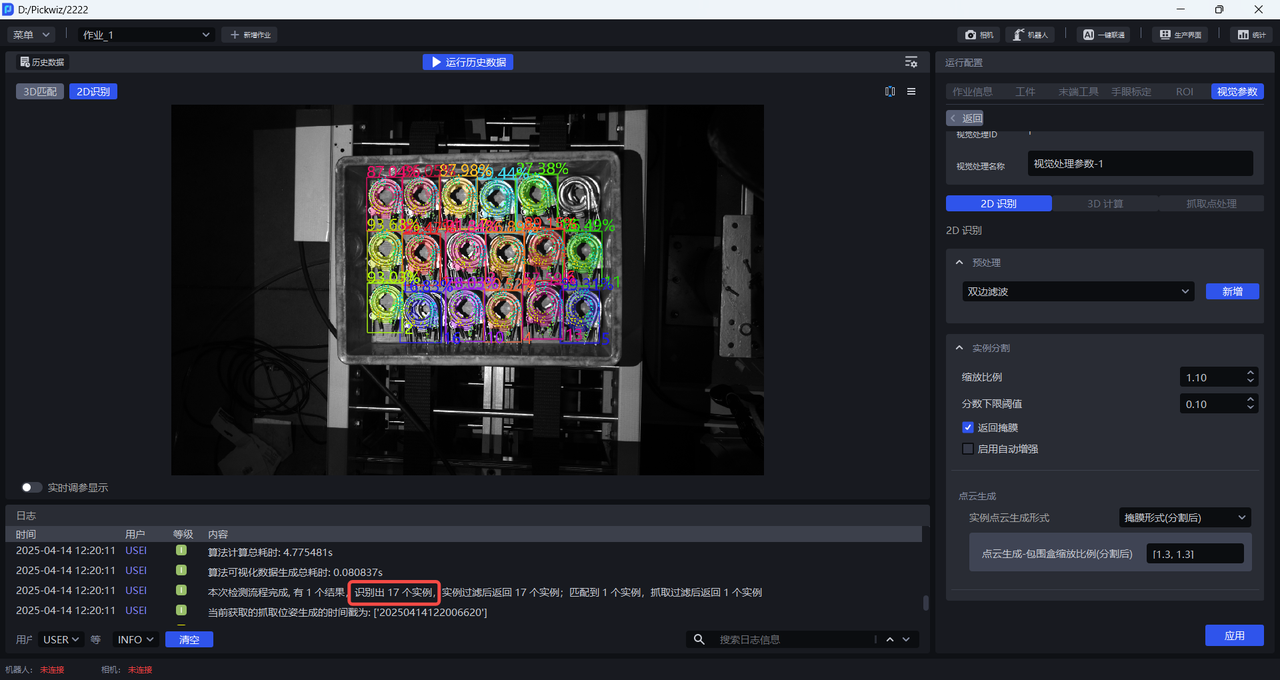
- If erroneous instances are detected because the Confidence lower limit Threshold is too small, and these erroneous instances need to be removed, the Threshold should be increased; if the value is too large, the retained detection results may be zero and no results will be output.
1.2.3 Enable Auto Enhance
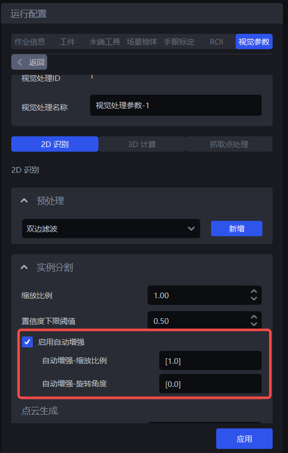
- Function
Inference is achieved by combining all the values in the input scaling ratio and rotation angle, and returning all results that are greater than the set Confidence lower limit Threshold after the combination, which can improve the model inference accuracy. But it adds time.
- Use Scene
A single scaling ratio cannot meet the actual scene requirements, resulting in incomplete detection or high inclination of object placement.
- Example
If the auto-enhancement-scaling ratio is set to [0.8, 0.9, 1.0] and the auto-enhancement-rotation angle is set to [0, 90.0] , then combine the values in the scaling ratio and rotation angle, and the model will automatically generate 6 types of images for Inference. Finally, these 6 types of Inference results will be unified together, and a result greater than the Confidence lower limit Threshold will be output.
Auto Enhance-Zoom

- Function
Scale the original image multiple times and perform multiple inferences, and output the comprehensive inference results.
- Use Scene
A single scaling ratio cannot meet the actual scene requirements, resulting in incomplete detection.
- Parameter description * *
Default value: [1.0]
Value range: The range of each scaling ratio is [0.1, 3.0]
Multiple scaling ratios can be set, and each scaling ratio is separated by a comma.
- Adjust parameters
Fill in multiple 1.2.1 scaling Obtained scaling ratio with better detection effect
Auto Enhancement-Rotation Angle

- Function
Rotate the original image multiple times and perform multiple inferences, and output the comprehensive inference results.
- Use Scene
Used when objects are placed far away from the coordinate axis
- Parameter description * *
Default value: [0.0]
Value range: The value range of each rotation angle is [0, 360]
Multiple rotation angles can be set, and each rotation angle is separated by a comma.
- Adjust parameters
Adjust the automatic enhancement-rotation angle according to the angle of the object in the actual scene. The tilt angle can be determined based on the pattern and mouth shape of the sack, the edges of the carton and the brand logo.
1.3 Point Cloud generation
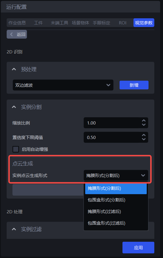
| instance Point Cloud generated form | mask form (after segmentation) | — | uses the split instance mask to generate Point Cloud |
| bounding box form (after segmentation) | bounding box scaling (after segmentation) | uses the split instance bounding box to generate Point Cloud | |
| Whether color is needed to generate Point Cloud (after segmentation) | Does the instance Point Cloud generated by need to be attached with the color | ||
| mask form (after filtering) | — | uses the filtered instance mask to generate Point Cloud | |
| bounding box form (after filtering) | bounding box scaling (after filtering) | uses the filtered instance bounding box to generate Point Cloud | |
| Whether color is required to generate Point Cloud (after filtering) | Does the instance Point Cloud generated by need to be attached with the color |
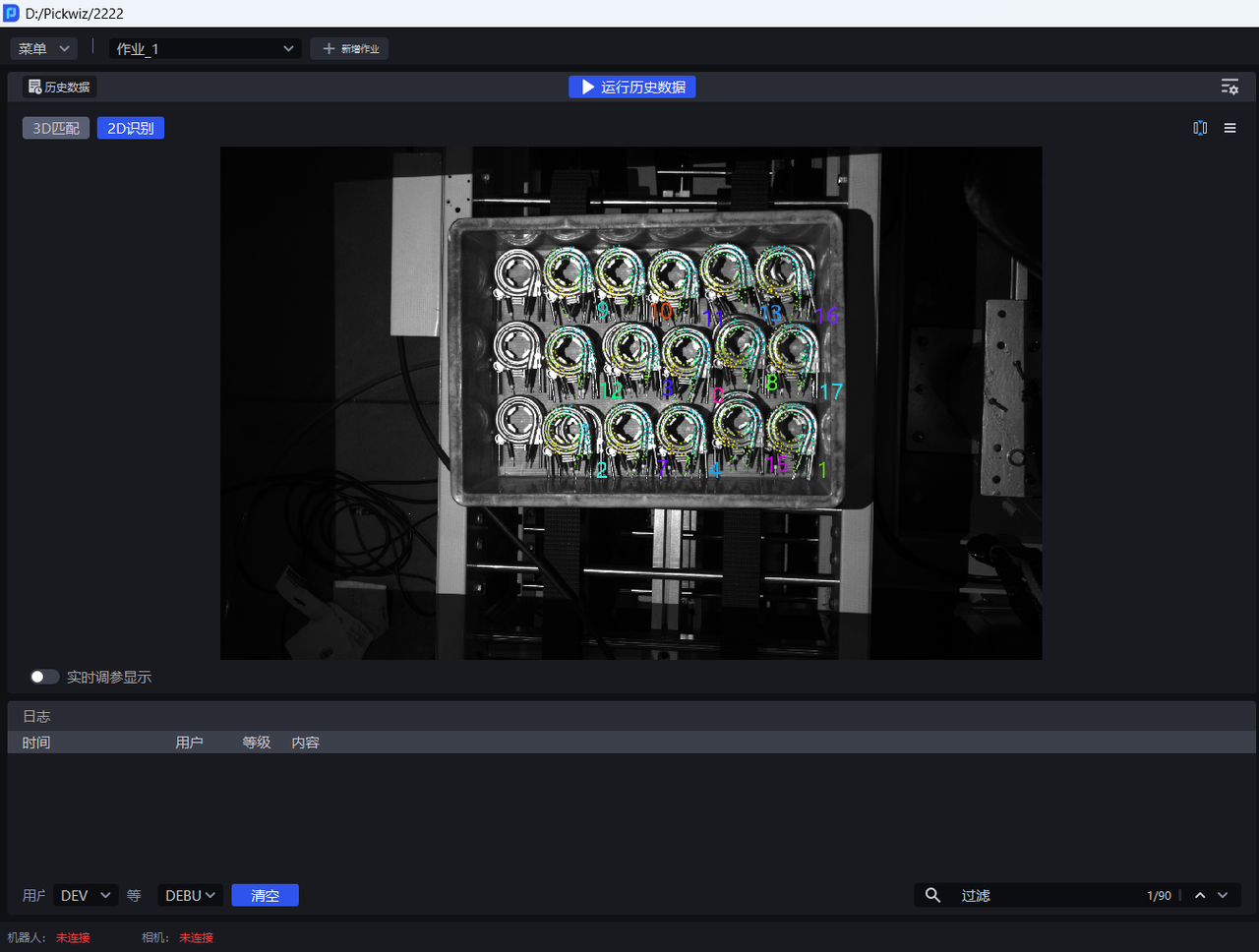
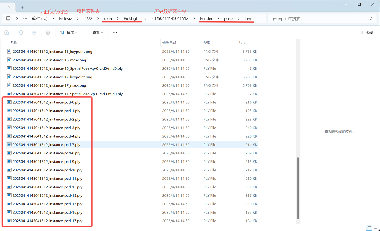
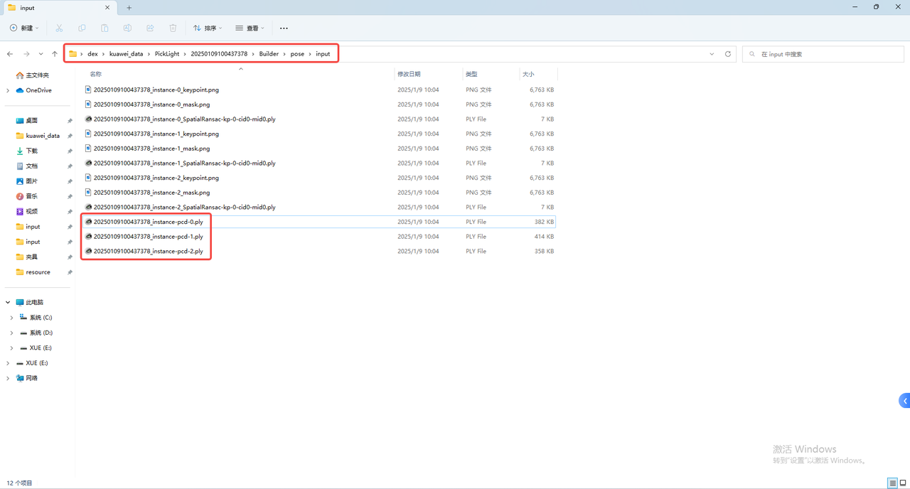
If acceleration is not required, there is no need to use the instance filtering function. Use mask form (after segmentation) or bounding box form (after segmentation) to generate an instance Point Cloud, which can be found in Project storage folder \Project name\data\PickLight\Historical data timestamp\Builder\pose\input folder View the generated instance Point Cloud;
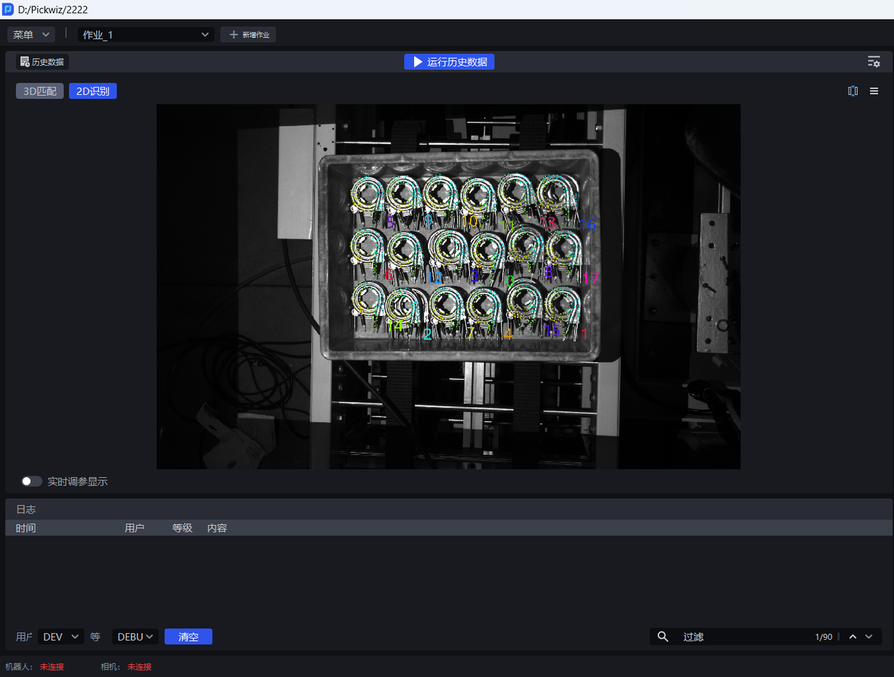
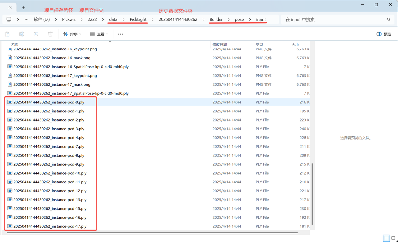
If acceleration is required, you can use the instance filtering function to filter instances, and use mask form (after filtering) or bounding box form (after filtering) to generate instance Point Cloud, which can be found in Project storage folder\Project name\data\PickLight\Historical data timestamp\Builder\pose\input folder View the generated instance Point Cloud
1.4 instance filtering
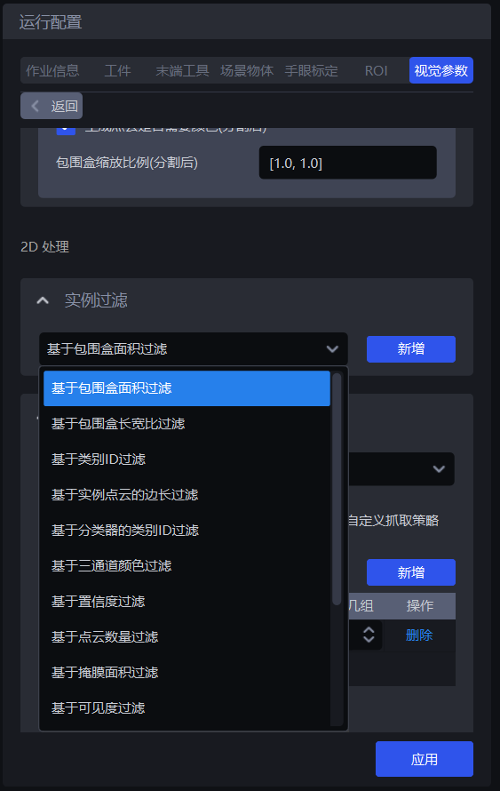
1.4.1 filtering based on bounding box area
- Function introduction
Filter based on the pixel area of the bounding box of the detected instance.
- Use Scene
It is suitable for scenes with large differences in instance bounding box area. By setting the upper limit and lower limit of the bounding box area, the noise in the image is filtered to improve the accuracy of image recognition and avoid noise adding time to subsequent processing.
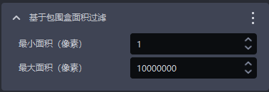
- Parameter description * *
| Parameter | Description | Default value | Parameter range | unit |
|---|---|---|---|---|
| Minimum area (pixels) | This Parameter is used to set the minimum filter area of the bounding box. Instances with a bounding box area lower than this value will be filtered | 1 | [1, 10000000] | pixels |
| Maximum area (pixels) | This Parameter is used to set the maximum filtering area of the bounding box. Instances with a bounding box area higher than this value will be filtered | 10000000 | [2, 10000000] | pixels |
- Example
Running by default, you can view the bounding box area of each instance in the log, as shown in the figure below.
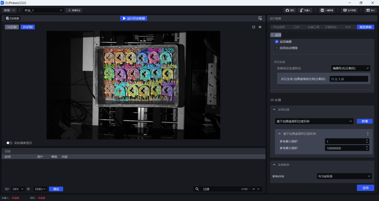
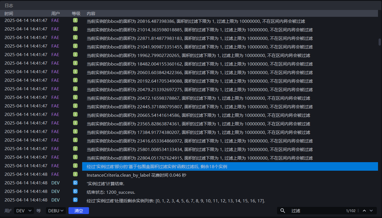
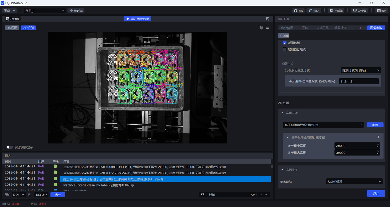
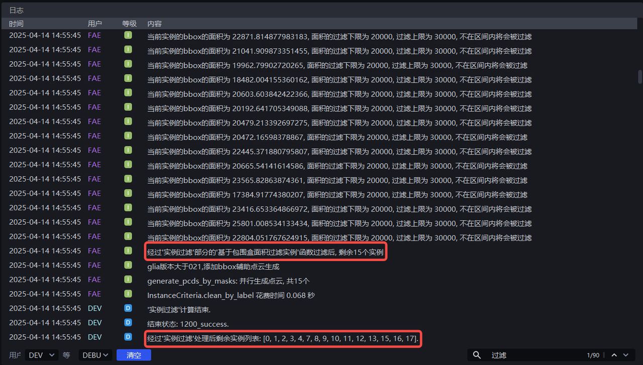
Adjust minimum area based on the bounding box area of each instance and Maximum area, if you set Minimum area to 20000 and Maximum area to 30000, you can filter out instances with a pixel area less than 20000 or greater than 30000. You can view the instance filtering process in the log.
1.4.2 filtering based on bounding box aspect ratio
- Function introduction
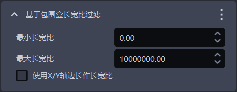
Instances with bounding box aspect ratios outside the specified range will be filtered out
- Use Scene
Suitable for Scenes where the aspect ratio of the bounding box of the instance is greatly different.
- Parameter description * *
| Parameter | Description | Default value | Parameter range |
|---|---|---|---|
| Minimum aspect ratio | The minimum value of the bounding box aspect ratio. Instances with a bounding box aspect ratio lower than this value will be filtered | 0 | [0, 10000000] |
| Maximum aspect ratio | The maximum value of the bounding box aspect ratio. Instances with a bounding box aspect ratio higher than this value will be filtered | 10000000 | [0, 10000000] |
| uses the X/Y axis side length as the aspect ratio | is not checked by default and uses the length ratio of the longer side/shorter side of the bounding box as the aspect ratio, which is suitable for situations where the length difference between the long and short sides of the bounding box is large; When checked, the length ratio of the X-axis/Y-axis sides of the bounding box in the pixel coordinate system is used as the aspect ratio. This is suitable for the situation where the long side/short side ratio of most normal instance bounding boxes is similar, but the ratio of the X-axis length/Y-axis length of some abnormally identified instance bounding boxes is quite different. | Uncheck | / |
1.4.3 Filter instances based on category ID
- Function introduction
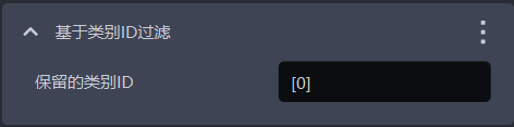
Filter by instance category
- Use Scene
Suitable for scenes with multiple types of targets for incoming materials
- Parameter description * *
| Parameter | Description | Default value |
|---|---|---|
| Reserved category ID | Instances with category IDs in the list are retained, and instances with category IDs not in the list will be filtered | [0] |
- Example
1.4.4 Edge length filtering based on instance Point Cloud
- Function introduction
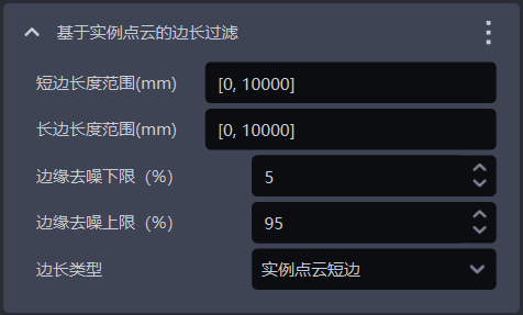
Filter based on the long and short sides of the instance Point Cloud
- Use Scene
It is suitable for scenes where the distance between the instance Point Clouds on the x-axis or the y-axis is quite different. By setting the distance range of the instance Point Cloud, you can filter the noise in the image, improve the accuracy of image recognition, and avoid noise adding time to subsequent processing.
- Parameter description * *
| Parameter | Description | Default value | Parameter range | unit |
|---|---|---|---|---|
| short side length range (mm) | Point The side length range of the short side of the Cloud is | [0, 10000] | [0, 10000] | mm |
| long side length range (mm) | Point Cloud's long side length range | [0, 10000] | [0, 10000] | mm |
| edge denoising lower limit (%) | Extract the lower limit of the percentage of the X/Y value (Camera coordinate system) in the instance Point Cloud, remove the Point Cloud outside the upper and lower limits, and avoid noise affecting the length calculation | 5 | [0, 100] | / |
| edge denoising upper limit (%) | Extract the upper limit of the percentage of the X/Y value (Camera coordinate system) in the instance Point Cloud, remove the Point Cloud outside the upper and lower limits, and avoid noise affecting the length calculation | 95 | [0, 100] | / |
| side length type | Filter by the long and short sides of the instance Point Cloud. Instances whose lengths of the long and short sides are not within the range will be filtered | instance Point Cloud short side | instance Point Cloud short side; instance Point Cloud long side; instance Point Cloud long side and short side | / |
- Example
1.4.5 Classifier based category ID filtering
- Function introduction
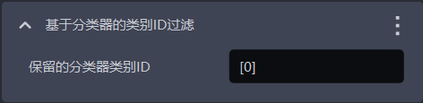
Instances are filtered based on the class ID of the classifier, instances not within the reference class will be filtered.
- Use Scene
In a multi-type TargetScene, the Visual Model may detect multiple types of Targets, but the actual Task may only require one type of Target. In this case, you can use this function to filter out unnecessary Targets.
- Parameter description * *
The default value is [0], that is, instances with category ID 0 are retained by default, category ID Instances not in the list will be filtered.
1.4.6 based on three-channel color filtering
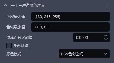
- Function introduction
Instances can be filtered out by three-channel color threshold (HSV or RGB).
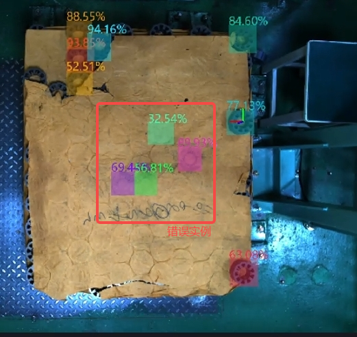
- Use Scene
There is a clear distinction between the colors of incorrect instances and correct instances.
- Parameter description * *
| Parameter | Description | Default value | value range |
|---|---|---|---|
| color gamut maximum value | Maximum color value | [180,255,255] | [[0,0,0],[255,255,255]] |
| color gamut minimum value | minimum color value | [0,0,0] | [[0,0,0],[255,255,255]] |
| filter percentageThreshold | color pass rateThreshold | 0.05 | [0,1] |
| Reverse filtering | If checked, instances with a ratio outside the color range lower than the Threshold will be eliminated. If not checked, instances with a ratio within the color range lower than the Threshold in the instance image will be eliminated. | Uncheck | / |
| color mode | color space selected in color filtering | HSV color space | RGB color spaceHSV color space |
- Example
1.4.7 based on Confidence filtering
- Function introduction
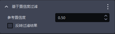
Filter based on the instance’s Confidence score
- Use Scene
Applicable to Scenes with large differences in instance confidence
- Parameter description * *
| Parameter | Description | Default value | Parameter range |
|---|---|---|---|
| ReferenceConfidence | retains instances with Confidence greater than Threshold and filters instances with Confidence less than Threshold. | 0.5 | [0,1] |
| Invert filter result | After inversion, instances with visibility Confidence less than Threshold are retained, and instances with Confidence greater than Threshold are filtered. | Uncheck | / |
- Example
1.4.8 Filter based on the number of Point Clouds
- Function introduction
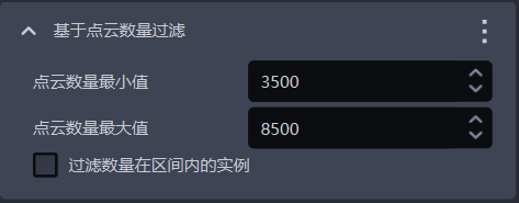
Filter based on the number of instance Point Clouds after downsampling
- Use Scene
Instance Point Cloud has more noise
- Parameter description * *
| Parameter | Description | Default value | Parameter range |
|---|---|---|---|
| Point Cloud quantity minimum | Point Cloud quantity minimum value | 3500 | [1, 10000000] |
| Point Cloud maximum number | Point Cloud maximum number | 8500 | [2, 10000000] |
| filters instances whose number is within the interval | If checked, the instances whose Point Cloud quantity is within the minimum and maximum range will be filtered. If not checked, the instances whose Point Cloud quantity is not within the range will be filtered. | Uncheck | / |
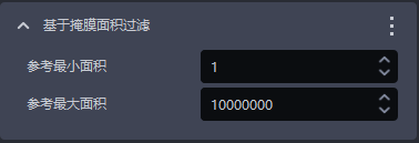
1.4.9 filtering based on mask area
- Function introduction
Filter the image mask based on the mask pixel sum (i.e. pixel area) of the detected instance.
- Use Scene
It is suitable for Scenes with large differences in instance mask area. By setting the upper and lower limits of the mask area, the noise in the image mask is filtered to improve the accuracy of image recognition and avoid noise adding time to subsequent processing.
- Parameter setting instructions
| Parameter name | Description | Default value | Parameter range | unit |
|---|---|---|---|---|
| reference minimum area | This Parameter is used to set the minimum filtering area of the mask. Instances with a mask area lower than this value will be filtered | 1 | [1, 10000000] | pixels |
| Reference maximum area | This Parameter is used to set the maximum filtering area of the mask. Instances with a mask area higher than this value will be filtered | 10000000 | [2, 10000000] | pixels |
- Example
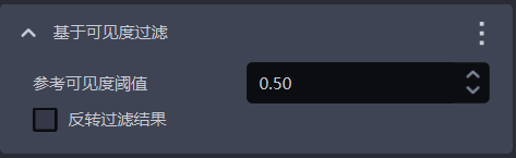
1.4.10 filtering based on visibility
- Function introduction
Filter based on the visibility score of the instance
- Use Scene
Suitable for Scenes where the visibility of instances varies greatly.
- Parameter description * *
| Parameter | Description | Default value | Parameter range |
|---|---|---|---|
| Reference Visibility Threshold | retains instances with visibility greater than Threshold and filters instances with visibility less than Threshold. Visibility is used to determine the degree to which instances in an image are visible. The more the Target is occluded, the lower the visibility. | 0.5 | [0,1] |
| Invert filter result | After inversion, instances with visibility less than Threshold are retained and instances with visibility greater than Threshold are filtered. | Uncheck | / |
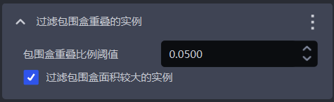
1.4.11 filter bounding box overlap example
- Function introduction
Filter instances where bounding boxes intersect and overlap
- Use Scene
Applies to Scenes where the instance's bounding boxes intersect each other
- Parameter description * *
| Parameter | Description | Default value | Parameter range |
|---|---|---|---|
| bounding box overlap ratio Threshold | The ratio of the intersection area of the bounding box to the area of the instance bounding box Threshold | 0.05 | [0, 1] |
| Example of filtering bounding box with large area | If checked, the instance with the larger area among the instances where the two bounding boxes intersect will be filtered. If not checked, the instance with the smaller area among the instances where the two bounding boxes intersect will be filtered. | Check | / |
- Example
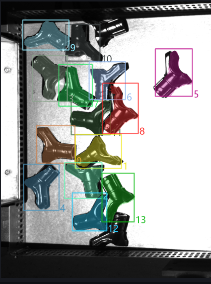
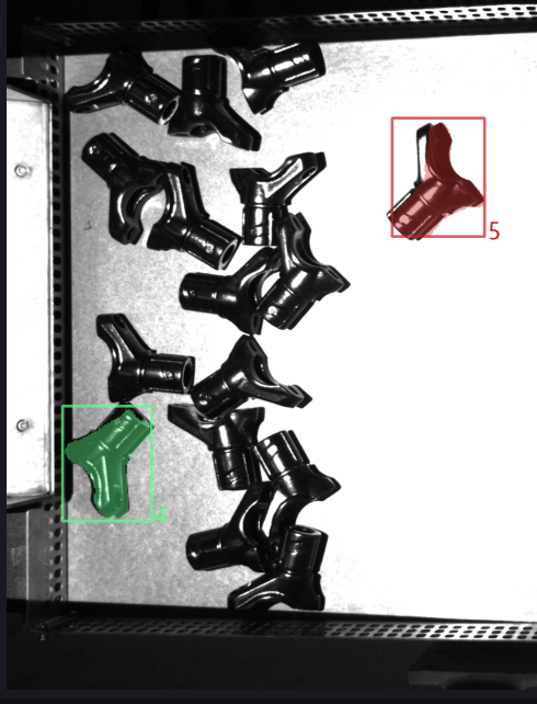
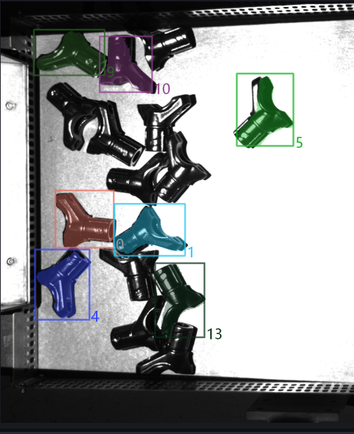
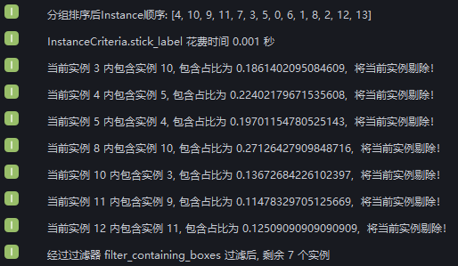
New Filter the surrounded instances and run with the default value. Check the intersection of instance bounding boxes in the log. After instance filtering, there are 2 instances left.
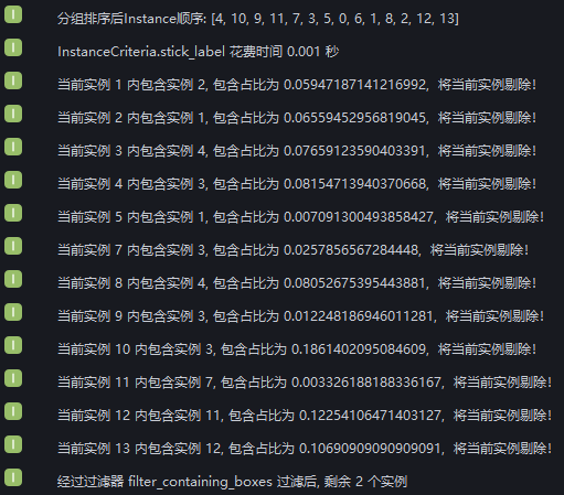
It can be seen from the log that 12 instances were filtered out because of bounding box intersections, and the remaining 2 instances had no intersections.
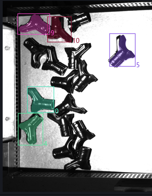
Set Bounding Box Overlap Ratio Threshold to 0.1 and check Whether to filter larger instances, check the instance filtering process in the log. 9 instances were filtered out because the ratio of the intersection area of the bounding box to the area of the instance bounding box was greater than 0.1, 3 instances were retained because the ratio of the intersection area of the bounding box to the area of the instance bounding box was less than 0.1, and 2 instance bounding boxes did not intersect.
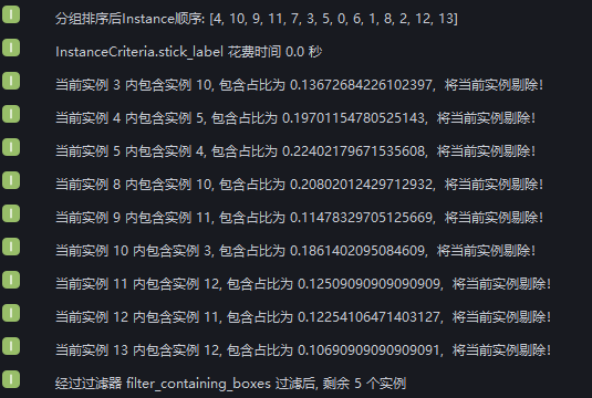
Set the Bounding Box Overlap Ratio Threshold to 0.1 and uncheck it Whether to filter larger instances, check the instance filtering process in the log. The ratio of the intersection area of the bounding box to the area of the instance bounding box of 9 instances is greater than 0.1, but 2 instances are retained because the area of the bounding box is smaller than the instance with which it intersects, so 7 instances are filtered, and 3 instances are retained because the ratio of the intersection area of the bounding box to the area of the instance bounding box is less than 0.1. The bounding boxes of 2 instances do not intersect.
1.4.12 [Master] An example of filtering mask bumps based on the mask/mask external polygon area ratio
- Function introduction
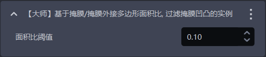
Calculate the area ratio of the mask/mask circumscribed polygon. If it is less than the set Threshold, the instance will be filtered out.
- Use Scene
Suitable for situations where the Target mask has jagged/bumpy edges.
- Parameter description * *
| Parameter | Description | Default value | value range |
|---|---|---|---|
| area ratio Threshold | mask/convex hull area ratio Threshold. If it is less than the set Threshold, the instance will be filtered out. | 0.1 | [0,1] |
1.4.13 [Master] Filtering based on Point Cloud average distance
- Function introduction
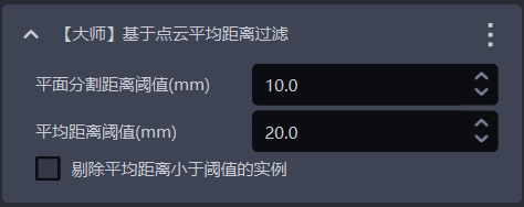
Filter based on the average distance from the midpoint of the Point Cloud to the fitting plane to eliminate uneven instance Point Clouds.
- Use Scene
Suitable for flat TargetPoint Cloud curved Scene
- Parameter description * *
| Parameter | Description | Default value | Parameter range | unit |
|---|---|---|---|---|
| plane division distance Threshold (mm) | Extracts a plane from the curved instance Point Cloud. Points whose distance from the plane is less than the Threshold are regarded as points of the plane | 10 | [-1000, 1000] | mm |
| Average distance Threshold (mm) | The average distance from the points in the Point Cloud of the instance to the extraction plane | 20 | [-1000, 1000] | mm |
| Eliminate instances with an average distance less than Threshold | If checked, the average distance from the filter point to the extraction plane is less than the average distance Threshold. If not checked, the average distance from the filter point to the extraction plane is greater than the average distance Threshold. | Uncheck | / | / |
1.4.14 [Master] Filter occluded instances based on the mask/bounding box area ratio
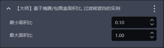
- Function introduction
Calculate the mask/bounding box area ratio. Instances whose ratio is not within the maximum and minimum range will be filtered.
- Use Scene
Used to filter instances of occluded Targets
- Parameter description * *
, conversely, the representation may be occluded.
| Parameter | Description | Default value | value range |
|---|---|---|---|
| minimum area ratio | The lower limit of the mask/bounding box area ratio range. The smaller the ratio, the higher the degree of occlusion of the instance. | 0.1 | [0,1] |
| maximum area ratio | The upper limit of the mask/bounding box area ratio range. The closer the ratio is to 1, the less occluded the instance is. | 1.0 | [0,1] |
1.4.15 [Master] Determine whether the top instance is fully detected
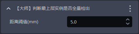
- Function introduction
One of the anti-fool mechanisms, it determines whether all the top-level instances have been checked out. If there are top-level instances that have not been checked out, an error will be reported and the workflow will end.
- Use Scene
It is suitable for capturing scenes once and capturing multiple times or scenes that must be captured in order to prevent missing captures from incomplete instance detection and affecting subsequent tasks.
- Parameter description * *
| Parameter | Description | Default value | Parameter range | unit | Parameter adjustment |
|---|---|---|---|---|---|
| distance Threshold | is used to determine the top-level Target. If the distance between a point and the highest point of the TargetPoint Cloud is less than the distance Threshold, then the point is considered to be the top-level Point Cloud. Otherwise, the point is considered not to be the top-level Point Cloud. | 5 | [0.1, 1000] | mm | should be less than the height of Target |
1.5 instance sorting
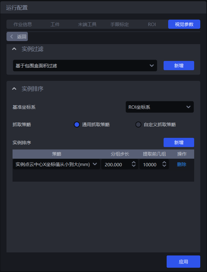
- Function introduction
Group, sort, and extract instances according to the selected strategy
- Use Scene
Universal scene for depalletizing, disordered grabbing, and orderly loading and unloading
**If sorting is not required, no specific strategy can be configured. **
1.5.1 datum coordinate system
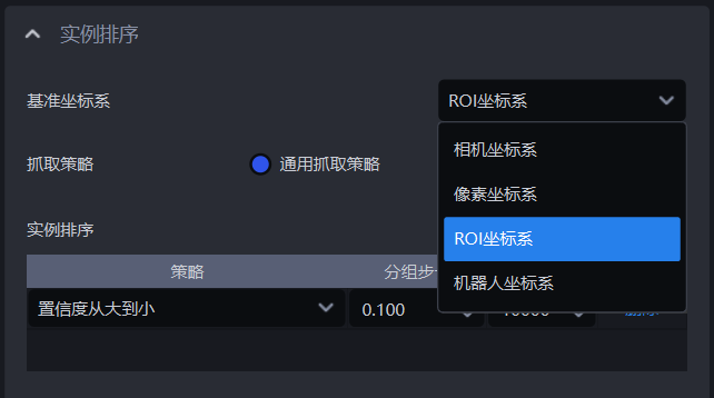
- Function introduction
Set a unified coordinate system for all instances and group and sort the instances
- Use Scene
Common to destacking Scene, disordered grabbing Scene, and orderly loading and unloading Scene
When using coordinate-related strategies, you should first set the base coordinate system
- Parameter description * *
| Parameter | Description | Illustration |
|---|---|---|
| Camera coordinate system | The origin of the coordinate system is above the object, and the positive Z-axis direction is downward; the XYZ value is the value of the center point of the object in this coordinate system | 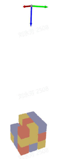 |
| ROI coordinate system | The origin of the coordinate system is roughly at the center of the stack, with the positive direction of the Z axis pointing upward; the XYZ value is the value of the center point of the object in this coordinate system | 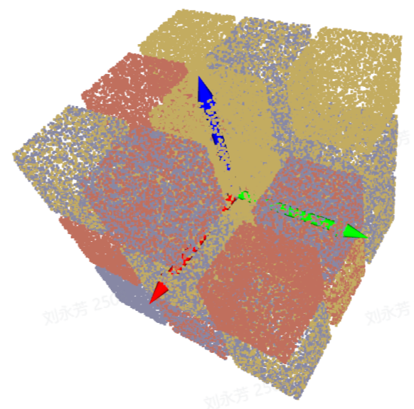 |
| Robot arm coordinate system | The origin of the coordinate system is on the robot arm itself, and the positive direction of the Z axis is generally upward; the XYZ value is the value of the center point of the object in this coordinate system |  |
| pixel coordinate system | The origin of the coordinate system is at the left vertex of the RGB image, which is a two-dimensional plane coordinate system; the values of | 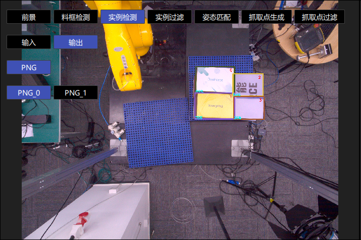 |
1.5.2 general crawling strategy
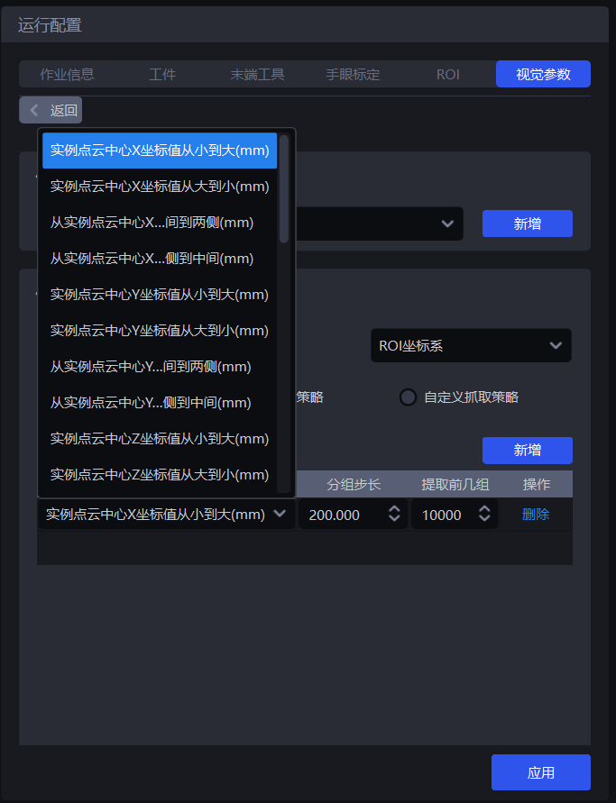
- Parameter description * *
| Parameter | Description | Default value |
|---|---|---|
| Strategy | Select the value used for group sorting and the sort order. Multiple criteria can be stacked, including instance Point Cloud center XYZ coordinate values, bounding box aspect ratio, and distance from the instance Point Cloud center to ROI center. They are executed sequentially. | instance Point Cloud center X coordinate value from small to large (mm) |
| grouping step size | Divide the instances into several groups according to the selected strategy and step size. The grouping step size is the interval between the two groups of instances. If the strategy selects "Instance Point Cloud center Z coordinate value from large to small (mm)", then the Z coordinates of all instance Point Cloud centers are sorted from large to small, and then the Z coordinates are grouped according to the step size. The corresponding instances are also divided into several groups. | / |
| extracts the first few groups | After is grouped and sorted, how many groups of instances need to be retained? | 10000 |
| policy name* | Description | grouping step size | extracts the first few groups | |
|---|---|---|---|---|
| Default value | value range | Default value | ||
| instance Point Cloud center XYZ coordinate value from large to small/small to large (mm) | Use the XYZ coordinate value of the Point Cloud center of each instance for group sorting Before using this strategy for sorting, you should first set the base coordinate system | 200.000 | (0, 10000000] | 10000 |
| From the middle to both sides of the XY coordinate axis of the instance Point Cloud center/From both sides of the XY coordinate axis of the instance Point Cloud center to the middle (mm) | Use the XY coordinate value of the Point Cloud center of each instance to group and sort according to the direction of "middle to both sides" or "both sides to the middle" Before using this strategy for sorting, you should first set the reference coordinate system | 200.000 | (0, 10000000] | 10000 |
| Bounding box center XY coordinate value from large to small/small to large (mm) | uses the XY coordinate value of the center point of the bounding box of each instance in the pixel coordinate system to group and sort | 200.000 | (0, 10000000] | 10000 |
| Bounding box aspect ratio from large to small/small to large | Use the ratio of the long edge/wide edge of the bounding box for group sorting | 1 | (0, 10000] | 10000 |
| From the center of the bounding box center XY coordinate axis to both sides/both sides to the middle (mm) | uses the XY coordinate value of the center point of the bounding box to group and sort in the direction of "middle to both sides" or "both sides to the middle" | 200.000 | (0, 10000000] | 10000 |
| Target type ID from large to small/small to large | uses Target type ID for group sorting, suitable for multi-type TargetScene | 1 | [1, 10000] | 10000 |
| Local feature ID from large to small/small to large | Use the ID of local features for group sorting | 1 | [1, 10000] | 10000 |
| ConfidenceFrom large to small/small to large | Group sorting using Confidence of each instance | 1 | (0, 1] | 10000 |
| Visibility from small to large/large to small | Group sorting using visibility of each instance | 1 | (0, 0.1] | 10000 |
| Mask area from large to small/small to large | Group sorting using mask area of each instance | 10000 | [1, 10000000] | 10000 |
| instance Point Cloud center distance from ROI center near to far/far to near (mm) | uses the distance between the Point Cloud center of each instance and the center of the ROI coordinate system for group sorting | 200.000 | (0, 10000000] | 10000 |
| instance Point Cloud center distance from robot coordinate origin point from near to far/far to near (mm) | Use the distance between the Point Cloud center of each instance and the origin of the Robot coordinate system for group sorting | 200.000 | (0, 10000000] | 10000 |
- Example
1.5.3 Custom crawling strategy

(1) Function description
Switch the crawl strategy to custom crawl strategy and click New A custom crawling strategy can be added.
Customize the order in which each Target is crawled. If it is difficult to achieve crawling using a general crawling strategy or it is difficult to adjust the appropriate Parameter due to issues such as Point Cloud noise, you can consider using a custom crawling strategy.
The custom fetching strategy is applicable to the depalletizing Scene and the ordered loading and unloading Scene. It is not applicable to the unordered fetching Scene because the Targets of the custom fetching strategy must be in order (that is, the order of the Targets is fixed).
Custom crawling strategies can only be used in combination with a single general crawling strategy, and the strategy can only select Z coordinates from small to large.
(2)Parameter description
| Parameter | Description | Default value | value range | Parameter adjustment |
|---|---|---|---|---|
| IOUThreshold | represents the overlap degree Threshold between the marked bbox box and the detected bbox box. The overlap degree is used to determine which sorting method on the picture should be selected when the current Target instance is sorted. | 0.7 | [0,1] | Threshold The larger the match, the stricter the matching, and the worse the anti-interference performance will be. Small changes in shape or position may cause matching failure, and the wrong custom strategy may be matched and sorted in the wrong order. |
| Pixel Distance Threshold | represents the difference in size between the matched bbox box and the detected bbox box. | 100 | [0,1000] | The smaller the Threshold, the stricter the matching and the better the anti-interference performance. If the Target placement between different layers is similar, the custom strategy may be mismatched, resulting in an incorrect sorting order. |
(3)Select the datum coordinate system
When using a custom crawling strategy, only Camera coordinate system or pixel coordinate system can be selected.
If there are multiple layers of Target, select the Camera coordinate system; if there is only one layer of Target, select the Pixel coordinate system.
(4) Strategy, grouping step size, extracting the first few groups
| Parameter | Description | Default value |
|---|---|---|
| Strategy | can only select instance Point Cloud center Z coordinate value from large to small/small to large (mm) | / |
| grouping step size | Sort the Z coordinates of the instances from small to large according to the Z coordinate strategy from small to large, and divide the instances into several groups according to the step size | 10000 |
| extracts the first few groups | After is grouped and sorted, how many groups of instances need to be retained? | 10000 |
(5) Take pictures/add local images
Click Take a picture to get an image from the currently connected Camera, or click Add local image to import an image from the local. How many layers or how many different placements of Target there are, depends on how many pictures you need to take a picture or add a local image. If each layer is the same, you only need one. Right-click the image to delete it.
Long press and drag the left mouse button on the acquired image to mark the bbox box. The DELETE key can gradually delete the marked bbox box.
2. 3D calculations
This section mainly explains the related functions that affect Pick Point generation and provides parameter adjustment suggestions.
2.1 Pretreatment
The preprocessing of 3D calculation is to process the 3DPoint Cloud before performing pose estimation on the instance and generating Pick Point.
2.1.1 Point Cloud Clustering Denoising
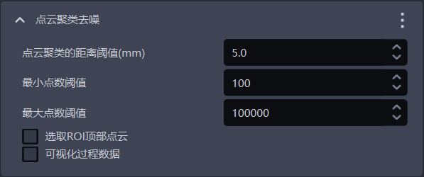
- Function
Remove noise through Point Cloud clustering method
- Use Scene
There is a lot of noise in the instance Point Cloud.
Point Cloud clustering denoising may filter part of the TargetPoint Cloud due to the adhesion between the TargetPoint Cloud and the noise Point Cloud.
- Parameter description * *
| Parameter name | Description | Default value | value range | unit | Parameter adjustment recommendation |
|---|---|---|---|---|---|
| Point Cloud clustering distance Threshold (mm) | determines whether the Point Clouds in the space are of the same category. If the distance between Point Clouds is lower than the Threshold, they are of the same category. | 5 | [0.1, 1000] | mm | Generally, there is no need to change the point spacing that is greater than the TargetPoint Cloud and less than the minimum distance between the TargetPoint Cloud and the noise Point Cloud |
| Minimum point Threshold | Point Cloud clusters smaller than this number of points will be filtered | 100 | [1,10000000] | / | generally does not need to be changed. According to the noise level in the instance Point Cloud, increase the minimum number of points Threshold |
| Maximum pointsThreshold | Point Cloud clusters larger than this number will be filtered | 100000 | [1,10000000] | / | Generally does not need to be changed. If the number of TargetPoint Cloud is greater than 100000, increase the maximum point Threshold |
| Select the top point of ROI Cloud | If is checked, the Z coordinate average of the same category Point Cloud in the ROI coordinate system is calculated and sorted, and the Point Cloud category with the largest Z coordinate average (top Point Cloud) is retained. If not checked, all Point Clouds that meet the conditions are retained | Uncheck | / | / | If the TargetPoint Cloud is above the noise Point Cloud, check to retain the TargetPoint Cloud; if the TargetPoint Cloud is below the noise Point Cloud, you should adjust the Z axis of the ROI coordinate system downward to retain the TargetPoint Cloud |
| Visualizing process data | If checked, the denoised Point Cloud will be saved, which can be found in C:_data | Uncheck | / | / | In debugging mode, if you need to save visual data, you can check |
- Example
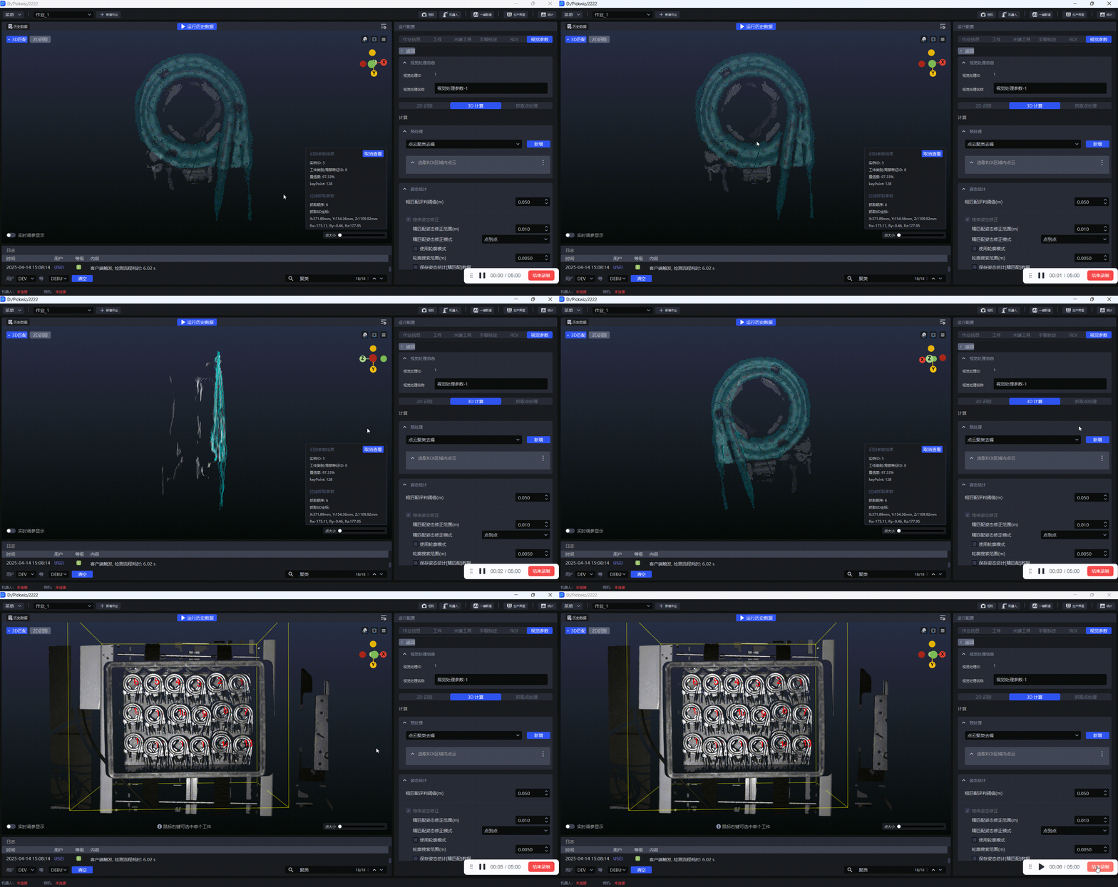
(1) Without using Point Cloud clustering for denoising, the generated instance Point Cloud is as shown in the figure below. Instances 0, 1, and 2 all have more background noise.
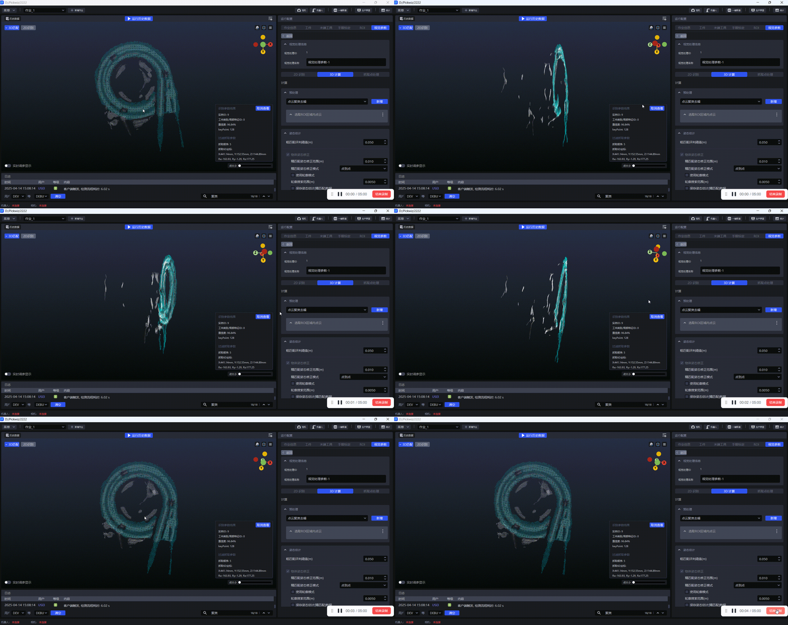
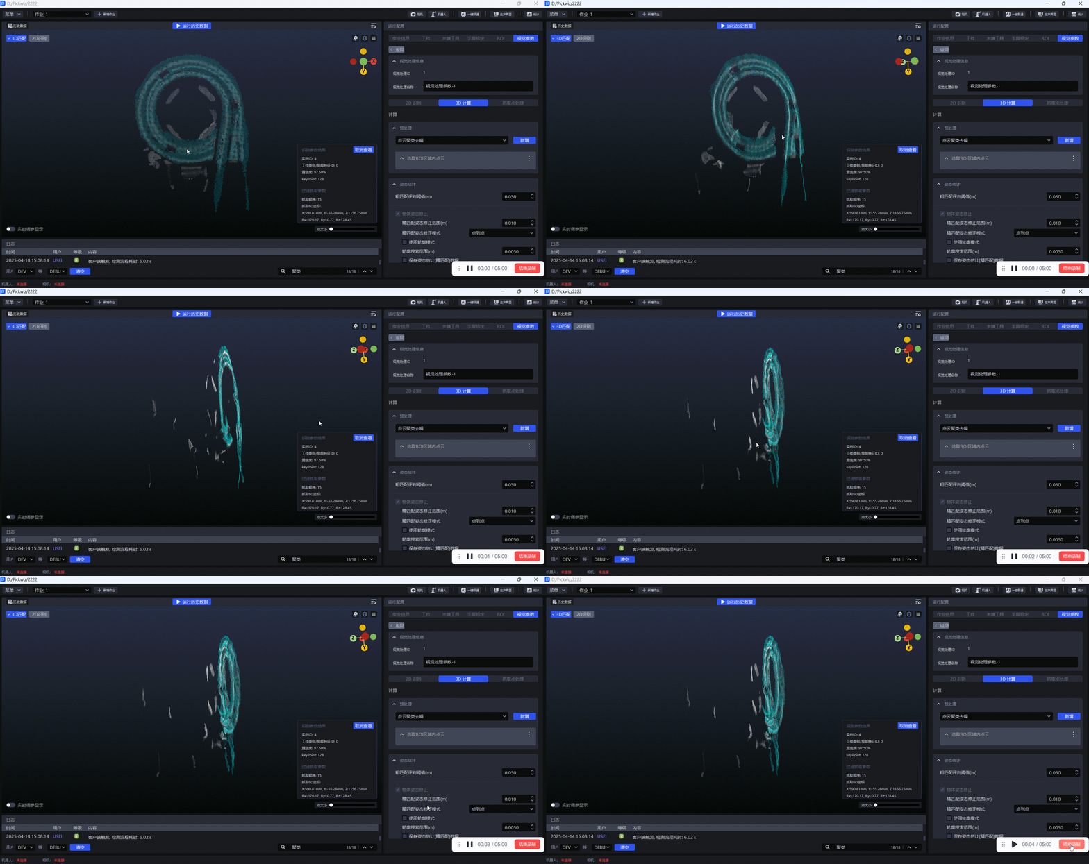
(2) Check Point Cloud Clustering Denoise and run with the default value. If the clustering is successful, the categories with the number of Point Clouds greater than 100 and less than 100,000 in the instance Point Cloud will be retained, and the categories with the number of Point Clouds less than 100 or greater than 100,000 will be filtered. Looking at the logs, we can see that after clustering instances 4, 5, and 9, the number of Point Clouds is greater than 100 and less than 100,000, and Point Clouds are not filtered.
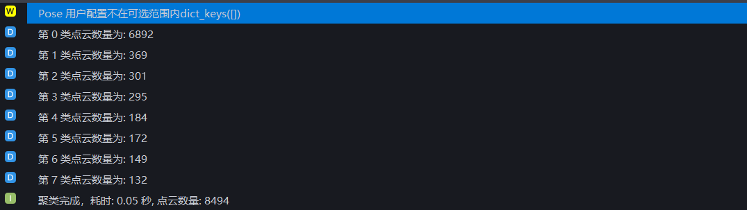
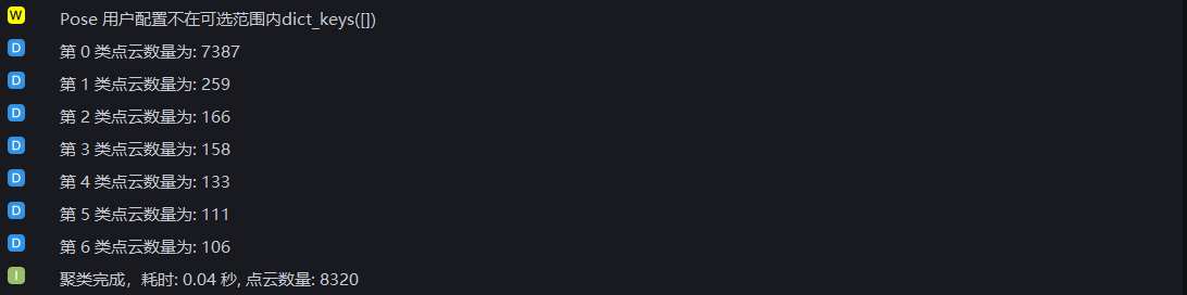
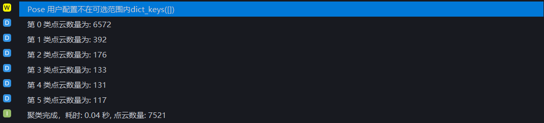
(3) Increase the Minimum Point Threshold to 400, and only retain the 0th type Point Cloud for noise removal in instances 4, 5, and 9.



(4) Check Select the Point Cloud at the top of the ROI, and only retain the Point Cloud category with the largest Z coordinate average in the ROI coordinate system.
As shown in the figure below, instance 7 has 5 types of Point Clouds after clustering. If the minimum point Threshold is set to 400, the 3rd and 4th types of Point Clouds in instance 7 are filtered, and the 0, 1, and 2 types of Point Clouds are retained.


Check Select the top Point Cloud of ROI, and only retain the 0th type Point Cloud for instance 7.
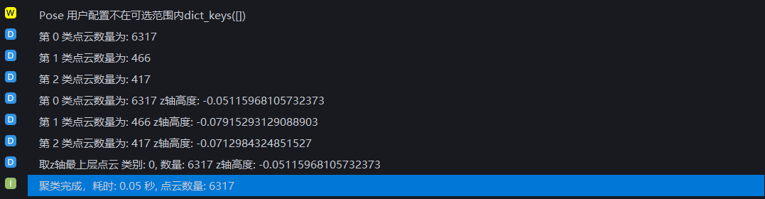
If the noise is at the top and the TargetPoint Cloud is at the bottom, the Z axis of the ROI should be adjusted downward in the visualization window to maximize the average Z coordinate of the TargetPoint Cloud and retain the TargetPoint Cloud. Otherwise, the retained top Point Cloud is noise.
(5) If clustering fails and the log error is as shown below, the Point Cloud clustering distance Threshold should be increased. The Point Cloud clustering distance Threshold should be greater than the point spacing of TargetPoint Cloud and less than the minimum distance between TargetPoint Cloud and noise Point Cloud.

Use meshlab to measure the point spacing of the TargetPoint Cloud in the generated instance Point Cloud and the minimum distance between the TargetPoint Cloud and the noise Point Cloud, as shown in the following figure
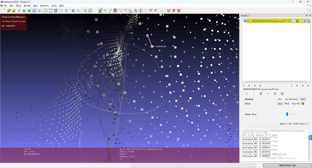
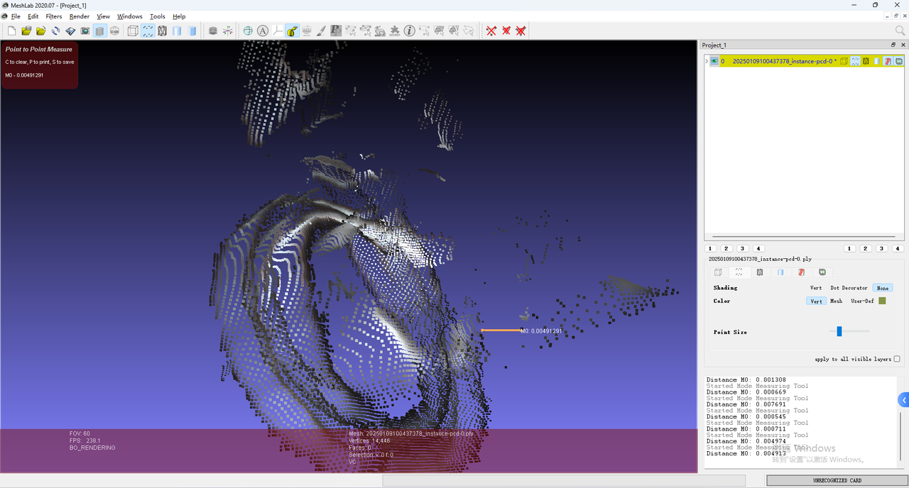
If the number of TargetPoint Clouds is greater than the Maximum Points Threshold, then it may be that the number of Point Clouds is greater than 100,000 and all are filtered, resulting in clustering failure. The Maximum Points Threshold should be increased.
2.1.2 Point Clouddownsampling

- Function
Sampling Point Cloud according to the specified point spacing to reduce the number of calculation points and improve model inference speed, but the accuracy may decrease
- Use Scene
There are too many actual ScenePoint Clouds, so check Point Clouddownsampling.
- Parameter description * *
| Parameter | Description | Default value | Parameter range | unit |
|---|---|---|---|---|
| Point spacing of downsampling (mm) | samples Point Cloud according to the specified point spacing | 5.0 | [0.1, 1000] | mm |
Adjust parameters
The larger the value of downsampling point spacing is, the smaller the number of Point Clouds after downsampling will be, and the Pick Point calculation speed will be accelerated, but the accuracy may be reduced.
The smaller the value of downsampling point spacing is, the greater the number of Point Clouds after downsampling will be, and the Pick Point calculation speed will be reduced and the accuracy will be improved.
2.1.3 Calculation normal vector
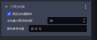
- Function
Calculate the Point Cloud normal vector for subsequent Point Cloud processing.
- Parameter description * *
| Parameter name | Description | Default value | value range |
|---|---|---|---|
| fixed normal vector oriented towards | Whether to fix the orientation when calculating the Point Cloud normal vector. When enabled, the normal vector is determined by the orientation reference vector | Check | / |
| normal vector calculates the number of neighborhood points | The larger the value, the more neighborhood points are referenced, but it may cause local changes to be ignored. The smaller the value, the opposite is true | 30 | [1,200] |
| orientation reference vector | normal vector calculation direction reference vector | [0,0,1] | / |
- Adjust parameters
cannot be changed
2.1.4 Point Cloud contour extraction
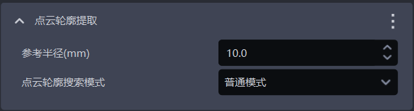
- Function
Extract Target outline from instance Point Cloud
- Use Scene
Use **2.2.2 Object Pose Correction ** in **Use Contour Mode ** should be checked at the same time Point Cloud Contour Extraction
- Parameter description * *
| Parameter name | Description | Default value | value range | unit | Parameter adjustment recommendation |
|---|---|---|---|---|---|
| reference radius (mm) | Search radius for extracting contours in instance Point Cloud | 10 | [0.1,10000000000] | mm | reference radius is recommended to be set to 2.1.2 1/2 of the downsampling point spacing in Point Clouddownsampling, and must be greater than the Point Cloud spacing |
| Point Cloud Contour Search Mode | Search for the pattern of Point Cloud outline | Normal mode | Normal mode; Plane mode | / | Normal mode is generally selected for , and flat mode is selected for flat Target |
- Example
2.1.5 Filter Point Cloud based on color gamut hsv (hue, saturation, brightness)
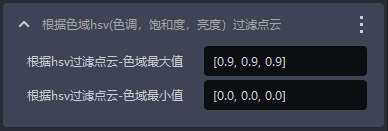
- Function
Filter the Point Cloud according to the hue, saturation, and brightness in the Point Cloud map to select the Point Cloud area that matches the target range.
- Parameter description * *
| Parameter name | Description | Default value | value range |
|---|---|---|---|
| Filter Depth by hsv - Gamut Max | Filters the maximum color value of Point Cloud | [0.9,0.9,0.9] | [[0,0,0],[1,1,1]] |
| filter depth according to hsv - color gamut minimum | Filters the minimum color value of Point Cloud | [0.0,0.0,0.0] | [[0,0,0],[1,1,1]] |
- Example
2.1.6 Filter Point Cloud based on tee color
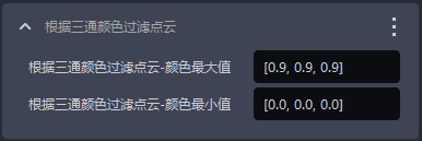
- Function
Filter the Point Cloud based on the tee color to select the Point Cloud area that matches the target range.
- Parameter description * *
| Parameter name | Description | Default value | value range |
|---|---|---|---|
| Filter Point Cloud based on tee color - color maximum | Filters the maximum color value of Point Cloud | [0.9,0.9,0.9] | [[0,0,0],[1,1,1]] |
| Filter depth based on tee color - color minimum | Filters the minimum color value of Point Cloud | [0.0,0.0,0.0] | [[0,0,0],[1,1,1]] |
- Example
2.1.7 Select Point Cloud in ROI area

- Function
Select the Point Cloud in the ROI 3D area from the instance Point Cloud. The default function cannot be deleted.
- Example
2.1.8 Remove points whose normal is greater than the angle Threshold
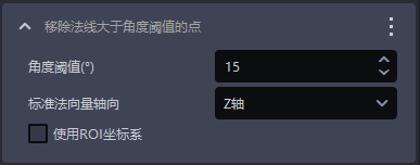
- Function
Remove the Point Cloud where the angle between the normal vector and the standard normal vector axis is greater than the normal vector angle Threshold.
- Use Scene
Surface Target loading and unloading (materials are isolated from each other)
- Parameter description * *
| Parameter name | Description | Default value | value range | unit |
|---|---|---|---|---|
| AngleThreshold | Point Cloud that is greater than the angle Threshold of is considered to be a different instance | 15 | [-360, 360] | |
| standard normal vector axis | The angle between the normal vector of the Point Cloud and the axis of the standard normal vector | Z axis | X/Y/Z axis | / |
| Whether to use the ROI coordinate system | If checked, the angle between the normal vector and the axis of the ROI coordinate system is calculated. If not checked, the angle between the normal vector and the axis of the Camera coordinate system is calculated. | Uncheck | / | / |
2.1.9 Point Cloud Plane Split
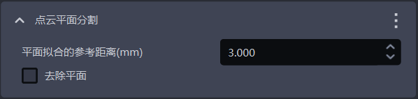
- Function
Retain or remove the plane with the largest number of Point Clouds in the instance Point Cloud
- Use Scene
There is a noise plane in the instance Point Cloud
- Parameter description * *
| Parameter | Description | Default value | value range | unit | Parameter adjustment recommendation |
|---|---|---|---|---|---|
| Reference distance for plane fitting (mm) | If the distance between point and the plane is lower than the reference distance, it is considered to be a point in the plane, otherwise it is considered to be a point outside the plane | 3 | [0.001,10000] | mm | generally does not change |
| Remove plane | If checked, the plane with the largest number of Point Clouds will be removed. If not checked, the plane with the largest number of Point Clouds will be retained. | Uncheck | / | / | If the plane with the largest number of Point Clouds is Target, keep the plane and leave it unchecked; if the plane with the largest number of Point Clouds is noise, remove the plane and check |
2.1.10 Point Cloud removes outliers
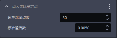
- Function
Identify and remove outlier noise in Point Cloud and improve Point Cloud quality
- Use Scene
The instance Point Cloud contains a lot of outlier noise.
- Parameter description * *
| Parameter name | Description | Default value | value range |
|---|---|---|---|
| reference neighborhood points | Point Cloud The number of points adjacent to each point, that is, a Point Cloud with a dense neighborhood size. Even if the neighborhood is small, it is enough to reflect the characteristics of the Target, so the value can be smaller; a sparser Point Cloud requires a larger neighborhood to reflect the characteristics of the Target, so the value should be larger. | 30 | [1, 10000000] |
| Standard deviation multiples | is used to identify outlier point noise. If the coordinates of a point deviate from the coordinate average of the instance Point Cloud by more than the standard deviation multiple, the point is considered an outlier. The smaller the value, the more points are considered outliers and the more outliers are removed, but this may lead to misjudgment and the removal of important features of the Target; the larger the value, the fewer points are considered outliers and the fewer outliers are removed, but some outliers may be retained and affect the Target recognition accuracy. | 0.005 | [0.0001, 2] |
- Adjust parameters
Generally, no changes are made. If the Point Cloud is too rare after removing outliers, the standard deviation multiple should be increased.
- Example
2.1.11 Filter out Point Cloud whose object distance exceeds the limit
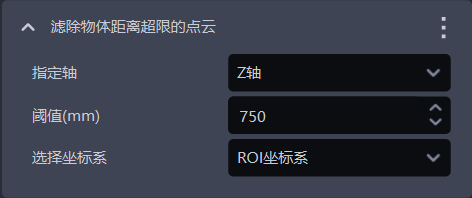
- Function
Filter out Point Cloud in the specified direction, remove noise, and improve the accuracy of image recognition.
- Parameter description * *
| Parameter | Description | Default value | Parameter range | unit | Parameter adjustment recommendation |
|---|---|---|---|---|---|
| specifies the axis | Point Cloud specifies the axis, used to filter out Point Cloud in the specified direction | Z axis | X/Y/Z axis | / | specifies the axis generally does not need to be changed |
| Threshold(mm) | In the specified axis direction, if the distance between the lower Point Cloud and the TargetPoint Cloud is greater than the Threshold, the lower Point Cloud will be filtered out; if the distance between the lower Point Cloud and the TargetPoint Cloud is less than the Threshold, the lower Point Cloud will be retained | 750 | [0, 1000] | mm | is adjusted according to the actual Scene. Threshold The smaller the Cloud; the smaller the Threshold, the more Point Clouds are filtered out |
| Select coordinate system | filters out Point Cloud in the selected coordinate system | ROI coordinate system | Camera coordinate system; ROI coordinate system; object own coordinate system | / |
- Example
2.1.12 Optimize mask according to Point Cloud

- Function
Based on the Point Cloud in ROI 3D, eliminate the Point Cloud in the mask that is not in ROI 3D to improve the accuracy of the mask.
2.2 pose estimation
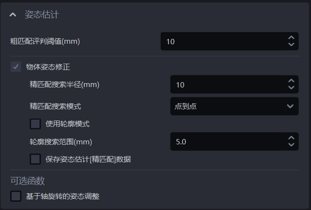
2.2.1 Coarse Matching Threshold(mm)

- Function
In the Coarse Matching process, the key points of the template Point Cloud are matched with the key points predicted by the model on the instance Point Cloud. If the average distance of the two sets of key points after matching is lower than the judgment Threshold, it is considered that the two sets of key points can match. If the average distance of the two sets of key points after matching is higher than the judgment Threshold, it is considered that the two sets of key points cannot match.
- Use Scene
Loading and unloading of neatly arranged general type target objects、Picking randomly arranged general type target objects、General Target positioned assemblyScene
- Parameter description * *
Default value: 10
Value range: [1, 1000]
Unit: mm
- Adjust parameters
Usually not changed
- Example
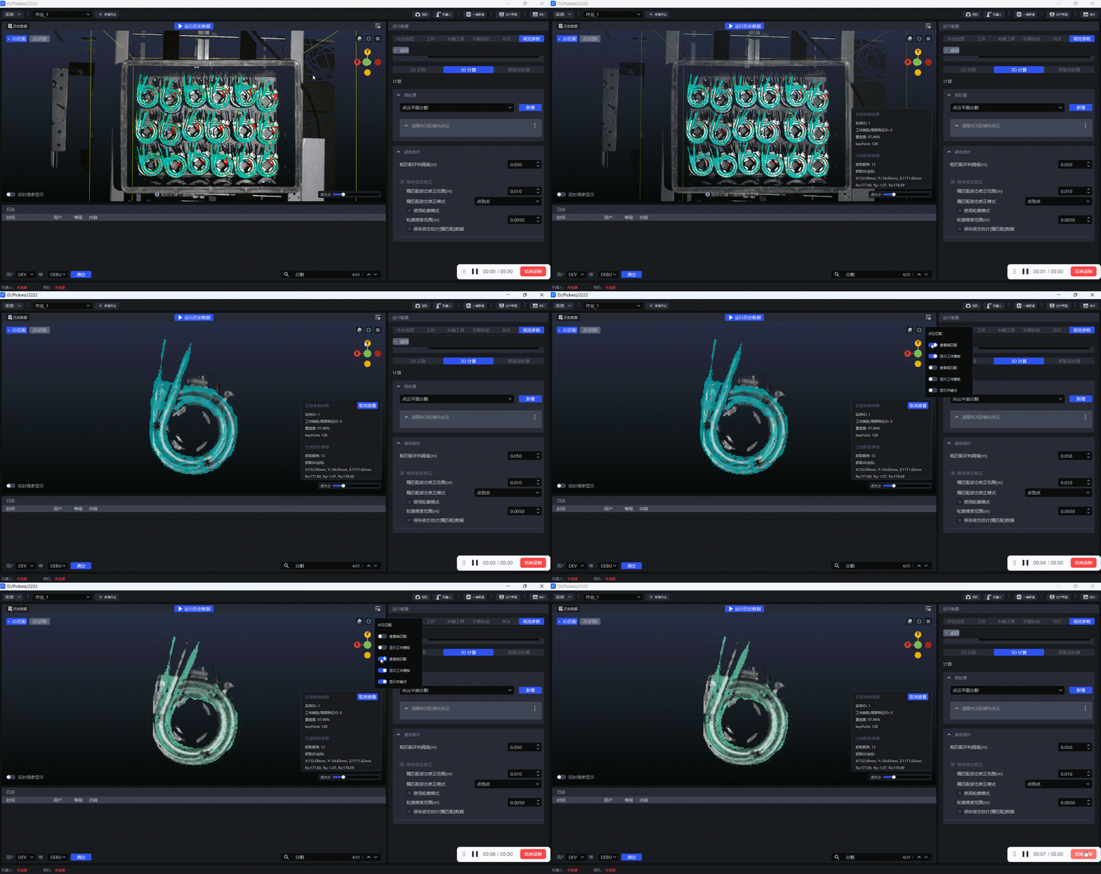
The results of Coarse Matching using key points can be viewed in the visualization window, as shown in the figure below.
2.2.2 object attitude correction
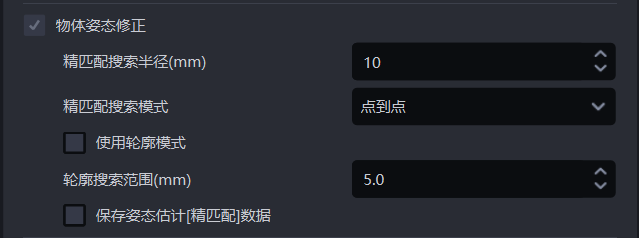
Fine matching search radius (mm)

- Function
In the fine matching process, the template Point Cloud is matched with the instance Point Cloud. Each point in the template Point Cloud needs to search for the nearest neighbor point in the instance Point Cloud. Fine matching search radius represents both the search radius in the instance Point Cloud and the distance Threshold between each point in the template Point Cloud and the nearest point in the instance Point Cloud. If the distance between a point and the nearest neighbor point is less than the Fine matching search radius, the two points are considered to be able to match, otherwise the two points are considered not to match.
- Use Scene
Loading and unloading of neatly arranged general type target objects、Picking randomly arranged general type target objects、General Target positioned assemblyScene
- Parameter description * *
Default value: 10
Value range: [1, 500]
Unit: mm
- Adjust parameters
Usually not changed
- Example
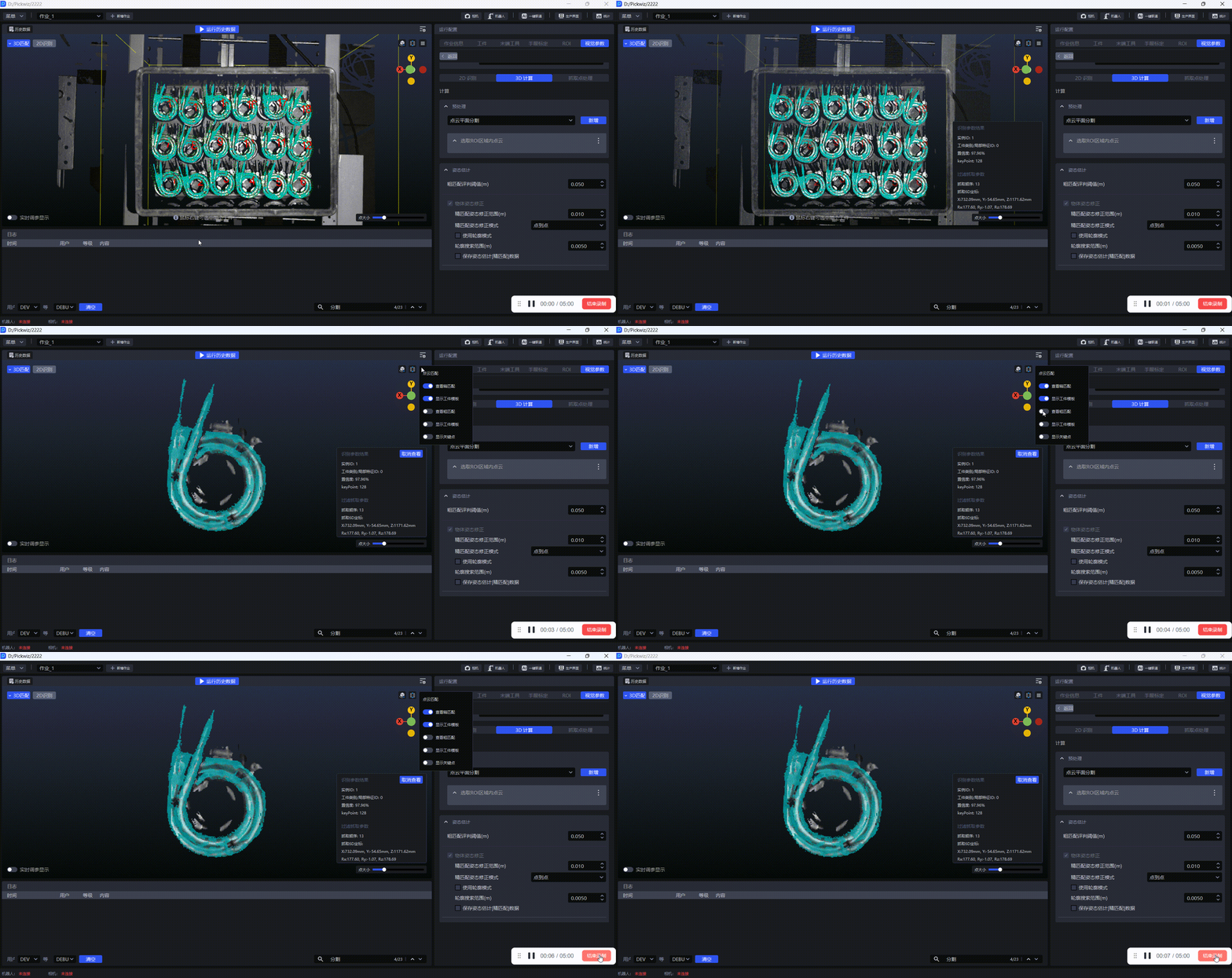
The Fine matching results can be viewed in the visualization window, as shown in the figure below.
Fine matching search mode

- Function
During the Fine matching process, the template Point Cloud searches for the closest point in the instance Point Cloud.
- Use Scene
The Fine matching result between template Point Cloud and instance Point Cloud is not good. This function should be adjusted.
- Parameter description * *
| Parameter | Description |
|---|---|
| point to point | Each point in the template Point Cloud searches for the nearest point in the instance Point Cloud (the point with the shortest straight line distance within the search radius). Applicable to all Targets |
| Point to point | Each point in the template Point Cloud searches for the nearest point in the instance Point Cloud along its normal vector. It is suitable for Targets with obvious geometric features. |
| Combination of point-to-point and point-to-surface methods | First use the point-to-point mode to optimize the Target posture in the instance Point Cloud, and then use the point-to-point mode to optimize the Target posture in the instance Point Cloud. It is suitable for Targets with obvious geometric features.
|
Use outline mode
- Function
Extract the contour Point Cloud in the template Point Cloud and instance Point Cloud for Coarse Matching
- Use Scene
Loading and unloading of neatly arranged general type target objects, Picking randomly arranged general type target objects, General Target positioned assemblyScene, if the results of using key points for Coarse Matching are not good, you should check this function and use the contour Point Cloud to perform Coarse Matching again.
- Adjust parameters
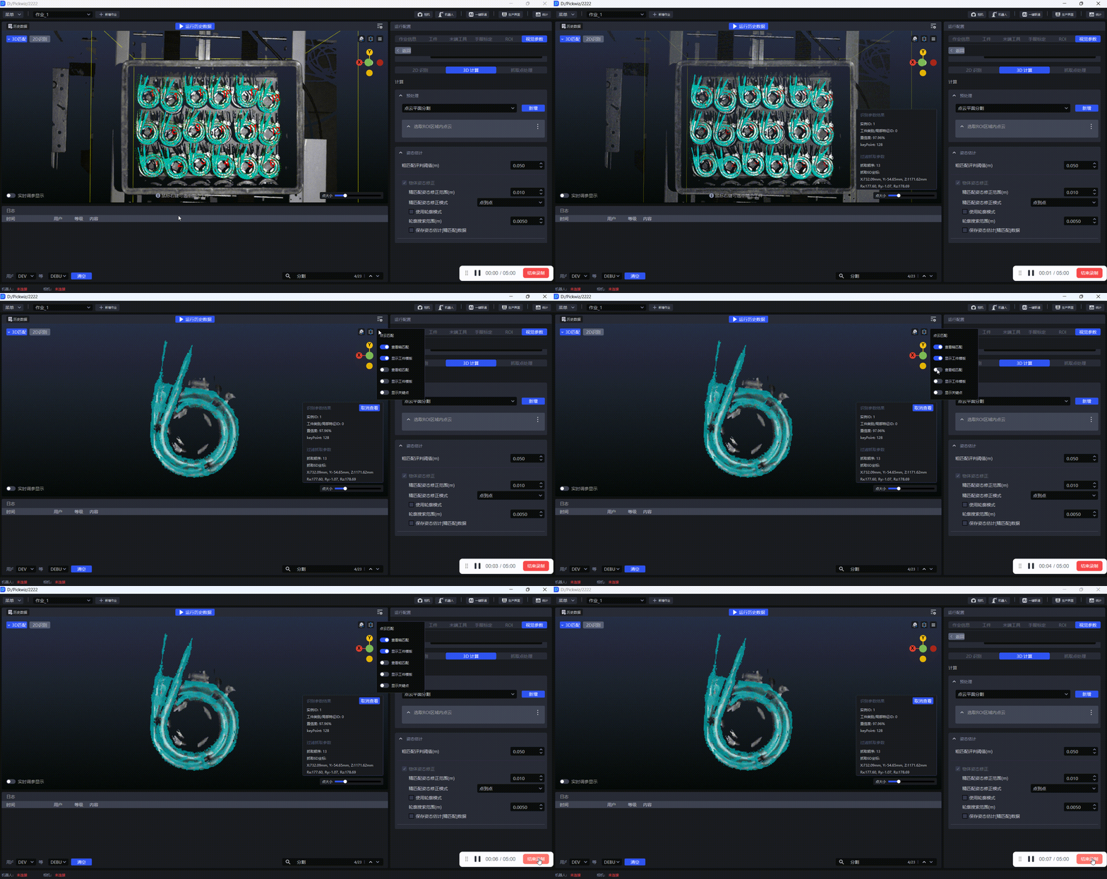
The results of Coarse Matching will affect the results of Fine matching. If the results of Fine matching are not good, you can check Use using outline
The Fine matching results can be viewed in the visualization window, as shown in the figure below.
Contour search range (mm)

- Function
Extract the search radius of the contour Point Cloud in the template Point Cloud and the instance Point Cloud
- Use Scene
Loading and unloading of neatly arranged general type target objects、Picking randomly arranged general type target objects、General Target positioned assemblyScene
- Parameter description * *
Default value: 5
Value range: [0.1, 500]
Unit: m
- Adjust parameters
If the value is smaller, the radius of the search contour Point Cloud is smaller, which is suitable for extracting detailed Target contours, but the extracted contours may contain outlier noise;
If the value is larger, the radius of the search contour Point Cloud is larger, which is suitable for extracting wider Target contours, but the extracted contours may ignore some detailed features.
Save pose estimation[Fine matching] data
- Function
If checked, Fine matching data will be saved.
- Use Scene
Loading and unloading of neatly arranged general type target objects、Picking randomly arranged general type target objects、General Target positioned assemblyScene
- Example
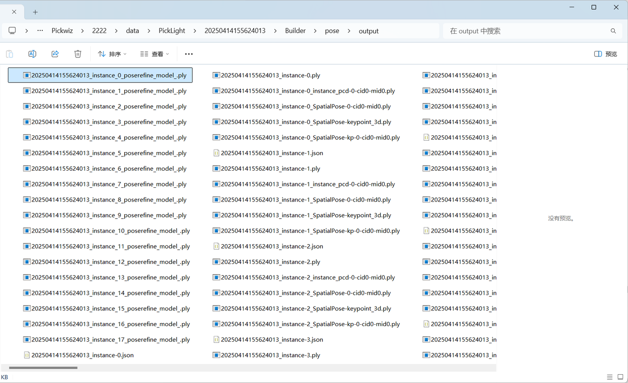
Fine matching data is saved in the project saving path \project folder\data\PickLight\historical data timestamp\Builder\pose\output folder.
2.2.3 Attitude adjustment based on axis rotation
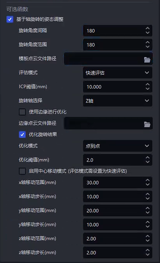
- Function
Rotate and translate the instance Point Cloud around a given axis based on the first Pick Point of the Target, calculate the matching score between the instance Point Cloud and the template Point Cloud after each rotation and translation, and select the instance Point Cloud with the highest matching score as the final posture of the rotationally symmetric Target.
- Use Scene
There is a deviation when the instance Point Cloud of the rotationally symmetric Target matches the template Point Cloud. It needs to be rotated at a certain angle to completely match.
Cannot be used in conjunction with Type Identification, Front-Back Identification (through Point Cloud template), and Local Identification of the function options
- Parameter description * *
| Parameter | Description | Default value | Parameter range | Parameter adjustment recommendation |
|---|---|---|---|---|
| rotation angle interval | Rotate the instance Point Cloud at equal intervals and calculate the angle difference between two adjacent rotations. For example, if the first rotation is 30°, the second rotation is 60°, and the third rotation is 90°, the rotation angle interval is 30°. | 5 | \[1, 180\] | If there are many Target features and it is difficult to match, and to pursue high-precision matching, you can set a smaller angular interval and perform more matches, but the amount of calculation will increase. If the target shape has few simple features, a larger angle interval can be set to improve calculation efficiency. |
| Rotation angle range | Starting from the initial state, the angle range of the instance Point Cloud can be rotated. | 90 | \[1, 180\] |
|
| Template PCD (Point Cloud Data) path | Upload Target's template PCD (Point Cloud Data). If not, use the Point Cloud template uploaded on the Target interface. | / | / | |
| Assessment mode | Evaluate the quality of matching results from different angles | Iso-target | Iso-target;Iso-source;Average;Strict;Loose;Fast |
|
| ICPThreshold | Criteria for judging whether registration is successful. If the error of the matching result is less than the Threshold, the match is successful. If the error of the matching result is greater than the Threshold, the match is unsuccessful. | 0.005 | \[0.000001, 1\] | Generally do not change. If the actual Scene has higher requirements for matching accuracy, adjust the Threshold smaller. If the actual Scene has higher requirements for matching speed but lower accuracy, increase the Threshold. If the TargetPoint Cloud quality is good, the Threshold can be adjusted smaller; if the TargetPoint Cloud quality is poor, the Threshold can be adjusted larger. |
| Rotation axis selection | The instance Point Cloud rotates around this axis | Z axis | X/Y/Z axis | Generally, no changes are made. If a certain axis of a rotationally symmetric Target is important for identifying the Target's posture, the rotation axis can be set as the characteristic axis. |
| Save visualization data | Whether to save visualization data | Uncheck | / | |
| Optimize using edges | Use Target's edge contour to optimize matching, reduce matching result errors, and make the matching between instance Point Cloud and template Point Cloud more precise. | Uncheck | / | If the edge contour of the target has unique geometric characteristics, check this function to improve the matching accuracy. For example, if the target has a complex shape and the edge contours are very different, the Point Cloud of the edge contour can be used to more accurately identify the target posture. |
| Edge PCD (Point Cloud Data) path | Upload the Target's edge PCD (Point Cloud Data). If not uploaded, extract the edge Point Cloud from the Point Cloud template uploaded on the Target interface. | / | / | |
| Optimize rotation results | During the matching process, the best posture is found and then optimized again to reduce the error in the matching results and make the matching between the instance Point Cloud and the template Point Cloud more precise. | Check | / | Checked by default to improve matching accuracy and generally not changed |
| Optimization mode | Patterns that optimize matching results | Point | Point;Plane;Full |
|
| Optimize Threshold | During the optimization process, it is judged whether the registration reaches the expected accuracy standard. If the registration error is less than the Threshold, the optimization is successful; if the registration error is greater than the Threshold, the optimization fails and needs to continue iteration. | 0.002 | \[0.0001, 1\] | Generally, do not change the Scene that requires higher registration accuracy, and adjust the Threshold smaller; for the Scene that requires lower registration accuracy, increase the Threshold. |
| Enable center movement mode | If turned on, the panning mode will be added at the same time, and the panning will be superimposed on the instance Point Cloud rotation. | Uncheck |
| |
| x-axis movement range | The range of movement of the center movement mode along the Pick Point x-axis (mm) | 0 | \[0,100\] |
|
| x-axis movement step size | The step size of the center movement mode along the Pick Point x-axis (mm) | 2 | \[0.01,10\] | The step size needs to be set appropriately based on the offset and accuracy. Setting the step size too small will cause the Cycle time to increase significantly |
| y-axis movement range | The range of movement of the center movement mode along the Pick Point y-axis (mm) | 0 | \[0,100\] |
|
| y-axis movement step size | The step size of the center movement mode along the Pick Point y-axis (mm) | 2 | \[0.01,10\] | The step size needs to be set appropriately based on the offset and accuracy. Setting the step size too small will cause the Cycle time to increase significantly |
| z-axis movement range | The range of movement of the center movement mode along the Pick Point z-axis (mm) | 0 | \[0,100\] |
|
| z-axis movement step size | The step size of the center movement mode along the Pick Point z-axis (mm) | 2 | \[0.01,10\] | The step size needs to be set appropriately based on the offset and accuracy. Setting the step size too small will cause the Cycle time to increase significantly |
- Example
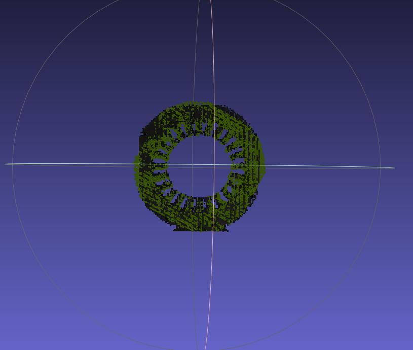
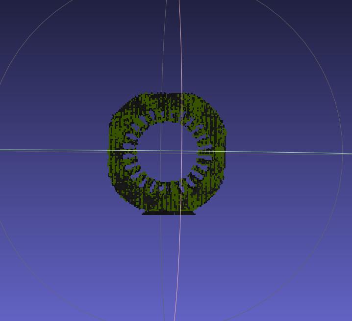

Axial matching offset

After adding center movement mode
- Explanation of the number of postures evaluated for posture adjustment based on axis rotation
The total number of posture calculations = the number of points moved on the x-axis * the number of points moved on the y-axis * z Number of points for axis movement * Number of points for angle
If the movement range is too large or the step size is set too small, the total number of postures to be evaluated will increase, and the cycle time will become longer. The range and step size Parameter need to be set appropriately
2.3 empty ROI judgment

- Function
Determine whether there is Target (Point Cloud) remaining in ROI 3D. If ROI If the number of 3D points in 3D is less than this value, it means that there is no TargetPoint Cloud remaining, and the Point Cloud will not be returned at this time.
- Parameter description * *
Default value: 1000
Value range: [0, 100000]
- Usage process
Set the minimum number of ROI 3D points to determine the Threshold. If it is less than the Threshold, it is the ROI. There is insufficient TargetPoint Cloud in 3D, so it is judged that there is no Target in ROI 3D;
In the Robot configuration, a new visual status code is added to facilitate subsequent signal processing by the Robot.
3. Pick Point
This section mainly explains functions related to Pick Point filtering and adjustment, along with Parameter tuning recommendations.
3.1 Pick Point Adjustment
3.1.1 Bound Euler Angle
- Function description
When the Picking Pose is outside the configured angle range, it is rotated counterclockwise by a certain angle around a fixed axis. If it is still outside the configured angle range after rotation, a warning is issued.
- Usage scenario
This function is only applicable to depalletizing scenarios. It can keep the robot's approach direction stable during picking and prevent the end effector from repeatedly rotating during the picking process. In 180° cases, it can prevent exceptions such as cable twisting.
- Parameter description
| Parameter | Description | Default | Range | Unit |
|---|---|---|---|---|
| Fixed axis | An axis of the Picking Pose. The pose is rotated counterclockwise around this fixed axis | Z-axis | X/Y/Z-axis | / |
| Rotation angle | The angle by which the pose is rotated counterclockwise around the fixed axis. Adjust this angle so the Picking Pose satisfies the angle range | 0 | [-360,360] | degree |
| Angle range | The angle range of the Picking Pose. Set the angle range according to factors such as material placement, end effector type, and cycle time | [0,180] | [-180,180] | degree |
| Use current robot Euler Angles | By default, pose calculation uses Euler Angles "XYZ". When selected, the Euler Angles configured for the current robot are used so the pose remains consistent with the robot teach pendant. | Unchecked | / | / |
| Custom coordinate system | The coordinate system of the Picking Pose | Robot arm coordinate system | Default coordinate system; camera coordinate system; ROI coordinate system; robot arm coordinate system | / |
- Example
Without using this function, the generated Pick Points are shown below.
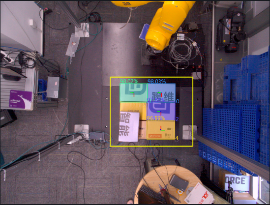
When this function is used with the default values, the RZ angles of the Picking Poses for instances 0, 1, and 2 are all within the angle range [0,180], so no processing is performed. The RZ angle of the Picking Pose for instance 4 is -90°, which is outside the angle range [0,180], so the Picking Pose of instance 4 is rotated by 0° around the fixed Z-axis.
If you want to adjust the RZ angle of the Picking Pose for instance 4 into the angle range, you can change the rotation angle to 180 and rotate the Picking Pose of instance 4 by 180° around the fixed Z-axis.
3.1.2 Rotate the pose to align the rotation axis direction with the target axis direction
- Function description
Rotate the Picking Pose once around the fixed axis so that the direction of the rotation axis (determined by the right-hand rule) matches the positive or negative direction of the target axis in the target coordinate system.
- Usage scenario
Avoid collisions between the robot end effector and the bin.
- Parameter description
| Parameter | Description | Default | Range |
|---|---|---|---|
| Rotation axis | An axis of the Picking Pose. Determined by the right-hand rule, the Picking Pose is rotated counterclockwise once around the fixed axis so that the direction of the rotation axis matches the positive or negative direction of the target axis in the target coordinate system | X-axis | X/Y/Z-axis |
| Fixed axis | The Picking Pose is rotated counterclockwise once around the fixed axis so that the direction of the rotation axis matches the positive or negative direction of the target axis in the target coordinate system | Z-axis | X/Y/Z-axis |
| Target axis | An axis of the target coordinate system. The Picking Pose is rotated counterclockwise once around the fixed axis so that the direction of the rotation axis matches the positive or negative direction of the target axis in the target coordinate system | X-axis | X/Y/Z-axis |
| Negative target axis direction | If selected, the direction of the rotation axis is aligned with the negative direction of the target axis in the target coordinate system; otherwise, it is aligned with the positive direction of the target axis in the target coordinate system | Unchecked | / |
| Custom coordinate system | The coordinate system of the Picking Pose | Default coordinate system | Default coordinate system; camera coordinate system; ROI coordinate system; robot arm coordinate system |
3.1.3 Rotate Pose to Align Axis
- Function description
Rotate the Picking Pose around the fixed axis by 0, 90, 180, and 270 degrees respectively, calculate the angle between the rotated rotation axis and the positive or negative direction of the target axis in the camera coordinate system, and finally output the Picking Pose with the smallest angle after rotation.
- Usage scenario
Avoid collisions between the robot end effector and the bin.
- Parameter description
| Parameter | Description | Default | Range |
|---|---|---|---|
| Fixed axis | An axis of the Picking Pose. Rotate the pose counterclockwise around this fixed axis | Z-axis | X/Y/Z-axis |
| Rotation axis | An axis of the Picking Pose. When rotating the pose, calculate the angle between this rotation axis and the positive or negative direction of the target axis | X-axis | X/Y/Z-axis |
| Target axis | An axis of the camera coordinate system. When rotating the pose, calculate the angle between the rotation axis and the positive or negative direction of this target axis | X-axis | X/Y/Z-axis |
| Negative target axis direction | If selected, calculate the angle between the rotation axis and the negative direction of the target axis; otherwise, calculate the angle between the rotation axis and the positive direction of the target axis | Selected | / |
| Custom coordinate system | The coordinate system of the Picking Pose | Default coordinate system | Default coordinate system; camera coordinate system; ROI coordinate system; robot arm coordinate system |
- Example
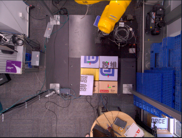
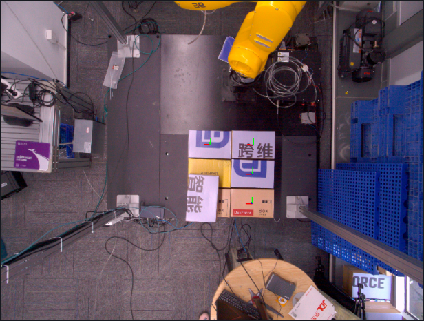
3.1.4 Flip Pose to Align Axis
- Function description
Rotate the Picking Pose once around the fixed axis so that the angle formed between the rotation axis and the positive or negative direction of the target axis in the ROI coordinate system is acute.
- Usage scenario
Avoid collisions between the robot end effector and the bin.
- Parameter description
| Parameter | Description | Default | Range |
|---|---|---|---|
| Fixed axis | An axis of the Picking Pose. Rotate the Picking Pose counterclockwise around this fixed axis | Z-axis | X/Y/Z-axis |
| Rotation axis | An axis of the Picking Pose. Rotate the Picking Pose so that the direction of this rotation axis matches the positive or negative direction of the target axis | X-axis | X/Y/Z-axis |
| Target axis | An axis in the ROI coordinate system. Rotate the Picking Pose so that the direction of the rotation axis matches the positive or negative direction of this target axis | X-axis | X/Y/Z-axis |
| Negative target axis direction | If selected, rotate the Picking Pose so that the direction of the rotation axis matches the negative direction of the target axis; otherwise, rotate the Picking Pose so that the direction of the rotation axis matches the positive direction of the target axis | Selected | / |
| Custom coordinate system | The coordinate system of the Picking Pose | Default coordinate system | Default coordinate system; camera coordinate system; ROI coordinate system; robot arm coordinate system |
- Example
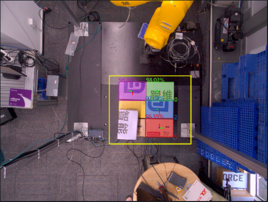
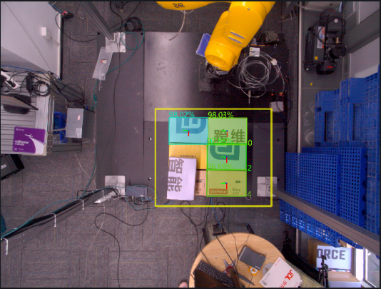
3.1.5 Flip Axis to ROI Center
- Function
Rotate the Picking Pose around a fixed axis so that the pointing axis of the Picking Pose points to the ROI center.
- Usage scenario
Avoid collisions between the robot end effector and the bin.
- Parameter description
| Parameter | Description | Default | Range |
|---|---|---|---|
| Pointing axis | The axis in the Picking Pose that needs to be adjusted | X-axis | X/Y/Z-axis |
| Fixed axis | The axis that remains unchanged during rotation | Z-axis | X/Y/Z-axis |
| Reverse align | If selected, reverse-align the pointing axis to the ROI center; otherwise, align the pointing axis to the ROI center | Selected | / |
| Strict pointing | If selected, force the Picking Pose to rotate so the pointing axis points to the ROI center | Unchecked | / |
| Custom coordinate system | The coordinate system of the Picking Pose | Default coordinate system | Default coordinate system; camera coordinate system; ROI coordinate system; robot arm coordinate system |
- Example
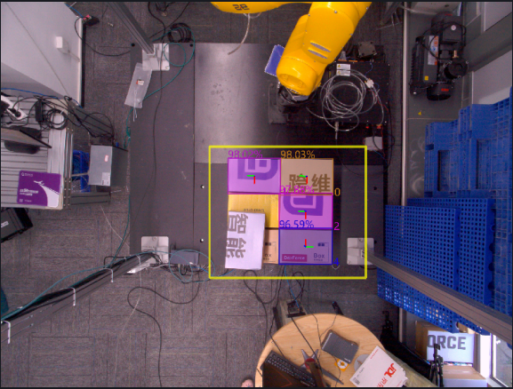
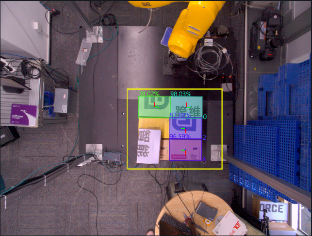
3.1.6 Transform to Target Pose
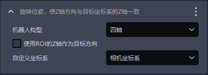
- Function description
Rotate the Picking Pose so that its Z-axis direction matches the Z-axis of the target coordinate system.
- Usage scenario
Usually this is used by default only in depalletizing scenarios and cannot be deleted. It is used to make the Z-axis of the Picking Pose perpendicular to the Z-axis of the ROI coordinate system (4-axis) or consistent with the direction of the Target Object surface (6-axis).
- Parameter description
| Parameter | Description | Default | Range |
|---|---|---|---|
| Robot configuration | Set according to the on-site robot configuration. You can choose 4-axis or 6-axis. If a 6-axis robot is actually used as a 4-axis robot, it should be set to 4-axis | 4-axis | 4-axis/6-axis |
| Use ROI Z-axis as target direction | When the robot configuration is set to 4-axis, if selected, the pose is rotated around the X-axis so that the Z-axis direction of the rotated pose matches the positive direction of the ROI Z-axis ; if not selected, the pose is rotated around the X-axis so that the Z-axis direction of the rotated pose matches the positive direction of the Z-axis of the camera coordinate system . When the robot configuration is set to 6-axis, regardless of whether it is selected, the pose is rotated around the X-axis so that the Z-axis direction of the rotated pose matches the positive direction of the Z-axis of the object's own coordinate system | Unchecked | / |
| Custom coordinate system | The coordinate system of the Picking Pose | Camera coordinate system | Default coordinate system; camera coordinate system; ROI coordinate system; robot arm coordinate system |
- Example
3.1.7 Rotate Pose with Angle
- Function description
Rotate the Picking Pose by a certain angle around a fixed axis.
- Usage scenario
Avoid collisions between the robot end effector and the bin.
- Parameter description
| Parameter | Description | Default | Range | Unit |
|---|---|---|---|---|
| Rotation angle | The angle by which the pose is rotated counterclockwise around the fixed axis | 90 | [-360, 360] | degree° |
| Fixed axis | An axis of the Picking Pose. Rotate the pose counterclockwise around this fixed axis | Z-axis | X/Y/Z-axis | / |
| Custom coordinate system | The coordinate system of the Picking Pose | Default coordinate system | Default coordinate system; camera coordinate system; ROI coordinate system; robot arm coordinate system | / |
- Example
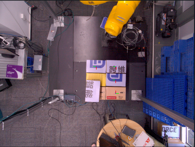
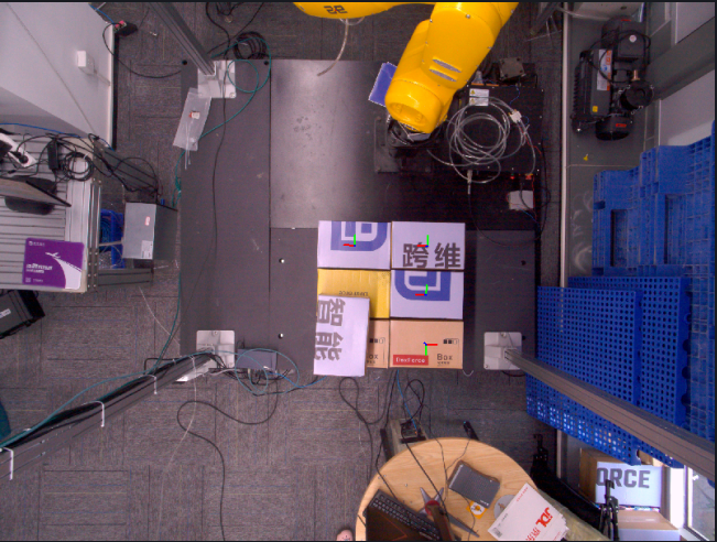
3.1.8 Move Pose With Offset
- Function description
Move the Picking Pose by a certain distance along the translation axis.
- Usage scenario
Avoid collisions between the robot end effector and the bin.
- Parameter description
| Parameter | Description | Default | Range | Unit |
|---|---|---|---|---|
| Translation amount (mm) | The distance the Picking Pose moves along the translation axis. A positive translation amount means translating in the positive direction of the translation axis, and a negative translation amount means translating in the negative direction of the translation axis | 0 | [-1000, 1000] | mm |
| Translation axis | The direction in which the Picking Pose moves | X-axis | X/Y/Z-axis | / |
| Custom coordinate system | The coordinate system of the Picking Pose | Robot arm coordinate system | Default coordinate system; camera coordinate system; ROI coordinate system; robot arm coordinate system | / |
- Example
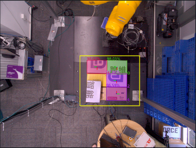
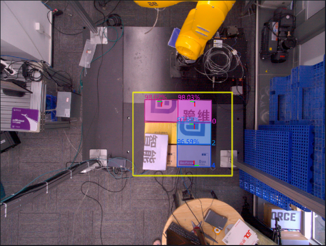
3.1.9 Transform Pose by Difference
- Function description
Record the Pick Point coordinates generated by the software and the Pick Point coordinates taught under the current operating condition, then output the transformed Picking Pose based on the offset between the two.
- Usage scenario
When the Pick Points generated by the vision system have an obvious systematic offset and the robot TCP coordinate accuracy is limited or difficult to calibrate, this method can be used to directly map the same offset pattern to subsequent Pick Points, thereby avoiding robot TCP calibration.
- Parameter description
| Parameter | Description | Default | Range |
|---|---|---|---|
| Vision Pose | Pick coordinates of the detection result | ||
| X(mm) | X coordinate of the Vision Pose | 0.00 | ±10000000, meaning no limit. |
| Y(mm) | Y coordinate of the Vision Pose | 0.00 | ±10000000, meaning no limit. |
| Z(mm) | Z coordinate of the Vision Pose | 0.00 | ±10000000, meaning no limit. |
| RX(°) | X-axis rotation amount of the Vision Pose | 0.00 | ±180 |
| RY(°) | Y-axis rotation amount of the Vision Pose | 0.00 | ±180 |
| RZ(°) | Z-axis rotation amount of the Vision Pose | 0.00 | ±180 |
| Picking Pose | Manually taught Pick Point | ||
| X(mm) | X coordinate of the Picking Pose | 0.00 | ±10000000, meaning no limit. |
| Y(mm) | Y coordinate of the Picking Pose | 0.00 | ±10000000, meaning no limit. |
| Z(mm) | Z coordinate of the Picking Pose | 0.00 | ±10000000, meaning no limit. |
| RX(°) | X-axis rotation amount of the Picking Pose | 0.00 | ±180 |
| RY(°) | Y-axis rotation amount of the Picking Pose | 0.00 | ±180 |
| RZ(°) | Z-axis rotation amount of the Picking Pose | 0.00 | ±180 |
3.1.10 Refine Pose by Plane Normal
- Function description
Correct the Object Pose by fitting the plane Normal so that the Z-axis direction of the Object Pose remains consistent with the direction of the plane Normal of the Target Object.
- Usage scenario
When the Target Object contains a plane and there is a tilt deviation in the plane when the template Point Cloud is matched with the actual Point Cloud, use this function to fine-tune the Target Object plane and improve picking accuracy.
Not applicable to depalletizing scenarios
- Parameter description
| Parameter | Description | Default | Range | Unit |
|---|---|---|---|---|
| Distance Threshold | Distance Threshold for fitting a plane from the Point Cloud | 10 | [-1000, 1000] | mm |
| Save visualization data | If selected, the visualization data will be saved under the historical data timestamp | Selected | / | / |
| Custom coordinate system | The coordinate system of the Picking Pose | Camera coordinate system | Default coordinate system; camera coordinate system; ROI coordinate system; robot arm coordinate system | / |
- Example
3.1.11 Sort Pick Points by Angle with ROI Axis
- Function
Sort Pick Points according to the angle between an axis of the Picking Pose and the target axis of the ROI.
- Parameter description
| Parameter | Description | Default | Range |
|---|---|---|---|
| Axis selection | An axis of the Picking Pose | Z-axis | X/Y/Z-axis |
| Target axis selection | An axis of the ROI coordinate system | Z-axis | X/Y/Z-axis |
| Select reverse direction | If selected, calculate the angle with the negative direction of the target axis; otherwise, calculate the angle with the positive direction of the target axis | Unchecked | / |
| Select descending order | If selected, sort Pick Points from small to large by angle; otherwise, sort Pick Points from large to small by angle | Unchecked | / |
3.1.12 [Advanced] Rotate Pose, Automatically Compensate for Grasp Orientation Angles with Excessive Deviation from the Specified Axis
- Function description
Determine whether the angle formed between the specified axis of the Picking Pose and the target axis is within the specified range. If not, adjust the Picking Pose into the specified range.
- Usage scenario
Avoid collisions between the robot end effector and the bin.
- Parameter description
| Parameter | Description | Default | Range | Unit |
|---|---|---|---|---|
| Angle range | Adjust the Picking Pose into the angle range | 30 | [0, 180] | degree° |
| Specified axis | An axis of the Picking Pose. Adjust this axis so that it falls within the angle range relative to the target axis of the ROI coordinate system | Z-axis | X/Y/Z-axis | / |
| Target axis | An axis of the ROI coordinate system. Compare the angle range with the specified axis of the Picking Pose | Z-axis | X/Y/Z-axis | / |
| Compare with the negative half-axis of the ROI | If not selected, compare the angle range with the positive direction of the target axis of the ROI coordinate system; if selected, compare the angle range with the negative direction of the target axis of the ROI coordinate system | Unchecked | / | / |
| Custom coordinate system | The coordinate system of the Picking Pose | Default coordinate system | Default coordinate system; camera coordinate system; ROI coordinate system; robot arm coordinate system | / |
3.1.13 [Advanced] Symmetry Center Pose Optimization
- Function
Search for the symmetry center of the Target Object based on the instance Mask, then combine it with the plane of the instance or the pose of the ROI 3D center point to calculate the optimal Picking Pose.
Before using this function, first make sure the instance Mask is symmetrical
- Usage scenario
Applicable when the instance Mask of a symmetrical Target Object is also symmetrical, but the Picking Pose is not near the expected center; at the same time, the Target Object has a plane that can be used as a reference, for example, there is a plane on the top of the object, or ROI 3D can be used as a reference for the projected pose.
Applicable project scenarios include brake discs (general circles), refractory bricks (depalletizing), symmetrical irregular parts, fuel fillers, and so on.
- Parameter description
| Parameter | Description | Default | Range | Tuning recommendation |
|---|---|---|---|---|
| Target Object Symmetry type | Target Object Symmetry type of the instance Mask | Rotational symmetry | Rotational symmetry: after the Target Object rotates by a certain angle around the center point, its shape completely overlaps with the original position; mirror symmetry: the Target Object uses a certain axis / plane as the mirror, and the left-right or upper-lower sides are completely symmetrical. | Circles and rectangles are both rotationally symmetrical and mirror-symmetrical, so rotational symmetry is preferred; for trapezoids and other shapes that are symmetrical only along a certain axis or plane, choose mirror symmetry. |
| Gaussian blur level | Tolerance for determining whether the actual Point Cloud overlaps after rotation | 3 | \[1,99\] |
|
| Rotation angle setting | When the symmetry mode is rotational symmetry, it indicates the rotation angle interval, that is, the angle difference between two adjacent rotations. When the symmetry mode is mirror symmetry, it indicates the rotation range, that is, the angle interval within which the Point Cloud can rotate around the symmetry axis. | 180 | \[1,360\] |
|
| Image scaling ratio | Adjusts the size of the Point Cloud image. The larger this ratio, the smaller the Point Cloud image size and the lower the GPU memory usage, but image detail loss increases, resulting in reduced calculation accuracy . | 2 | \[1,10000000\] | |
| Search range | Based on the initially determined center of the Target Object, this defines the range expanded outward to search for Point Cloud features. The actual range is (search range*2*image scaling ratio) | 10 | \[1,10000000\] | For example, for a square Target Object, the initially determined center position of the Target Object is point O. If the search range is set to 10 and the image scaling ratio is 1, then the actual search range is a square region centered at point O with a side length of 10×2×1=20. Point Cloud features are searched within this region to further determine the symmetry center of the Target Object and the optimal Picking Pose. As another example, for a circular Target Object, if the search range is set to 8 and the image scaling ratio is 2, then the actual search range is a circular region centered at the initially determined center of the Target Object with a diameter of 8×2×2=32. Point Cloud features are searched within this region to further determine the Object Pose of the Target Object and the optimal Picking Pose. |
| Use ROI3D as the reference projection plane | If selected, ROI3D is used as the reference projection plane | Unchecked | / | Select this when the Point Cloud has no obvious plane and the projection plane is difficult to determine; leave it unchecked when the Point Cloud has a clear plane. |
| Save symmetry center process data | If selected, the debug data generated during the symmetry center process is saved. You can view it in the `\ProjectName`\data`\PickLight`\HistoricalDataTimestamp`\find`\_symmetry_center folder | Unchecked | / | Select this when you need to inspect the detailed process images |
| Symmetry axis prior type | Effective in ``{=html}mirror symmetry``{=html} mode. Specifies the known Target Object Symmetry type and fixes the asymmetric orientation | Automatic search | Automatic searchSymmetric along the long axisSymmetric along the short axis | If the symmetry axis of the Target Object is the long axis, choose "Symmetric along the long axis". If the symmetry axis of the Target Object is the short axis, choose "Symmetric along the short axis". If uncertain, choose "Automatic search" |
| Pose adjustment type | Whether to inherit pose-related information from the input pose | Default pose | Default poseInherit rotationInherit translation | / |
| Symmetry score Threshold | Symmetry results with a symmetry score lower than this Threshold are abnormal results. When set to 0, no filtering is performed | 0.0 | \[0.0, 1.0\] | / |
- Example
3.2 Pick Point Filtering
3.2.1 Filter by Fine Matching Score
- Function description
Filter Pick Points based on the pose fine matching score.
- Parameter description
| Parameter | Description | Default | Range |
|---|---|---|---|
| Score Threshold | Retain Pick Points whose fine matching score is greater than this Threshold | 0.5 | [0, 1] |
3.2.2 Filter grasp points of occluded artifacts
- Function description
Determine whether there are too many occluding object Point Clouds in the target detection area along the specified ROI axis or the Picking Pose axis at the Pick Point of the grasped Target Object. If so, the Target Object is considered occluded and the Pick Point is filtered out.
- Usage scenario
Applicable to depalletizing and ordered scenarios in which Target Objects are picked layer by layer, but the model recognizes lower-layer Target Objects. When picking a lower-layer Target Object, the gripper may collide with the upper-layer Target Object.
- Parameter description
| Parameter | Description | Default | Range | Unit |
|---|---|---|---|---|
| Cuboid length in X direction | Set the cuboid length in the X direction of the Picking Pose | 1500 | [1, 10000] | mm |
| Cuboid length in Y direction | Set the cuboid length in the Y direction of the Picking Pose | 1500 | [1, 10000] | mm |
| Cuboid length in Z direction | Set the cuboid length in the Z direction of the Picking Pose | 800 | [1, 10000] | mm |
| Distance Threshold between detection area and Pick Point origin | Along the ROI axis, the nearby cuboid surface area farther than this distance Threshold from the Pick Point origin is regarded as the target detection area | 50 | [1, 1000] | mm |
| Point Cloud count Threshold in detection area | If the number of occluding object Point Clouds in the target detection area exceeds this Threshold, the Pick Point is considered occluded | 1000 | [0, 100000] | / |
| Specified axis direction | Based on the pose reference specified axis direction, set the specific location of the target detection area within the cuboid space (for example, near the front/back/left/right/top/bottom surface of the cuboid) | [0,0,-1] | [1,0,0]: positive X-axis[-1,0,0]: negative X-axis[0,1,0]: positive Y-axis[0,-1,0]: negative Y-axis[0,0,1]: positive Z-axis[0,0,-1]: negative Z-axis | / |
| Use ROI 3D pose reference | If selected, adjust the collision detection area according to the ROI 3D pose reference | Unchecked | / | / |
| Save visualization data | If selected, the visualization data is stored according to the saved data path to help observe whether the generated cuboid is reasonable; if not selected, it is not saved | Unchecked | / | / |
3.2.3 Filter Pose by Cone
- Function description
Determine whether the angle of the Picking Pose is within the constrained angle range, and filter out all Pick Points that do not meet the condition.
- Usage scenario
Prevent collisions caused by abnormal robot arm Picking Pose angles.
- Parameter description
| Parameter | Description | Default | Range | Unit |
|---|---|---|---|---|
| Angle filtering Threshold | Calculate the maximum angle between the specified axis of the ROI and the specified axis of the Picking Pose. Pick Points whose angle is greater than the current Threshold will be filtered out | 30 | [-360, 360] | degree° |
| Invert ROI specified axis direction | If selected, use the negative direction of the specified ROI axis for angle calculation; otherwise, use the positive direction of the specified ROI axis for angle calculation | Selected | / | / |
| Specified Picking Pose axis | Specify an axis of the Picking Pose for angle calculation | Z-axis | X/Y/Z-axis | / |
| Specified ROI axis | Specify an axis of the ROI coordinate system for angle calculation | Z-axis | X/Y/Z-axis | / |
3.2.4 Filter Pick Points outside the ROI 3D type area
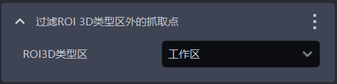
- Function description
Determine whether the Pick Point is within the ROI 3D range, and remove Pick Points that are outside the ROI 3D area.
- Usage scenario
Prevent picking outside the ROI area, which may cause collisions between the robot arm and the target object.
- Parameter description
| Parameter | Description | Default |
|---|---|---|
| ROI3D type region | Usually "workspace"; "pick area" is a smaller ROI region than "workspace", which can restrict Pick Points to an ROI region smaller than the "workspace" to avoid some collision cases. | Workspace |
- Example
As shown in the figure below, when the ROI3D area and ROI2D are area a, the corresponding Pick Point is in the upper-right corner.
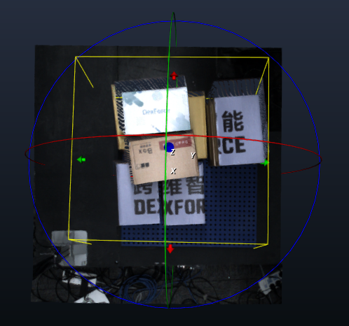
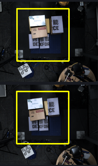
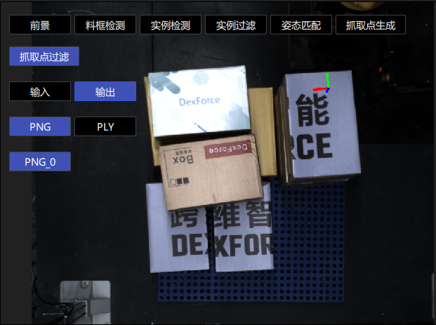
When the ROI3D area and ROI2D are changed to area b, the original Pick Point is outside the ROI area, so that Pick Point is removed and a new Pick Point is generated within area b.
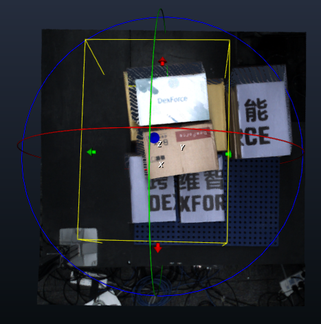
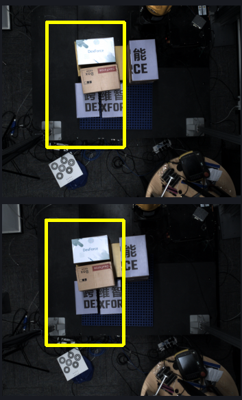
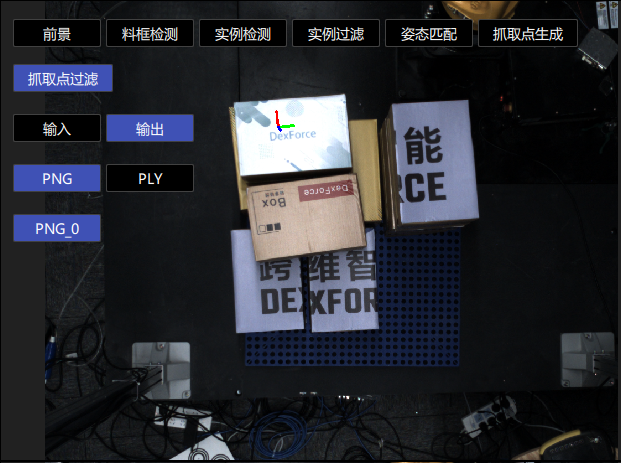
3.2.5 [New] Gripper Collision Detection
[New] Gripper Collision Detection
- Function description
Collision detection between the gripper and the Point Cloud near the Pick Point. If the number of Point Clouds in contact with the gripper exceeds the pick collision Threshold, the Pick Point of the Target Object is considered to have a collision risk.
- Usage scenario
Used when collision detection is required between the gripper and the Point Cloud near the Target Object being picked.
- Parameter description
| Parameter | Description | Default | Range |
|---|---|---|---|
| Collision Threshold | Collision distance Threshold. If the distance between the scene and the gripper surface is smaller than this Threshold, it is considered a collision. The larger the Threshold, the stricter it is. Unit: mm | 7 | 1-1000 |
| Collision Point Cloud sampling | Sampling size for collision Point Clouds. The larger the value, the faster the cycle time; the smaller the value, the slower the cycle time. Effective only in "Target Object scene Point Cloud only" and "bin + Target Object scene Point Cloud" modes. Unit: mm | 5 | 1 - 1000 |
| Save visualization data for gripper collision detection | Save visualization data for collision detection between the gripper and the picked Target Object | Unchecked | Selected/Unchecked |
Gripper Collision Detection
- Function description
Collision detection between the gripper and the Point Cloud near the Pick Point. If the number of Point Clouds in contact with the gripper exceeds the pick collision Threshold, the Pick Point of the Target Object is considered to have a collision risk.
- Usage scenario
Used when collision detection is required between the gripper and the Point Cloud near the Target Object being picked.
- Parameter description
| Parameter | Description | Default | Range |
|---|---|---|---|
| Pick collision Threshold | The maximum number of Point Clouds the gripper may contain near the Pick Point. For example, 20 means that if the number of scene Point Clouds contained by the gripper exceeds 20, it is considered a collision | 20 | 0-10000 |
| Collision Point Cloud sampling (m) | Downsampling size of the Point Cloud in the collision area. The larger the value, the faster the detection speed, but the lower the accuracy. Applicable scenario: scenarios requiring high cycle rates | 0.002 | 0.0001 - 0.5000 |
| Save visualization data for gripper collision detection | Save visualization data for collision detection between the gripper and the picked Target Object | Unchecked | Selected/Unchecked |
| Import gripper model | Select and import the gripper model used for collision detection from a folder | / | / |
**The gripper should be simplified to fewer than 500 faces**
3.2.6 [Master] Retain the one Pick Point with the largest/smallest pose value among instance Pick Points and filter the remaining Pick Points
- Function description
Convert the pose to the specified coordinate system, sort poses according to the value of the specified sorting axis, and retain the pose with the maximum or minimum value. This is suitable for cylindrical Target Objects when keeping the top or bottom Pick Point.
- Parameter description
| Parameter | Description | Default | Range |
|---|---|---|---|
| Specified coordinate system | Select which coordinate system the pose should be converted to for processing | ROI coordinate system | ROI coordinate system/camera coordinate system |
| Specified sorting axis | Select which axis value of the pose to sort by | Z-axis | X/Y/Z-axis |
| Take minimum value | If selected, retain the pose with the minimum value on the sorting axis; otherwise, retain the pose with the maximum value on the sorting axis | Unchecked | / |
3.2.7 [Master] Filter grasp points similar to the previous N grasp points
- Function description
If the variation between the current Pick Point and any Pick Point in the cache is within the Threshold range, the Pick Point will be filtered out.
- Parameter description
| Parameter | Description | Default | Range | Unit |
|---|---|---|---|---|
| Upper limit of Pick Point change (+) | ||||
| X(mm) | Upper limit of X coordinate | 2 | [0, 10000000] | mm |
| Y(mm) | Upper limit of Y coordinate | 2 | [0, 10000000] | mm |
| Z(mm) | Upper limit of Z coordinate | 2 | [0, 10000000] | mm |
| RX(°) | Upper limit of RX rotation amount | 1 | [0, 180] | degree° |
| RY(°) | Lower limit of RY rotation amount | 1 | [0, 180] | degree° |
| RZ(°) | Lower limit of RZ rotation amount | 1 | [0, 180] | degree° |
| Lower limit of Pick Point change (-) | ||||
| X(mm) | Lower limit of X coordinate | 2 | [0, 10000000] | mm |
| Y(mm) | Lower limit of Y coordinate | 2 | [0, 10000000] | mm |
| Z(mm) | Lower limit of Z coordinate | 2 | [0, 10000000] | mm |
| RX(°) | Lower limit of RX rotation amount | 1 | [0, 180] | degree° |
| RY(°) | Lower limit of RY rotation amount | 1 | [0, 180] | degree° |
| RZ(°) | Lower limit of RZ rotation amount | 1 | [0, 180] | degree° |
| Pick Point cache count | Number of Pick Points cached. After the current Pick Point comparison is completed, it will be added to the cache in real time | 5 | [1, 100] | / |
3.2.8 [Master] Filter artifact poses similar to the previous N artifact poses
- Function description
If the variation between the current Object Pose and any Object Pose in the cache is within the Threshold range, the Object Pose will be filtered out. When an Object Pose is determined to be similar, all Pick Points on that Target Object will be filtered out.
- Parameter description
| Parameter | Description | Default | Range | Unit |
|---|---|---|---|---|
| Upper limit of Object Pose change (+) | ||||
| X(mm) | Upper limit of X coordinate | 2 | [0, 10000000] | mm |
| Y(mm) | Upper limit of Y coordinate | 2 | [0, 10000000] | mm |
| Z(mm) | Upper limit of Z coordinate | 2 | [0, 10000000] | mm |
| RX(°) | Upper limit of RX rotation amount | 1 | [0, 180] | degree° |
| RY(°) | Lower limit of RY rotation amount | 1 | [0, 180] | degree° |
| RZ(°) | Lower limit of RZ rotation amount | 1 | [0, 180] | degree° |
| Lower limit of Object Pose change (-) | ||||
| X(mm) | Lower limit of X coordinate | 2 | [0, 10000000] | mm |
| Y(mm) | Lower limit of Y coordinate | 2 | [0, 10000000] | mm |
| Z(mm) | Lower limit of Z coordinate | 2 | [0, 10000000] | mm |
| RX(°) | Lower limit of RX rotation amount | 1 | [0, 180] | degree° |
| RY(°) | Lower limit of RY rotation amount | 1 | [0, 180] | degree° |
| RZ(°) | Lower limit of RZ rotation amount | 1 | [0, 180] | degree° |
| Object Pose cache count | Number of vision Object Poses cached. After the comparison of the current Object Pose is completed, it will be added to the cache in real time | 5 | [1, 100] | / |
3.2.9 [Master] Filter grasp points outside the upper and lower limits of the grasp coordinates
- Function description
Retain other Pick Points within the specified range of a reference Pick Point and filter out abnormal Pick Points.
- Usage scenario
Prevent incorrect robot picking and ensure picking accuracy.
This function is not applicable to depalletizing scenarios
- Parameter description
| Parameter | Description | Default | Unit |
|---|---|---|---|
| Reference Pick coordinates | |||
| X(mm) | X coordinate of the reference Pick Point | 0 | mm |
| Y(mm) | Y coordinate of the reference Pick Point | 0 | mm |
| Z(mm) | Z coordinate of the reference Pick Point | 0 | mm |
| RX(°) | RX rotation amount of the reference Pick Point | 0 | degree |
| RY(°) | RY rotation amount of the reference Pick Point | 0 | degree |
| RZ(°) | RZ rotation amount of the reference Pick Point | 0 | degree |
| Upper limit of Pick coordinates (+) | |||
| X(mm) | Upper limit of the X coordinate. For example, if the X coordinate of the reference Pick Point is 100 and the upper limit is set to 10, the allowed range is: [100-lower limit, 110] | 10000000, meaning no limit. | mm |
| Y(mm) | Upper limit of the Y coordinate. For example, if the Y coordinate of the reference Pick Point is 100 and the upper limit is set to 10, the allowed range is: [100-lower limit, 110] | 10000000 | mm |
| Z(mm) | Upper limit of the Z coordinate. For example, if the Z coordinate of the reference Pick Point is 100 and the upper limit is set to 10, the allowed range is: [100-lower limit, 110] | 10000000 | mm |
| RX(°) | Upper limit of the RX rotation amount. For example, if the RX rotation amount of the reference Pick Point is 180 and the upper limit is set to 10, the allowed range is (default angle wraparound applies): [[-180, -170], [180-lower limit, 180]] | 180, meaning no limit. | degree° |
| RY(°) | Upper limit of the RY rotation amount. For example, if the RY rotation amount of the reference Pick Point is 180 and the upper limit is set to 10, the allowed range is (default angle wraparound applies): [[-180, -170], [180-lower limit, 180]] | 180 | degree° |
| RZ(°) | Upper limit of the RZ rotation amount. For example, if the RZ rotation amount of the reference Pick Point is 180 and the upper limit is set to 10, the allowed range is (default angle wraparound applies): [[-180, -170], [180-lower limit, 180]] | 180 | degree° |
| Lower limit of Pick coordinates (-) | |||
| X(mm) | Lower limit of the X coordinate. For example, if the X coordinate of the reference Pick Point is 100 and the lower limit is set to 10, the allowed range is: [100-lower limit value, 110] | 10000000 | mm |
| Y(mm) | Lower limit of the Y coordinate. For example, if the Y coordinate of the reference Pick Point is 100 and the lower limit is set to 10, the allowed range is: [100-lower limit, 110] | 10000000 | mm |
| Z(mm) | Lower limit of the Z coordinate. For example, if the Z coordinate of the reference Pick Point is 100 and the lower limit is set to 10, the allowed range is: [100-lower limit, 110] | 10000000 | mm |
| RX(°) | Lower limit of the RX rotation amount. For example, if the RX rotation amount of the reference Pick Point is 180 and the lower limit is set to 10, the allowed range is (default angle wraparound applies): [[-180, -180+upper limit], [170, 180]] | 180, meaning no limit. | degree° |
| RY(°) | Lower limit of the RY rotation amount. For example, if the RY rotation amount of the reference Pick Point is 180 and the lower limit is set to 10, the allowed range is (default angle wraparound applies): [[-180, -180+upper limit], [170, 180]] | 180 | degree° |
| RZ(°) | Lower limit of the RZ rotation amount. For example, if the RZ rotation amount of the reference Pick Point is 180 and the lower limit is set to 10, the allowed range is (default angle wraparound applies): [[-180, -180+upper limit], [170, 180]] | 180 | degree° |
3.3 Pick Point Sorting
3.3.1 Base Coords
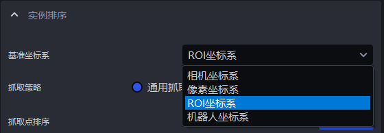
- Function description
Set a unified coordinate system for all instances to group and sort instances.
- Usage scenario
Common to depalletizing scenarios, random picking scenarios, and ordered loading/unloading scenarios
Strategies related to coordinates should first set the reference coordinate system
- Parameter description
| Parameter | Description | Illustration |
|---|---|---|
| Camera coordinate system | The coordinate system origin is above the object, and the positive Z-axis direction points downward; the XYZ values are the values of the center point of the object in this coordinate system | 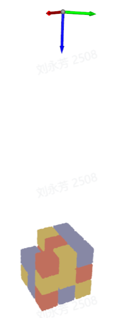 |
| ROI coordinate system | The coordinate system origin is approximately at the center of the pallet stack, and the positive Z-axis direction points upward; the XYZ values are the values of the center point of the object in this coordinate system | 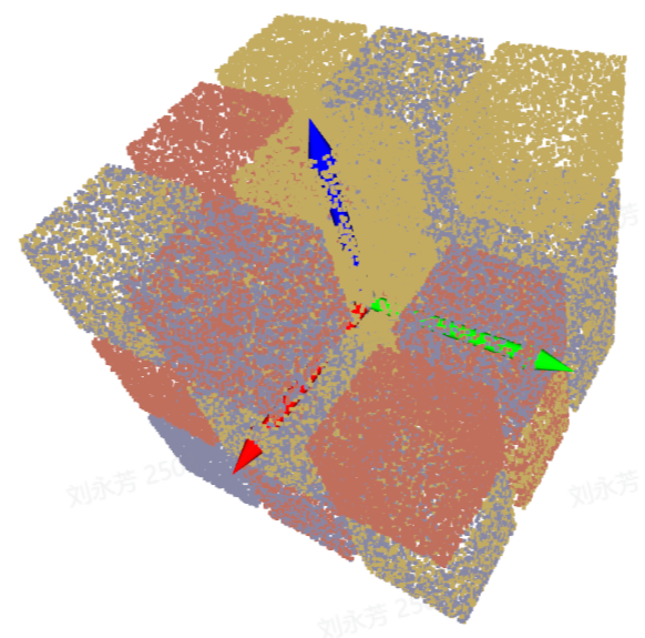 |
| Robot arm coordinate system | The coordinate system origin is on the robot arm itself, and the positive Z-axis direction generally points upward; the XYZ values are the values of the center point of the object in this coordinate system | 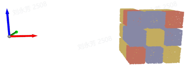 |
| Pixel coordinate system | The coordinate system origin is at the top-left vertex of the RGB image and is a 2D planar coordinate system; the X and Y values are the x value of the bbox detection box and the y value of the bbox detection box, and Z is 0 | 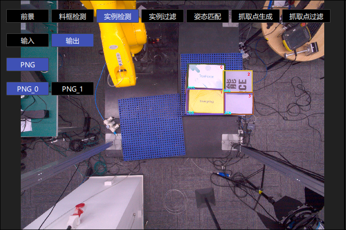 |
3.3.2 Picking strategy
- Parameter description
| Parameter | Description |
|---|---|
| Strategy | Select which value is used for grouping and sorting and how to sort it, including Pick Point center X/Y/Z coordinate values from large to small/from small to large (mm), from the middle to the sides / from the sides to the middle along the Pick Point XY coordinate axis (mm). Multiple items can be superimposed and executed in order. |
| Grouping step size | According to the selected strategy, divide Pick Points into several groups based on the step size. The grouping step size is the interval between two groups of Pick Points |
| Number of leading groups to keep | After grouping and sorting, how many groups of instances need to be retained |
| Strategy name* | Description | Grouping step size | Number of leading groups to keep | |
|---|---|---|---|---|
| Default | Range | Default | ||
| Pick Point center X/Y/Z coordinate values from large to small / from small to large (mm) | Use the X/Y/Z coordinate values of the Pick Point center for grouping and sorting | 200.000 | [0, 10000000] | 10000 |
| From the middle to the sides / from the sides to the middle along the Pick Point XY coordinate axis (mm) | Use the X/Y coordinate values of the Pick Point center and perform grouping and sorting in the direction of "middle to sides" or "sides to middle" | 200.000 | [0, 10000000] | 10000 |
3.3.3 Carton combination strategy
To solve the problems of low efficiency and limited applicable scenarios in traditional single-pick depalletizing, PickWiz adds a carton combination strategy in depalletizing scenarios to support picking multiple Target Objects in a single operation. It supports the core scenarios of "cartons with consistent dimensions" and "rectangular suction cups", covering more real project scenarios.
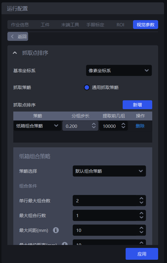
3.3.3.1 Multi-pick runtime configuration
(1)In sack single depalletizing or carton single depalletizing scenarios, enable Vision computation configuration - Vision computation acceleration.
(2)Under the Pick Point sorting module, select the carton combination strategy;
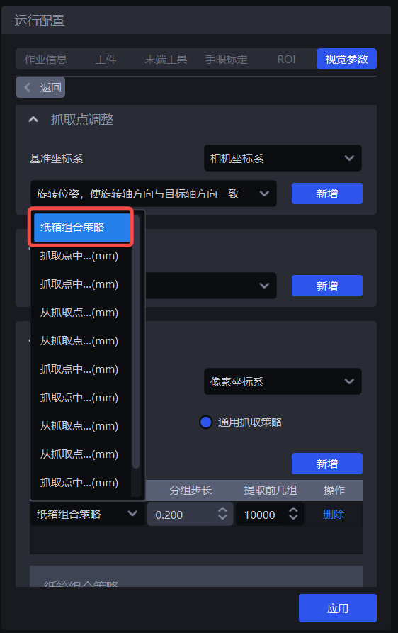
(3)Strategy selection: available options are the default combination strategy or combination along a specified carton pose axis. These are two methods for finding the largest number of cartons that can be combined.
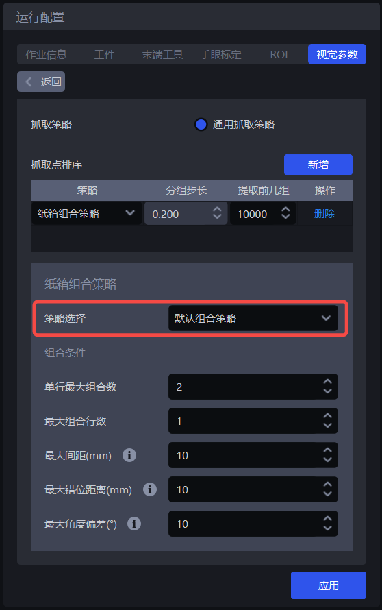
Default combination strategy: Find the largest number of cartons that can be combined along the X-axis and Y-axis directions of a carton Picking Pose.
Combine along a certain carton pose axis: Find the largest number of cartons that can be combined along the X-axis or Y-axis direction of a carton Picking Pose. This is suitable for scenarios where cartons are arranged in a straight line. When using this strategy, you need to choose the carton combination direction, namely the Picking Pose X-axis or the Picking Pose Y-axis.
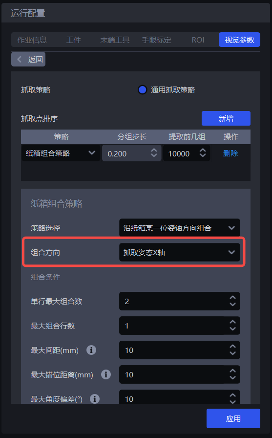
Note:
The combination direction is related to the positive and negative axis directions. Cartons can be combined only when they are on the same axis and in the same direction, and after combination, the orientation of the whole stack of cartons remains consistent with the orientation of a single carton before combination. Therefore, before combining cartons, make sure all cartons to be combined are placed in the same orientation, and unify the coordinates of the cartons to be combined to the same axis direction.
(4)Combination conditions: determine which cartons can be combined and how many can be combined at most.
Maximum cartons per row: the maximum number of cartons that can be combined in one row, default is 2.
Maximum number of combination rows: the maximum number of carton rows that can be combined, default is 1.
Maximum spacing (mm): cartons to be combined cannot be too far apart in the "combination direction", In the combination direction (axis direction), when the spacing between two adjacent cartons or cartons in different rows is less than this value, they can be combined into one group. The default is 10.
- Example: when searching for the maximum number of cartons along the Picking Pose X-axis, if the spacing between two adjacent cartons in the Picking Pose X-axis direction is 8 mm (≤10), they can be combined; if the spacing is 12 mm (>10), they cannot be combined.
Maximum misalignment distance (mm): cartons to be combined cannot be too far apart in the direction "perpendicular to the combination direction" . In the direction perpendicular to the combination direction (axis direction), when the misalignment distance between two adjacent cartons or cartons in different rows is less than this value, they can be combined into one group. The default is 10.
- Example: when searching for the maximum number of cartons along the Picking Pose X-axis, if two adjacent cartons are offset in the Picking Pose Y-axis direction by 8 mm (≤10), they can be combined; if they are offset by 15 mm (>10), they are no longer aligned and cannot be picked together.
Maximum angular deviation (°): cartons to be combined should face almost the same direction. In the combination direction (axis direction), when the rotational deviation angle of the cartons is less than this value, they can be combined into one group. The default is 10.
- Example: if a carton is rotated by 5° relative to the combination direction, as long as it does not exceed 10°, it can be combined; if it is rotated by 15° (>10), the orientation differs too much, the robot will be skewed when picking, and it cannot be combined.
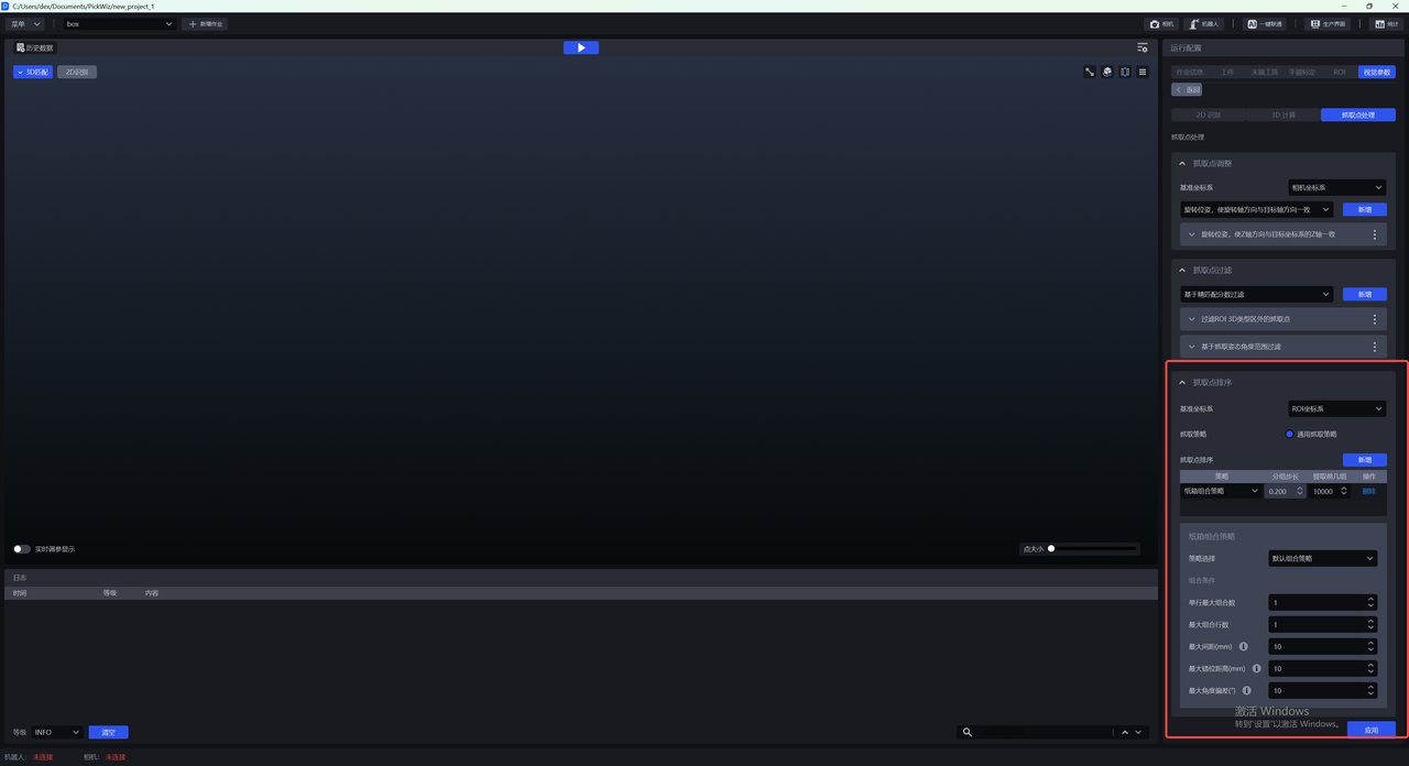
3.3.3.2 Robot configuration
(1)On the robot configuration page, add new placeholders in Vision computation communication message - Robot to PickWiz commands - Vision detection send command: maximum cartons per row and maximum number of combination rows, as shown below;
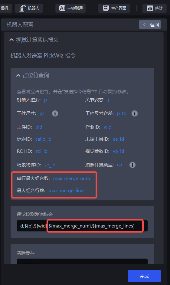
(2)In Vision computation communication message - PickWiz to robot commands - Pick-related information - Returned information when picking Target Objects, add Object Dimensions length, Object Dimensions width, and Target Object orientation.
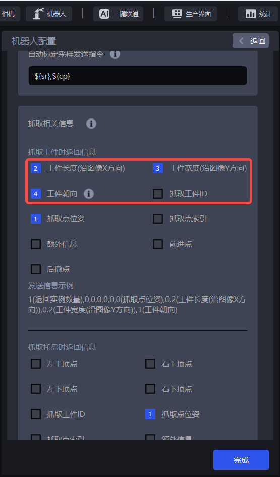
After the robot configuration is completed, click the Run button.
3.3.3.3 View multi-pick runtime results
(1)In the 3D Matching window, hover the mouse over an instance to view the combined picking information of a single instance after carton combination, including 2D recognition results, Picking Pose, and instance combination information.
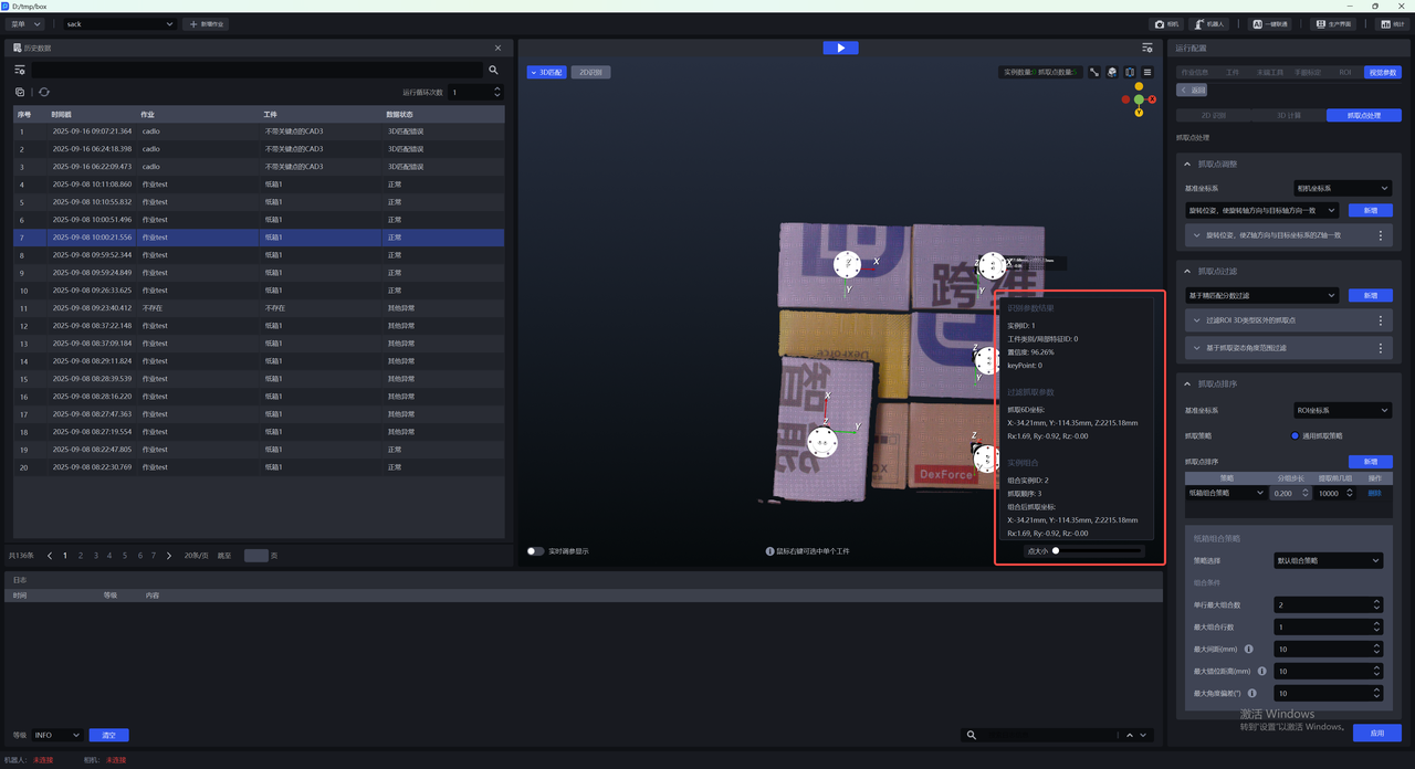
In the visualization window, click the Settings button in the upper right corner to set how the combined instance information is displayed.
Right-click an instance to view the combined picking information and Target Object information of the single instance.
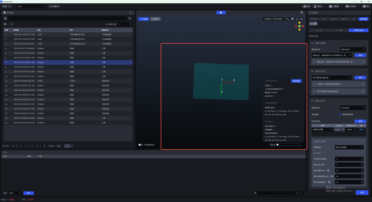
(2)In the 2D recognition window, you can use the relevant combination buttons in the menu bar to view the combined ID, combined Mask, and combined bounding box.