SPARROW Series Camera User Manual
1. Product introduction
SPARROWCamera is a structured light 3DCamera based on DLP projection. The core components use TI DLP2010 projection chip and Sony IMX392 imaging chip, and the lower computer has no computing unit. Data transmission uses GigE interface and supports multiple exposure modes. It is suitable for 3D scanning and industrial 3D defect detection. It can be used with industrial robots in industrial disordered grabbing, loading and unloading, etc. Scene.
2. Safety instructions
Please read the safety instructions carefully and operate in strict accordance with the following specifications. Otherwise, the Camera will be seriously damaged. Dexforce is not responsible for the resulting maintenance problems.
Blisters are strictly prohibited
Burning is strictly prohibited
Disassembly is strictly prohibited
It is strictly prohibited to connect the power supply privately
It is strictly prohibited to extend the network cable without permission
It is strictly prohibited to use the Camera in humid, condensation or dusty environments.
It is strictly prohibited to use the Camera in environments with strong magnetic fields and high-voltage discharge equipment (such as electric welding machines).
It is strictly prohibited to hit or beat with external force. If this happens, please contact the staff for maintenance.
Stay away from laser marking machines, laser engraving machines and other equipment that may cause damage to the Camera. If you must use it, please contact company personnel for confirmation.
It is strictly prohibited to use it beyond the distance. Use distance: XEMA-P: 100-150mm; XEMA-DCW: 0.3-0.5m; A-LCW: 1-2.5m; SPARROW: 0.3-0.5m; FINCH:
Use the Camera strictly in accordance with the product specifications and within the allowable high and low temperature range.
3. Specification Parameter
| Parameter | Model | SPARROW-D-1001 | SPARROW-SC-1100 |
|---|---|---|---|
| Hardware Parameter | Field of view (H/V) | 33°/23° | 34°/22° |
| Dimensions (mm) | 130*90*×37 | 226*90*38 | |
| Weight (kg) | 0.5 | 0.7 | |
| Baseline length (mm) | 75 | 170 | |
| resolution | 1440*1080 | 1440*1080 | |
| Interface type | Gigabit Ethernet | Gigabit Ethernet | |
| computing unit | / | / | |
| rated voltage | DC 12V ≥6.3A | DC 12V ≥6.3A | |
| Technology Parameter | Near-end site (mm) | 181*122 | 207*193 |
| Remote site (mm) | 300*209 | 615*393 | |
| Recommended working distance (mm) | 300~500 | 500~1000 | |
| Z axis accuracy | 0.05mm@0.4m | 0.05mm@0.6m | |
| Z axis repetition accuracyσ(μm) | 18@0.3m-0.5m | / | |
| Pixel pitch | 0.13mm@0.3m 0.21mm@0.5m | 0.2mm@0.5m 0.4mm@1m | |
| Typical acquisition time | 0.4-1.0s | 0.4-1.0s | |
| output data | Point Cloud image, Depth image, grayscale image | Point Cloud image, Depth image, grayscale image (color image) | |
| operating system supports | Windows(CUDA>=11.0) | Windows(CUDA>=11.0) | |
| SDK Interface | C/C++/C#/Python | C/C++/C#/Python |
4. Installation and connection
4.1 Unpacking inspection
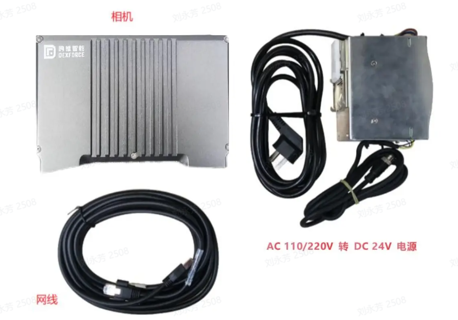
4.2 Hardware installation
There is only one installation method for the SPARROW series Camera. Connect the Camera network cable directly to the network port of the host computer. It cannot be connected through a router.
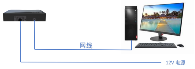
4.2 connection
Before connecting to the Camera, you should download and install the DexSense software. Please follow the [DexSense Installation Guide] (https://dexforce.feishu.cn/wiki/ETaWwwNyTiGSAYkw7gGcrI0tnkh?fromScene=spaceOverview) to download and install DexSense.
Since the SPARROW server runs on the host, the environment needs to be configured before it can use DexSense to connect to the Camera. The configuration is as follows:
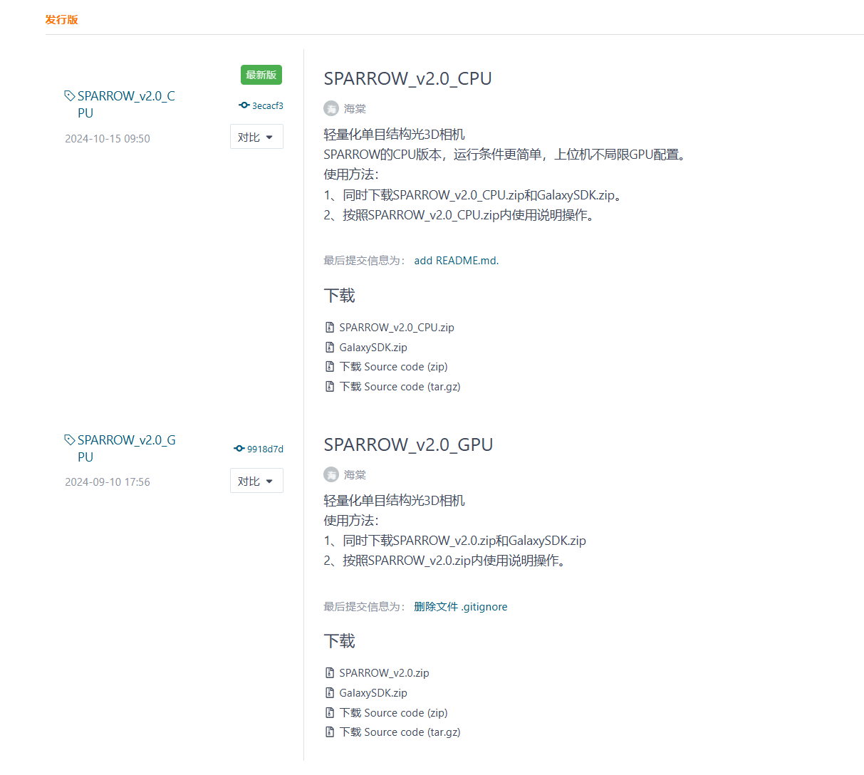
- When using it for the first time, download the server installation package SPARROW_V2.0_C(G)PU.zip和大恒安装包GalaxySDK.zip, address: https://gitee.com/open3dv/sparrow/releases (you can freely choose the CPU or GPU version to download according to the computer configuration)
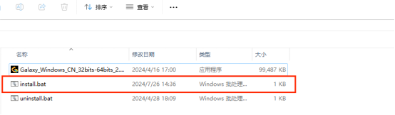
- Unzip the GalaxySDK compressed package in the release version and double-click to run install.bat. At this time, Daheng related libraries will be installed silently and wait for 2 minutes for the installation to complete.
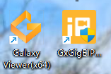
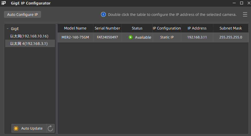
- At this time, there will be the installed GxGigE Daheng IP configuration tool on the desktop. Double-click to open it. If the IP is found with an exclamation mark, it means that the address is not in the same network segment. Just click the Auto Configure IP button. If it is normally available, there is no need to click Configure.
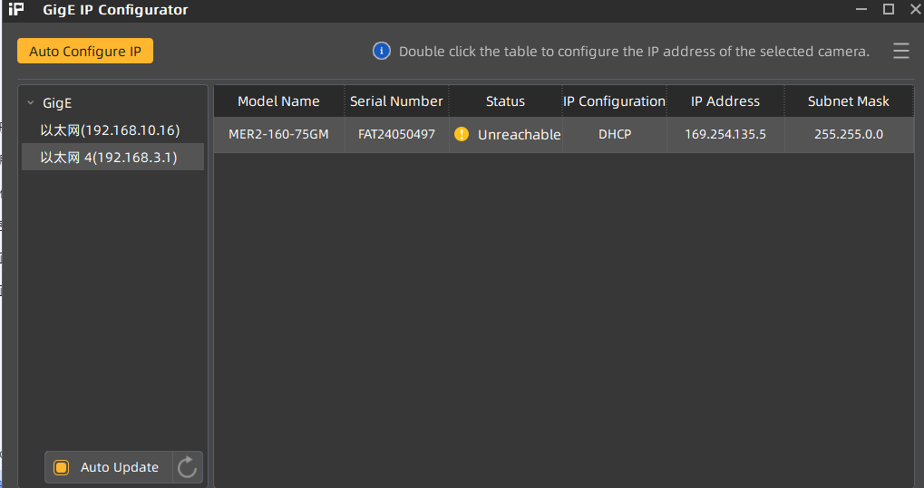
When Available is not an exclamation mark, it means you can start the SPOARROW server.
- Start the SPARROWCamera server
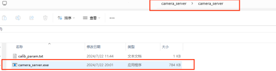
Enter the SPARROW_v2.0-camera_server_2.0--camera_server path and double-click to run the server program camera_server.exe.
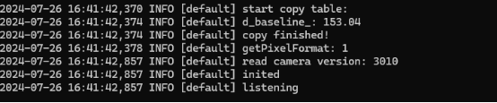
If you see the light machine emitting light and listening appears on the server, it means that the server is already running. The client can connect to the Camera normally.
Note: The server camera_server cannot be closed when in use, and when you want to close it, please press: Ctrl+C, otherwise the client will be illegally closed, and the Camera needs to be restarted before it can be used.
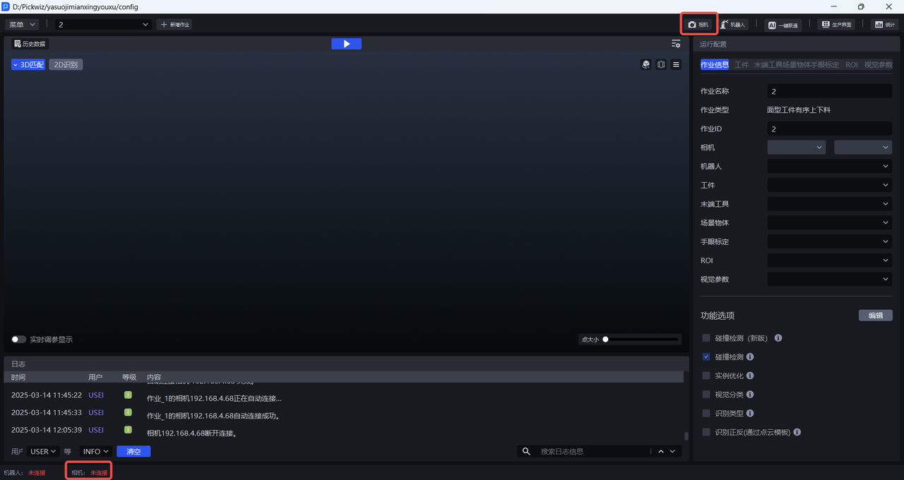
Open the DexSense software and search for the connection directly in the DexSense software interface
Use a network cable to connect the Camera and the industrial computer, turn on the Camera power, then click the
Camerapanel on the main interface to open theCamerainterface
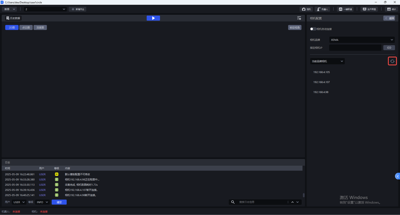
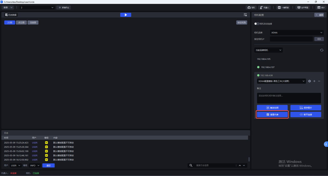
- On the Camera interface, select the Camera brand you want to connect to. You can choose from XEMA, FINCH, SPARROW, KINGFISHER, or KINGFISHER-R. Then click Search for the current brand Camera or a previously connected Camera to connect to the Camera with the corresponding IP address.
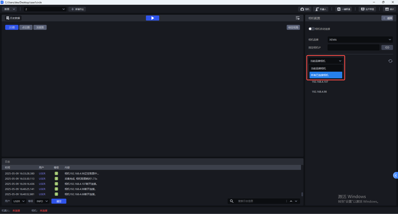
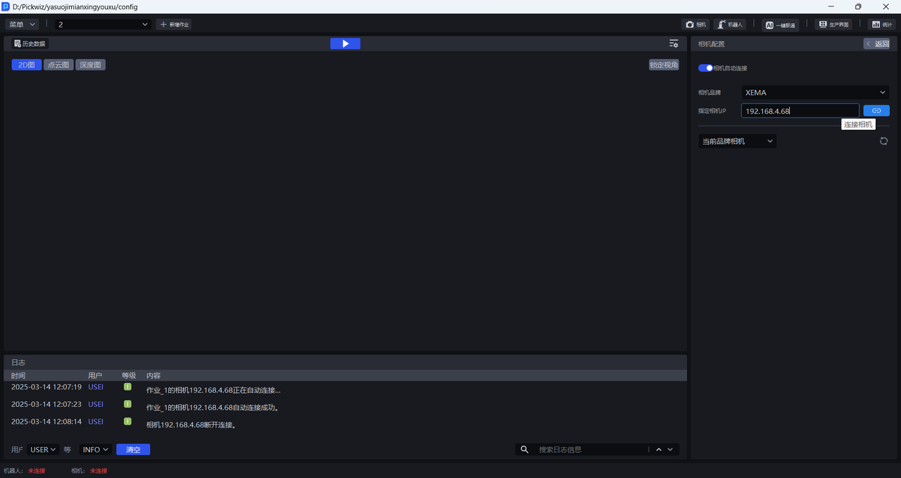
You can also directly enter the IP address of the Camera and click the Connect Camera button.
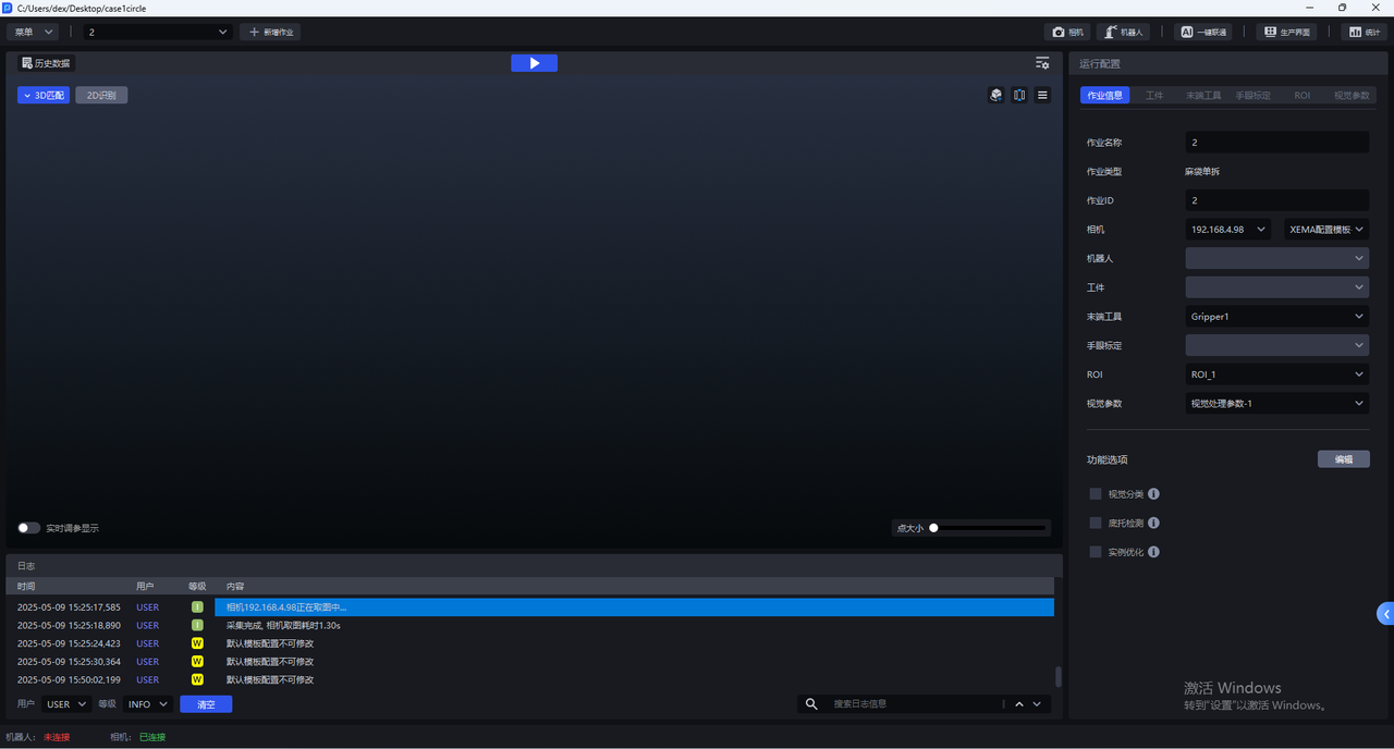
- After the Camera is successfully connected, you should select Camera for the current Task in the Task Information interface. After selecting Camera, the Camera connection status in the status bar changes to "Connected", as shown in the figure below.
5. Camera configuration
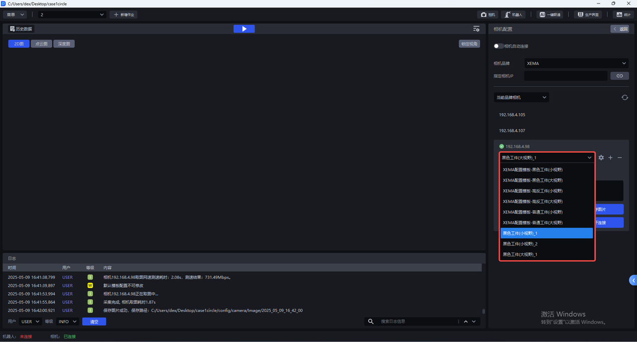
- Each Camera has multiple default configurations, and all default configurations cannot be changed. Select the corresponding default configuration, click "Trigger photo", use the imaging parameter to capture 2D images, Point Cloud images, and Depth images. You can check the imaging quality in the visualization window on the left.
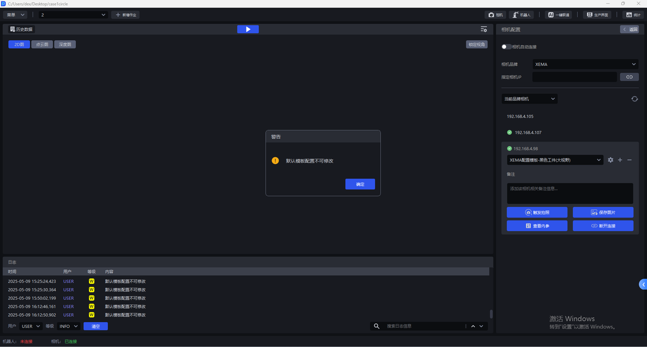

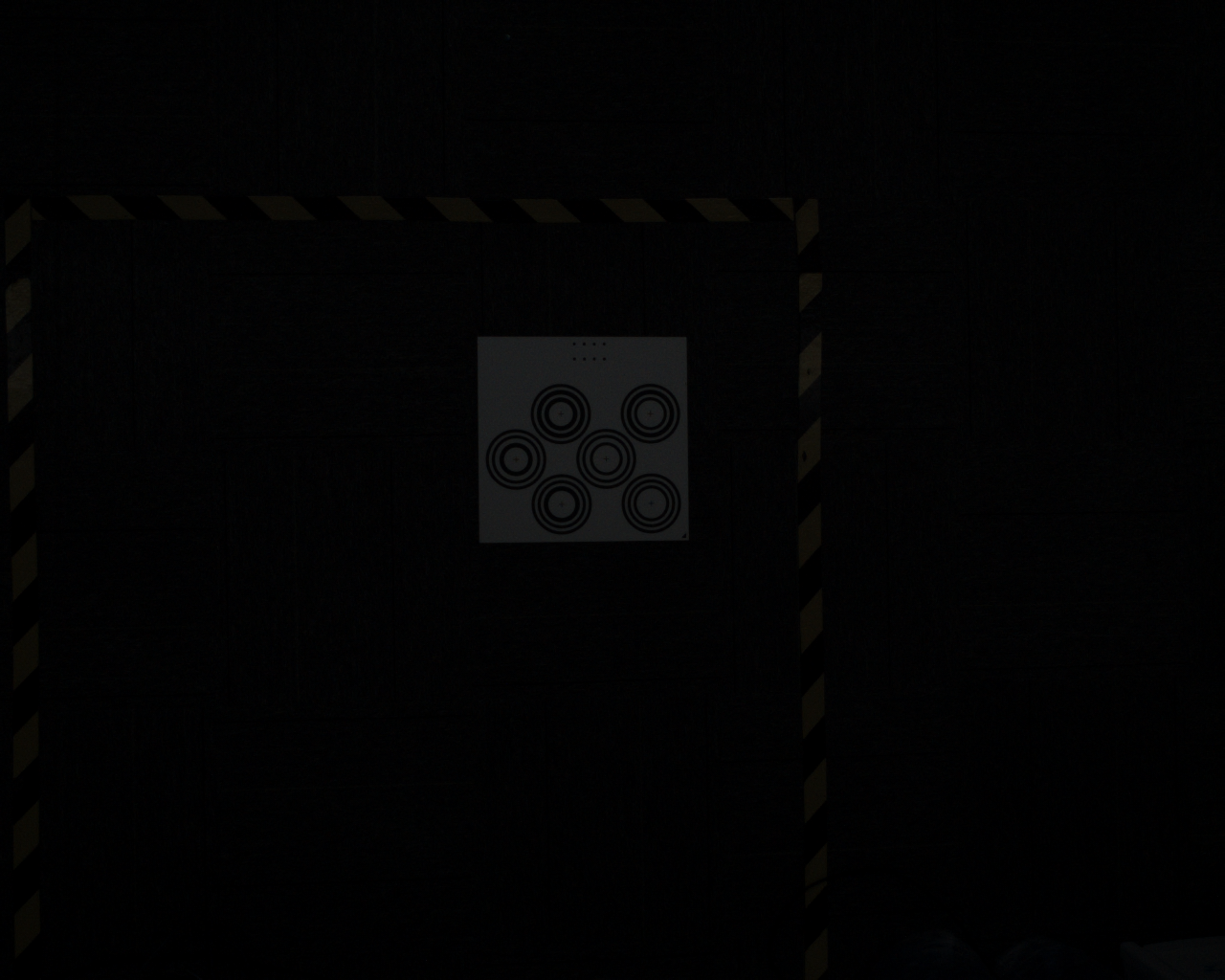
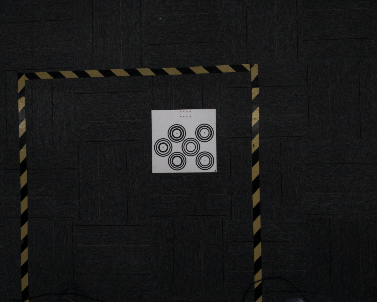
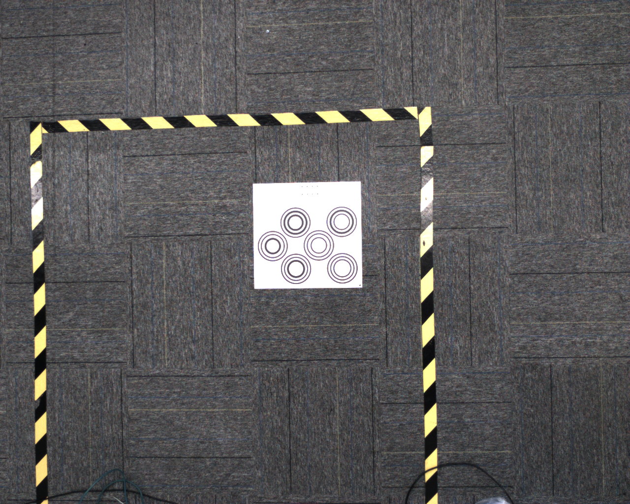
- The default camera configuration cannot be changed. If all 2D images taken with the default configuration cannot achieve normal exposure, you can click
+to copy the current Camera default configuration, add an identical Camera configuration, and directly enter the Camera configuration interface to modify Parameter.
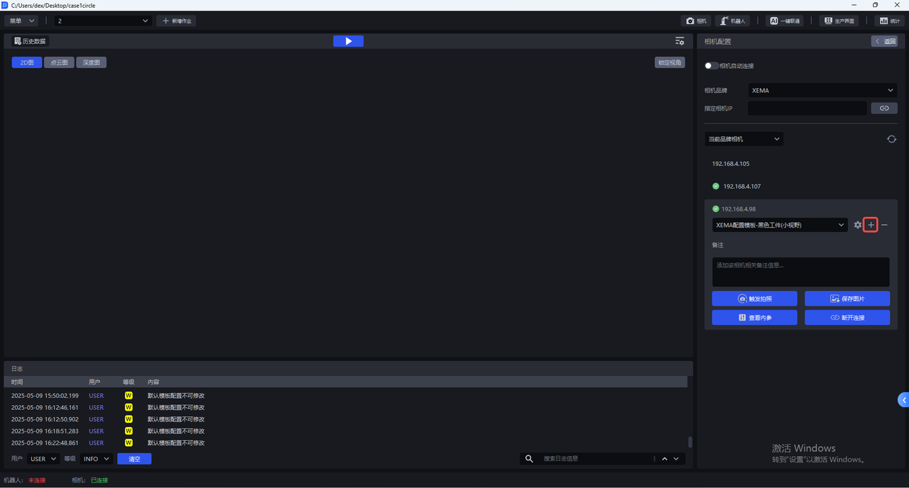
After copying the current Camera default configuration, you can switch to the new Camera configuration, click the Settings button , and enter the Camera configuration interface to modify Parameter.
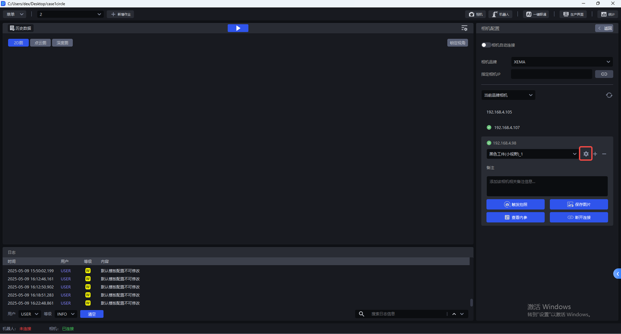
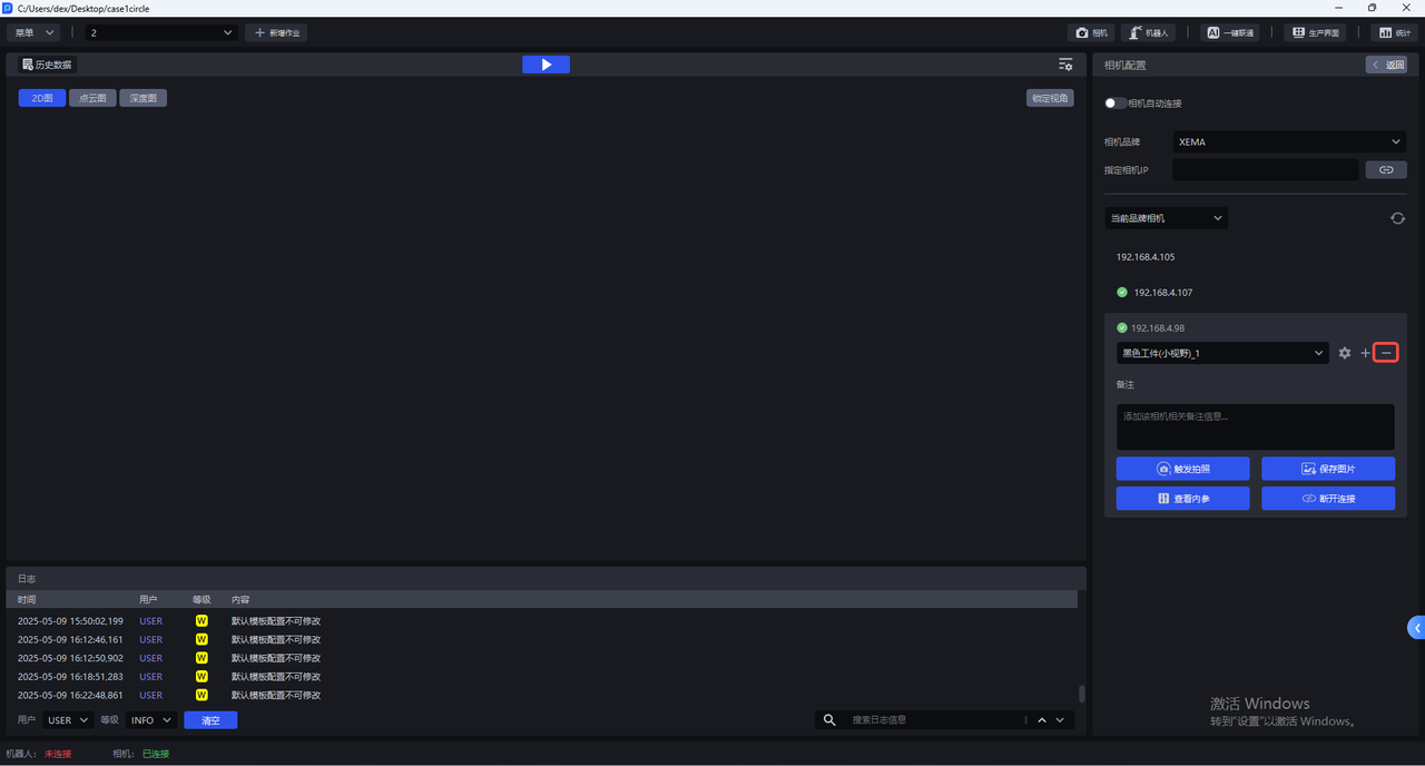
Click — to delete the newly added Camera configuration.
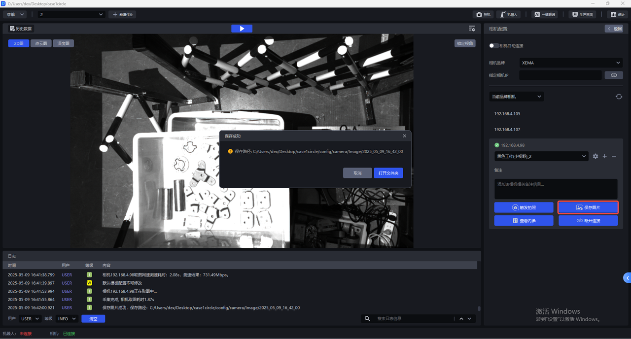
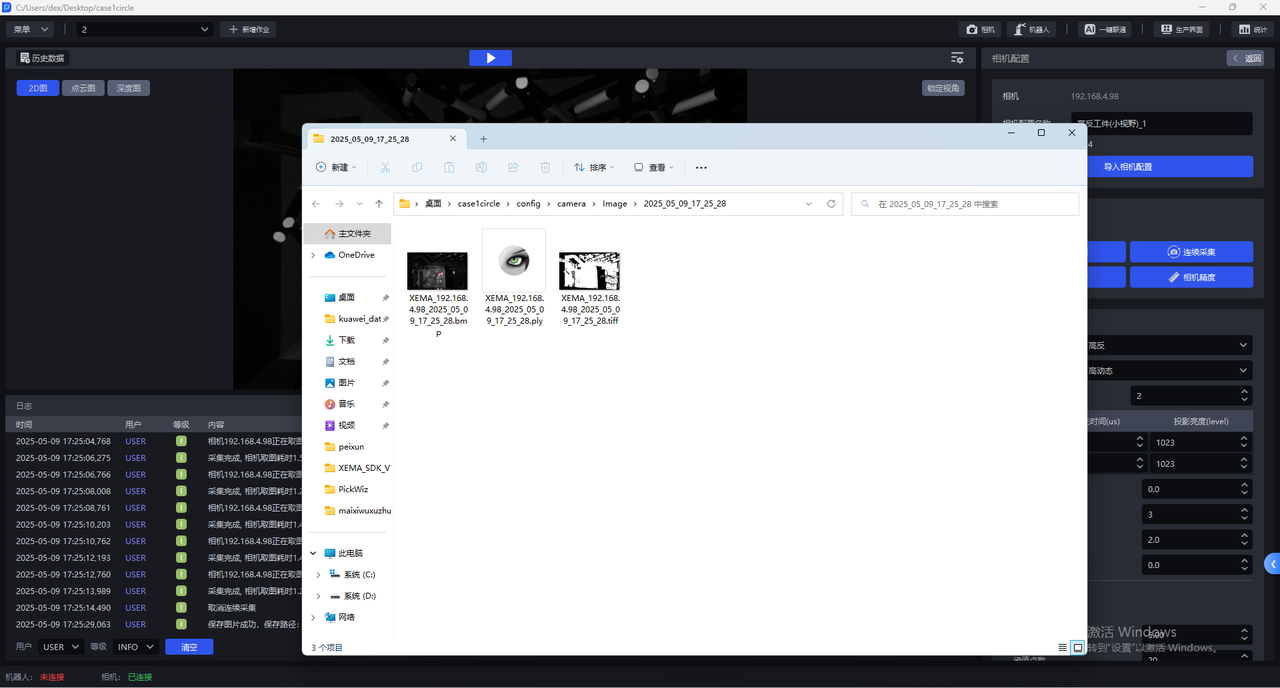
- Click
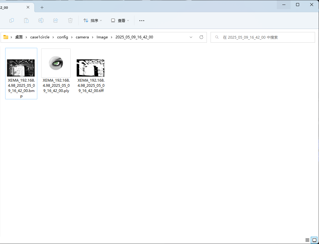
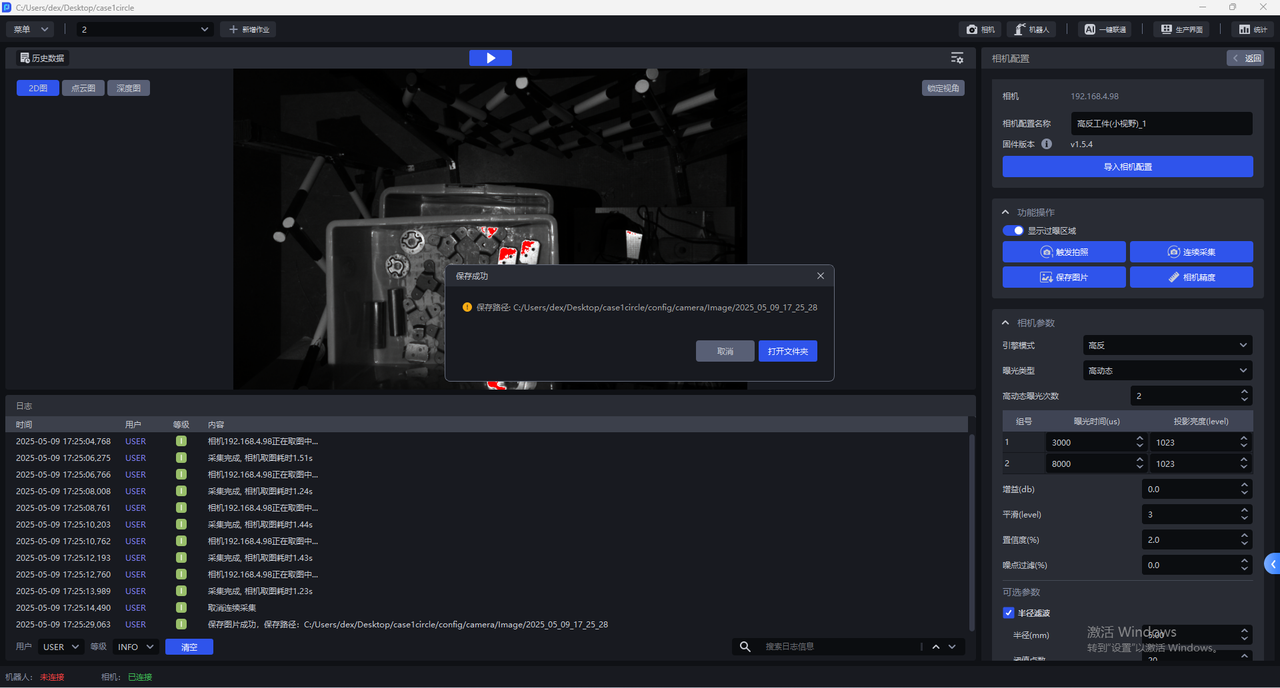
Save Imageto save the 2D image, Point Cloud image, and Depth image taken using the current configuration to the local machine, as shown in the figure below. The saving path is the project folder/config/camera/image/shooting time. The suffix is bmp for the 2D image, the suffix for the ply is for the Point Cloud image, and the suffix for the tiff is for the Depth image.
- Click
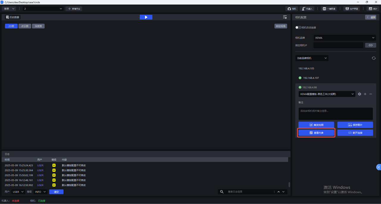
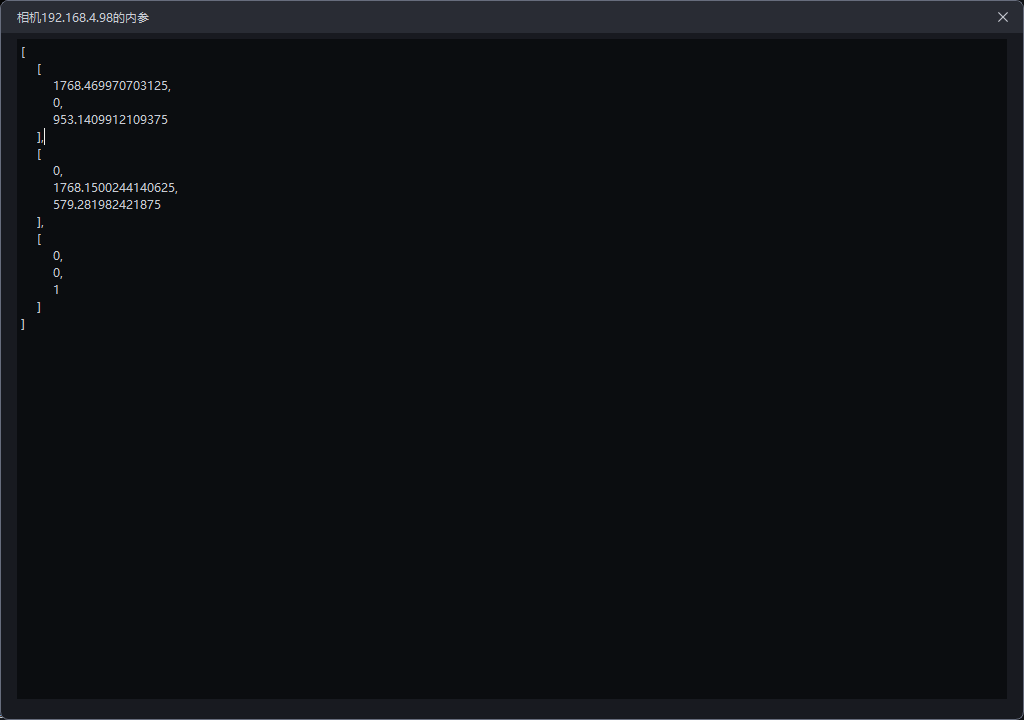
View Intrinsic Parameterto view CameraIntrinsic Parameter, including lens focal length, principal point coordinates, distortion coefficient, etc.
- Click
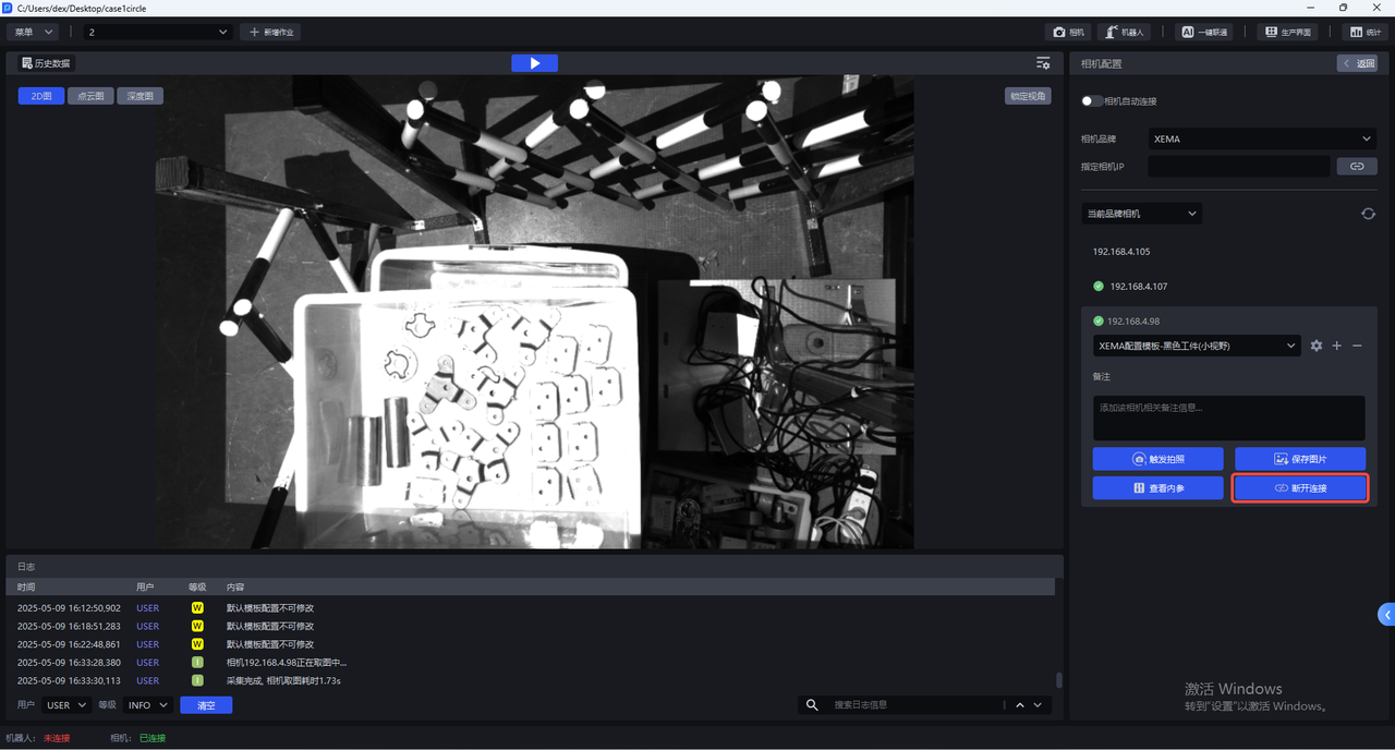
Disconnectto disconnect the Camera and re-select the Camera connection.
5.1 Import Camera configuration
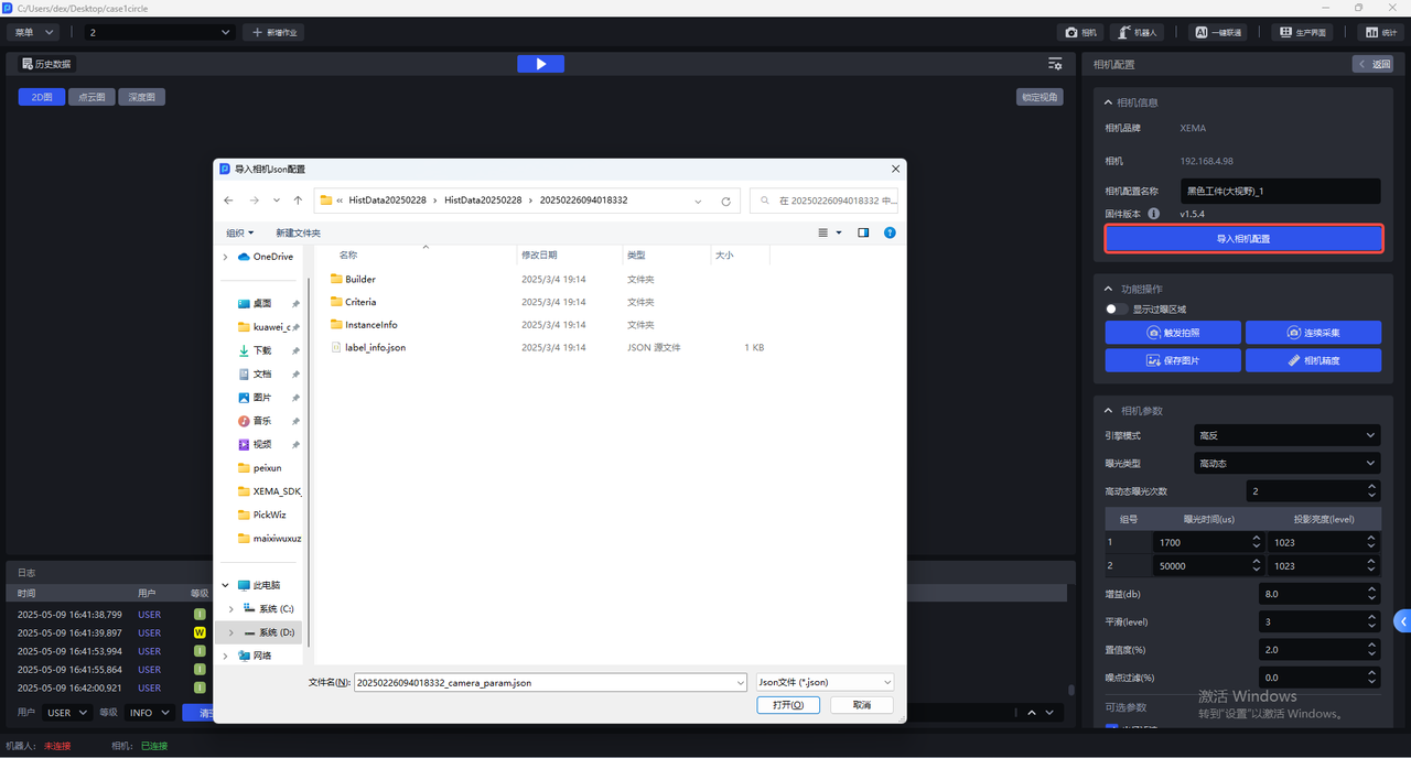
Enter the Camera configuration interface and click Import Camera Configuration to import the existing Camera configuration into the Camera.
5.2 function operation
The Camera configuration interface has the following functions:
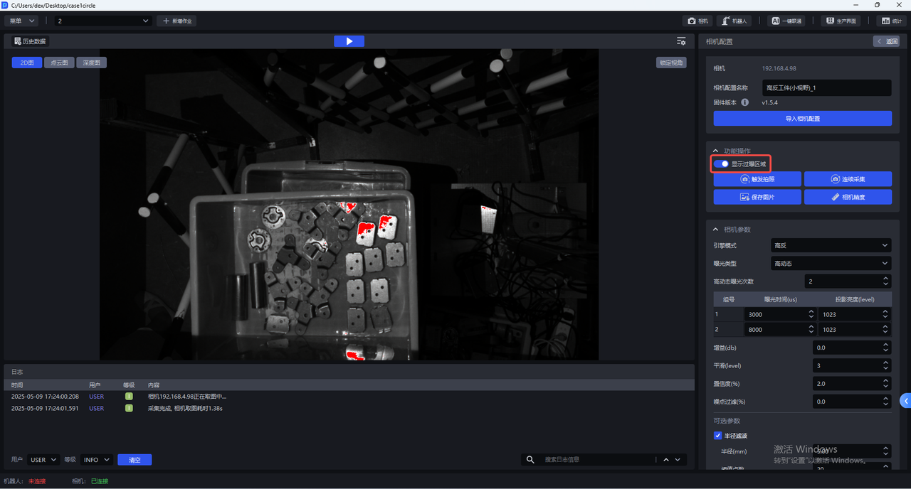
- Show overexposed areas
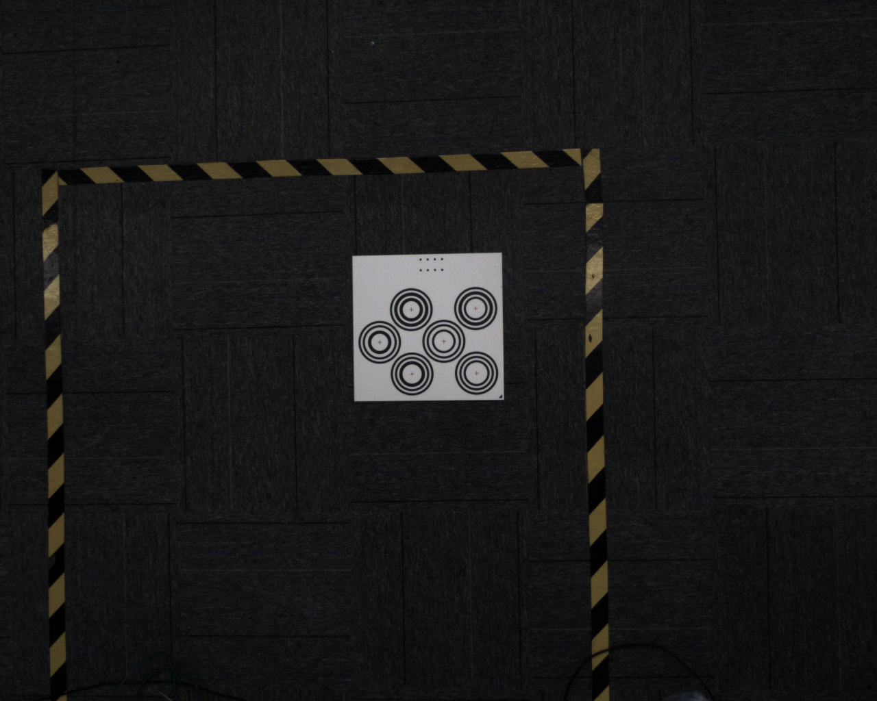
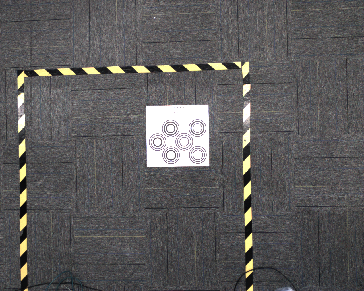
After turning on Show overexposure area, the visualization window will display the overexposure area of the current image, as shown in the figure below.
- Trigger photo
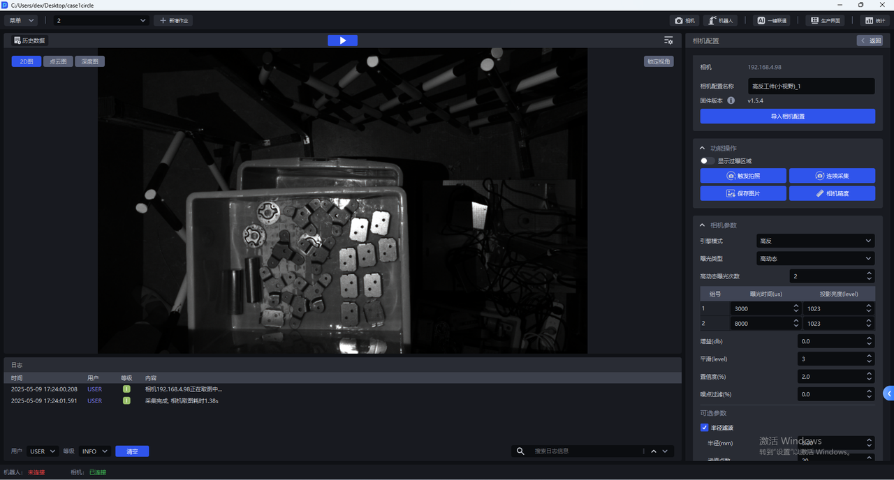
Click Trigger Photography to shoot 2D images, Point Cloud images, and Depth images using the current Camera configuration. You can check the imaging quality of the current Camera configuration in the visualization window.
- Continuous collection
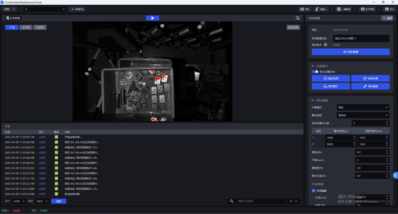
Click Continuous Acquisition and the Camera will take pictures continuously. Click Cancel Acquisition to stop taking pictures.
- save image
Click Save Image to save the captured 2D image, Point Cloud image, and Depth image
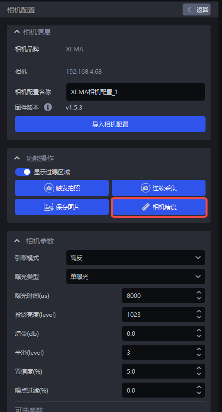
- Camera accuracy
Click Camera Accuracy to view and verify Camera accuracy
5.3 Camera accuracy
5.3.1 View Camera accuracy
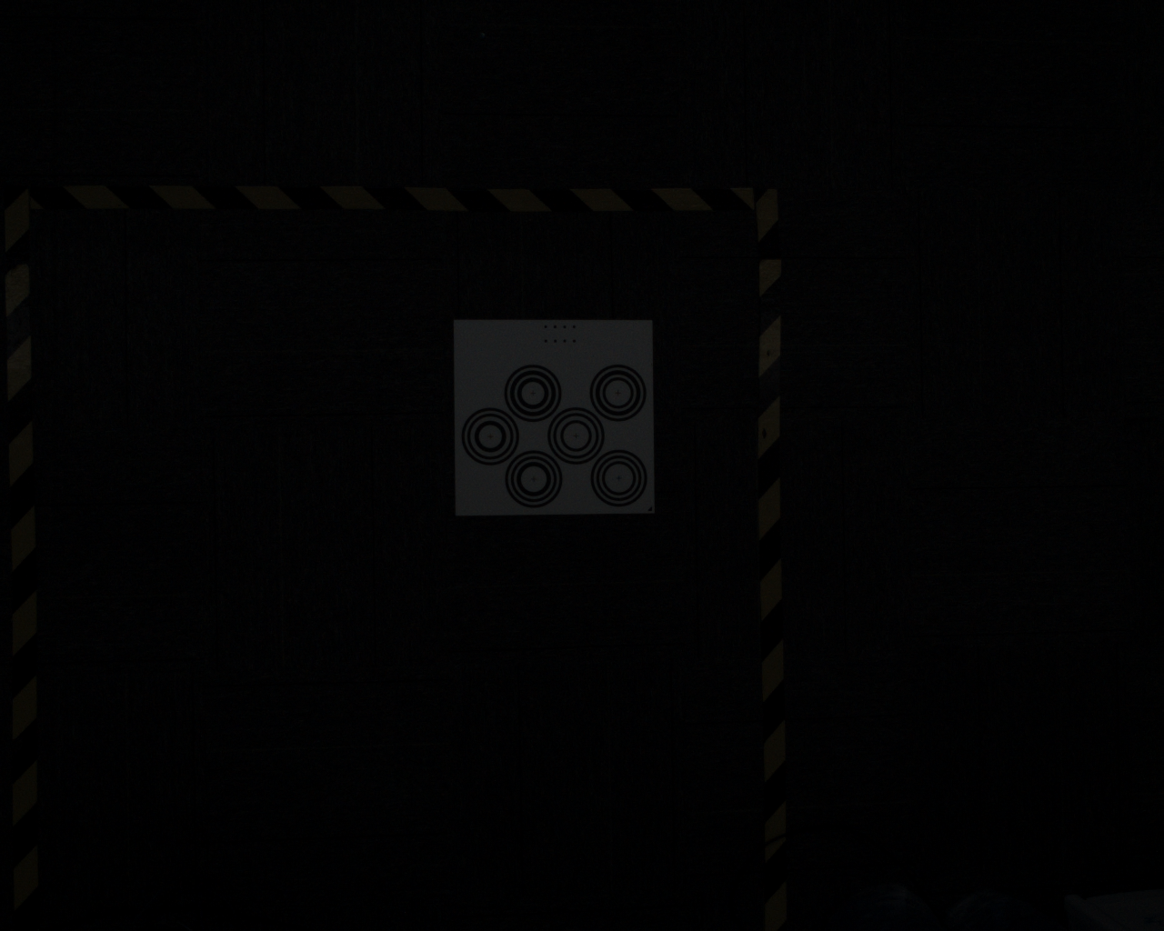
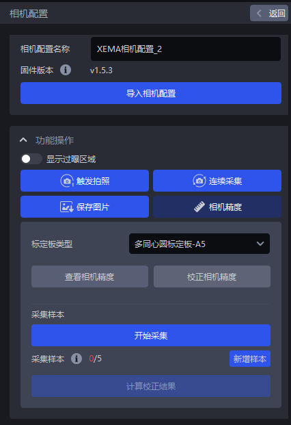
- Place the Calibration Board within the Camera's field of view, click
Camera Accuracyin the Camera configuration interface, and the Camera Accuracy interface will appear, as shown in the figure below
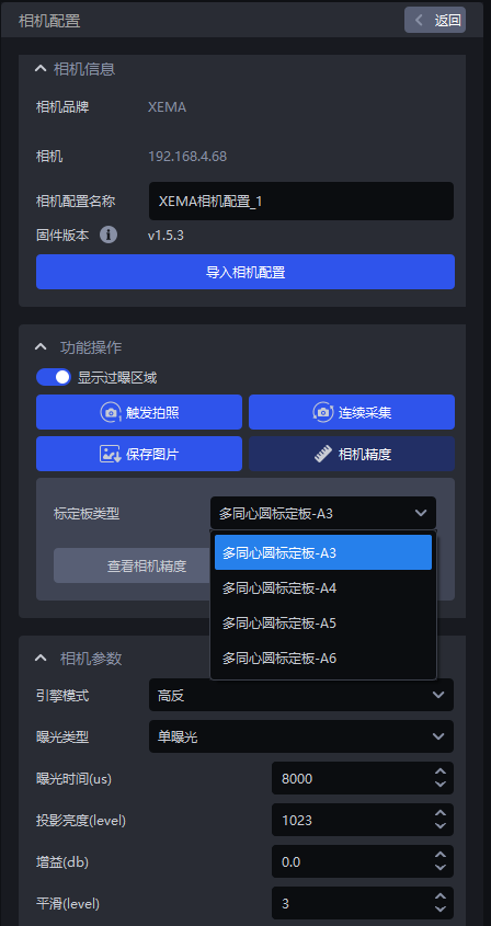
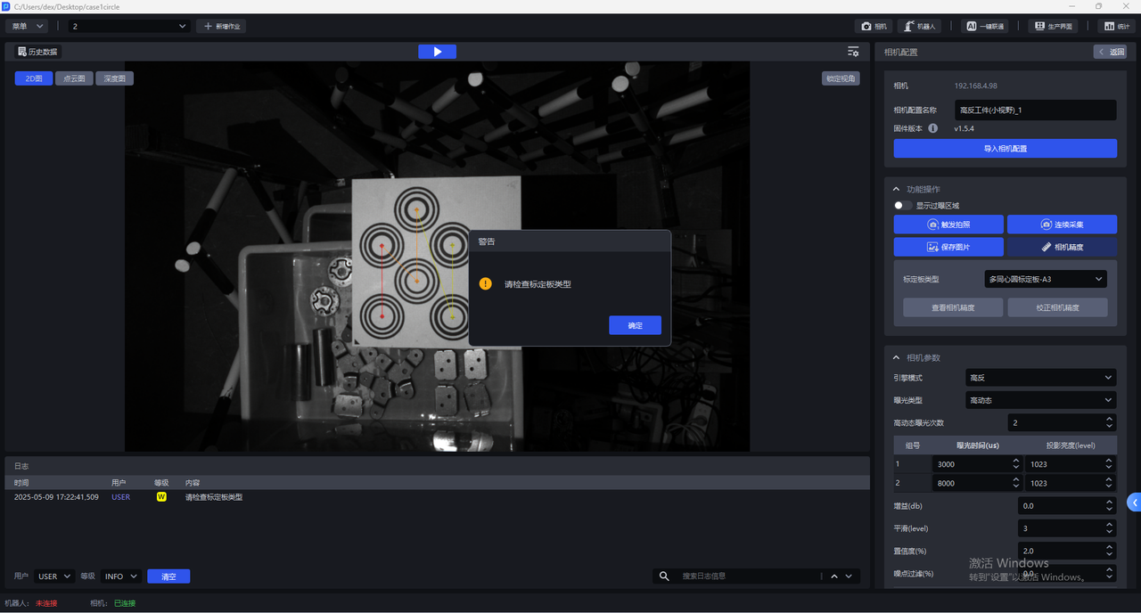
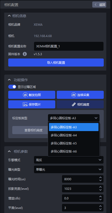
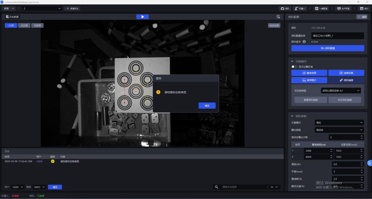
- Select the corresponding Calibration Board. If the selected Calibration Board does not match the actual one, a pop-up warning "Please check the Calibration Board type" will pop up, as shown in the figure below. If the Calibration Board type is A3, a pop-up warning will pop up.
- After selecting the correct Calibration Board type, click
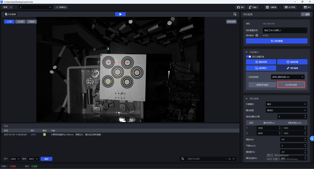
View Camera Accuracy, and PickWiz will automatically calculate the Camera accuracy of the current Camera. If the Camera accuracy meets the requirements, directly adjust the Camera imaging Parameter; if the Camera accuracy is too large, a prompt box will pop up saying "The error is too large, it is recommended to correct the Camera accuracy."
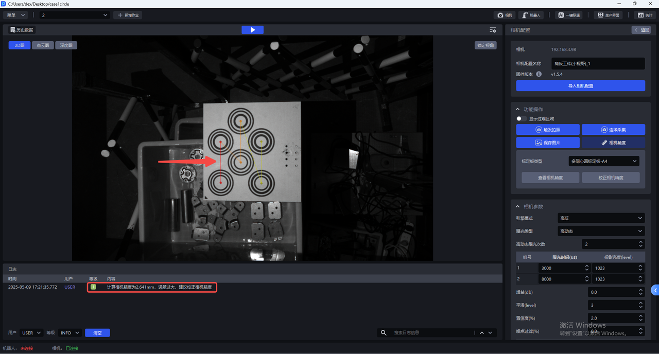
The camera accuracy of SPARROW series Camera is <0.2mm, which means the accuracy meets the requirements.
5.3.2 Calibrate Camera accuracy
During the actual use of the Camera and after the Extrinsic Parameter is corrected, it is necessary to verify whether the accuracy of the current Camera meets the requirements.
Check the Camera accuracy. If the Camera accuracy error is abnormal, the Camera accuracy should be corrected;
The current Point Cloud captured by the Camera fluctuates greatly, and the Camera accuracy should be corrected.
Before correcting the camera accuracy, you should turn on `Show overexposure area' to check the exposure level of the Camera imaging. If there is an overexposed area, adjust the exposure time of the single exposure to ensure that the Camera imaging exposure is normal.
After the correction is completed, the Camera imaging Parameter should be switched back to its original configuration.
- Click
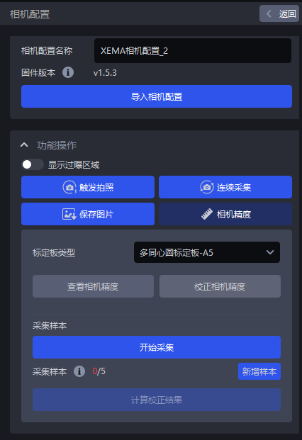
Camera Precisionin the Camera configuration interface
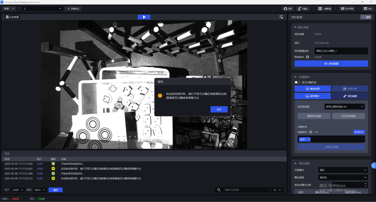
- Select the corresponding Calibration Board. If the selected Calibration Board does not match the actual one, a pop-up warning "Please check the Calibration Board type" will pop up, as shown in the figure below. If the Calibration Board type is A3, a pop-up warning will pop up.
- After selecting the correct Calibration Board type, click
Calibrate Camera Accuracy
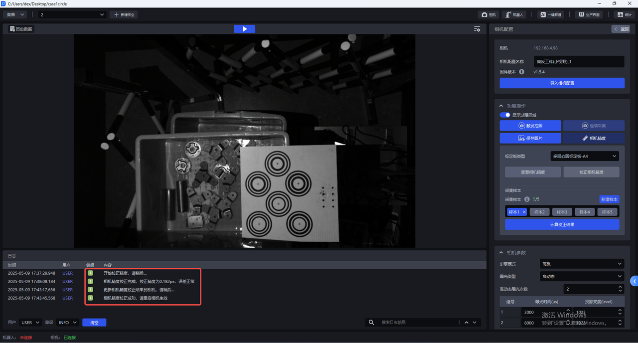
- Place the Calibration Board horizontally in the center of the Camera's field of view, click "Add Sample", and the Camera will start sampling and verifying the sample. If the collected sample passes the verification, it will be added under "Collect Sample", as shown in the figure below
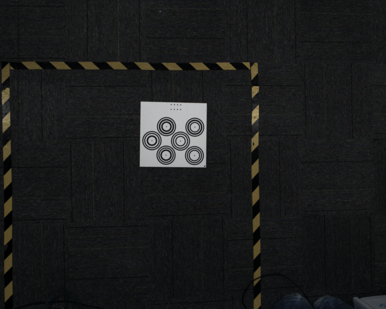
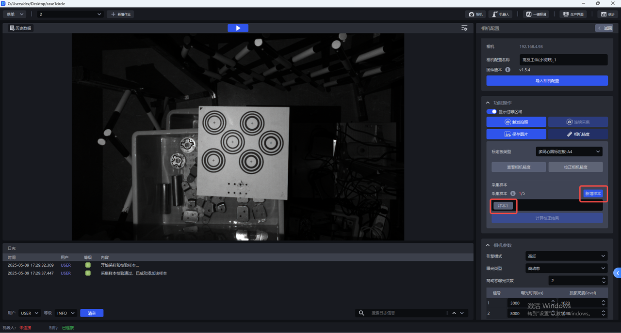
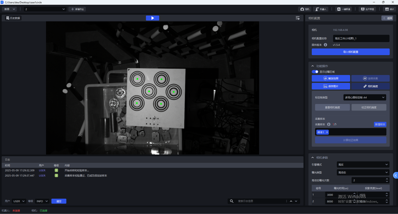
Click Sample x to view the collected samples. The centers of all concentric circles on the Calibration Board of samples that pass the verification turn green.
- Move the Calibration Board to the 4 corners within the Camera's field of view to add new samples
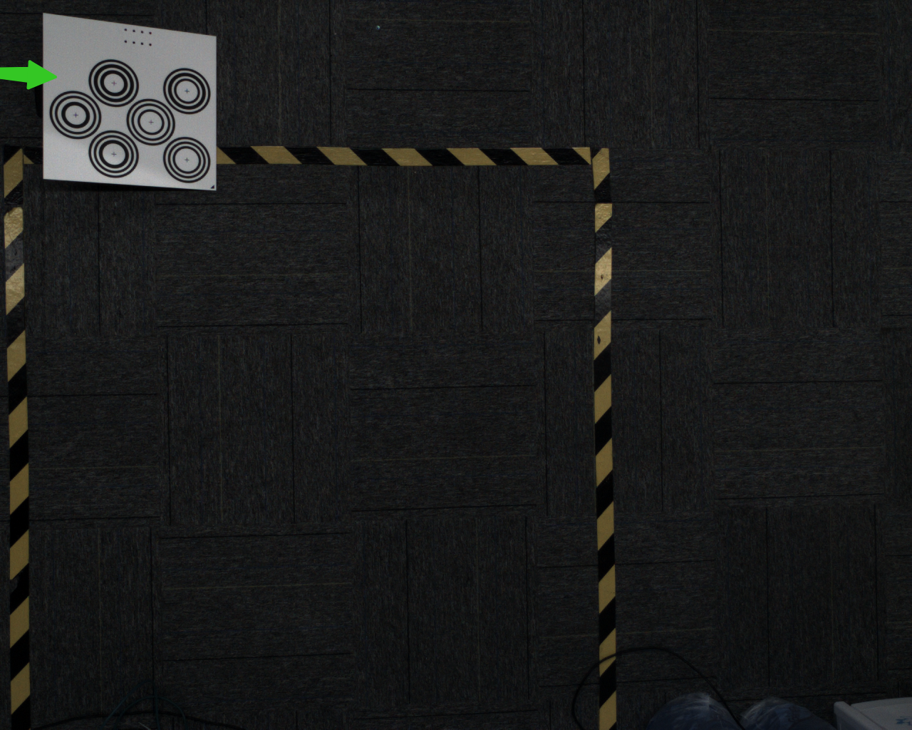
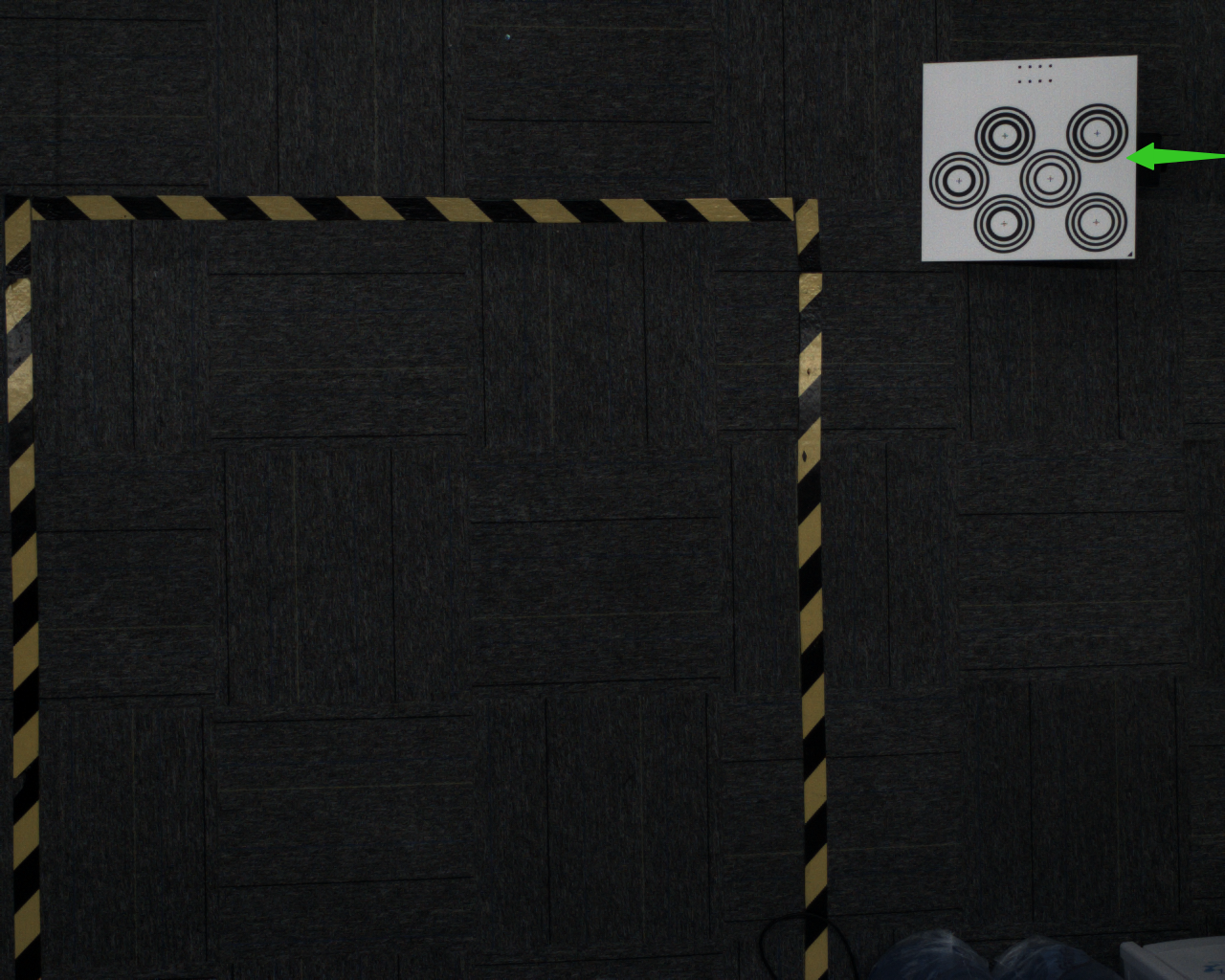
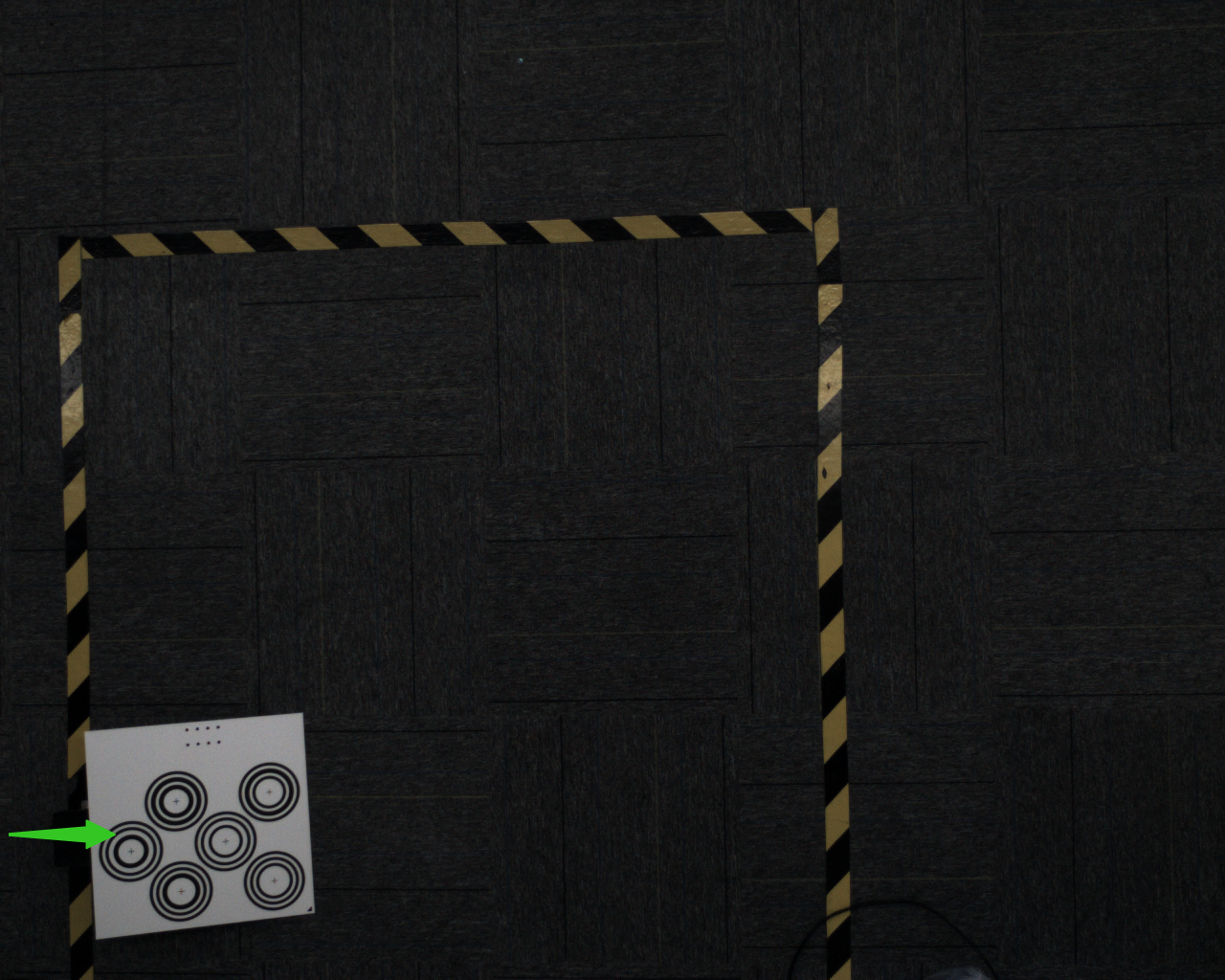
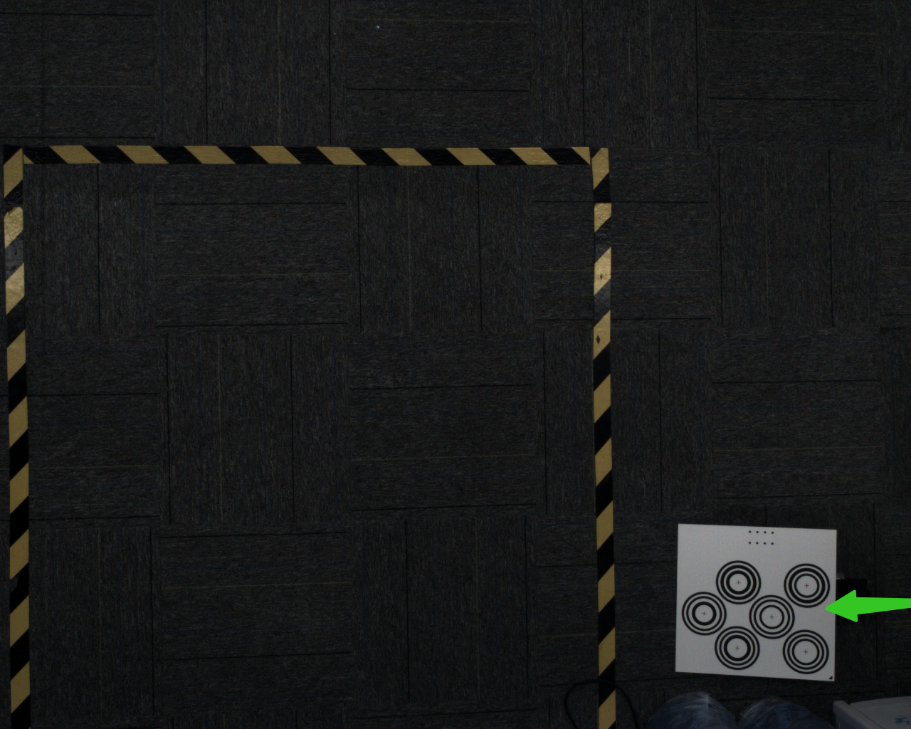
Place the Calibration Board at an angle at each corner. Place the Calibration Board at an angle of 15-30°. The tilt angle should not be too large or too small.
- After adding 5 samples, click
Calculate Correction Results
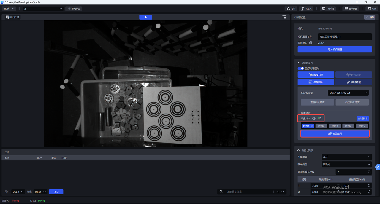
- After the correction is completed, a prompt box will pop up "Camera accuracy correction is completed. The correction accuracy is x and the error is normal. Do you want to overwrite the current CameraParameter configuration?"
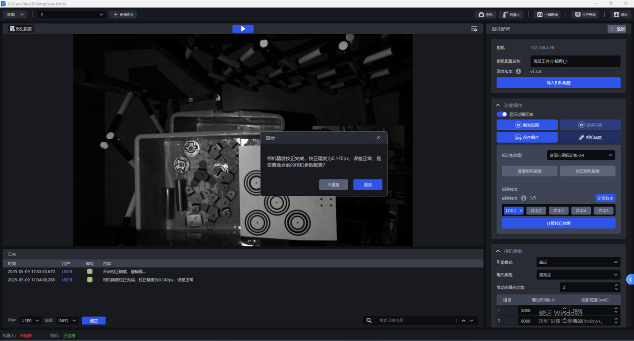
If you choose to overwrite the current CameraParameter configuration, the Camera accuracy correction results will be updated to the Camera, and you need to restart the Camera to take effect.
6. Camera parameter adjustment
6.1 Required Parameter
6.1.1 engine mode
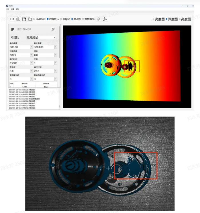
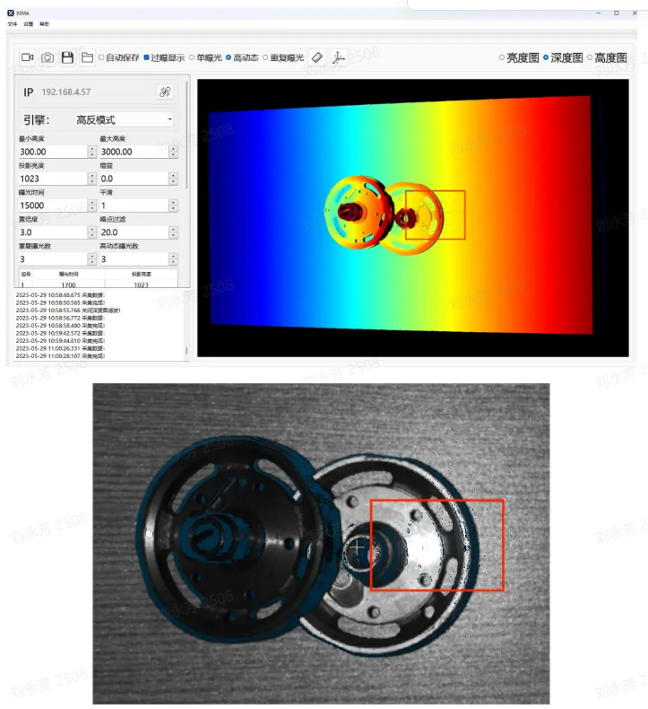
The engine modes include normal, high-reflective and black modes. The high-reflective mode is excellent for high-reflective parts, the black mode is excellent for black targets, and the normal mode can deal with ordinary targets.
| Engine Mode | Description |
|---|---|
| General | Applies to general Target |
| Highly reflective | Suitable for highly reflective Target |
| Black | Available for Black Target |
6.1.2 exposure type
(1) Single exposure
For ordinary texture Target, you can use single exposure
(2) High dynamics:
For highly reflective targets, you can use the HDR function for Point Cloud fusion.
Exposure type High Dynamics should be used in conjunction with Engine mode High Dynamics
High Dynamic Range Imaging (HDRI or HDR for short) is a set of technologies used to achieve a larger exposure dynamic range (that is, a greater difference between light and dark) than ordinary digital imaging technology.
High dynamic makes the image more distinct and the difference between light and dark obvious (especially when facing reflective targets).
Parameter adjustment suggestions:
- When using high dynamics, you can select the number of high dynamic exposures based on the specific Scene and Target. The value range is 2~6, and the default is 2. If the 3DPoint Cloud quality and 2D image quality are poor, the number of groups should be increased to expose the object multiple times to achieve the best imaging quality.
It is recommended to use fewer high dynamic exposures while meeting Point Cloud quality.
(3) Repeated exposure: The number of times the Camera needs to repeat shooting. The function is to improve the signal-to-noise ratio (the ratio of signal to noise). The higher the signal-to-noise ratio, the better. In this way, random noise will be suppressed and effective information will be increased. The value range is 0~10.
For black objects, you can use repeated exposure to optimize the Point Cloud through multiple exposures.
6.1.3 exposure time
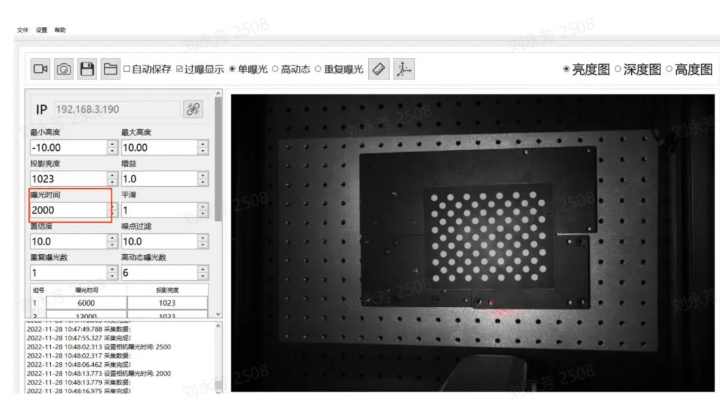
Camera exposure time: Exposure time is the time it takes for the reflected light from the scene to reach the imaging photosensitive material through the lens and the shutter to open. The longer the exposure time, the more light comes in. If the exposure time is too long, overexposure will occur, which will affect the Point Cloud. The size should be adjusted based on the actual situation.
Range: 1700-100000
Exposure time and projection brightness are one group, and the number of high dynamic exposures is one group. Set the appropriate exposure time and projection brightness value for each group.
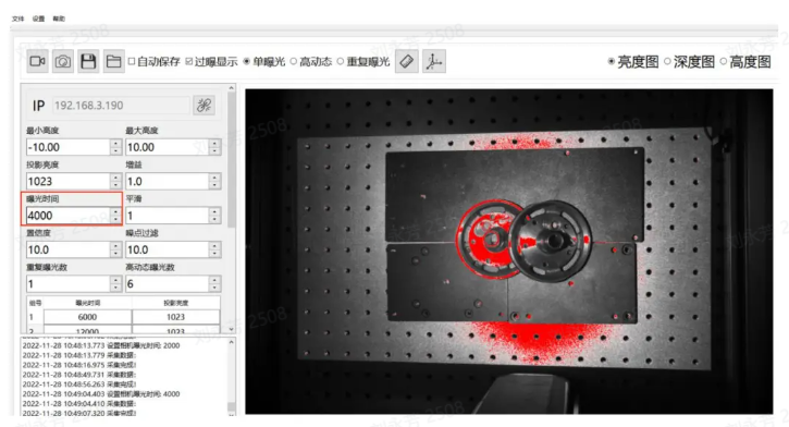
**Exposure time: **Exposure time is the time for light to enter the Camera when the Camera shutter is open. The longer the exposure time, the more light enters and the clearer the image.
If the exposure time is too long, overexposure will occur. You can turn on the display of the overexposure area. The red part is the overexposure area.
6.1.4 projection brightness
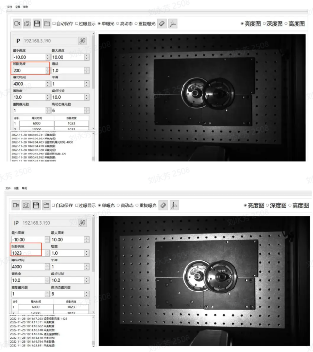
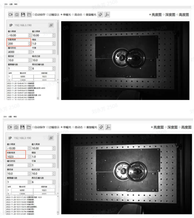
Projection brightness refers to the intensity of the projection light. The greater the light intensity, the brighter and clearer the image. Within a certain range, the human eye will feel that the image is clearer because of the high brightness. If it exceeds this limit, excessive brightness will make it impossible to see the image clearly.
Range: 0-1023
The larger the value, the brighter the projection, which can effectively improve the signal-to-noise ratio. It is recommended to use the maximum value. If the exposure time is still overexposed after adjusting it to the minimum, consider reducing the value.
Note: It is recommended to adjust the brightness to 1023
6.1.5 gain
Adjust the brightness of the picture.
Range: 0-24
The gain value of 2DCamera can be adjusted and should be increased appropriately. As the gain increases, the noise will increase accordingly.
6.1.6 smooth
Range:0-5
Smooth operations on Point Cloud
6.1.7 Confidence
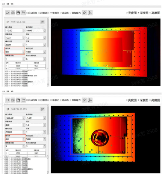
Confidence indicates the degree of trustworthiness. Point Cloud will be screened initially, usually 2-5, and customers can adjust it on site.
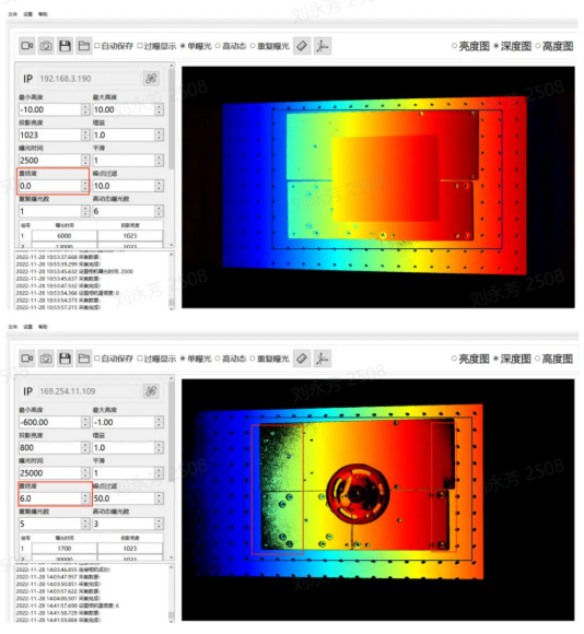
When Confidence is lowered, more of the black part in the Depth image is retained; conversely, when Confidence is raised, the black noise in the Depth image will be removed.
Range: 0-100
6.1.8 noise filter
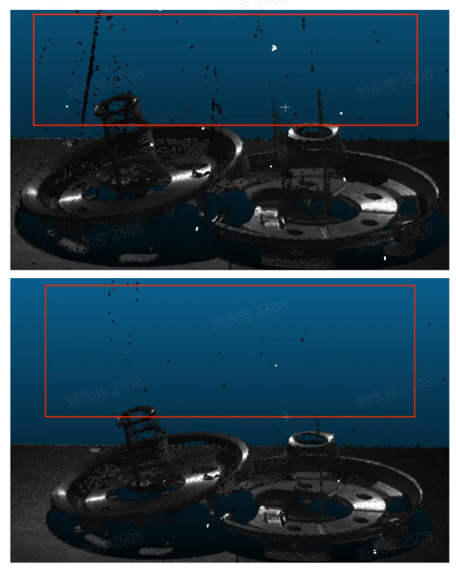
In the machine vision application scene, such as detecting metal, aluminum foil surfaces, reflective films, and smooth surface items, specular reflection will cause excessive local reflected light, thereby losing the original information of the object and interfering with machine vision detection. Noise filtering can partially eliminate the generated noise and preserve the original information of the object.
Range 0-100
When identifying items on metal, aluminum foil surfaces, reflective films, and smooth surfaces, specular reflection will cause excessive local reflected light, thereby losing the original information of the object and interfering with Pickwiz recognition and detection of images. Increasing the noise filter value can partially eliminate the generated noise and preserve the original information of the object.
6.2 Optional Parameter
6.2.1 radius filter
For each point in the Point Cloud, determine a sphere with a radius r and select the number of effective points. If the number of internal points is less than the effective points, it will be considered a noise point and will be eliminated. The smaller the radius and the larger the number of effective points, the more obvious the filtering effect will be.
Radius range: 0-99
Valid point range: 0-99
6.2.2 depth filter
For filtering suspended noise in the Z-axis direction, the larger the threshold, the more obvious the filtering effect. Based on the Depth image filtering method, the Threshold is recommended to be 33 at a distance of 1000mm.
Range: 0-100
6.2.3 reflection filter
Filter the facade noise caused by metal mutual reflection. The larger the threshold, the more obvious the filtering effect will be.
Range: 0-100
6.2.4 phase correction
Phase correction, namely Point Cloud grayscale compensation, is a method of correcting grayscale information in three-dimensional Point Cloud data. The purpose of Point Cloud grayscale compensation is to eliminate these grayscale value differences and convert the grayscale information in Point Cloud into a value corresponding to the reflectivity of the actual object surface. The larger the threshold, the more obvious the correction.
Range: 0-100
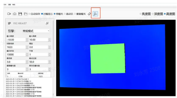
Instructions for use: First place the Calibration Board, using the plane of the Calibration Board as the reference plane. As shown in the picture above.
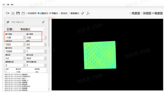
As introduced in the Maximum Height and Minimum Height section, adjust the maximum height to 1, adjust the minimum height to -1, and only display the Calibration Board part, as shown in the figure above.
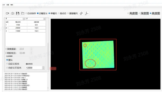
When phase correction is not turned on, the Calibration Board is as shown in the picture above. In the actual Calibration Board, the entire Calibration Board is flat, and there are no up and down fluctuations in the circular and non-circular parts. However, the actual photographed effect is that of a circle with undulations.
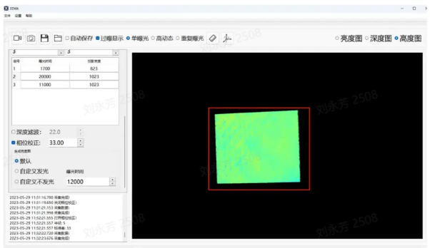
After turning on the phase correction, it is found that there is basically no color difference or the difference is not obvious on the Calibration Board, indicating that the correction is successful.
6.2.5 2D image overlay exposure
This function can separately cover the initial 2D image after obtaining the Point Cloud; sometimes the Point Cloud is good, but the 2D image is too dark and overexposure, which does not meet the requirements. At this time, the 2D overlay exposure can be turned on to cover the original 2D image.
If you choose Luminous, you can set the exposure time, gain, and shooting method (single exposure or high dynamic).
If you choose not to emit light, it depends on the light brightness in the environment. You can also set the exposure time, gain, and shooting method (single exposure or high dynamic) by yourself.
stack gain
When using the 2D stacked exposure function, you can adjust this gain to make the picture brighter.
Overlay exposure time
When using the 2D overlay exposure function, you can adjust this exposure time to make the picture brighter.