3D vision guidance kit hardware construction
The 3D visual guidance suite is a complete solution developed by Dexforce that includes hardware (Camera, industrial computer), software (3D visual guidance software), and AI algorithms. It is used to solve various typical scenes of 3D visual guidance. This article will introduce the installation method and connection method of hardware (Camera, Robot, industrial computer).
1. Hardware introduction
The hardware of the 3D vision guidance kit mainly includes Robot, Camera, and industrial computer, as shown in the following figure:
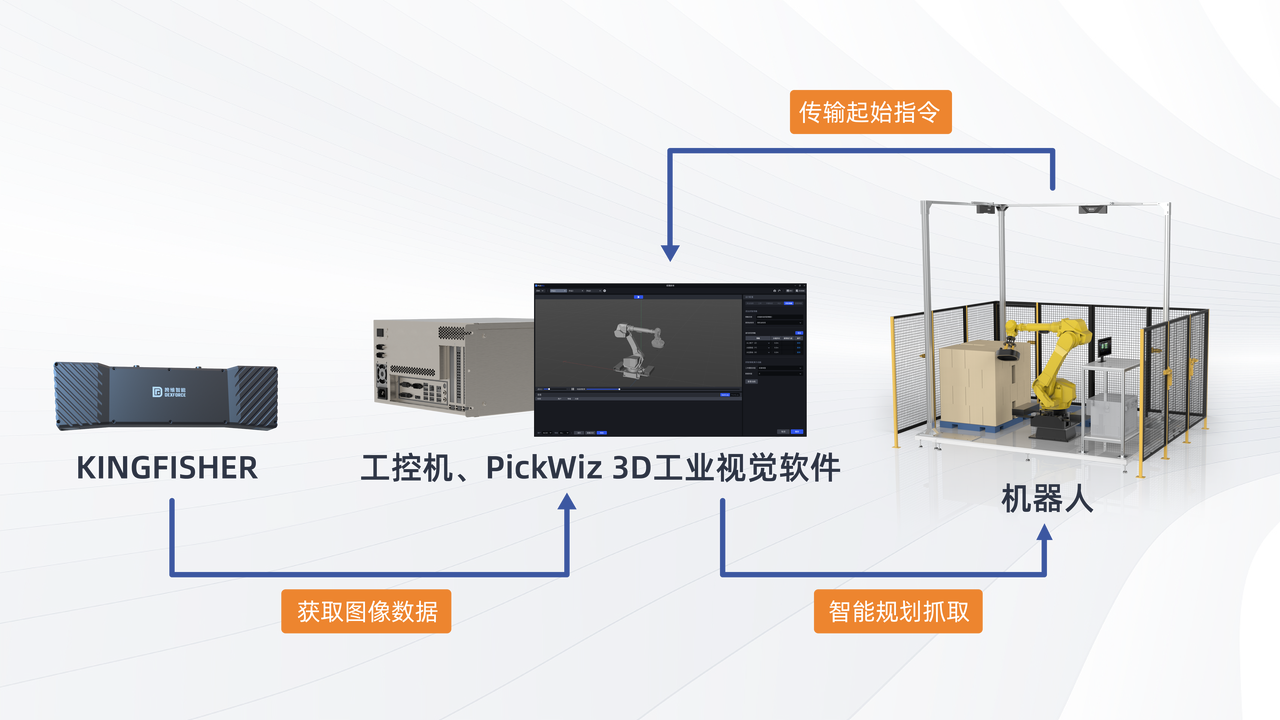
Robot
Robot is a programmed mechanical device with a certain degree of autonomy that can perform tasks such as movement, operation or positioning. They perform tasks based on the output from the visual system.
A Robot unit usually consists of a Robot body, a control cabinet and a teaching pendant.
In industrial applications that require a high degree of automation, a PLC (programmable logic controller) may be used to control the movement and operation of the Robot. When higher-level control and monitoring are required, Robot may also use a host computer to perform more complex programming and control of Robot, such as path planning, task scheduling, and motion control.
Camera
Camera refers to the 3D industrial Camera developed by Dexforce, which is used to collect images and position information of objects.
Industrial Computer
Refers to the computer equipment that provides the operating environment for Dexforce.
You can use the industrial computer provided by Dexforce (recommended), or use your own equipment as the industrial computer. For more information about industrial computers, please refer to: [Industrial Computer Configuration Instructions] (../../../其他/工控机配置说明.md).
2. Camera installation and connection
2.1 unpacking inspection
After receiving the Camera packaging box, please make sure that the packaging box is intact and not damaged.
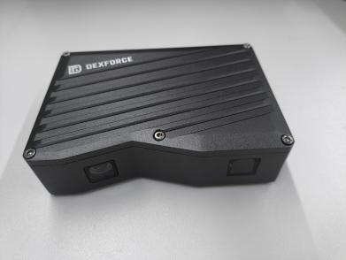
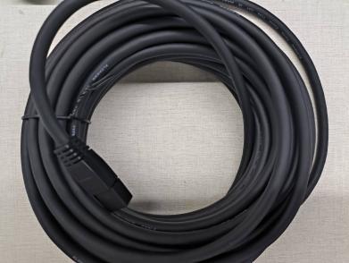
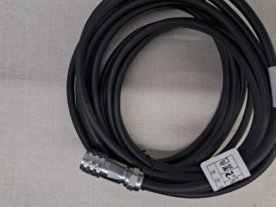
The picture below shows an example of the items and accessories included in the Camera packaging box. It is for reference only. Please refer to the actual contract.

| Category | Name | Function |
|---|---|---|
| Camera component | 3DCamera | Collect images |
| Camera components | Standard gigabit network cable | Connect Camera and transmit data |
| Camera components | Standard power cord | Connect Camera, Camera power supply |
| Camera component | Adapt Calibration Board | Parameter check, Extrinsic Parameter correction |
If items are damaged or missing, please contact Dexforce.
2.2 Camera connected to industrial computer
(1) Select a suitable Camera bracket and use the Camera connector to fix the Camera on the Camera bracket. After the Camera is installed, remove the lens protective film.
Camera connector (black sheet metal parts) drawing: drawing.STEP
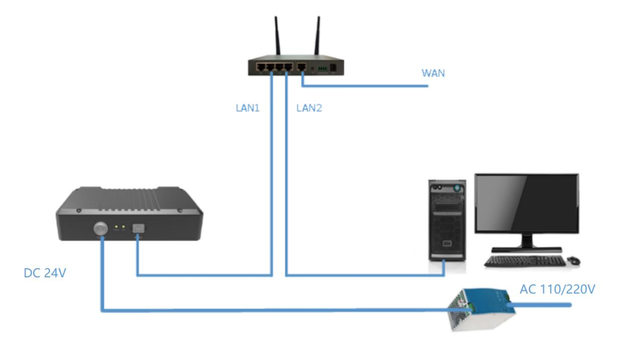
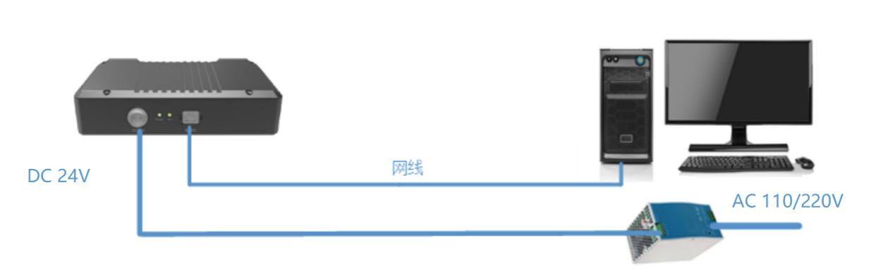
(2) Connect the network cable, connect one end of the network cable to the Camera, and the other end directly to the industrial computer or interact via a router.
(3) Connect the power supply, plug one end directly into the Camera power interface, and connect the other end to the 220v power supply.
The following is a schematic diagram of Camera wiring.
2.3 Camera connected to PickWiz
Please refer to [Camera Connection and Parameter Adjustment Guide] (相机连接与调参指南.md)
3. Robot installation and connection
3.1 Robot installation
(1) Connect the robot arm body to the Robot control cabinet
The robot arm body and the control cabinet are connected using cables. When connecting, they need to be inserted in the correct direction and slowly.
(2) Connect the Robot teaching pendant to the control cabinet
Plug the teach pendant cable into the control cabinet port, and then place the teach pendant directly above the control cabinet.
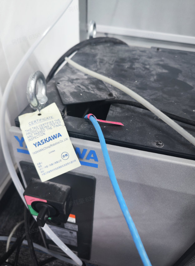
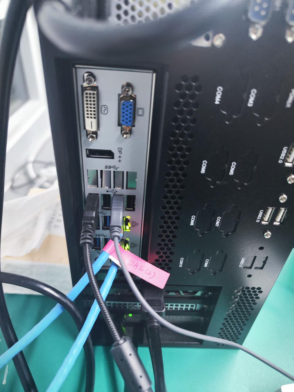
(3) Connect the network cable to the Robot control cabinet and industrial computer, as shown in the figure below.
(4) Power on the control cabinet
The control cabinet is powered on and the teaching pendant is turned on to put the Robot into working condition.
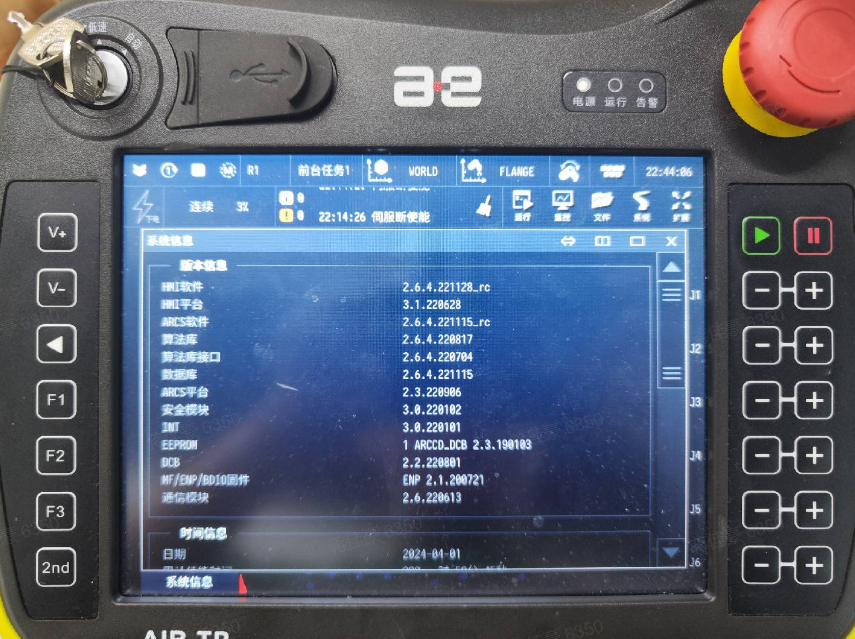
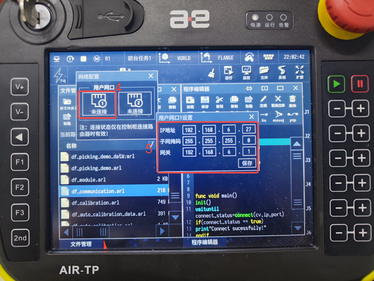
3.2 Check Robot system environment
Teach pendant connection status
Control cabinet network port and industrial computer network cable connection status
Are the network segments the same?
Whether to enable TCP network communication package
Robot system version
3.3 Robot connects to PickWiz
(1) Please refer to Robot Configuration and Communication Operation Guide to connect Robot and PickWiz communication
3.4 communication test
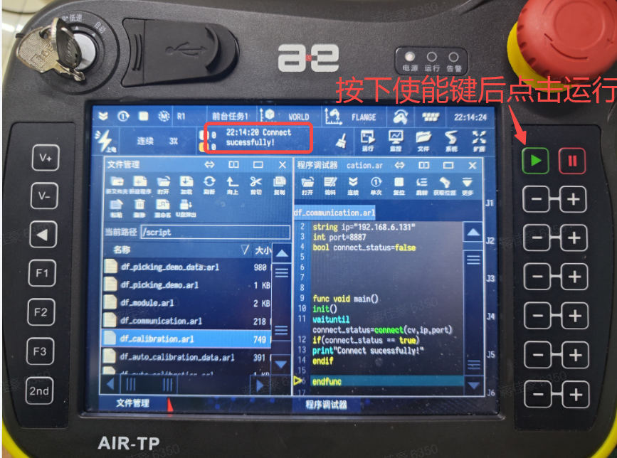
(1) Switch the program and select the communication test file df_communication.arl
(2) Modify the IP and port of the global variables at the top of the program to synchronize with the industrial computer
(3) Single step/continuous operation
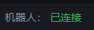
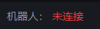
(4) View the Pickwiz, run to the connect function, the robot icon shows that it is connected, and when running to close the connection, the icon shows that it is not connected
(5) Check the teach pendant and the message "Connect successfully!" appears.