Visual Parameter Adjustment Operation Guide
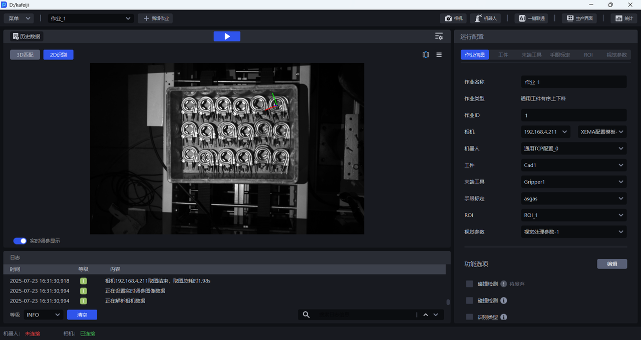
The software provides a visual parameter adjustment display function. In the visual parameter adjustment mode, the visual window can observe the visual results after parameter adjustment in real time, improving the ease of use and smoothness of adjusting the visual parameters. This article will introduce how to use the visual parameter display function.
1. Adjust visual parameters
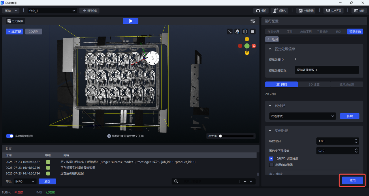
Open the Visual Parameter interface and modify the visual Parameters under 2D Recognition, 3D Calculation and Pick Point Processing. You can refer to the visual Parameter adjustment file for adjustment.
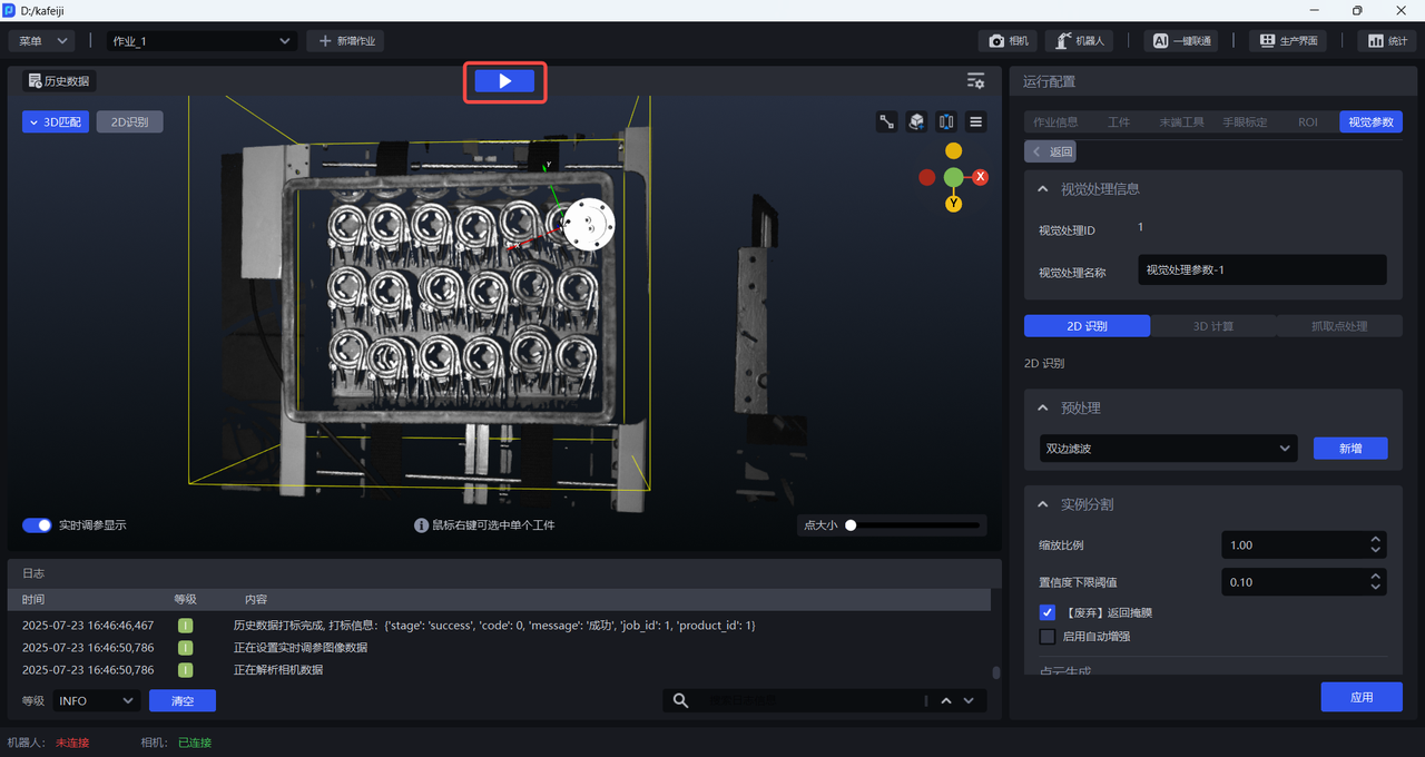
After adjusting the visual parameters, click the Run button/Run historical data on the main interface to view the processing process of the visual results after adjusting the parameters in the visualization window.
2. Visualization window
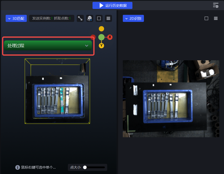
The visualization window includes two windows, 3D Matching and 2D Recognition, and a Processing floating window. Process will appear after running and can be expanded and collapsed by clicking on it.
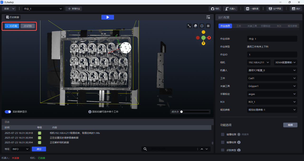
(1) Window split/merge
Click the Window Split Button to split the window into a 3D matching window and a 2D recognition window, as shown in the figure below.
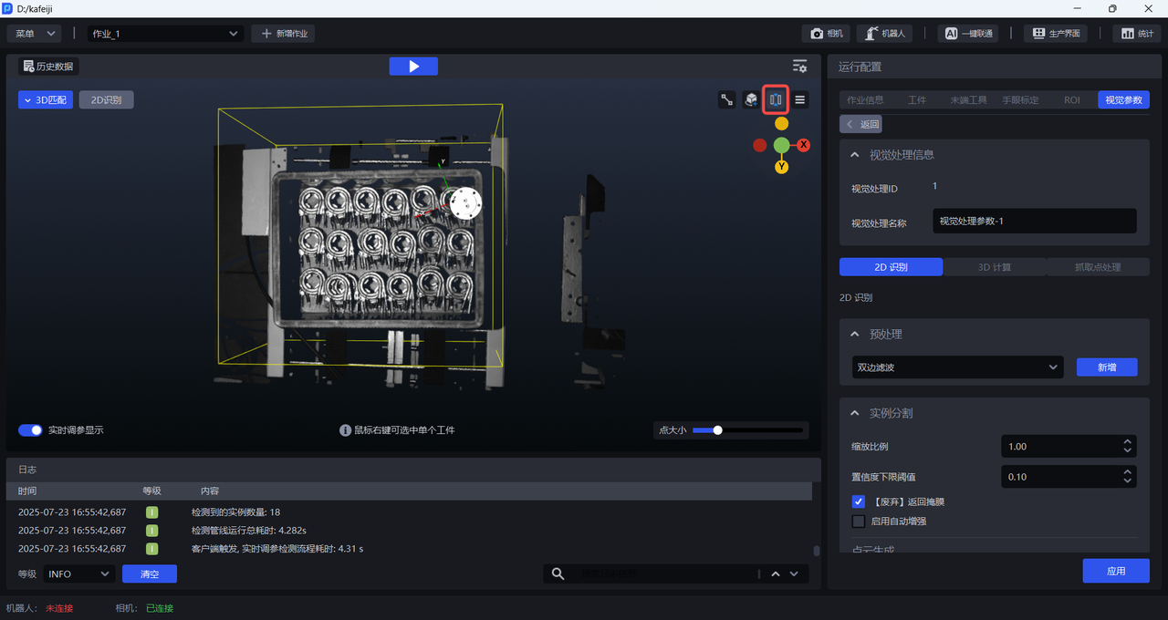
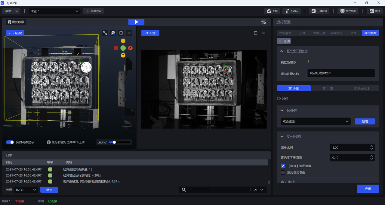
Click the Window merge button to merge windows, as shown in the figure below.
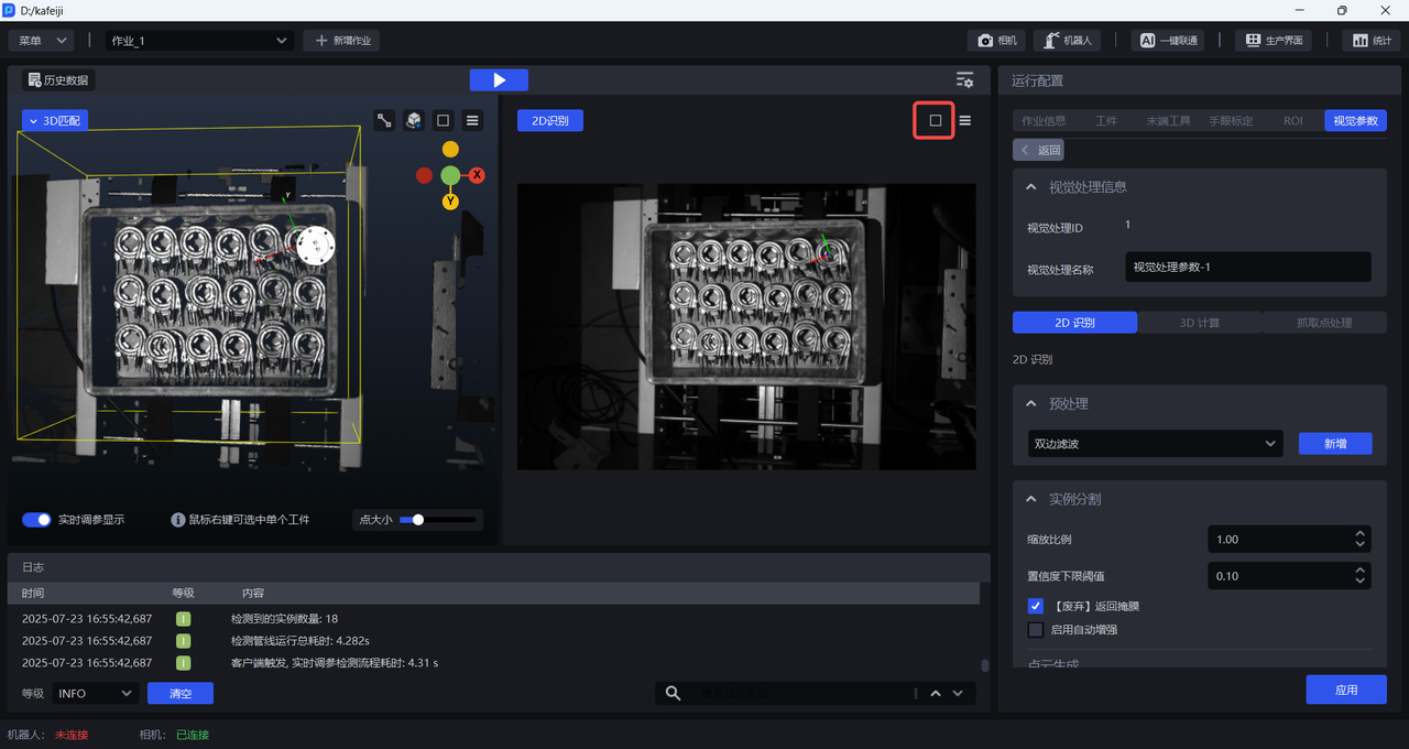
(2)Set the background color of the 3D Match window
The background color of the 3D matching window can be modified to facilitate observation of the ScenePoint Cloud. The default window color is dark gray. If the ScenePoint Cloud is darker, it will be difficult to observe the ScenePoint Cloud, so you can modify the background color of the window.
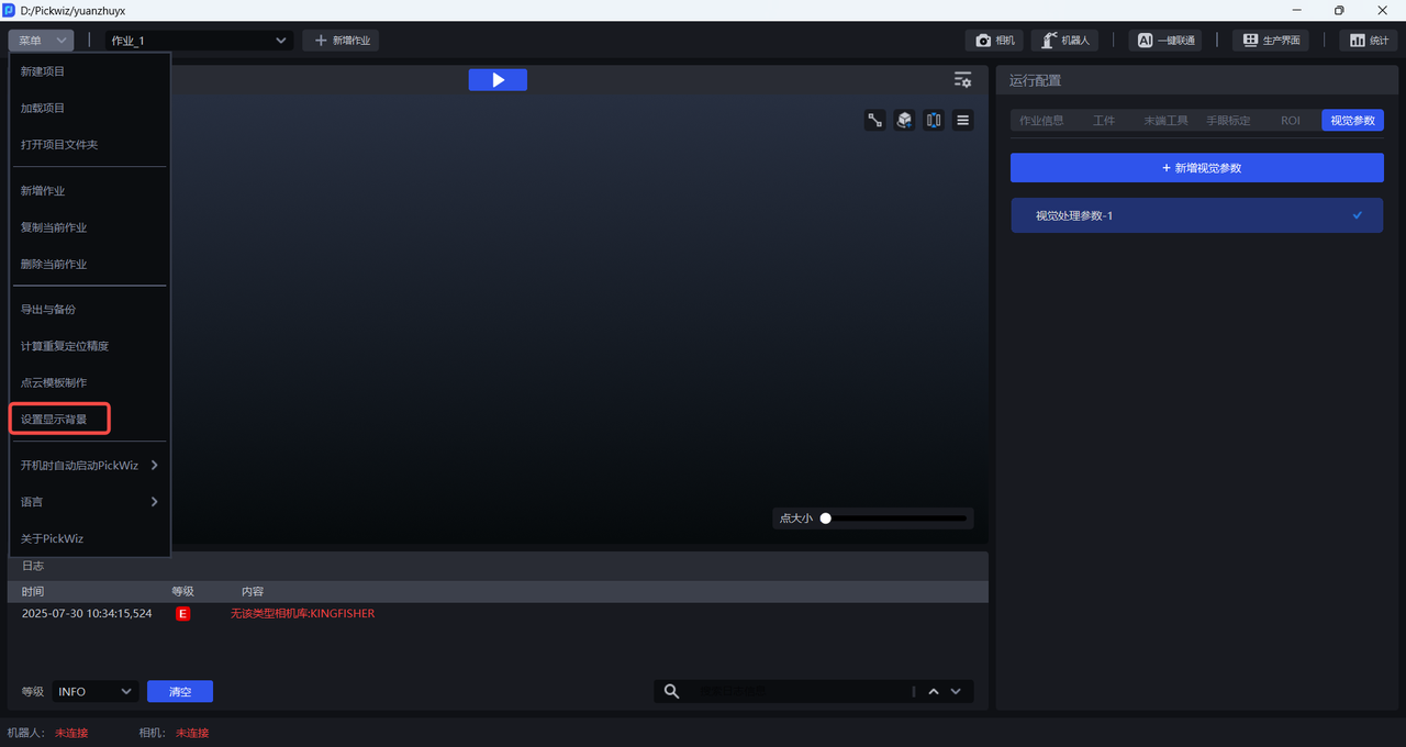
Click Menu>Set Display Background, and the Set Display Background pop-up window will appear, as shown in the figure below.
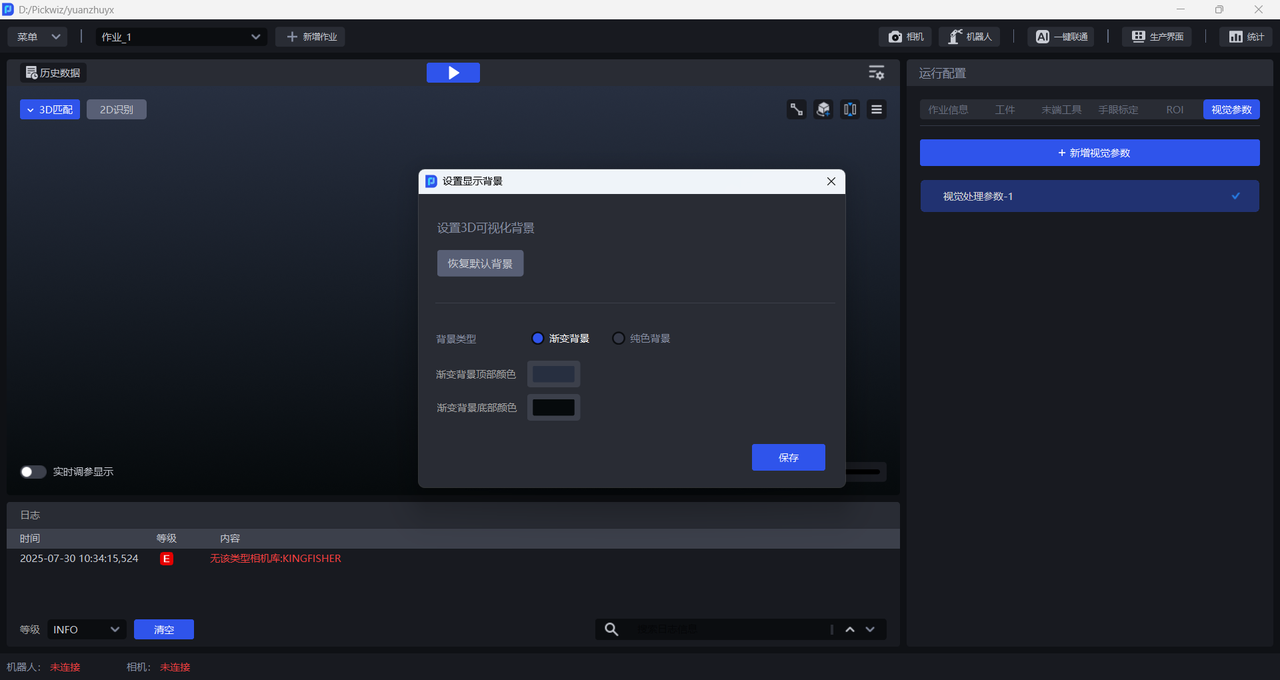
The 3D Match window can be set to a solid color or gradient background, as shown in the figure below.
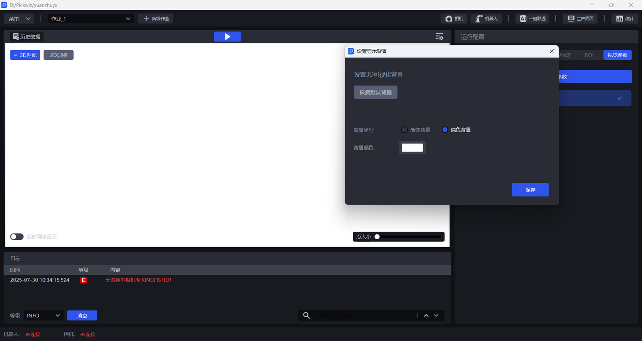
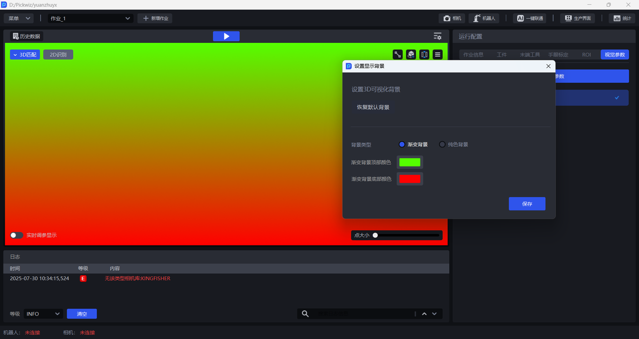
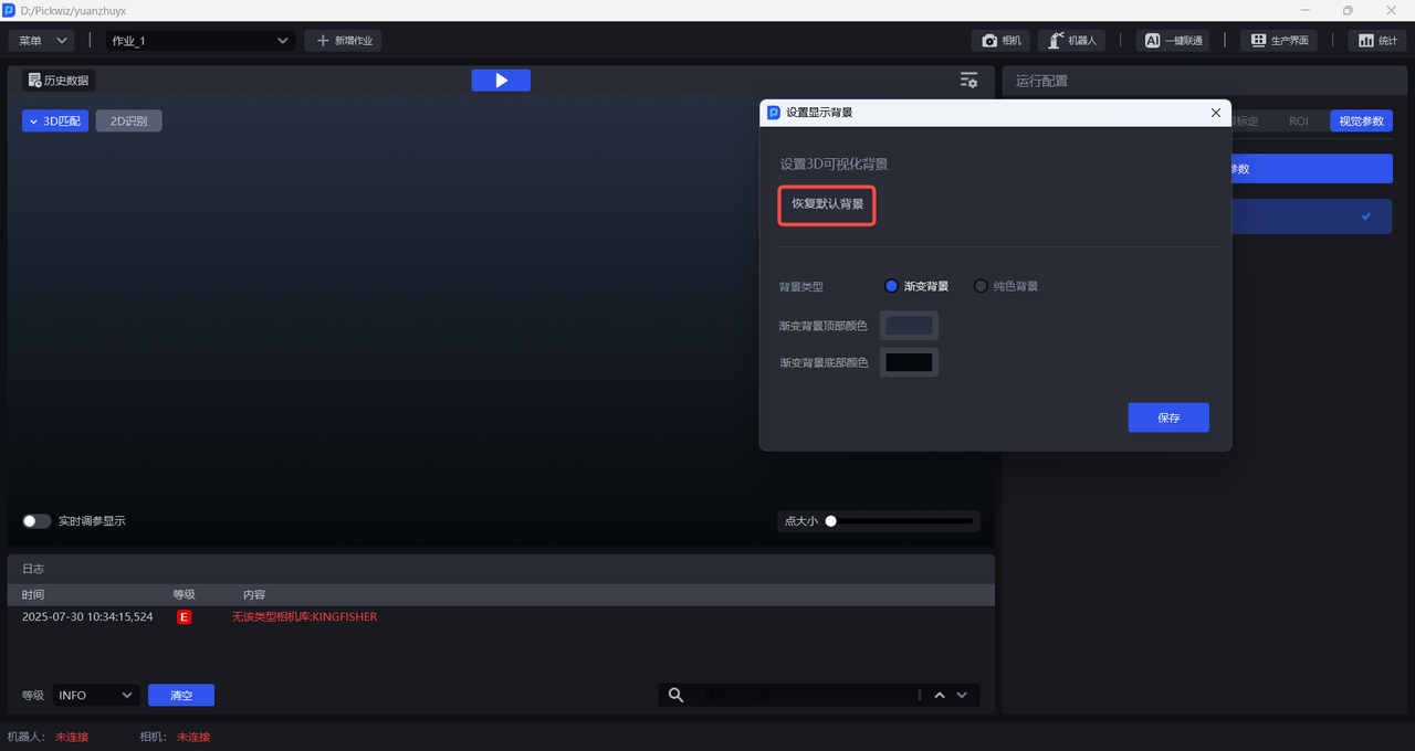
Click Restore Default Background to restore the 3D Matching window to the default dark gray, as shown in the figure below.
(3)View Process
After a task is triggered to run or is run using historical data, the function's processing will automatically appear.
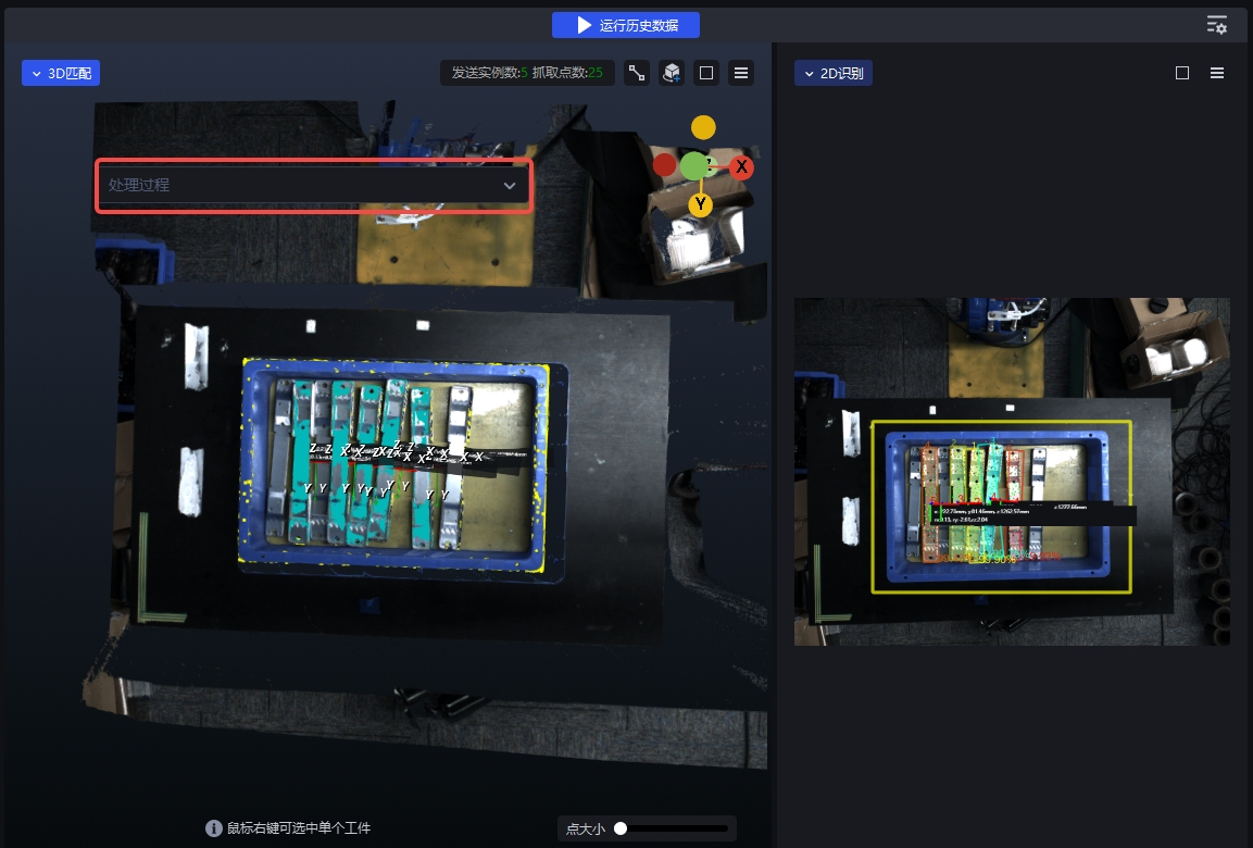
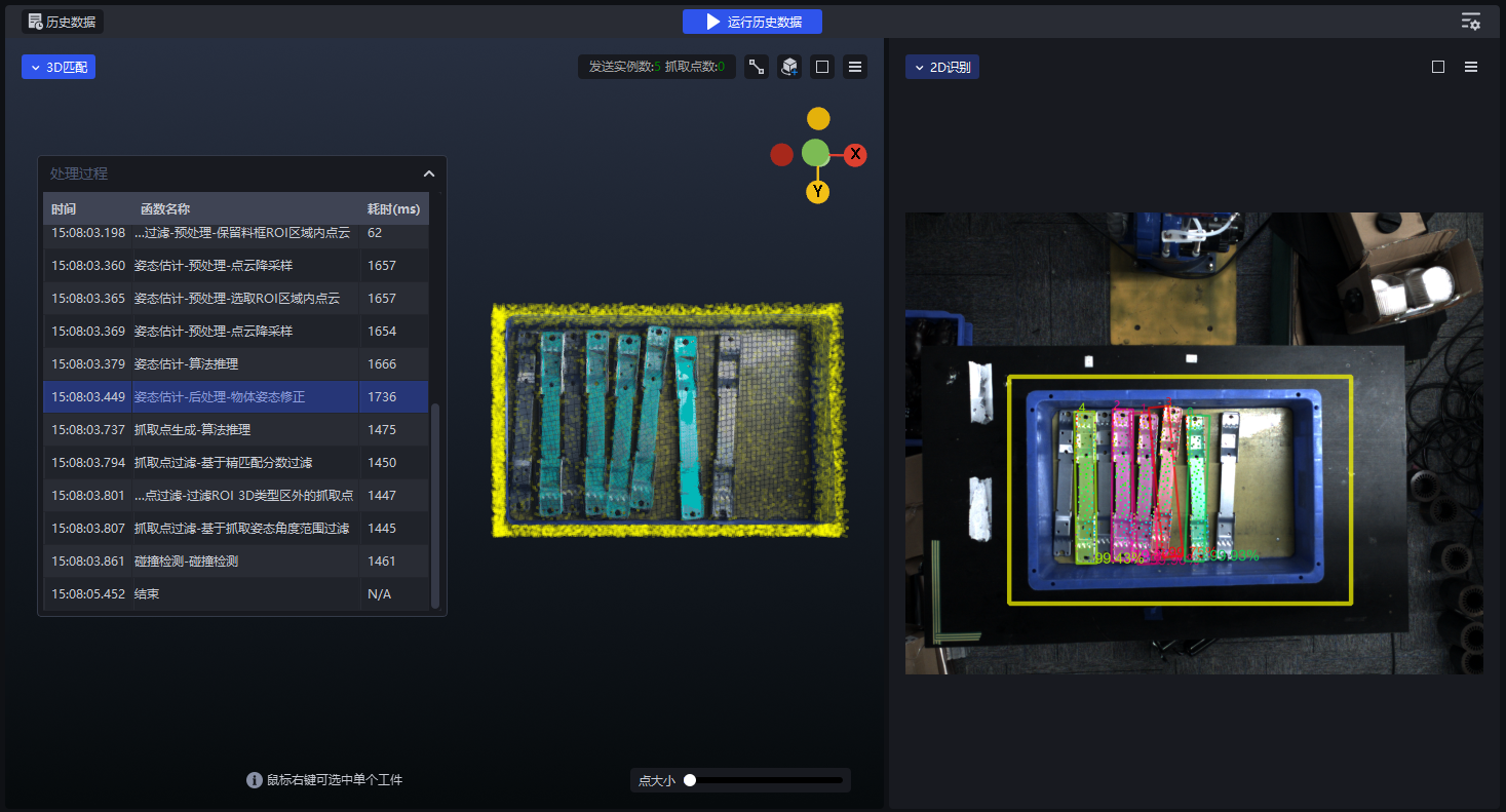
Click to expand Processing, and you can see the total collection of functions that have been experienced, including the name of the function, the processing time to start entering the function (milliseconds), and the processing time of the function (milliseconds)
Click on any function you have experienced, and you can see in the 2D and 3D windows the 3D matching effect and 2D recognition effect after superimposition of these functions from the first function to the currently clicked function.
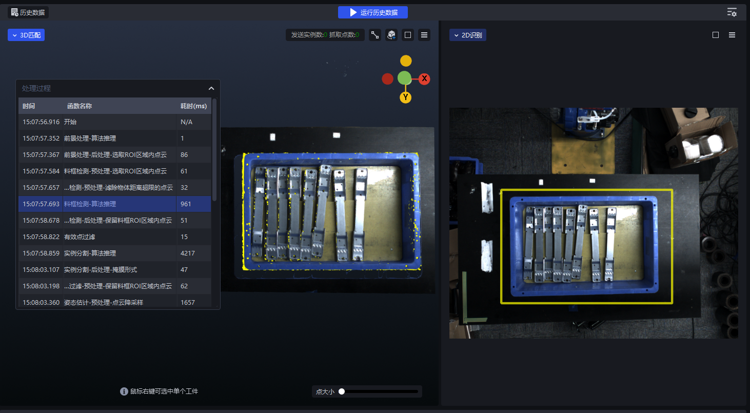
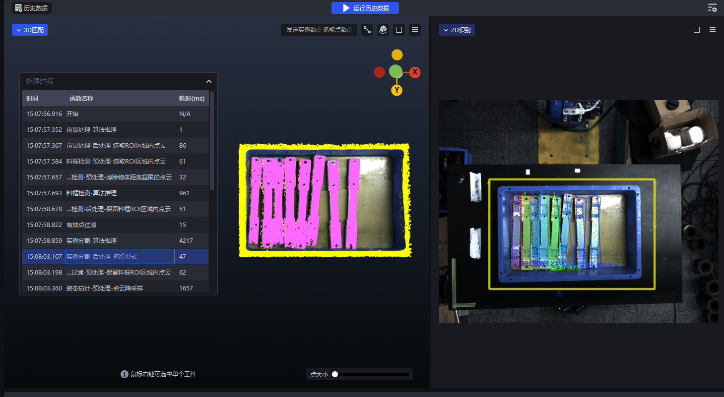
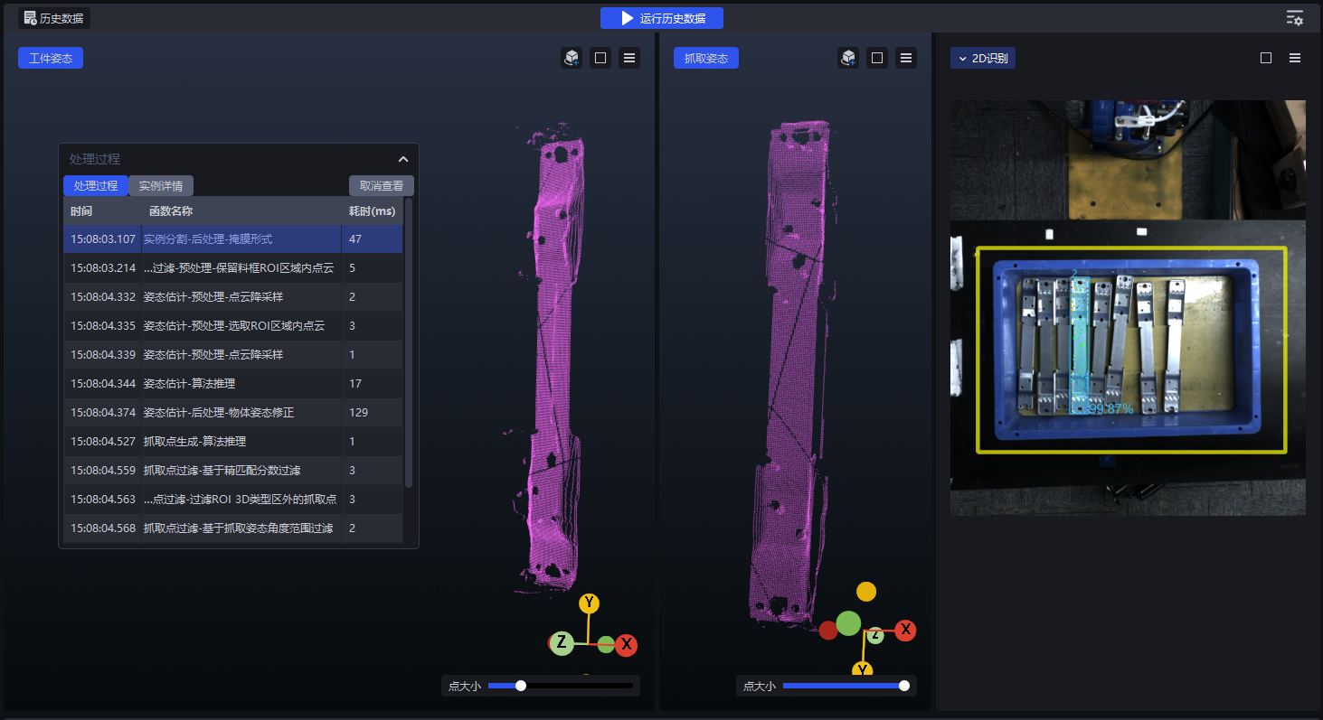
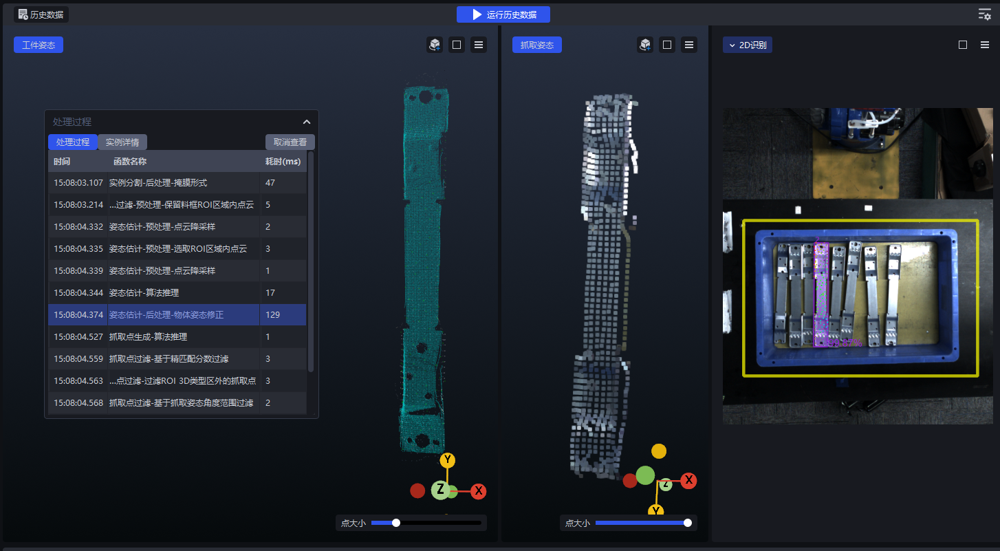
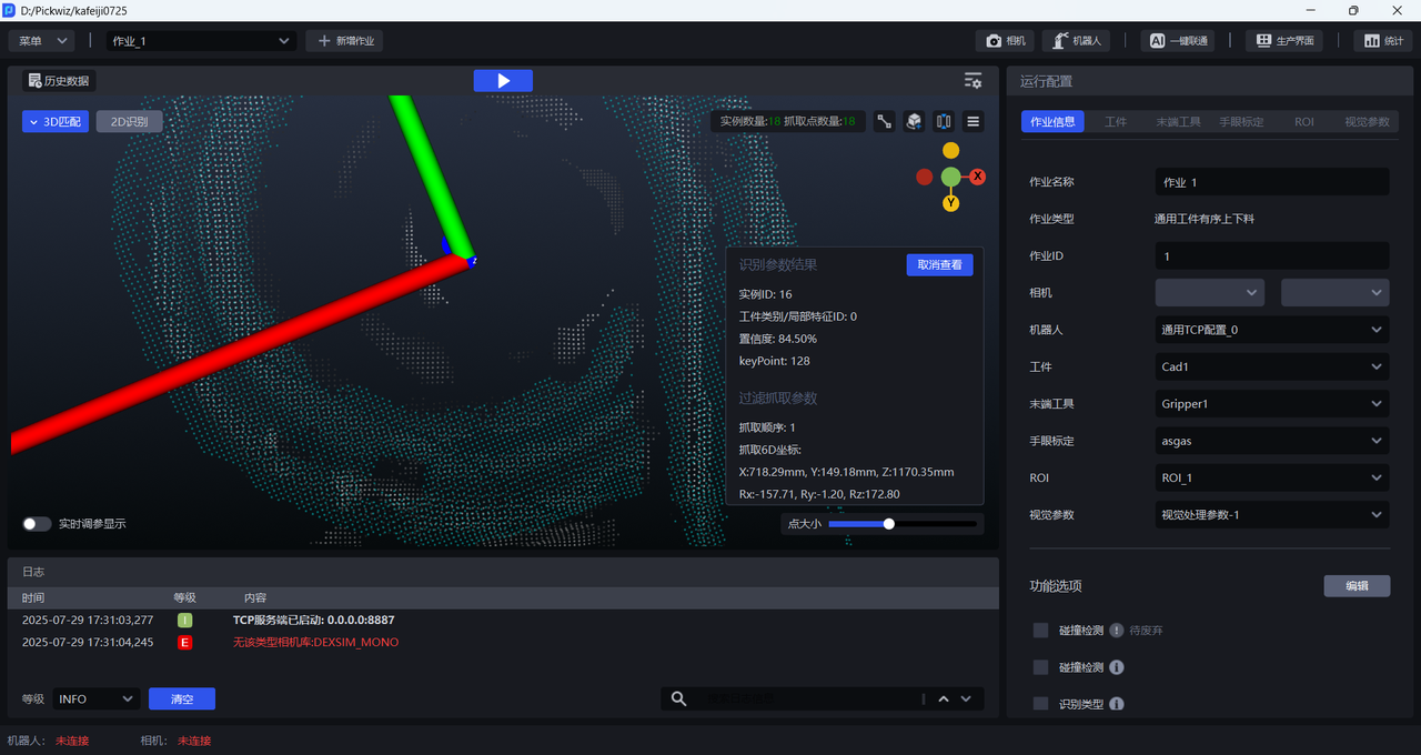
By right-clicking on a specific instance in the 3D matching window, you can individually view the Target posture Point Cloud, grabbing posture Point Cloud, and 2D recognition effect, and you can see the processing process and instance details of the Target instance. Click Cancel View to return to Scene.
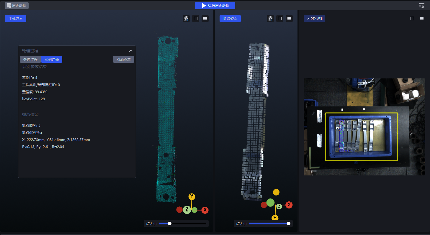
2.1 2D recognition
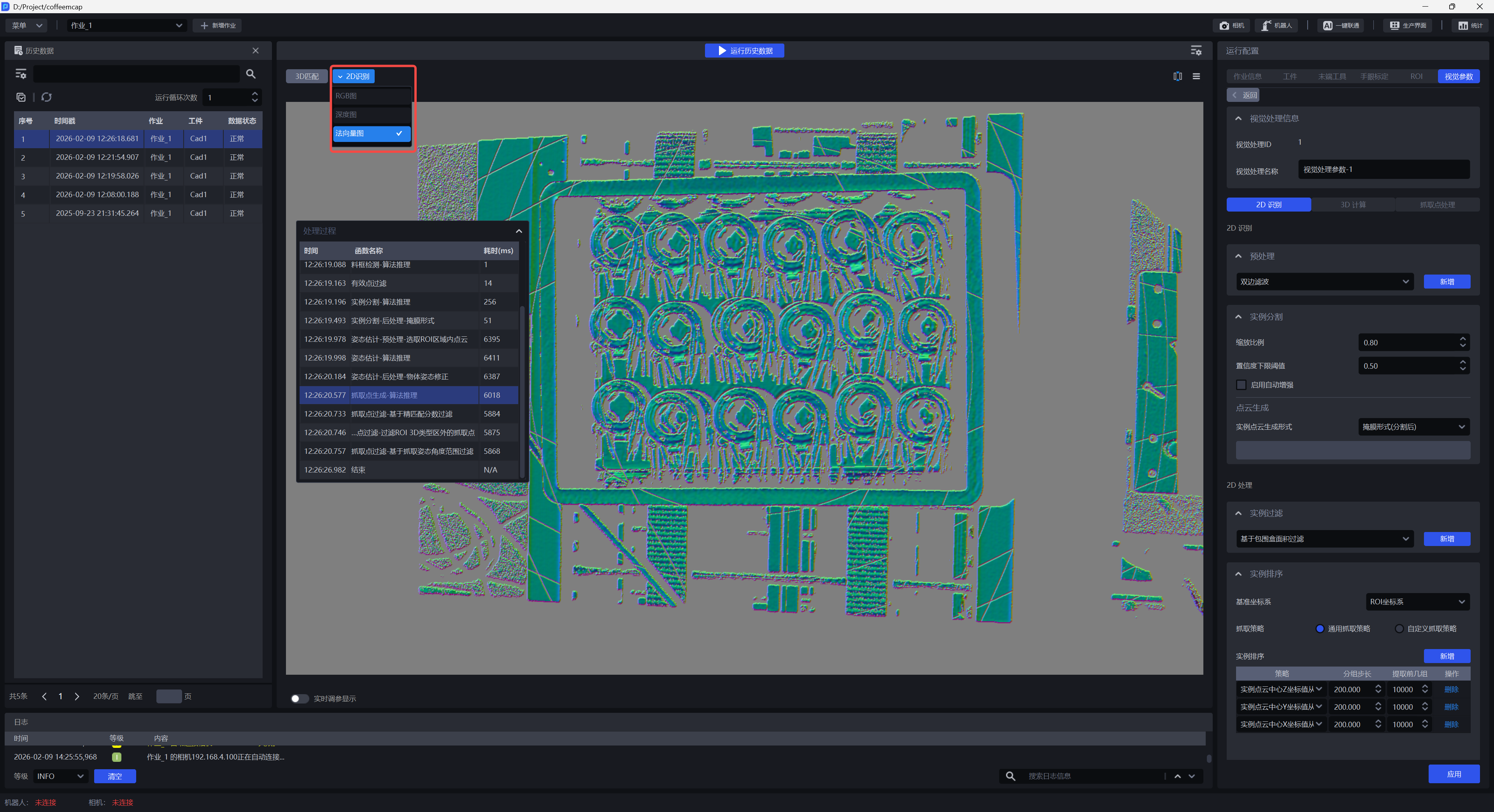
Click 2D recognition, and you can choose to view the RGB picture, Depth image and Normal vector diagram of 2D recognition.
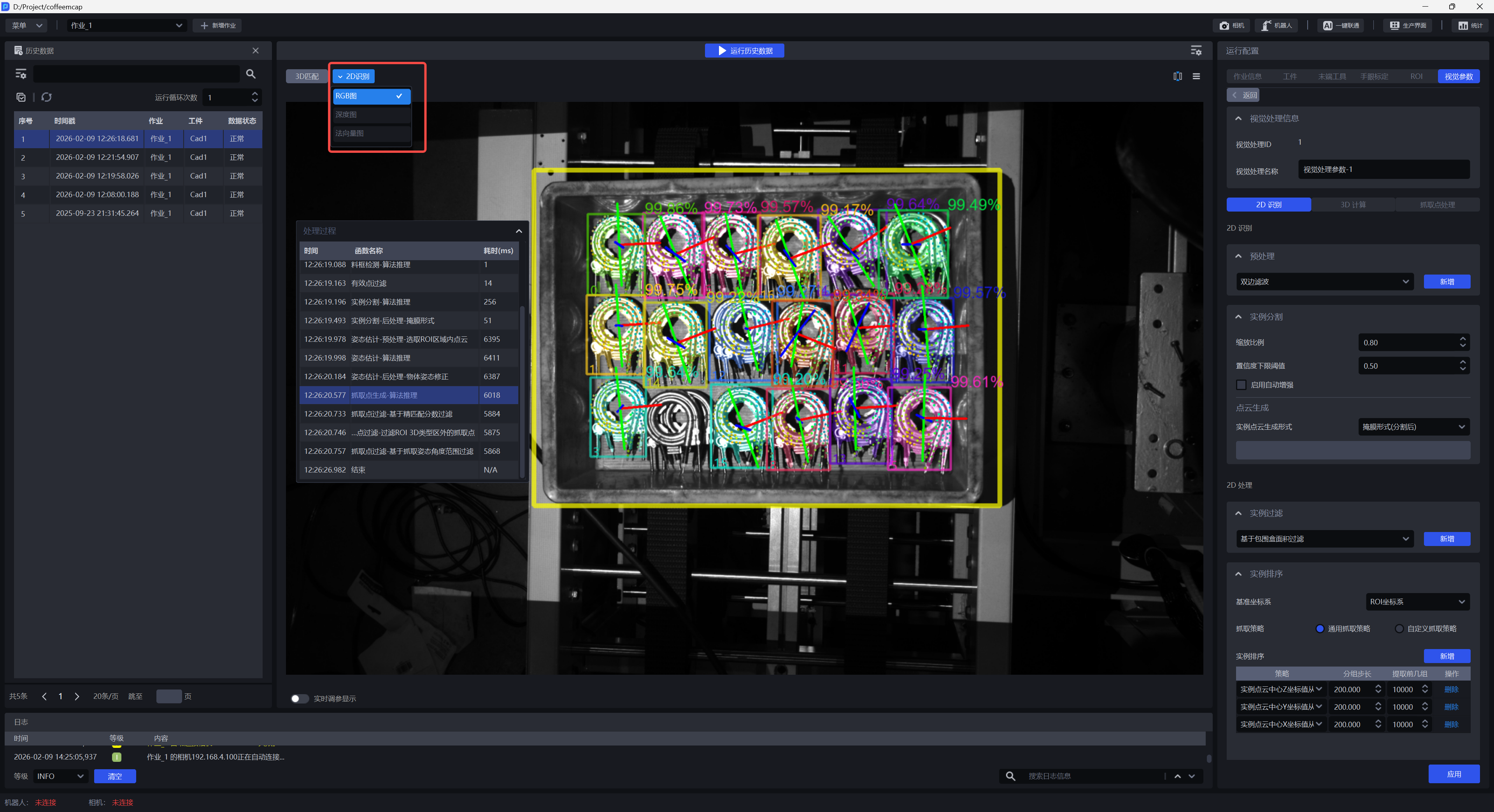
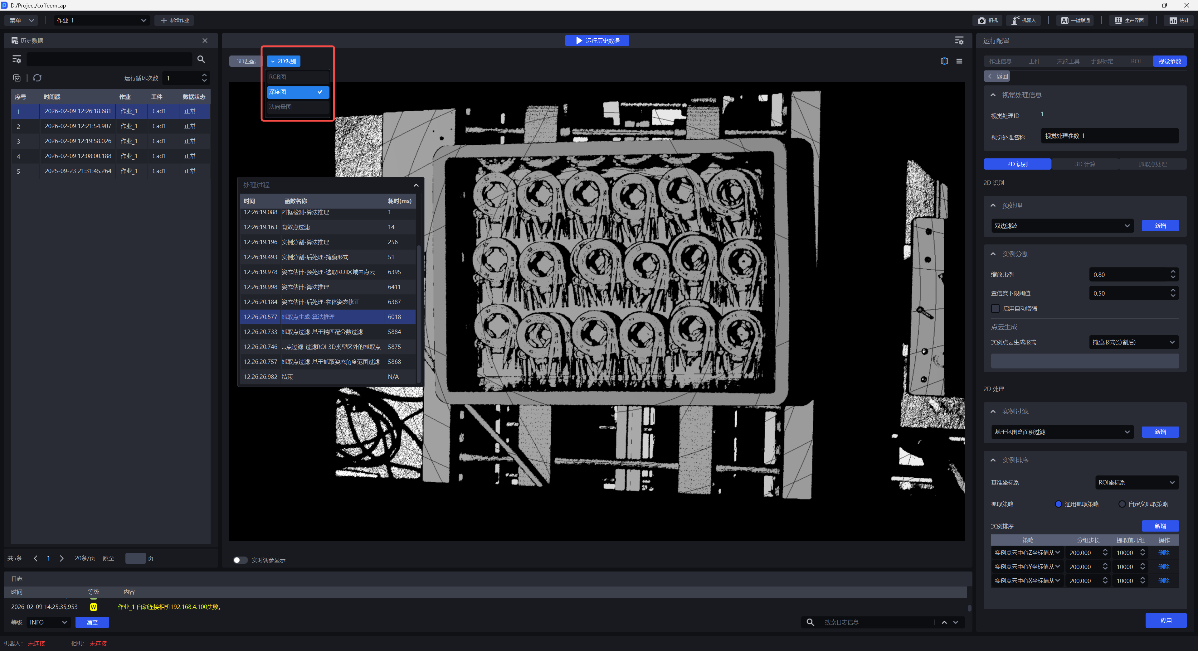
Depth image can be seen and configured in the two functions "Filling Depth image holes" and "Filtering Depth image by color" and the following functions.
Normal vector diagram can be seen and configured in the two functions "Depth to Normal vector diagram function" and "Calculate normal vector" and the following functions.
If there is no corresponding Depth image or Normal vector diagram, the corresponding options will not appear in the drop-down options.
Click the Settings button on the right side of the 2D Recognition window to select the displayed 2D visual results, as shown in the figure below.
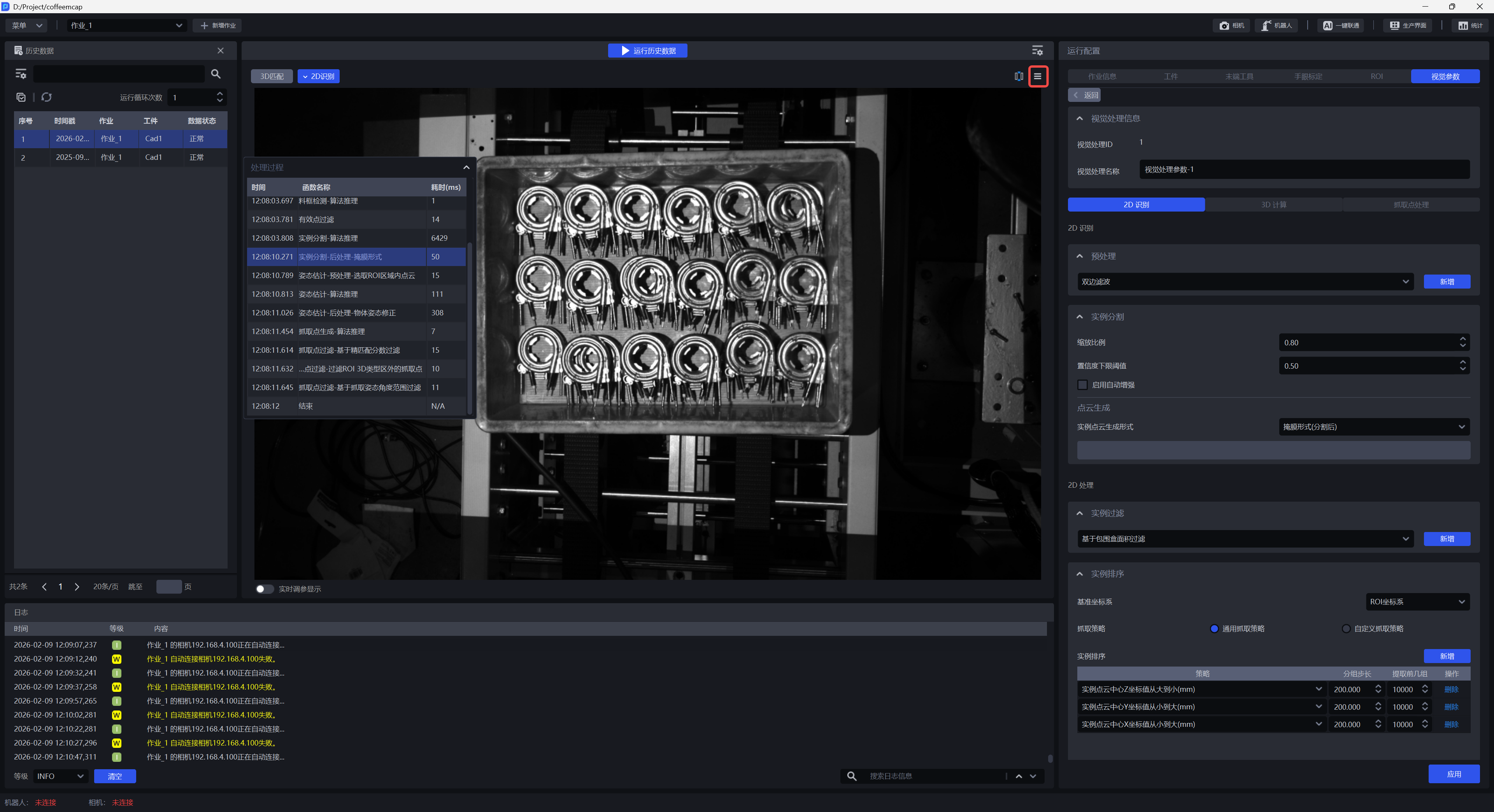
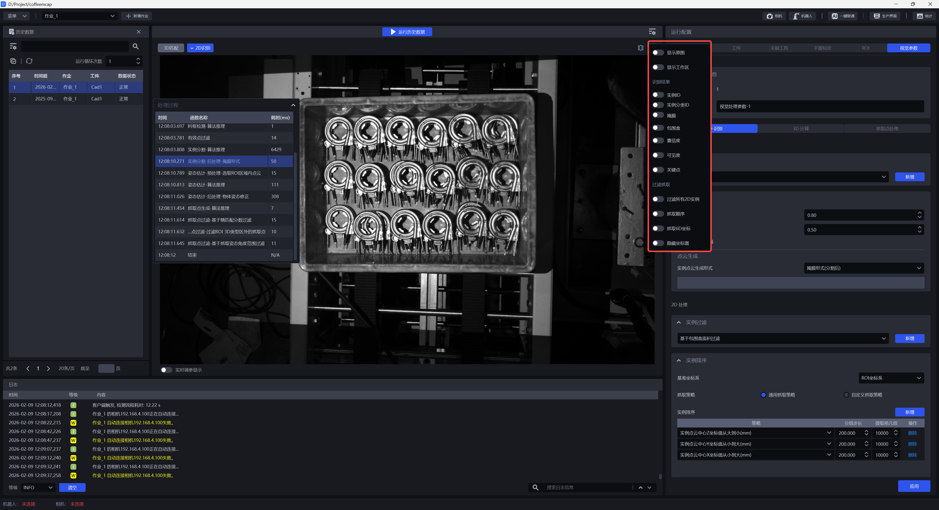
2.1.1 Show original image
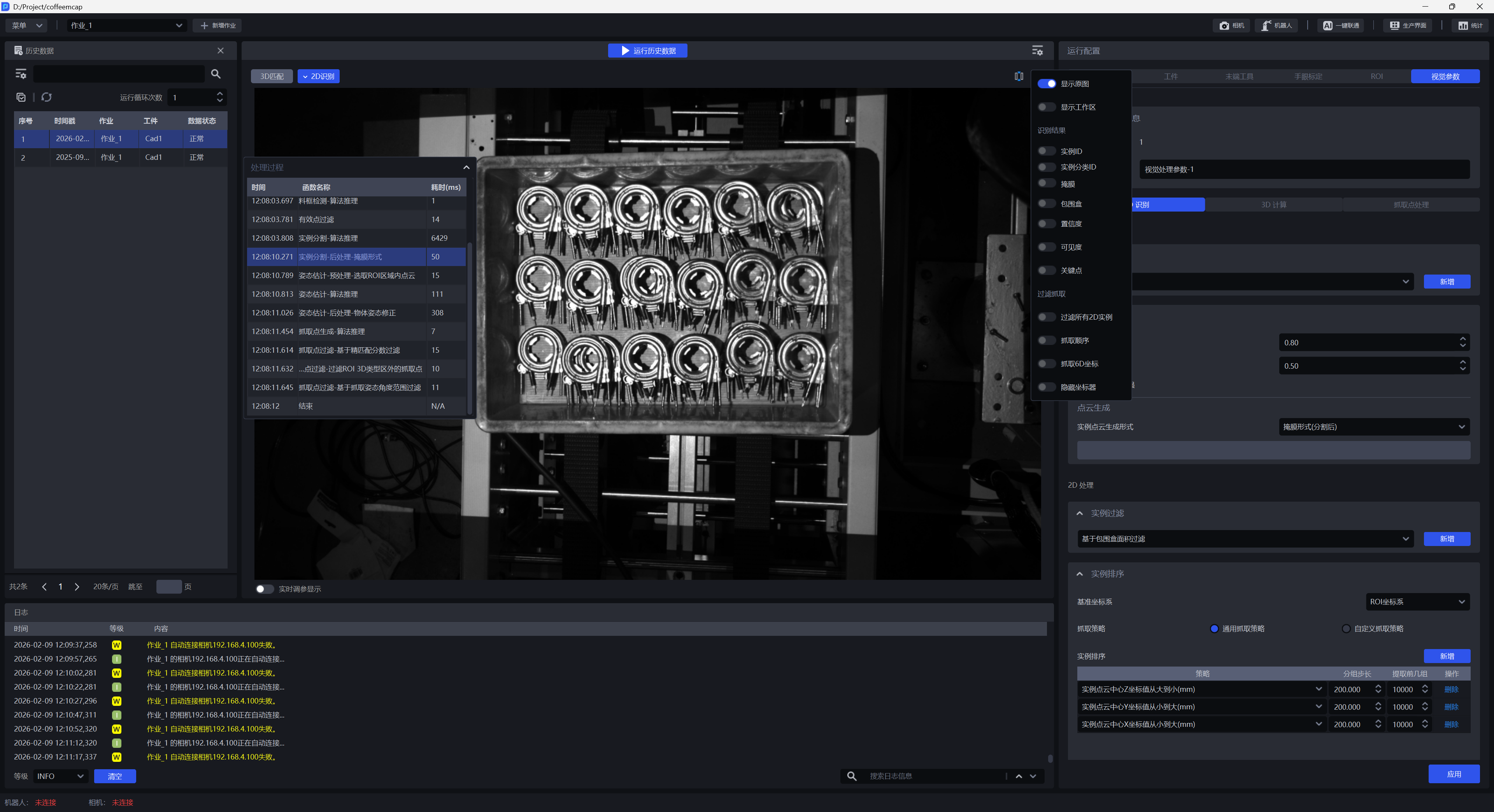
Turn on Show original image. After turning it on, only the 2D image collected by the Camera will be displayed. No visual results will be displayed, and other setting items cannot be turned on.
2.1.2 Display work area
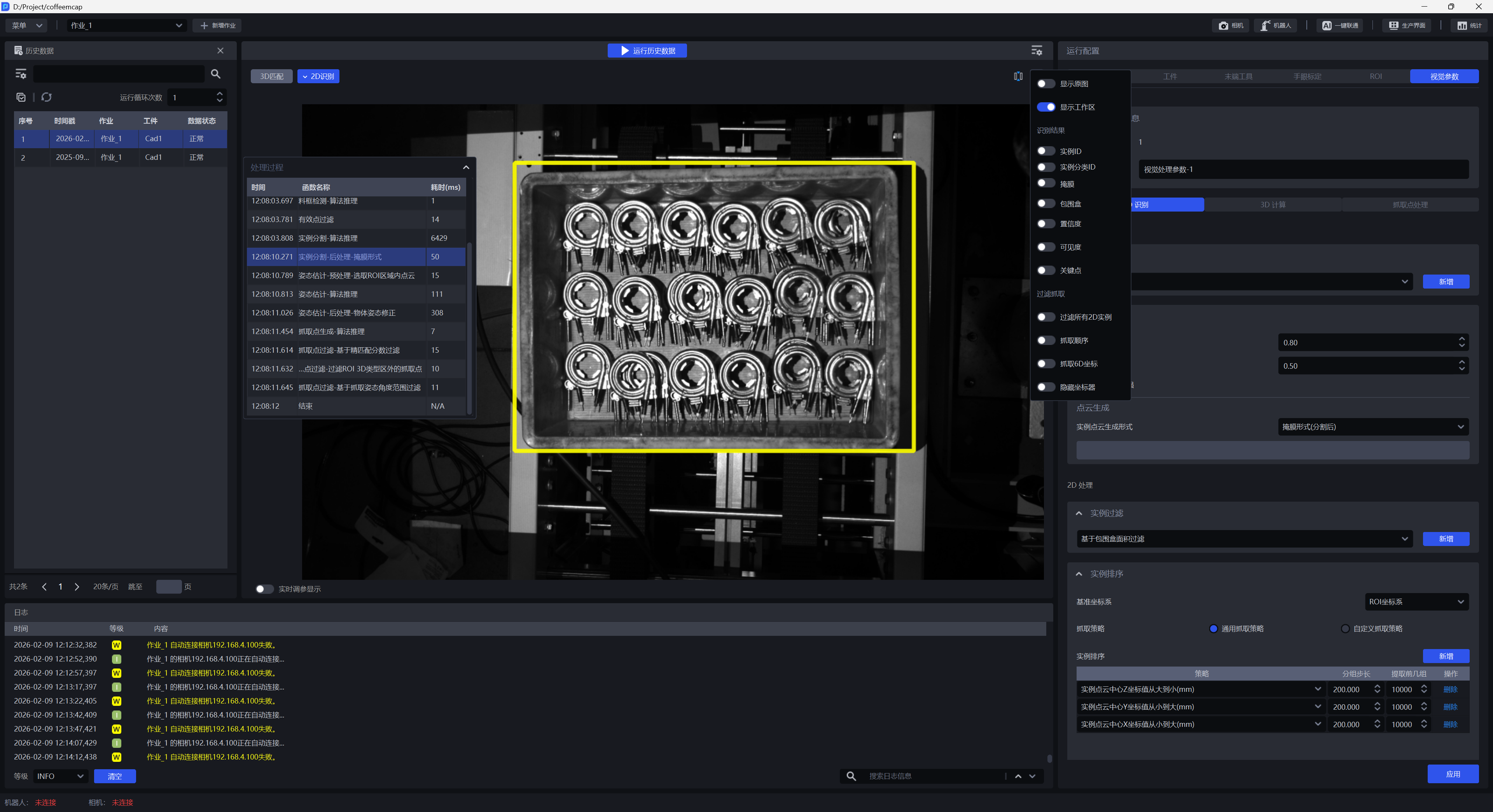
Turn on Show Workspace. After turning it on, only the ROI 2D workspace will be displayed, as shown in the figure below.
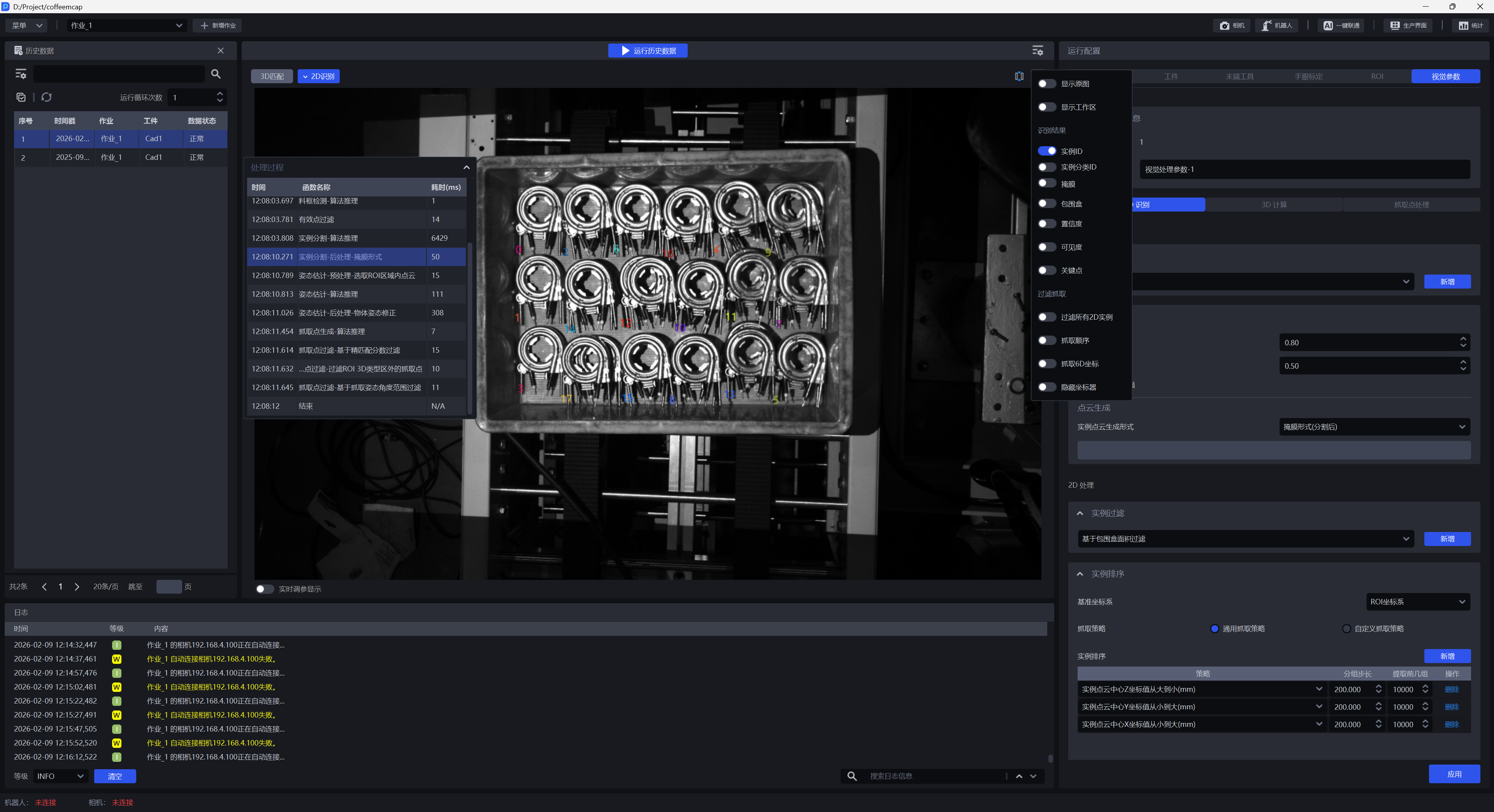
2.1.3 instance ID
Turn on Instance ID. After turning it on, the unique identifier of the identified Target instance will be displayed, as shown in the figure below.
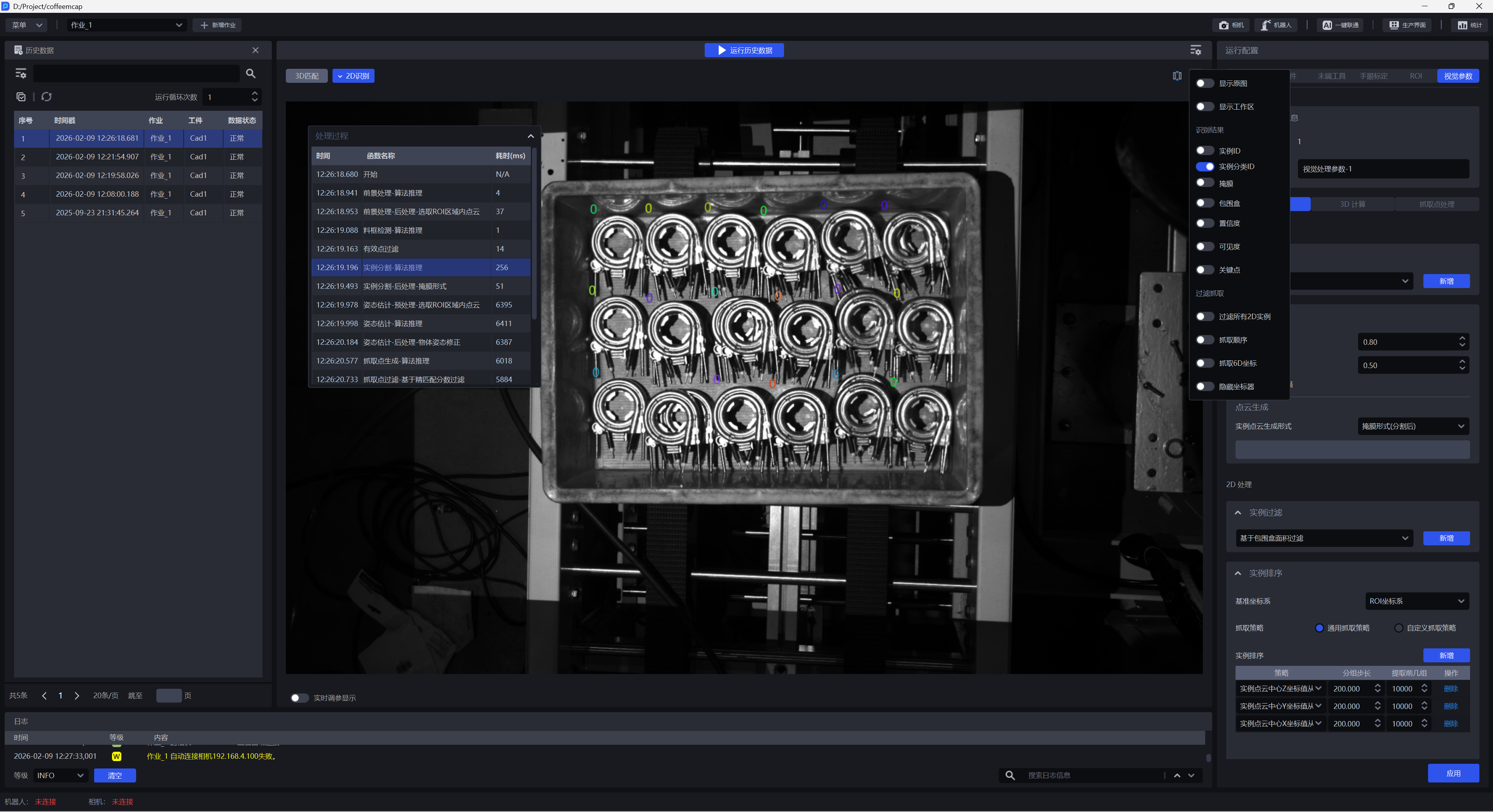
Turn on Instance ID Classification. After turning it on, the categories in which Targets are recognized will be displayed. Instances with category IDs of 0 will be retained by default.
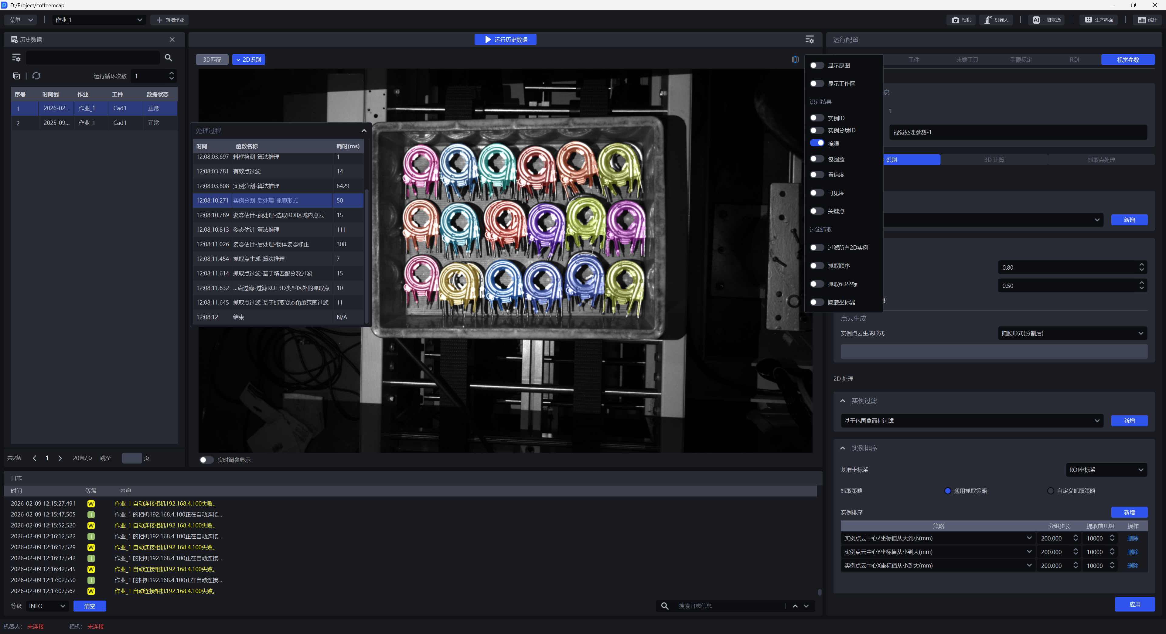
2.1.4 mask
Turn on Mask. After turning it on, the mask of the identified Target instance will be displayed, as shown in the figure below.
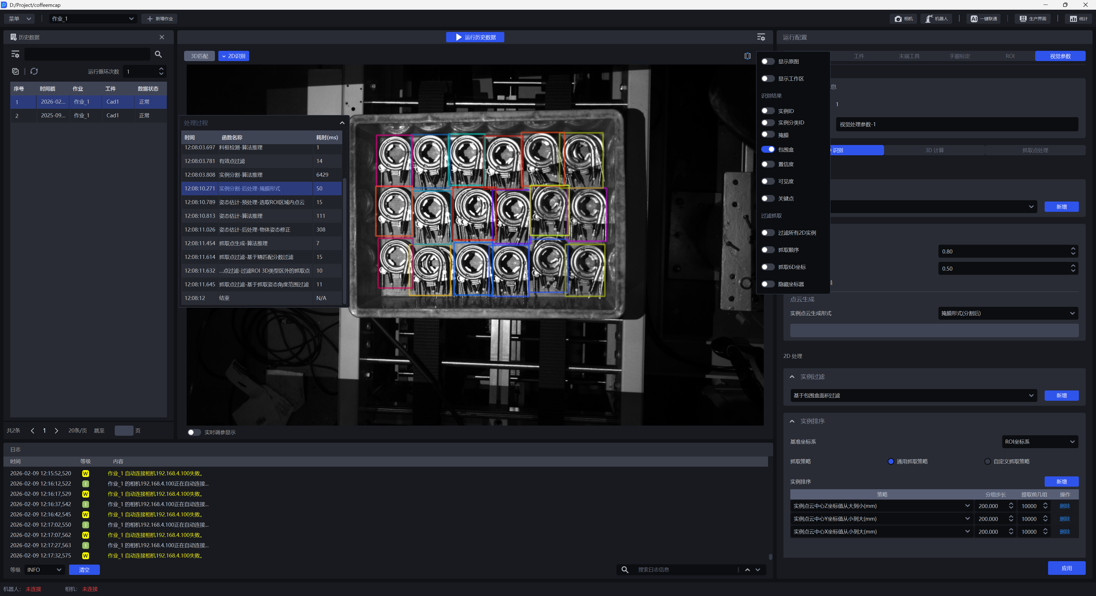
2.1.5 bounding box
Turn on Bounding Box. After turning it on, the bounding box of the recognized Target instance will be displayed, as shown in the figure below.
2.1.6 Confidence
Turn on Confidence. After turning it on, the Confidence of the identified Target instance will be displayed, as shown in the figure below.
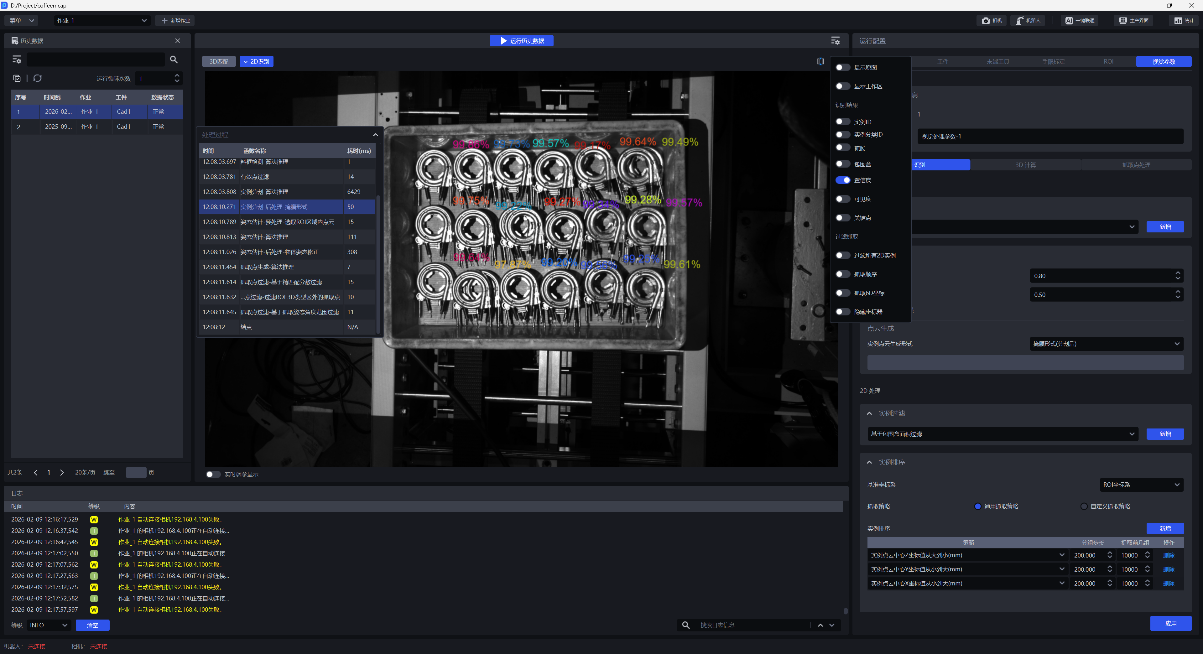
2.1.7 visibility
Turn on Visibility. After turning it on, the visibility of the identified Target instance will be displayed, as shown in the figure below.
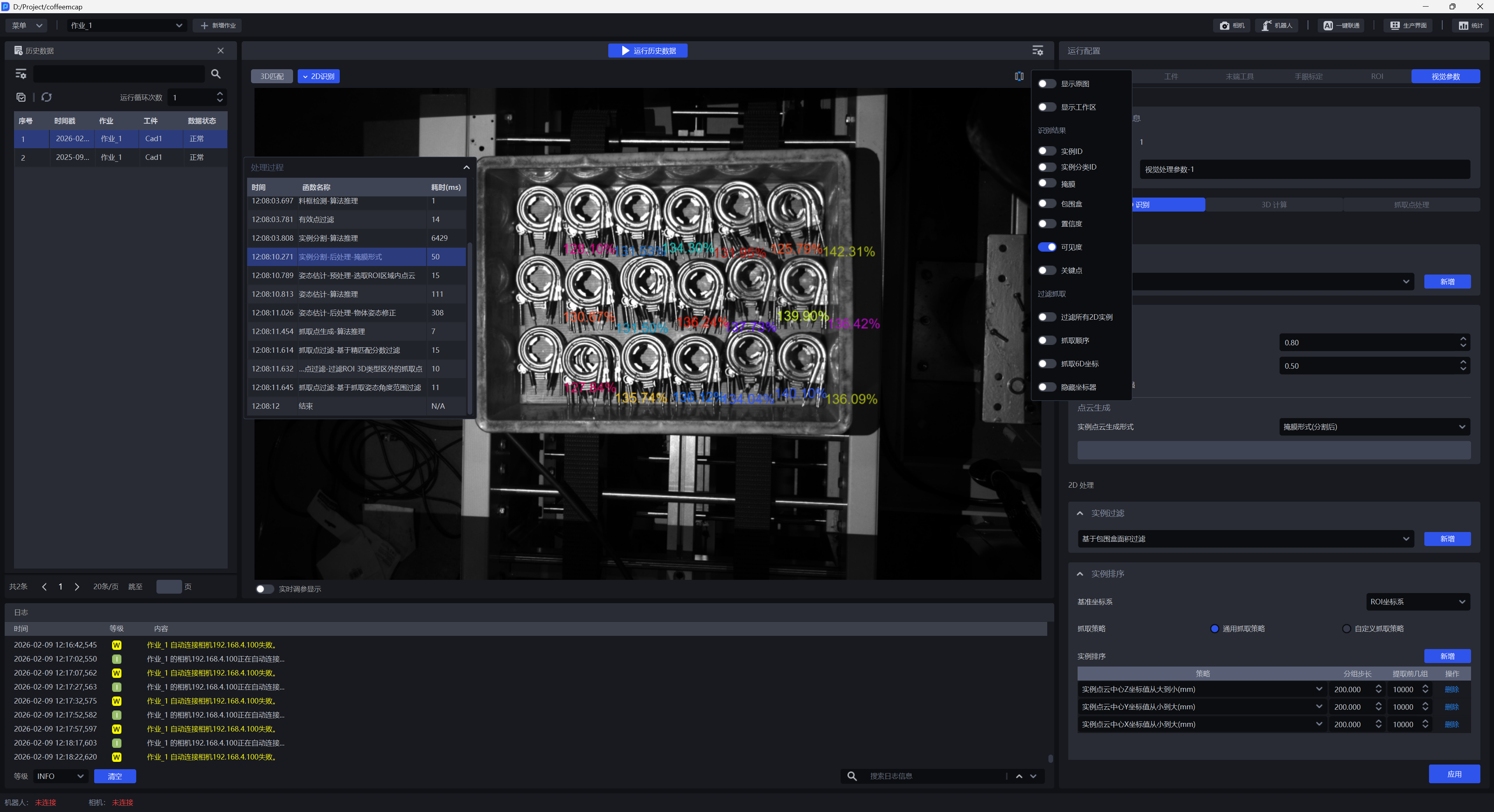
2.1.8 Key Points
Turn on Key Points. After turning it on, the key points of the identified Target instance will be displayed, as shown in the figure below.
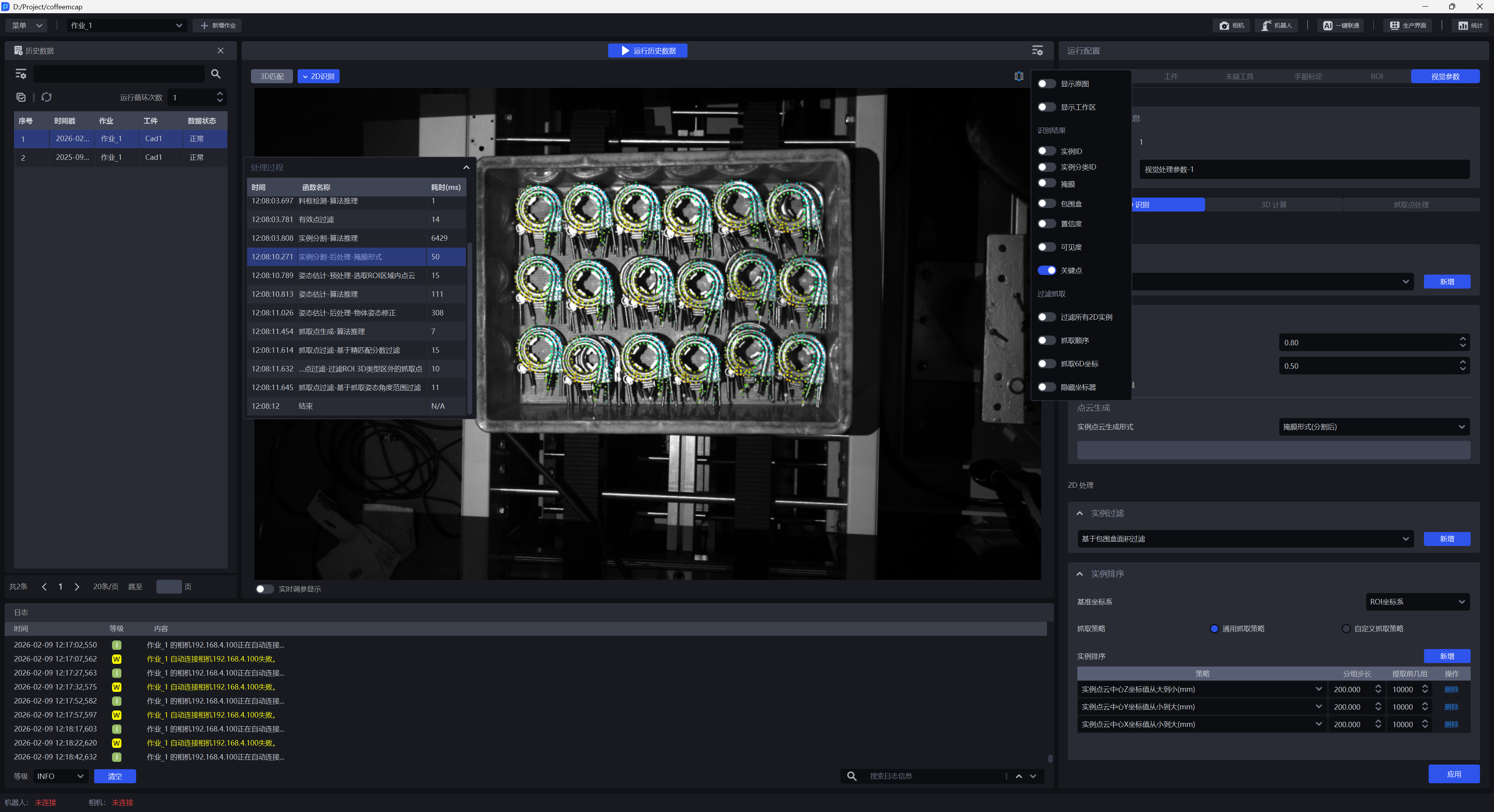
2.1.9 filters all 2D instances
When turned off, the instances identified by the Instance Segmentation node are displayed; when turned on, the instances filtered by the Instance Filtering node are displayed.
As shown in the figure below, the Filtering based on Confidence function is added to the instance filtering node, and the Reference Confidence is set to 0.7, so instances with Confidence less than 70% will be filtered.
When Filter all 2D instances is turned off, the instance Confidence in the red box in the figure below is 63.1% and is not filtered.
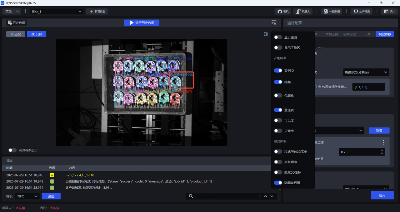
When Filter all 2D instances is turned on, the instance Confidence in the red box is 63.1% and will be filtered.
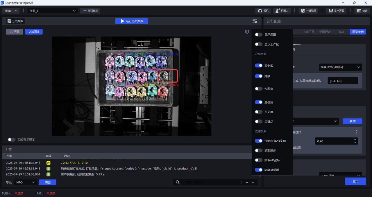
2.1.10 crawling order
Turn on Fetching Order. After turning it on, the fetching order of the identified Target instances will be displayed, as shown in the figure below.
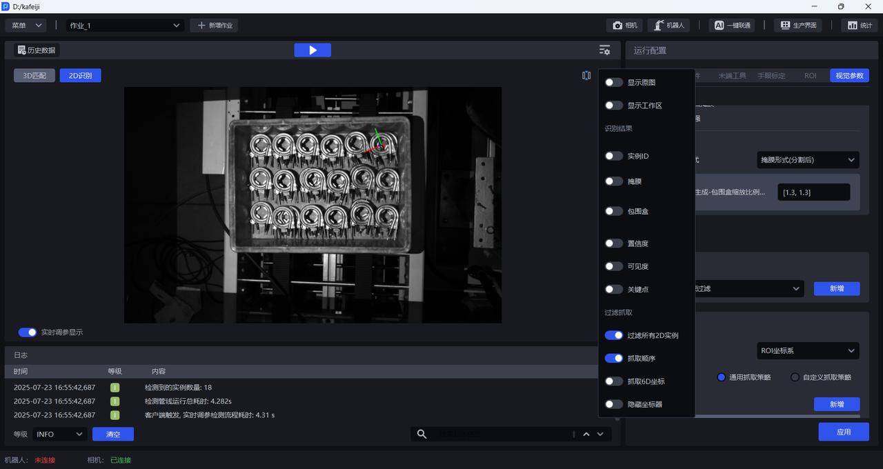
2.1.11 grab 6D coordinates
Turn on Grab 6D coordinates. After turning it on, the grabbing pose (i.e. 6D coordinates) of the recognized Target instance will be displayed, as shown in the figure below.
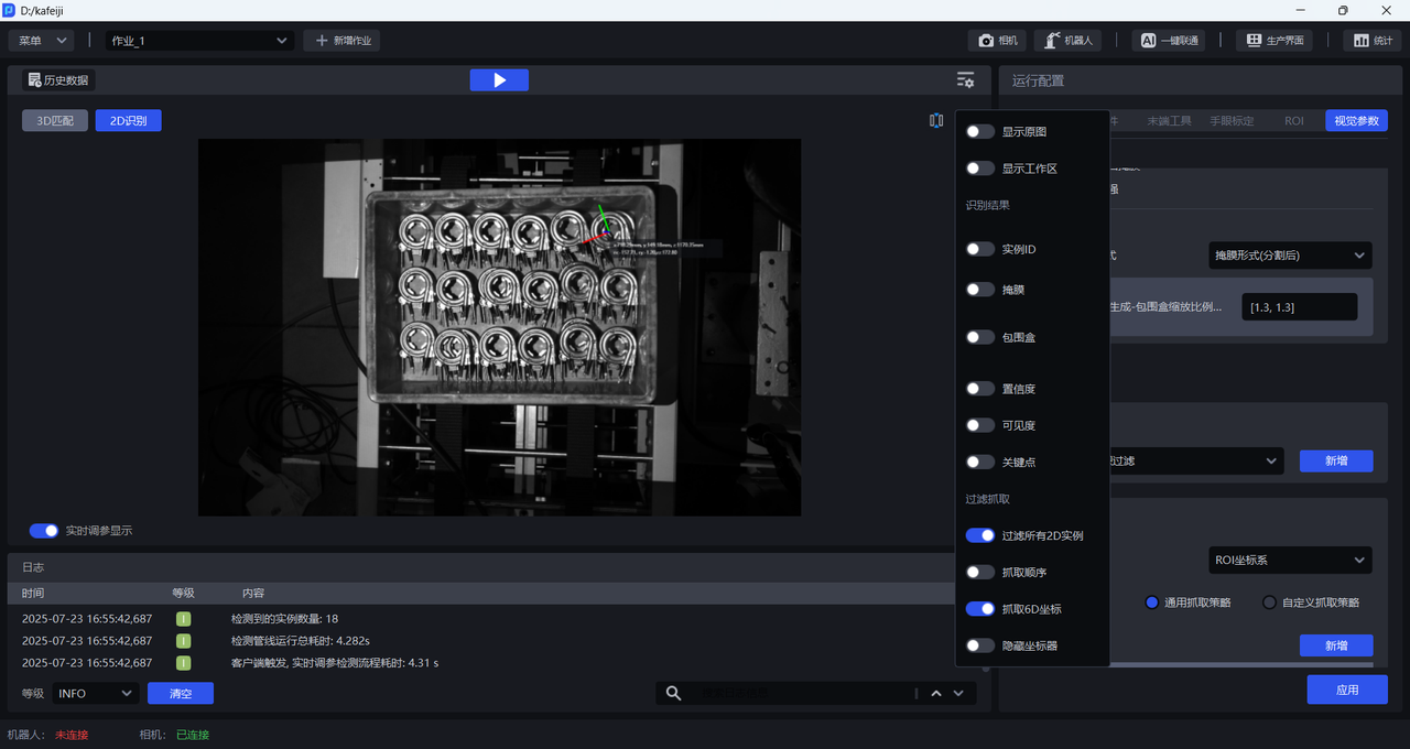
Click the left mouse button on the blank space of the 2D Recognition window to close the setting box, then place the cursor on the 2D Recognition window, slide the mouse wheel upward to enlarge the 2D image and view the 6D coordinates of the Pick Point.
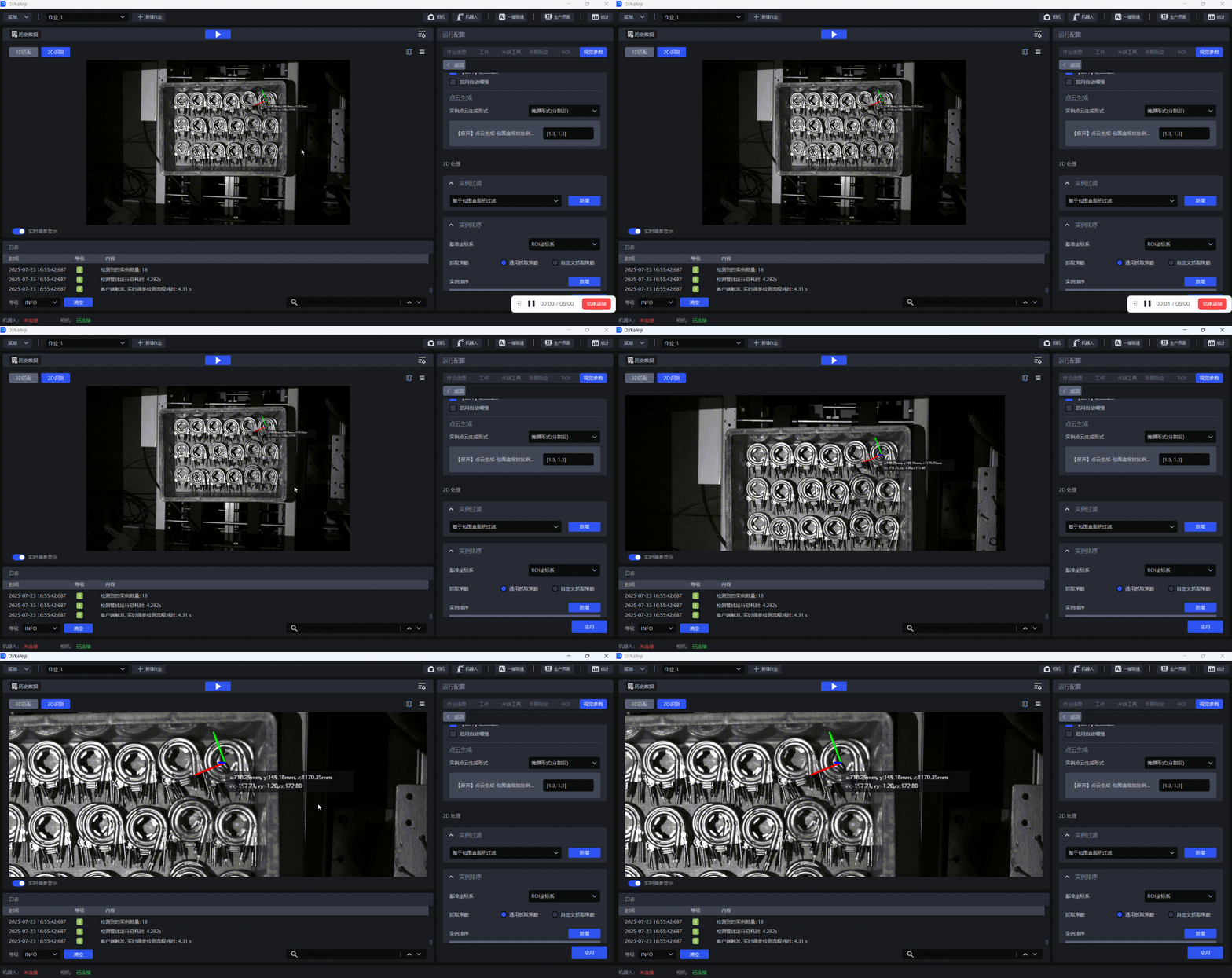
2.1.12 hide coordinate device
Turn on `Hide Coordinates'. When turned on, the Pick Point's coordinates are hidden; when turned off, the Pick Point's coordinates are displayed.
2.2 3D Match
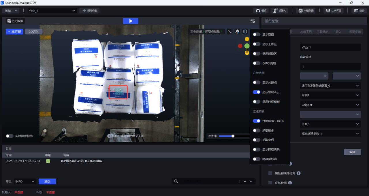
Click the Settings button in the 3D Matching window to select the 3D visual results displayed, as shown in the figure below.
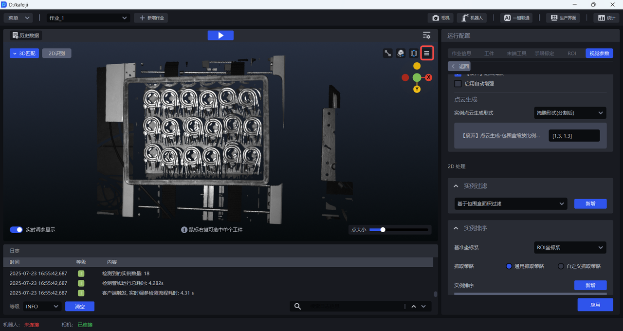
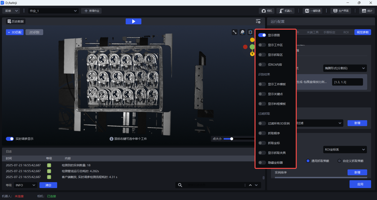
2.2.1 Show original image
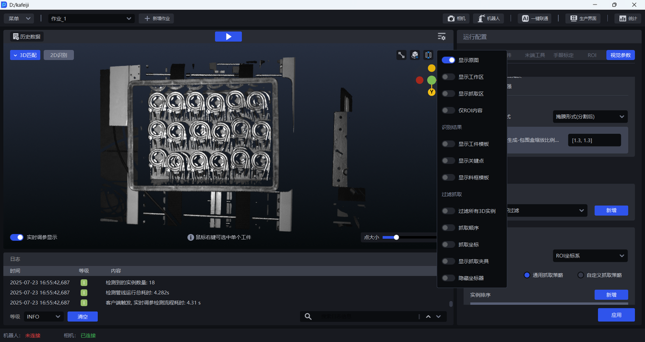
Turn on Show original image. After turning it on, only 3DPoint Cloud will be displayed without any visual results, and other setting items cannot be turned on, as shown in the figure below.
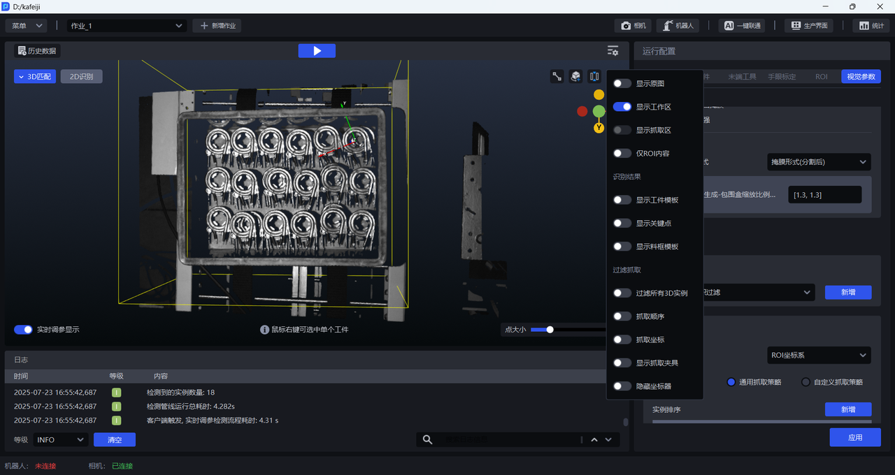
2.2.2 Display work area
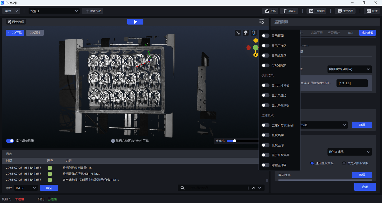
Turn on Show Workspace. After it is turned on, only the ROI 3D workspace will be displayed, and Show Grab Area cannot be turned on, as shown in the figure below.
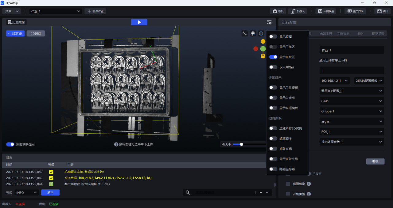
2.2.3 Display grab area
Turn on Show Grab Area. After it is turned on, only the ROI 3D grab area will be displayed, and Show Workspace cannot be turned on, as shown in the figure below.
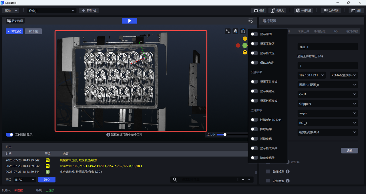
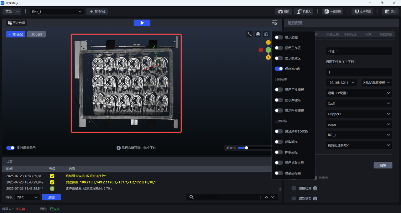
2.2.4 ROI content only
Turn on ROI content only. After turning it on, only the part within the ROI 3D area will be displayed, and the part outside the ROI area will become black, as shown in the figure below.
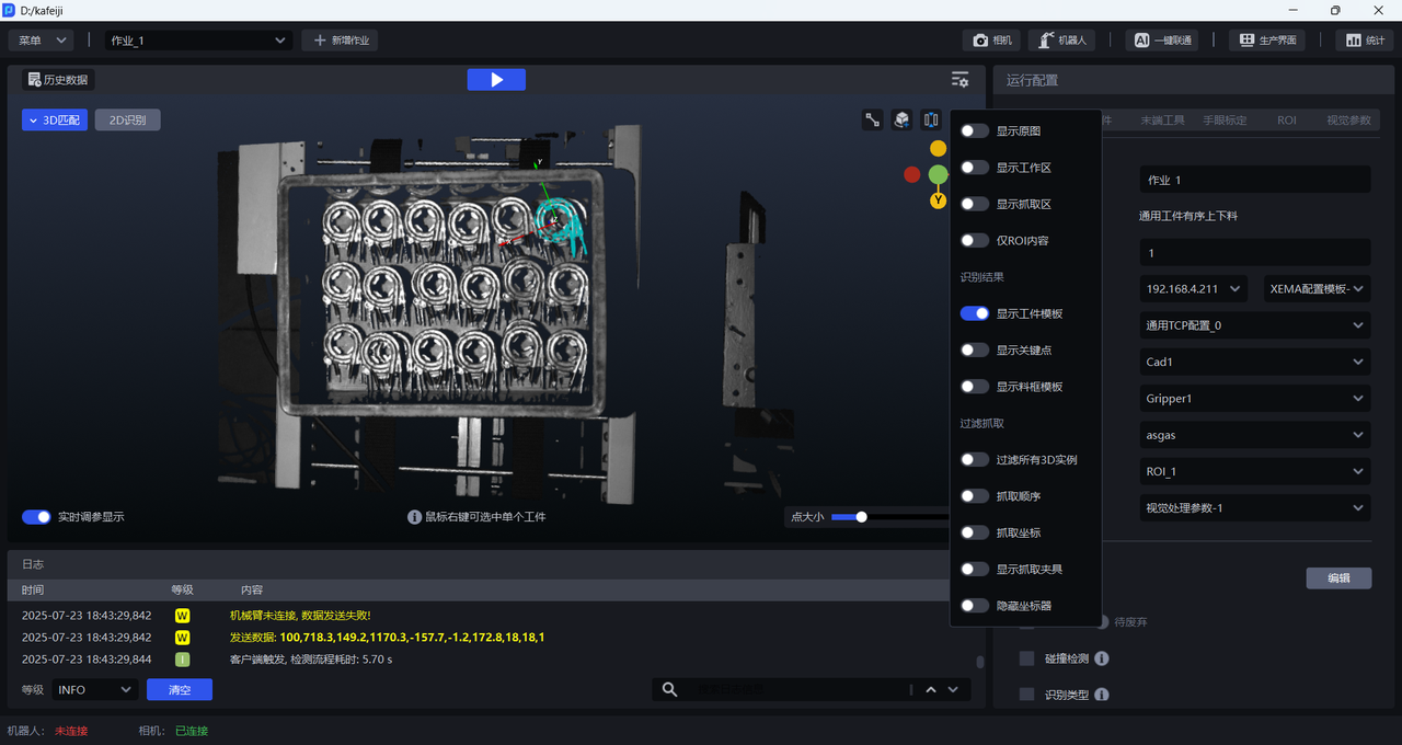
2.2.5 Display Target template
Turn on Show Target Template. After turning it on, the Point Cloud template of the identified Target instance will be displayed, as shown in the figure below.
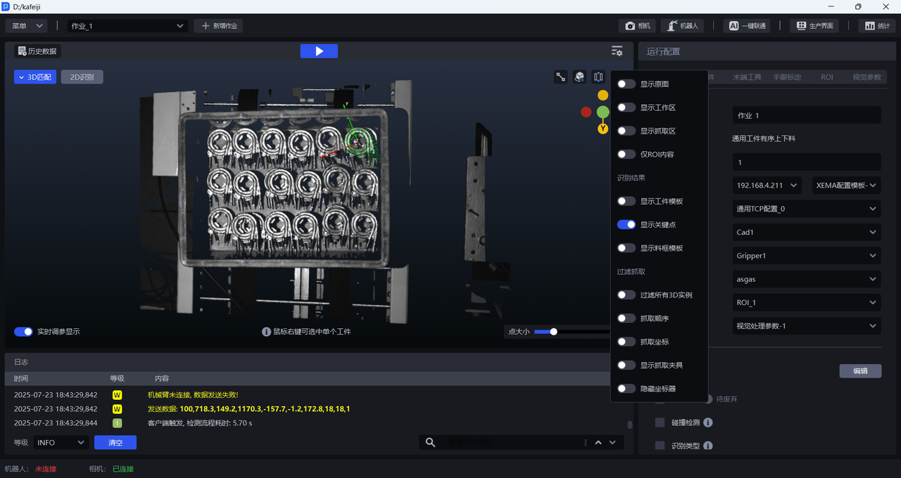
2.2.6 Display key points
Turn on Show Key Points. After turning it on, the key points of the identified Target instance will be displayed, as shown in the figure below.
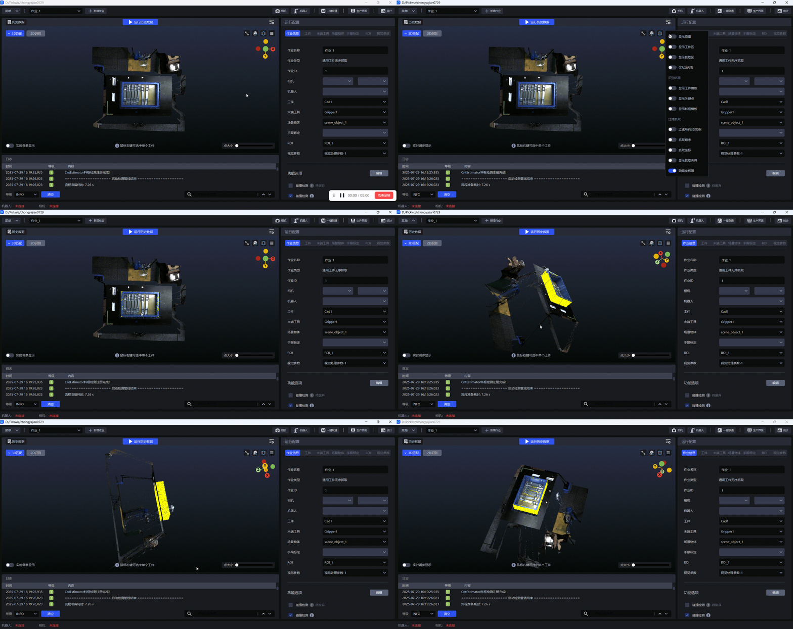
2.2.7 display material frame template
If there is a material frame in the Scene, you need to check the collision detection in the function options to detect whether the End-effector and the material frame will collide during the grabbing process. For details, please refer to [Collision Detection Usage Guide] (碰撞检测使用指南.md). After turning on Show Material Frame Template, you can view the Point Cloud of the material frame template obtained by quadrilateral fitting, as shown in the figure below.
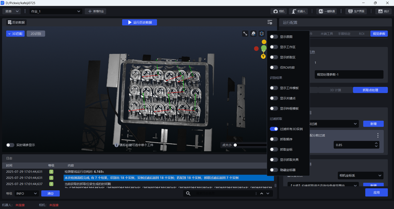
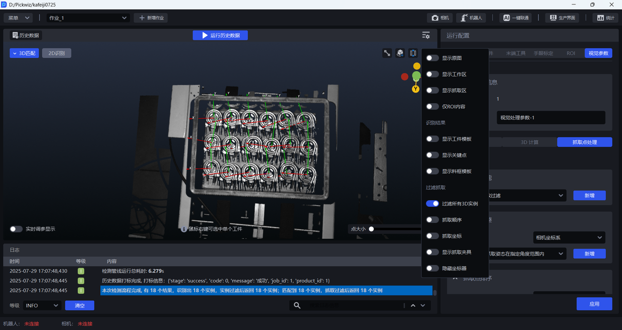
2.2.8 filters all 3D instances
When turned on, the Pick Point output after Pick Point filtering is displayed; when turned off, the Pick Point output by the 3D calculation node is displayed.
As shown in the figure below, the Filtering based on Fine matching score function is added to the Pick Point Filtering node, and the Score Threshold is set to 0.85, so the Pick Point generated by the Target posture with a Fine matching score greater than 0.85 will be output.
When Filter all 3D instances is turned off, the Pick Point output by the 3D calculation node is displayed. As shown in the figure below, 18 Targets all generated Pick Points.
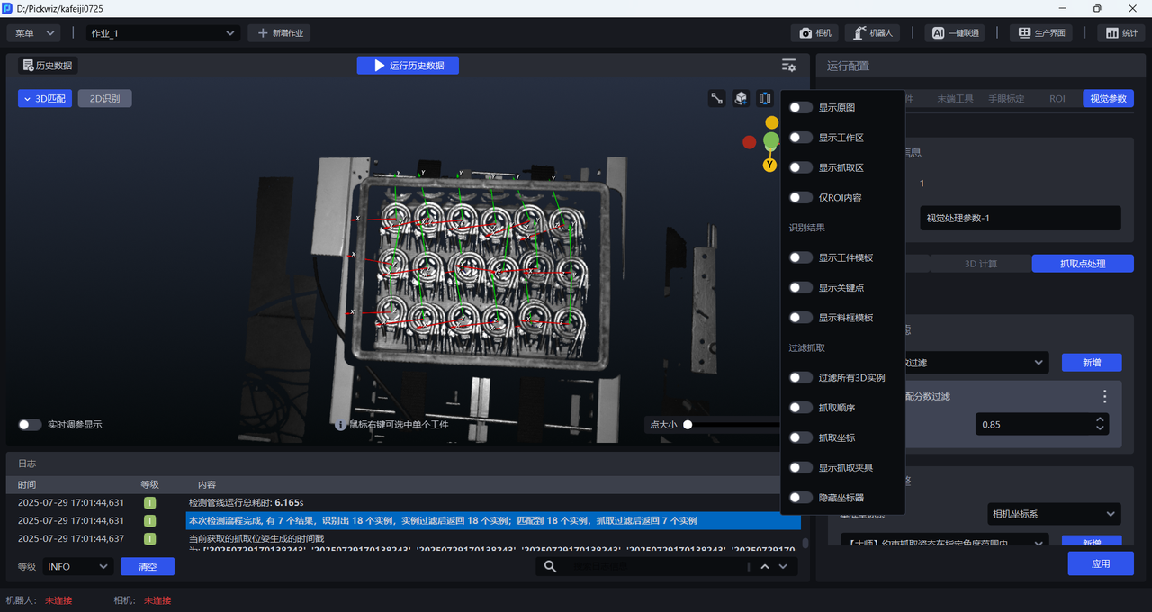
When turned on, the Pick Point output after Pick Point filtering is displayed. As shown in the figure below, Pick Point filters out 11 Pick Points, leaving only 7 Pick Points.
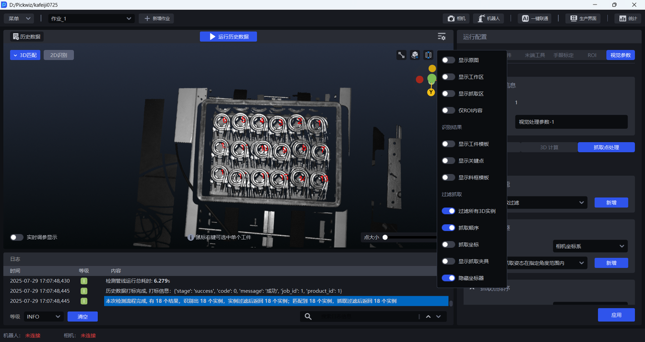
2.2.9 crawling order
After it is turned on, the fetching order of Target is displayed, as shown in the figure below.
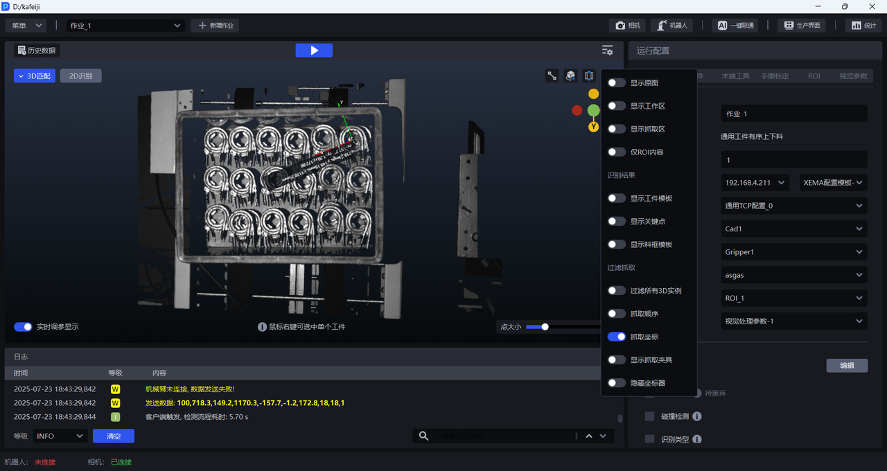
2.2.10 grab coordinates
After it is turned on, the grabbing coordinates of Target are displayed, as shown in the figure below.
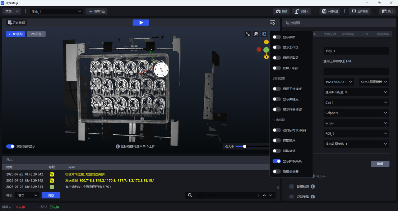
2.2.11 display gripper
After it is turned on, Target's grabbing fixture is displayed, as shown in the figure below.
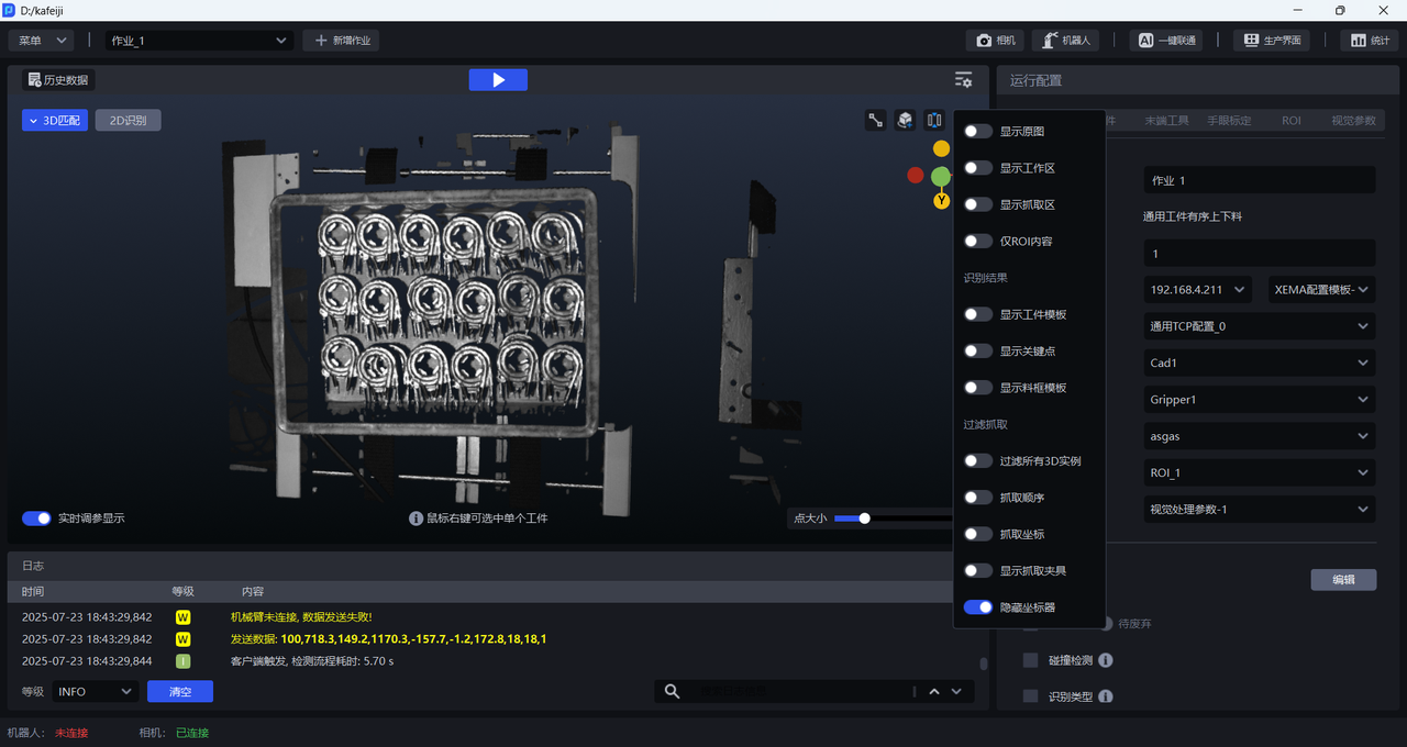
2.2.12 hide coordinate device
When turned on, the coordinate device will be hidden; when turned off, the Pick Point coordinate device will be displayed.
2.2.13 View a single Target
Place the cursor on different Targets to view the visual recognition results of each Target, as shown in the figure below.
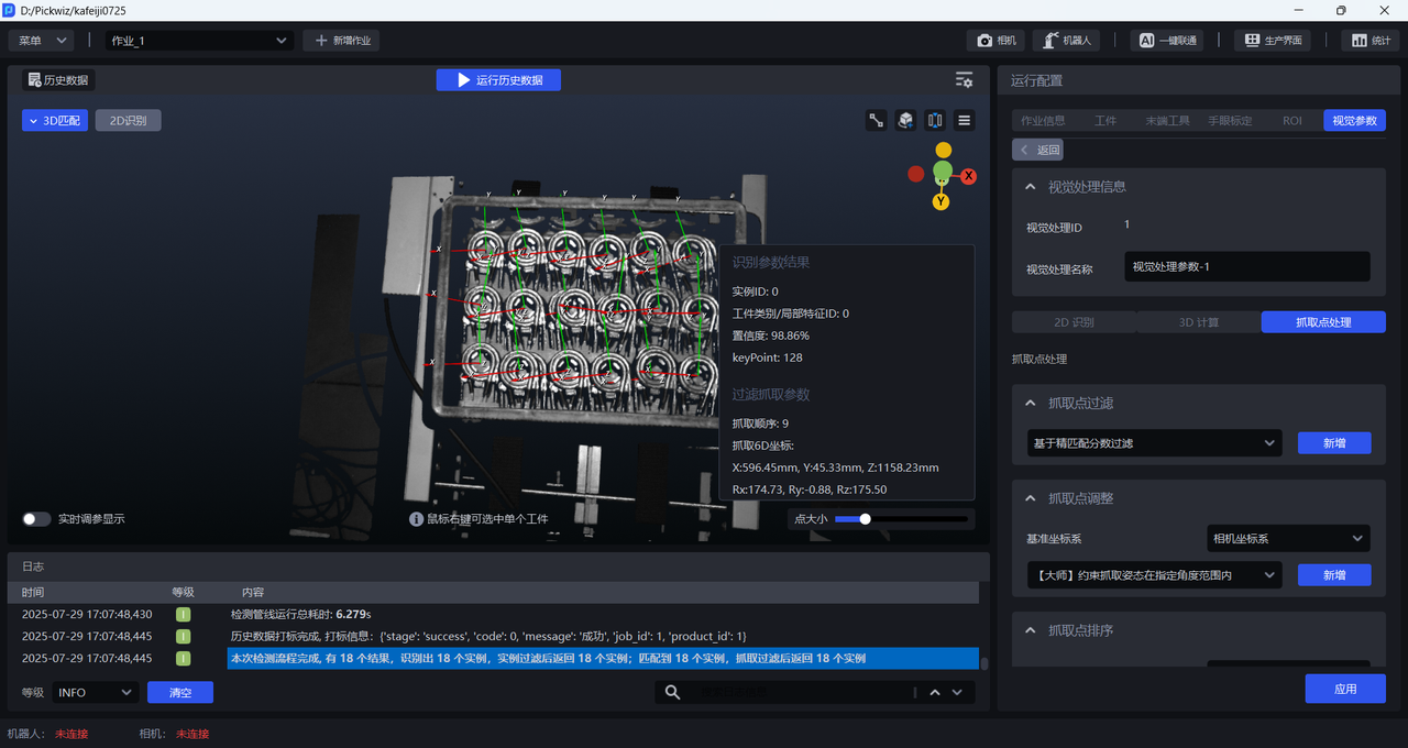
Right-click the mouse to select the Target you want to view, as shown in the figure below.
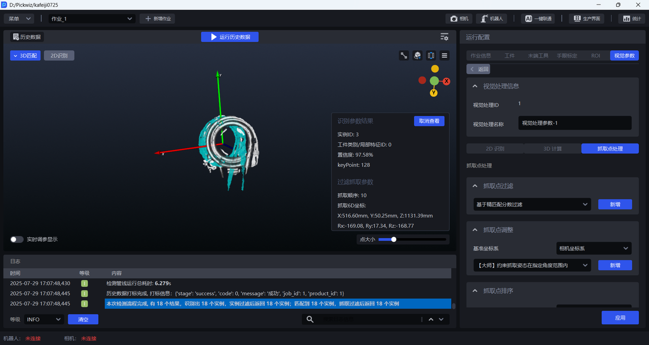
Adjust the point size to adjust the size of the TargetPoint Cloud, as shown in the figure below.
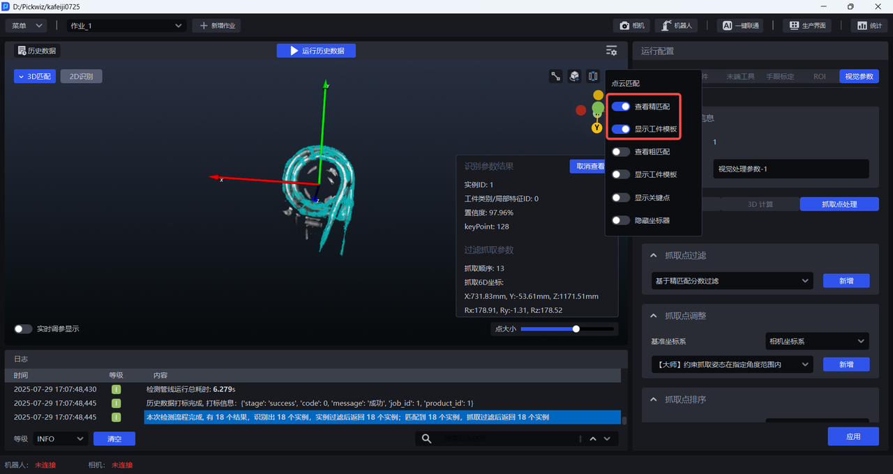
After selecting a single Target, you can view the Target's Point Cloud template and Fine matching results.
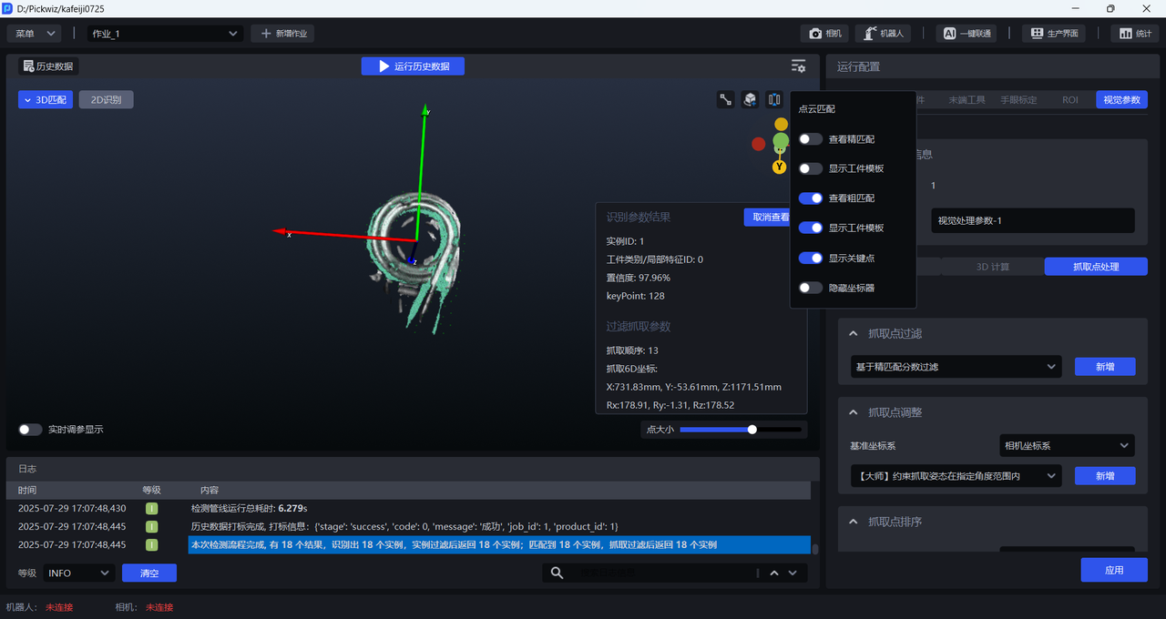
You can also view Target's key points and Coarse Matching results.
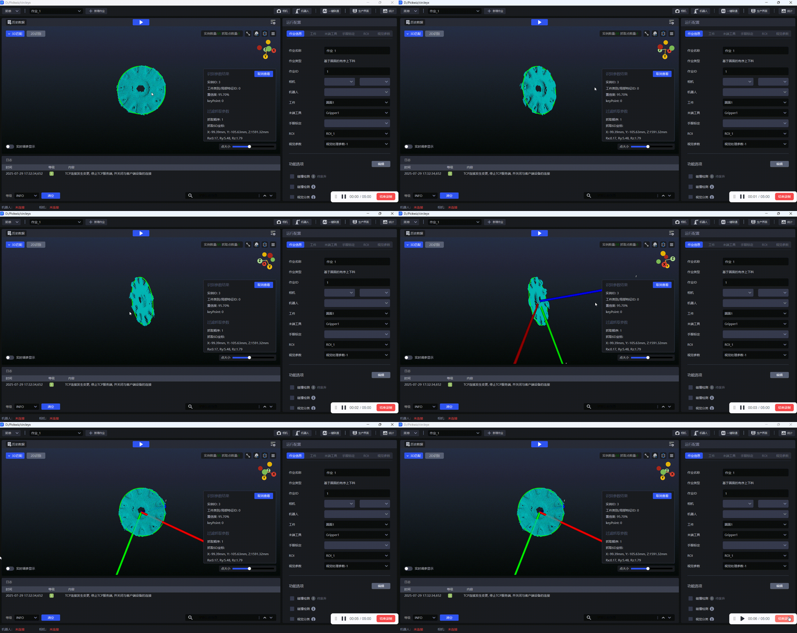
2.2.14 Display fitting circle
For circular targets, turn on Show Fitted Circle to view the fitted circle, as shown in the figure below.
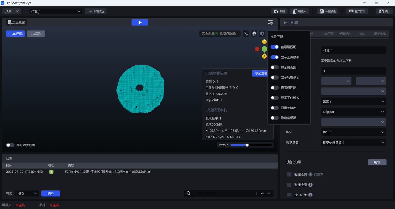
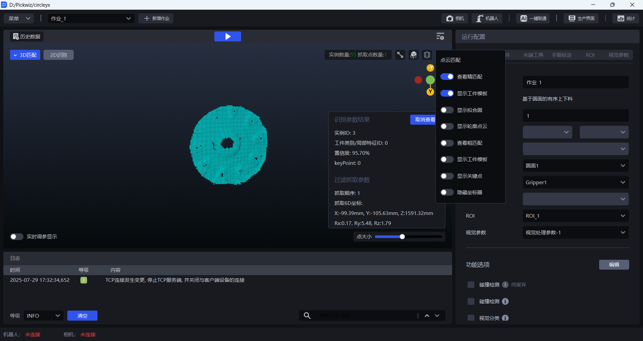
2.2.15 Show Profile Point Cloud
For a round Target, turn on Show Outline Point Cloud to view the outline Point Cloud of the round Target, as shown in the figure below.
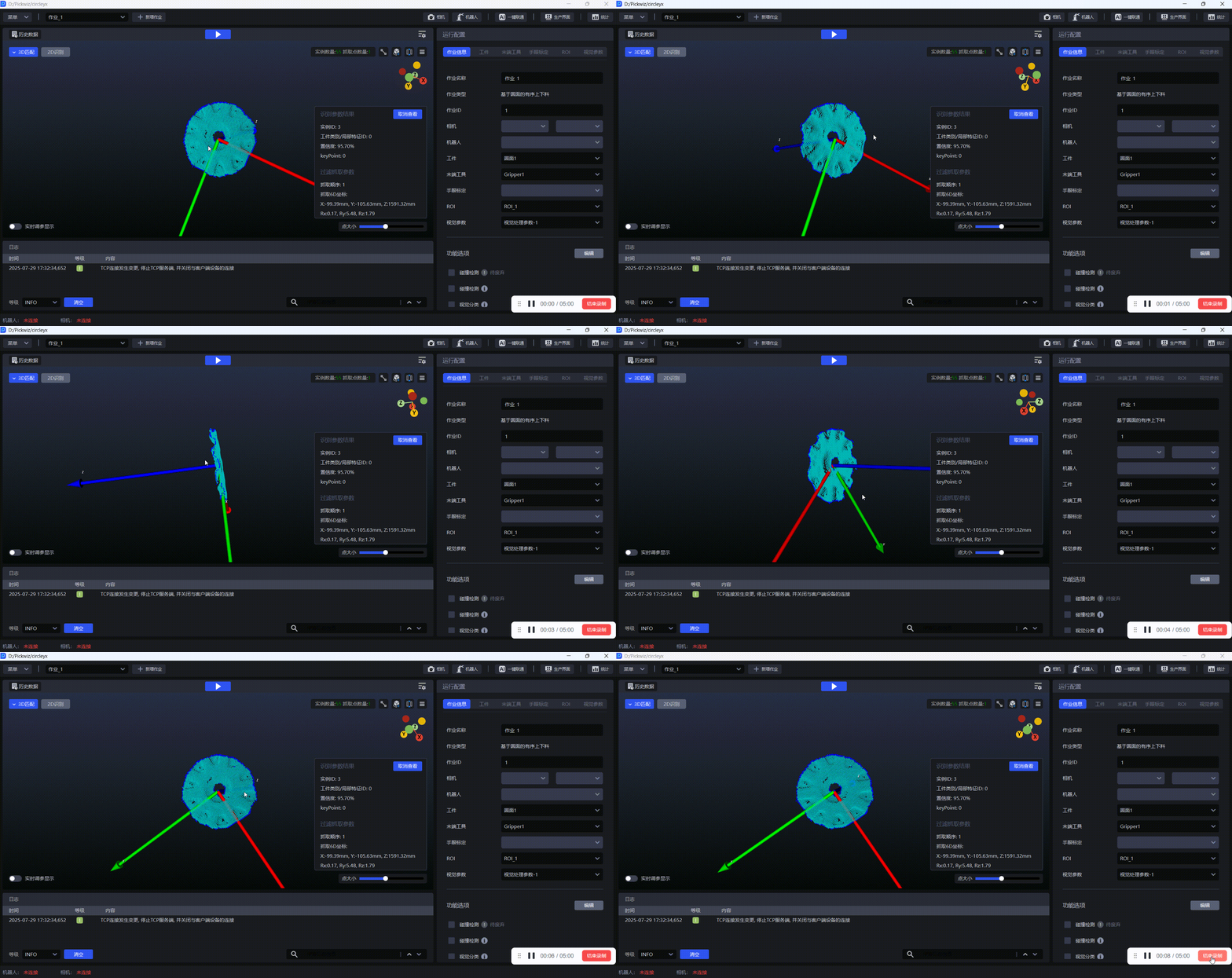
2.2.16 Display Neighborhood Point Cloud
In the depalletizing Scene, the Pick Point is calculated within the neighborhood Point Cloud range. When turned on, the neighborhood Point Cloud within the Pick Point calculation range is displayed.