
Create a Task and Complete Basic Configuration
3. Create a Task and Complete Basic Configuration
3.1 Create a Single-Carton Depalletizing Task
Depending on the current project status, create a new project or add a task to an existing project. The task type cannot be changed after creation, so you must select Depalletizing > Single-Carton Depalletizing when creating it.
3.1.1 Create a Project
When setting up a project for the first time, follow these steps:
- Open PickWiz and select Create Empty Project on the initial page. If another project is already loaded, open the new project page from the menu in the upper-right corner.
- Select Depalletizing > Single-Carton Depalletizing.
- Set the project name and project path. The project name cannot contain Chinese characters or spaces.
- Leave the feature options disabled for now, and use the basic configuration for the first run.
- Click Create.
For the complete procedure, see Create an Empty Project.
3.1.2 Add a Task to an Existing Project
To add a carton depalletizing task to an existing project, follow these steps:
- Click Create Task in the upper-left corner of the main interface.
- Select Depalletizing > Single-Carton Depalletizing.
- Enter a task name that distinguishes the production task or material.
- Click Create.
After creation, PickWiz opens the task’s runtime configuration page. The camera, robot, target, end-effector, eye-hand calibration, ROI, and visual parameters configured later must all be selected in Task Information.
For instructions on creating and switching between multiple tasks, see the Task Operations Guide.
3.1.3 Select Feature Options
For the initial setup, leave the feature options disabled and use the default workflow to identify a set of cartons and calculate Pick Points. After validating the basic workflow, enable features according to the needs of the site:
- To handle interlayer separators or pallets, enable the corresponding detection features.
- To distinguish carton textures, orientations, or categories, enable visual classification or Type Identification.
- To filter out pick poses with a collision risk, enable collision detection.
After feature options are enabled, PickWiz adds the corresponding Target, Scene Object, or visual parameter settings. Check the runtime configuration and visual results again.
3.2 Complete Basic Configuration
After creating the single-carton depalletizing task, configure the camera, robot, Target, end-effector, eye-hand calibration, and ROI in that order, then select the corresponding configurations in Task Information. This chapter covers only the points that require particular attention for carton depalletizing.
3.2.1 Select Camera and Robot Configurations
- In Task Information, select a camera configuration that has been connected and tuned.
- Capture an image and confirm that the 2D image of the top layer of cartons is complete. Check the 3D Point Cloud for missing areas, collapsed areas, or obvious noise.
- Select a robot configuration for which communication has been established.
- Verify the number of robot axes, rotation representation, and coordinate system type. Incorrect settings will cause the output pose to differ from the pose used by the robot.
Depalletizing scenes typically use a KINGFISHER stereo camera. If the camera cannot connect or the Point Cloud is abnormal, see the Camera Connection and Tuning Guide and the KINGFISHER Series Camera User Manual.
Tune carton exposure and the Point Cloud in the following order:
- Use + to create an editable configuration from a similar default camera template, and save the initial parameters. Keep one set of cartons as a comparison sample, with the lighting and viewing angle unchanged.
- Enable the overexposure display and inspect the left and right camera images separately. Focus on the boundaries between cartons, surface textures, and reflections from tape. Do not judge exposure by the overall brightness of the background.
- With fixed exposure, change only the exposure value before each new capture: increase it appropriately if underexposure makes the boundaries indistinguishable; decrease it if carton surfaces turn white or the bright areas on the tape expand. Then check the 3D Point Cloud again.
- With automatic exposure, follow the camera guide to place the exposure focus area on a representative carton surface so that large background areas do not dominate exposure. The exposure focus area is different from the ROI used later for identification.
- If a single exposure cannot accommodate both light and dark cartons, evaluate high dynamic range exposure according to the camera’s capabilities. Compare Point Cloud completeness on carton surfaces, texture, and capture time. Do not copy exposure multipliers from another site without evaluation.
- In 3D, check whether carton surfaces are continuous and whether points are missing or stray points appear near the tape. Adjust denoising as needed. Do not remove carton edges merely to obtain a smooth image.
- Capture images again for the top layer, bottom layer, partially emptied stack, and different surface conditions. With automatic exposure, also check whether exposure makes carton surfaces overexposed after the background becomes visible.
- Save and associate the camera configuration. Record carton surface texture, missing Point Cloud areas, and capture time before and after tuning. After completing the subsequent visual configuration, retest instance boundaries, top-layer selection, and Pick Point stability.
The following calibration board exposure examples are reused from the camera guide to help distinguish underexposure, appropriate exposure, and overexposure. They are not images measured in a carton depalletizing scene, nor are they recommended carton exposure settings. Observe the white areas and black details; the background does not need to be equally bright.
| Underexposed | Properly exposed | Overexposed |
|---|---|---|
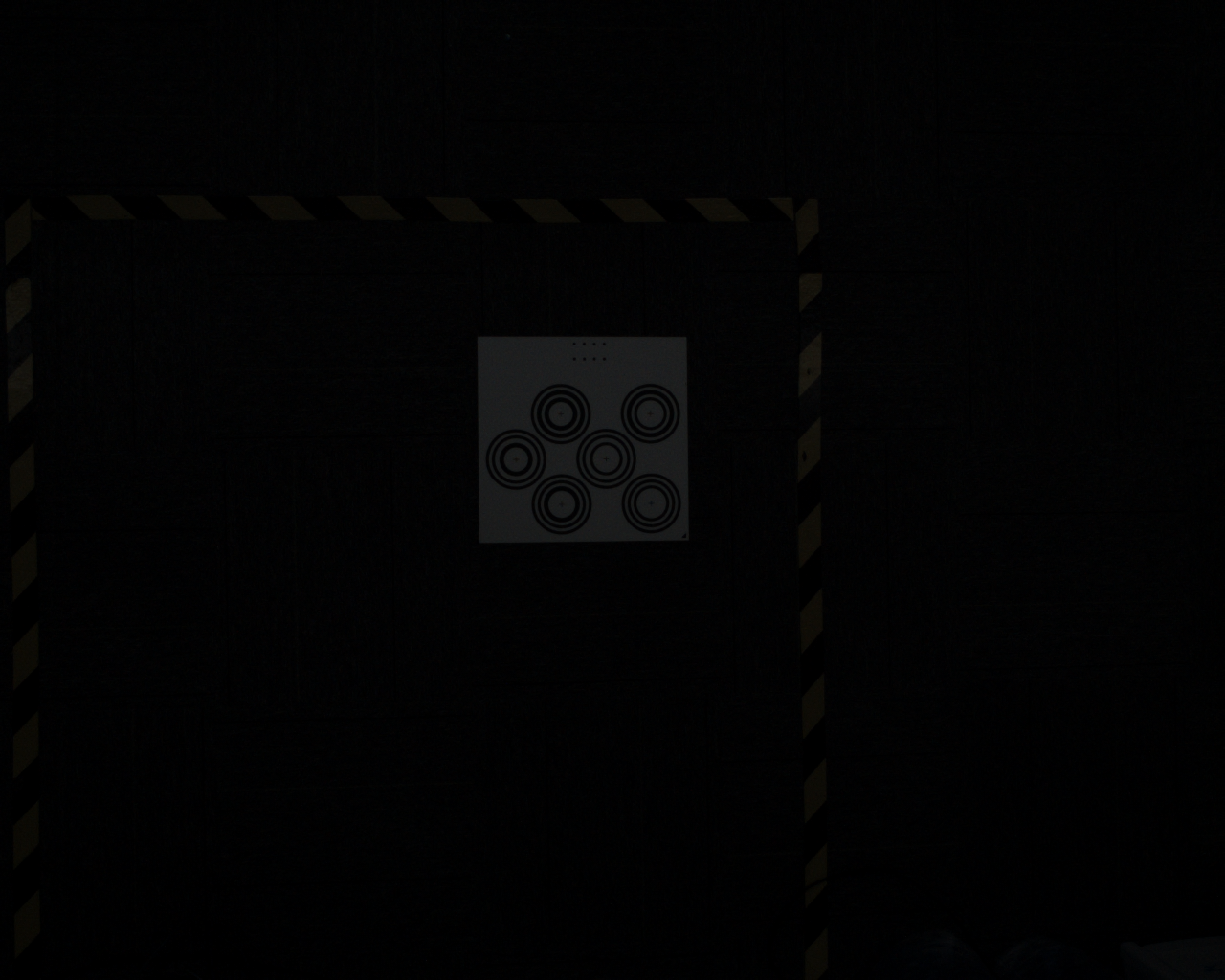 | 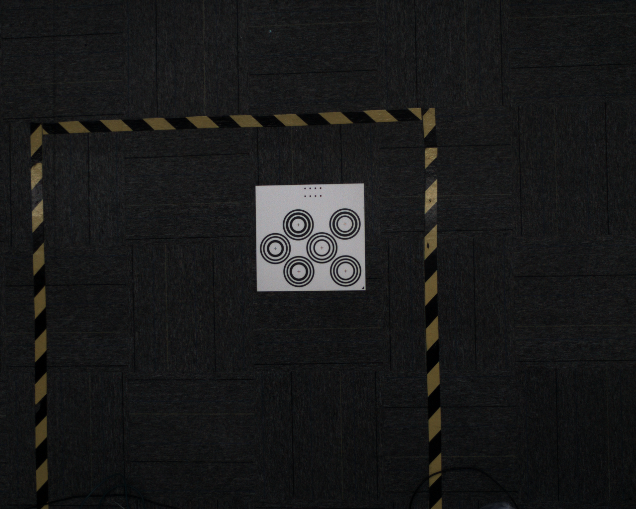 | 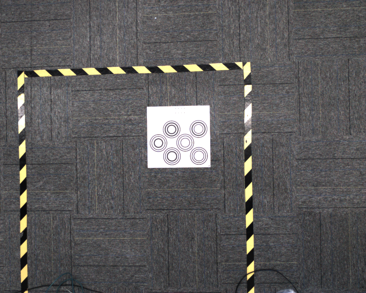 |
For the carton scene, consider exposure acceptable when the boundaries between cartons are distinguishable, the Point Cloud on valid carton surfaces is complete, and repeated captures are stable. Proper exposure in a single 2D image does not replace the subsequent 3D and Pick Point validation.
3.2.2 Configure the Carton Target and End-effector
- Add a carton Target on the Target page. Loading the Visual Model for the first time may take a while.
- Use the default general carton model for the first test. Do not train a new model yet.
- You can retain the default carton length, width, and height. If you need to filter instances by a size range, enter values based on measured dimensions.
- The default Pick Point is Carton Center. Change it to the corresponding corner only if the process explicitly requires picking from a carton corner.
- Add and select an end-effector. If collision detection is disabled, you do not need to import a gripper model.
- If you use a gripper model for collision detection, ensure that the model origin’s position and orientation match the robot TCP.
For detailed configuration instructions, see the Target Configuration Guide and End-effector Configuration Guide.
3.2.3 Select and Check Eye-hand Calibration
- Complete the appropriate eye-hand calibration based on how the camera is mounted and the number of robot axes.
- Before calibration, verify the number of robot axes, rotation representation, and coordinate system type.
- After calibration, perform touch-point verification and record the actual positioning error.
- In Task Information, select a calibration result that has passed inspection.
For selecting a calibration method, see the Eye-hand Calibration Procedure. For checking accuracy, see Checking and Analyzing Calibration Results.
3.2.4 Create an ROI and Load Scene Data
- On the ROI page, click Add ROI and set a name and unique ID.
- Load Scene data according to the debugging method:
- If the camera is connected, use Capture Image to obtain an image and Point Cloud of the current site.
- For offline debugging, import the 2D image and 3D Point Cloud from the same historical data record.
- When using a KINGFISHER stereo camera, set ROI 2D in the left camera image and confirm that the automatically synchronized ROI in the right camera image also covers the target area.
- Confirm that the 2D image and 3D Point Cloud come from the same capture to avoid region mismatches caused by changes in the Scene.
Point Clouds in Historical Data
Historical data generated in Ultra-Fast Mode may not contain a saved PLY Point Cloud. If this occurs, generate Point Cloud data in the historical data first, then return to the ROI page to import it.
3.2.5 Set ROI 2D for Carton Depalletizing
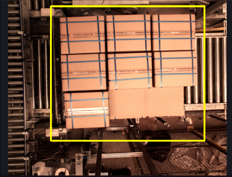
Draw ROI 2D based on the image area occupied by the top layer of cartons:
- Include every carton that may appear completely within the workspace.
- Leave an appropriate margin for tilted cartons, pallet positioning errors, and incoming material offsets. Do not place the border tightly against the cartons.
- Make the ROI as small as possible while still covering the incoming material range. This reduces interference from the conveyor, guardrails, and other surrounding areas during instance identification.
- When using a stereo camera, check that the cartons are within the valid area in both the left and right camera images.
3.2.6 Set ROI 3D for Carton Depalletizing
Adjust ROI 3D according to the actual spatial extent of the cartons and pallet:
- Adjust the orientation of ROI 3D so that the positive Z direction points upward. If the incoming material is tilted as a whole, make the Z axis perpendicular to the carton stacking surface.
- Use the pallet, bin, or positioning stops as references when adjusting the ROI’s orientation and boundaries. Align it as closely as possible with the incoming material area.
- ROI 3D should cover the full incoming material range, from the top layer of cartons to the bottom layer, with a margin for actual position tolerances.
- If the pallet does not need to be identified, set the bottom face of ROI 3D above it to reduce interference from the pallet’s Point Cloud.
- Exclude fixed structures such as guardrails, supports, and conveyors. Do not make ROI 3D excessively large simply to leave a margin.
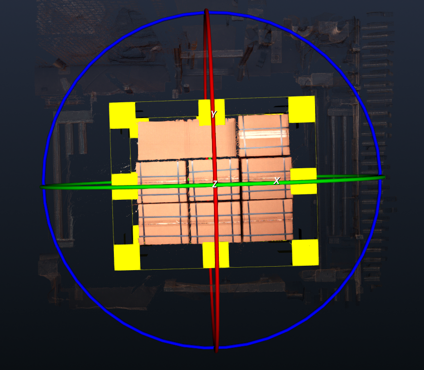
ROI Safety Boundary
Pick Points output by the vision system are usually constrained by the ROI 3D range. If the ROI includes guardrails, supports, or other areas that must not be picked, misidentified results may enter the robot’s workspace. Before saving, check the ROI 3D boundaries from multiple viewpoints.
For complete instructions on using the ROI interface, see the ROI Configuration Guide.
3.2.7 Save and Select Runtime Configurations
- Save the ROI configuration.
- Return to Task Information and select the camera, robot, Target, end-effector, eye-hand calibration, and ROI in that order.
- Retain the default visual parameters generated automatically for the new task. Adjust them in the next chapter based on the results of the first run.
- Check that all required configurations have been selected, then save the task configuration.