
Hardware Installation Guide
The 3D vision guidance kit consists of a robot, a 3D camera, and an industrial PC. After completing hardware installation, network connections, and communication tests, proceed with camera parameter configuration and eye-hand calibration.
1 Hardware Components
The kit includes the following hardware:
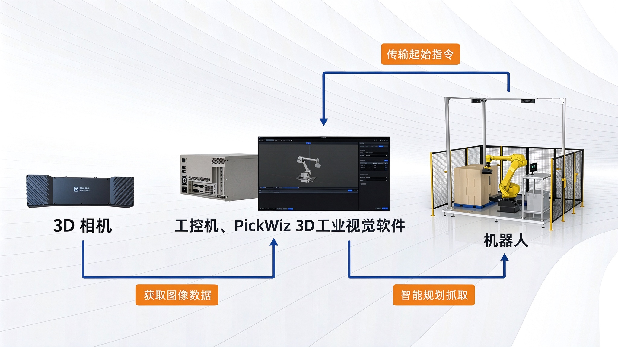
- Robot: Includes the robot body, controller cabinet, and teach pendant.
- 3D camera: Captures images and pose information of the target object.
- Industrial PC: Runs PickWiz and the vision algorithms, and communicates with the camera and robot.
2 Camera Installation and Connection
2.1 Select the Camera Installation Manual
First confirm the camera series. Then follow the corresponding manual to secure the camera bracket, connect the Ethernet cable and power supply, and check the connection status.
| Camera series | Hardware installation manual | Covered topics |
|---|---|---|
| XEMA | XEMA Series Camera Hardware Installation Manual | Bracket installation, aviation connector or RJ45 Ethernet connection, DC 24 V power supply |
| FINCH | FINCH Series Camera Hardware Installation Manual | Bracket installation, aviation connector Ethernet connection, DC 24 V power supply |
| KINGFISHER | KINGFISHER Series Camera Hardware Installation Manual | Bracket installation, single-port or dual-port Ethernet connection, PoE power supply |
2.2 Connect the Camera
- Follow the corresponding camera installation manual to mount the camera on a bracket or at the end of the robot. Confirm that it is securely mounted and that its field of view covers the work area.
- Connect the camera Ethernet cable as instructed in the manual. The camera can connect directly to the industrial PC or through a switch on the same gigabit network.
- Connect the camera power supply or PoE power as instructed in the manual. Before powering on, confirm that the power connection, Ethernet cable, and connectors are secure and that robot movement will not pull on the cables.
- Check the camera indicator lights or switch port status to confirm that the camera has started normally and is connected to the network.
2.3 Connect to PickWiz
After completing the camera hardware connections, refer to the Camera Connection and Parameter Tuning Guide to add the camera in PickWiz and configure its parameters.
3 Connect the Robot, Controller Cabinet, and Industrial PC
3.1 Connect the Hardware
- Connect the robot body cable to the robot controller cabinet. Align the connector before inserting it slowly.
- Connect the teach pendant to the robot controller cabinet and place it where it is easy to operate.
- Connect the robot controller cabinet and industrial PC with an Ethernet cable. A switch may be used according to the site network plan, but the robot, camera, and industrial PC must each meet their network topology requirements.
- Connect power to the robot controller cabinet and start the teach pendant so the robot is ready to communicate.
3.2 Check the Robot System Environment
Confirm that the following items meet the robot manufacturer’s requirements and the site network configuration:
- The teach pendant is connected and operating normally.
- The Ethernet port on the robot controller cabinet and the Ethernet cable on the industrial PC are connected properly.
- The robot controller cabinet and industrial PC are on network segments that can communicate with each other.
- The TCP network communication package is enabled on the robot.
- The robot system version meets the requirements of the current communication program.
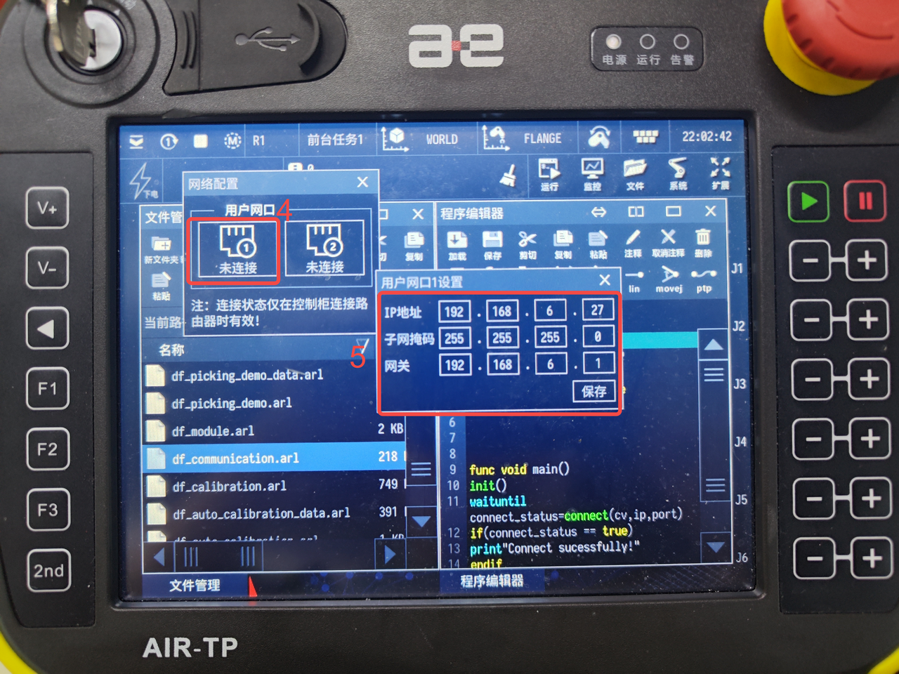
3.3 Connect to PickWiz
Refer to the Robot Configuration Guide to add the robot in PickWiz and configure its communication parameters.
3.4 Test Robot Communication
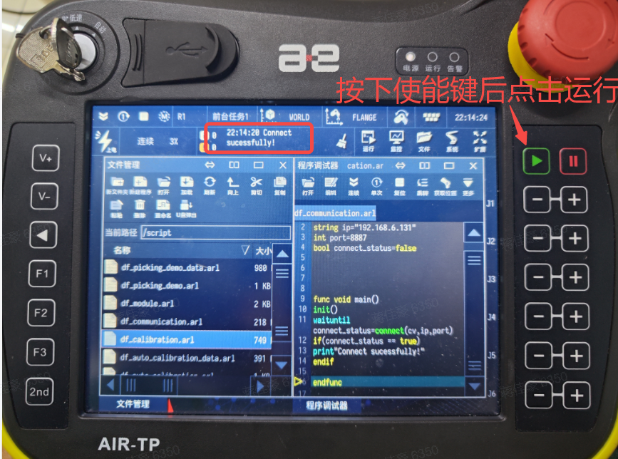
- On the teach pendant, switch to the communication test program and select
df_communication.arl. - Set the IP address and port in the global variables at the top of the program to match the industrial PC.
- Run the communication test program step by step or continuously.
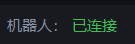
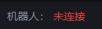
- Observe the connection status in PickWiz: when the program reaches the
connectfunction, the robot icon should show connected; after the program reaches the step that closes the connection, the icon should show disconnected. - Confirm that the
Connect successfully!message appears on the teach pendant.
4 Acceptance Criteria and Next Steps
The hardware setup is complete when all the following conditions are met:
- The camera bracket, Ethernet cable, and power supply have been connected according to the corresponding hardware installation manual.
- The network connection between the camera and industrial PC is working, and PickWiz can detect the camera.
- The robot controller cabinet, teach pendant, and industrial PC are connected properly, and the network configuration meets the communication requirements.
- The robot connection status in PickWiz is normal, and the teach pendant displays
Connect successfully!.
After confirming these conditions, proceed to Pre-Calibration Checks for Eye-Hand Calibration to continue preparing for eye-hand calibration.