
Recognition and Picking FAQ
1. Stereo Cameras
1.1 Image Acquisition Takes Too Long with Auto Exposure
Issue: With a stereo camera in auto exposure or exposure-ratio-based HDR mode, how can the image acquisition cycle time be improved further? 【≥1.7.1】
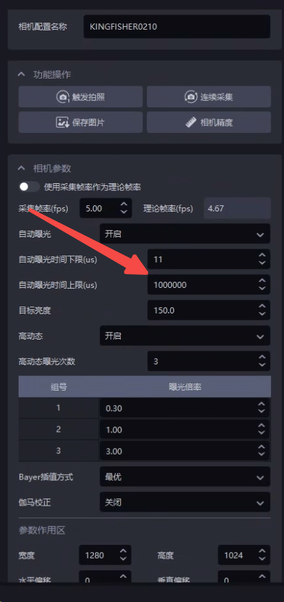
Solution: Set an upper limit for auto exposure time to control the maximum exposure time of each image. We recommend a value above 200000μs (200ms). A lower value will not increase the frame rate, which is capped at 5 fps, and will reduce image quality. At 200000μs, the acquisition cycle time is as short as it can be. The algorithm automatically compensates for brightness through gain, maintaining the overall result while reducing acquisition time. In HDR mode, this parameter also limits the maximum exposure time and thus reduces the total HDR acquisition time.
1.2 Application Crashes When Taking a Photo
Issue: The application crashes when taking a photo with a stereo camera.
Possible cause: The stereo camera is not using a gigabit network connection.
Solution: A stereo camera requires a gigabit network connection. Check whether the network cable supports gigabit speeds and replace it if necessary.
1.3 Image Acquisition Failure
Issue: The stereo camera reports an image acquisition failure.
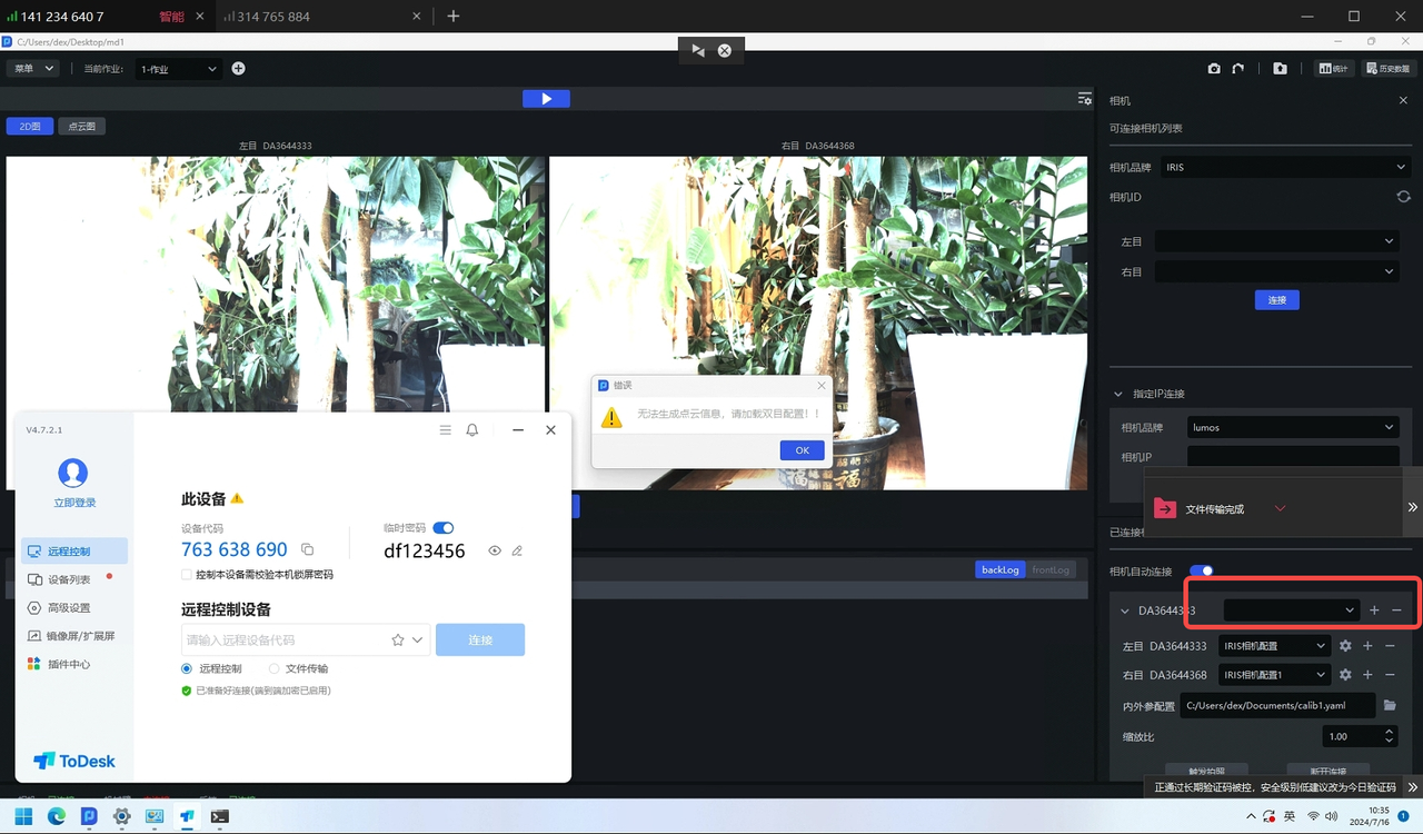
Solution: Create a new stereo camera configuration, then acquire the image again.
1.4 Image Acquisition Failure
Issue: The stereo camera reports an image acquisition failure.
Possible cause: Severe packet loss.
Solution:
Connect to the stereo camera using MVS and start acquisition. Check whether a pop-up warns of severe packet loss.
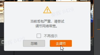
If it does,
Ensure the camera switch is dedicated to cameras and the network is stable. Set the camera exposure to 5000 to facilitate the subsequent bandwidth test.
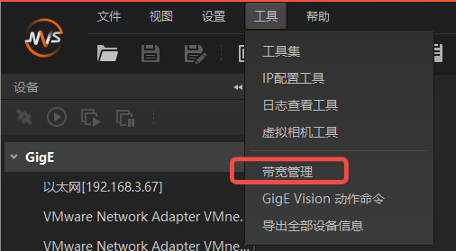
Open the bandwidth management tool and connect to the camera you want to use.
Determine the maximum network bandwidth: move the camera bandwidth slider to its maximum and note the value, such as 964M. Testing shows that some bandwidth should be reserved (provisionally 64M), leaving 900M of usable bandwidth.
Allocate bandwidth according to the number of devices. For example, if 4 cameras must operate simultaneously, set each camera’s bandwidth to 900/4=225M.
Click Start Analysis. If the transmitted-data bandwidth does not reach the allocated limit or the camera loses packets, continue investigating the cause.
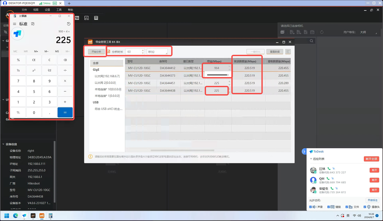
1.5 Abnormal Point Cloud
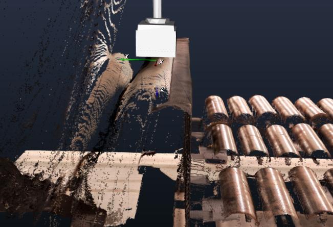
Issue: The point cloud captured by a stereo camera appears collapsed or distorted.
Possible causes: The 2D image is overexposed or too dark; the target’s long axis is not perpendicular to the image; or a visual blind spot is present.
Solution:
- First, check whether the 2D image is overexposed or too dark. If so, adjust the exposure first.
| Status | 2D Image | Point Cloud | Notes | Action |
|---|---|---|---|---|
| Before exposure adjustment (too dark) | 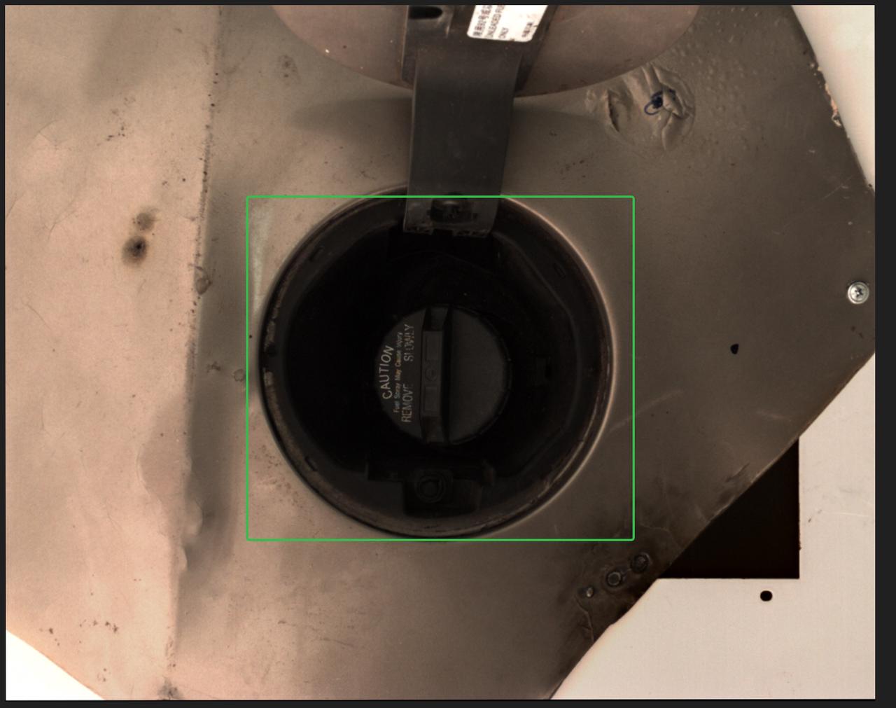 | 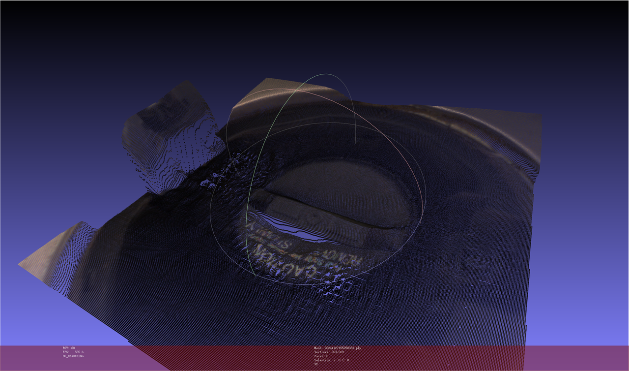 | Collapsed | Add lighting so the target object’s surface is clearly visible |
| After exposure adjustment | 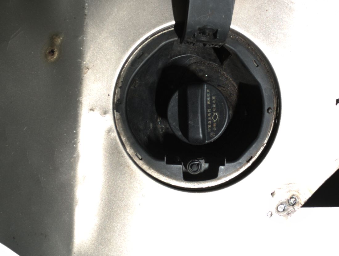 | 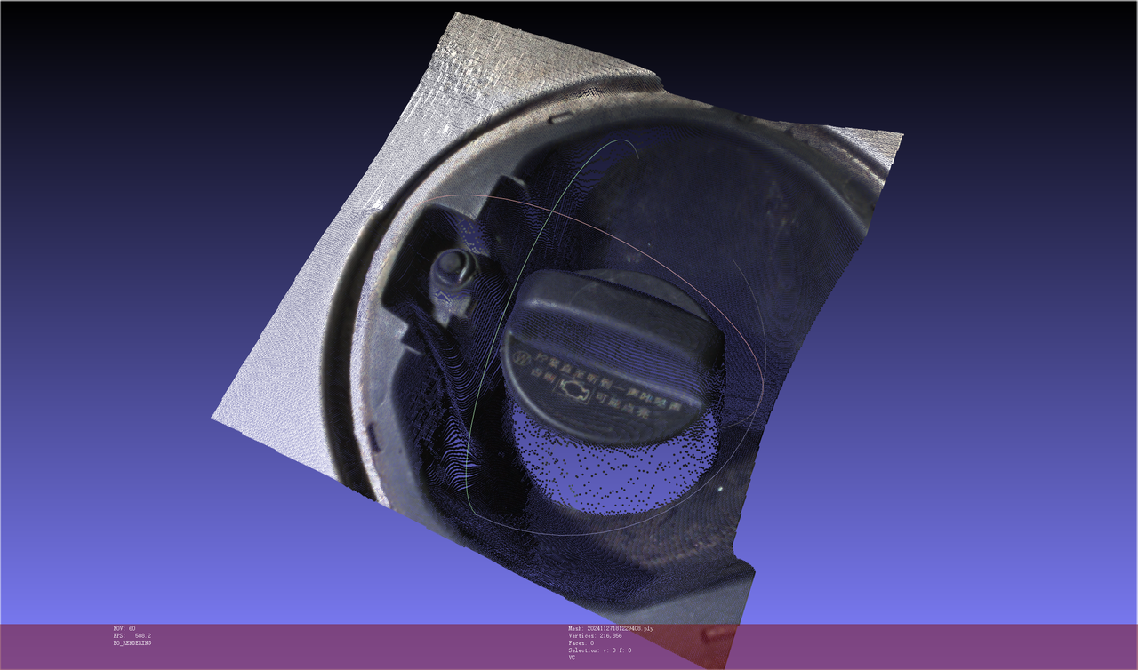 | Normal | / |
| Status | Point Cloud | Notes | Action |
|---|---|---|---|
| Before exposure adjustment (too dark) | 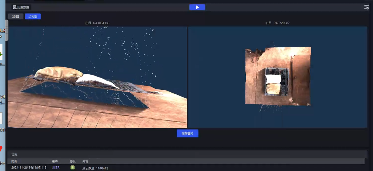 | Collapsed | 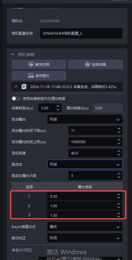 |
| After exposure adjustment | 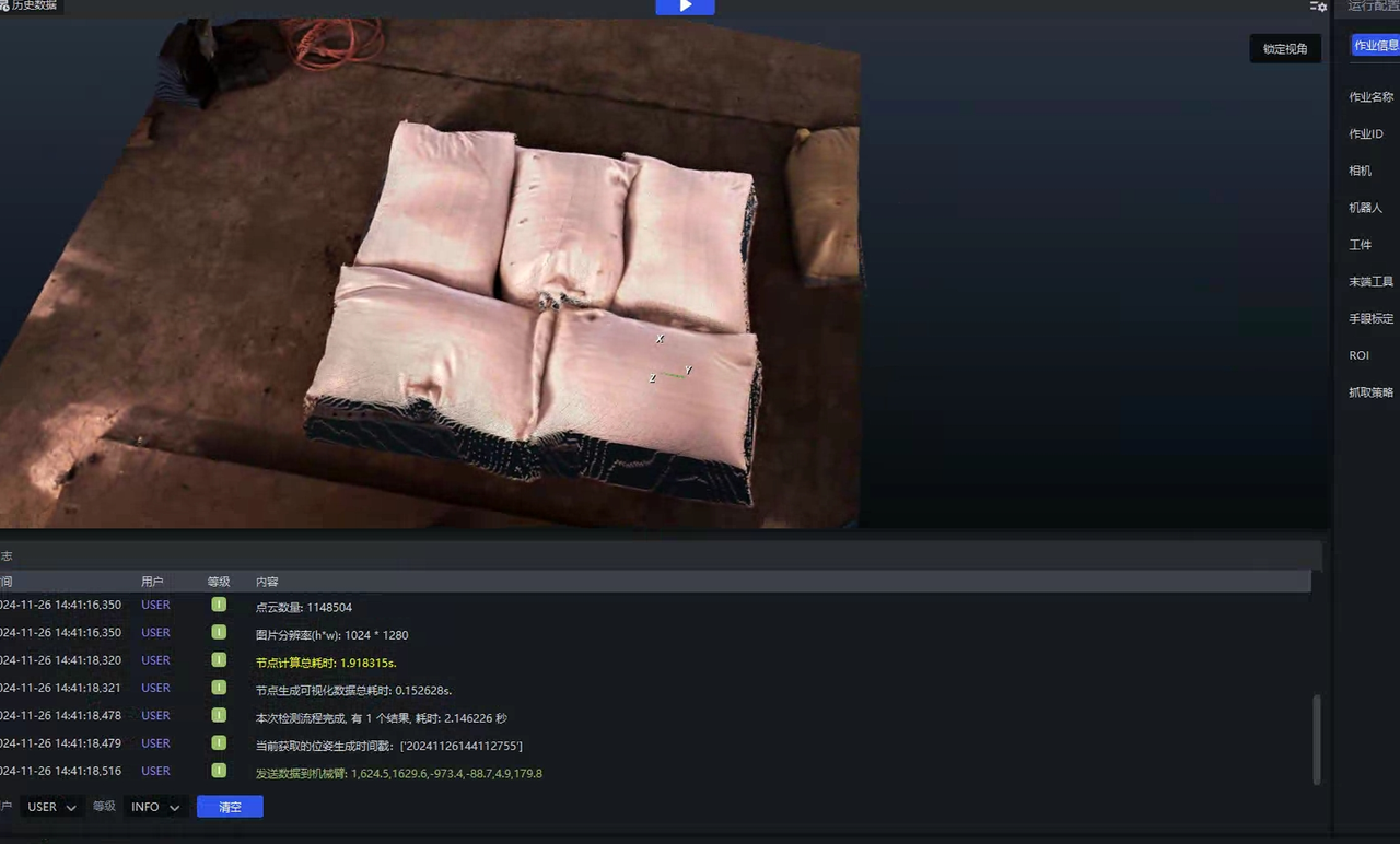 | Normal | / |
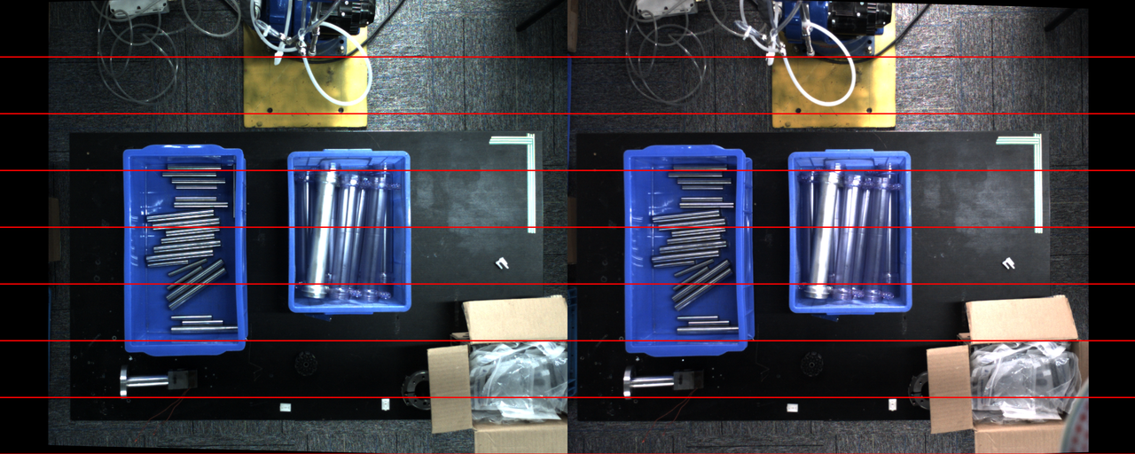
Check whether the target’s long axis is perpendicular to the image. Because this relates to the stereo camera’s corresponding-points principle, we recommend rotating the camera’s mounting angle by 90 degrees, as shown below.

If an object lies in a “visual blind spot” between the left and right images, the model cannot predict the point cloud correctly, resulting in distortion or collapse.
What does a visual blind spot mean? Can only one camera see the object? The left camera can see an area that the right camera cannot, or vice versa. Why can’t the model resolve this? The usual approach is shadow mode, but this area is occluded and therefore will not be included in shadow-mode learning. Shadow mode cannot help in this case.
Example Image 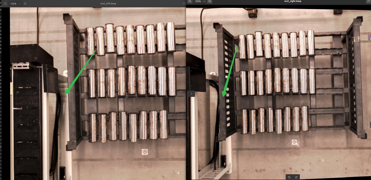
If the red-line image is normal but the point cloud is abnormal, changing either the scale factor or the minimum distance from the object to the camera can produce a normal point cloud. In practice, adjust the minimum distance from the object to the camera first.
| Example | Red-Line Image | Point Cloud |
|---|---|---|
| Abnormal | 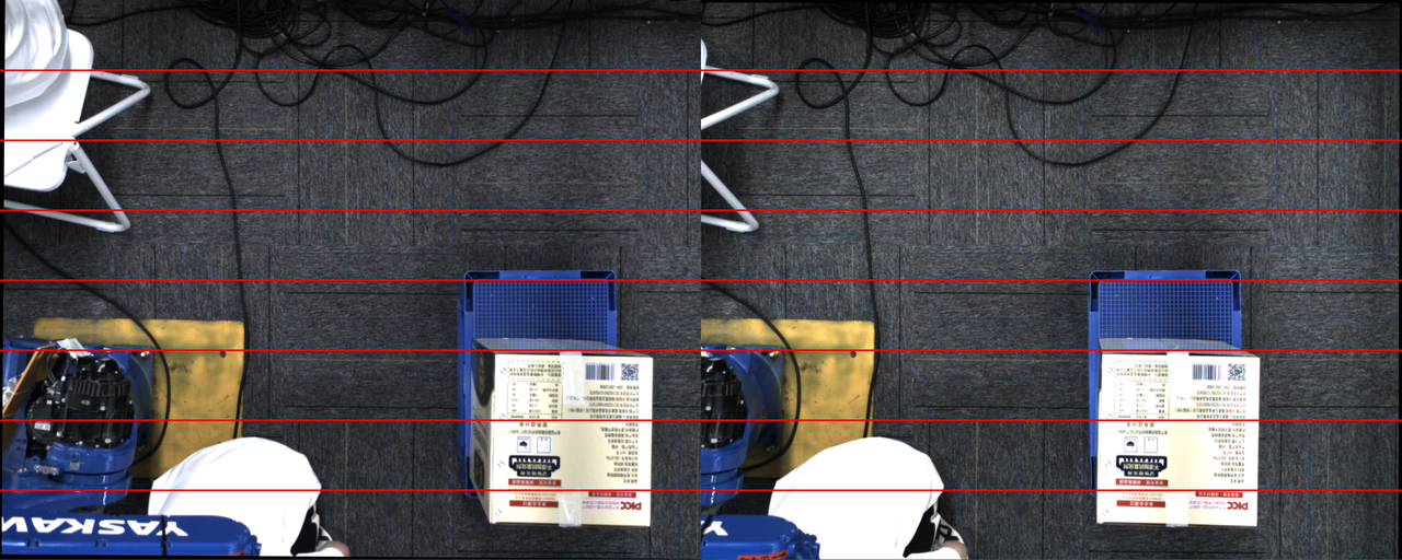 | 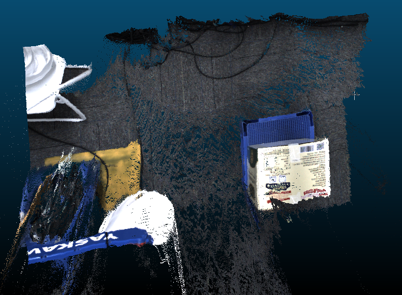 |
| Normal | 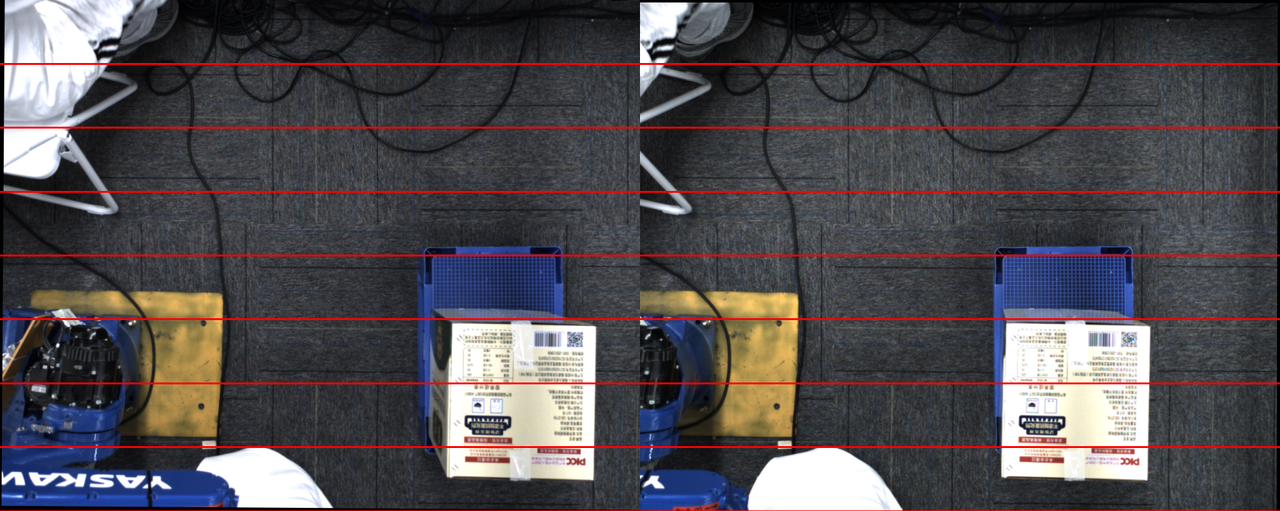 | 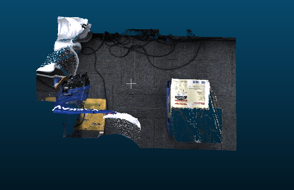 |
1.6 Localized Overexposure in a Stereo Camera’s 2D Image
Issue: Uneven lighting across a target causes localized overexposure in the stereo camera’s 2D image.
Possible causes: HDR exposure mode is not enabled, or the lighting is abnormal.
Solution:
- For simple scenes with large objects, such as sacks and cartons:
Enable HDR. Texture becomes visible in locally overexposed areas of the target’s surface, improving the point cloud.
For unevenly lit targets with complex shapes, such as cylinders or other specific shapes:
Stereo imaging currently cannot resolve this, as in the following scenarios.
1.7 Optimizing the Capture Cycle Time of a High-Resolution Stereo Camera
Issue: A single capture takes too long with a high-resolution stereo camera (nearly or more than 8~10s per capture).
Possible causes:
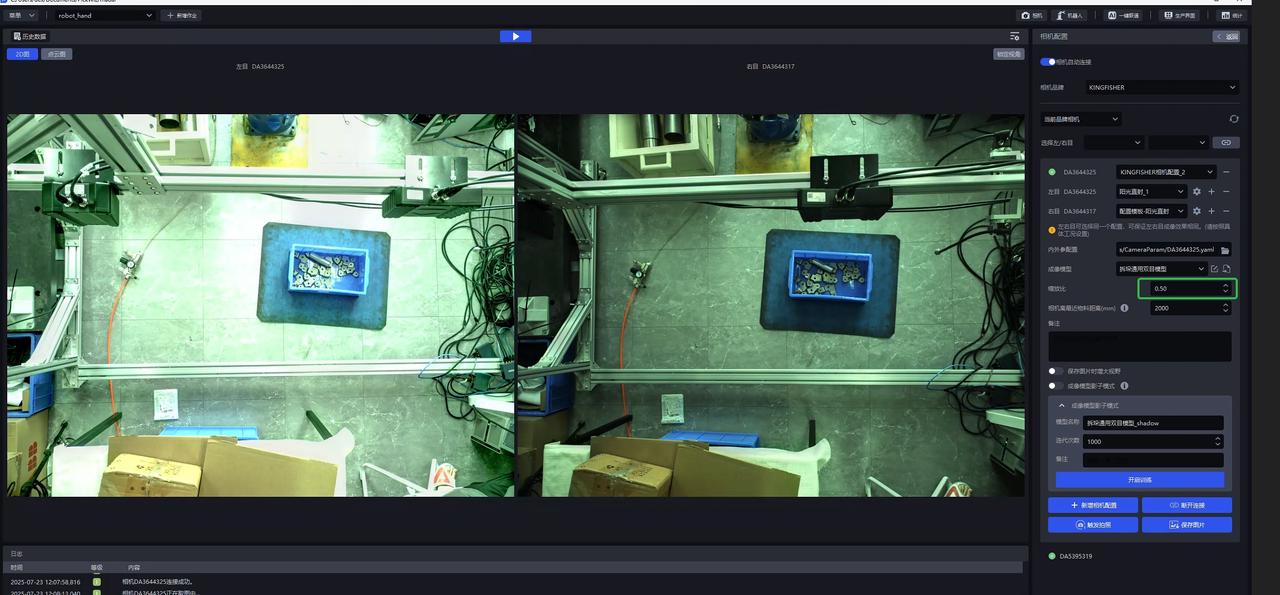
The scale factor is set to 1.0, producing images that are too large for a high-resolution camera.
HDR is enabled, triggering multiple image acquisitions.
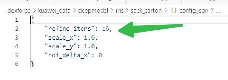
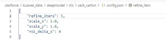
Model inference uses the default 16 refinement iterations, which take too long for high-resolution images.
Solution:
- Check whether the scale factor on the capture screen is set to 0.5.
- Check whether HDR is disabled.
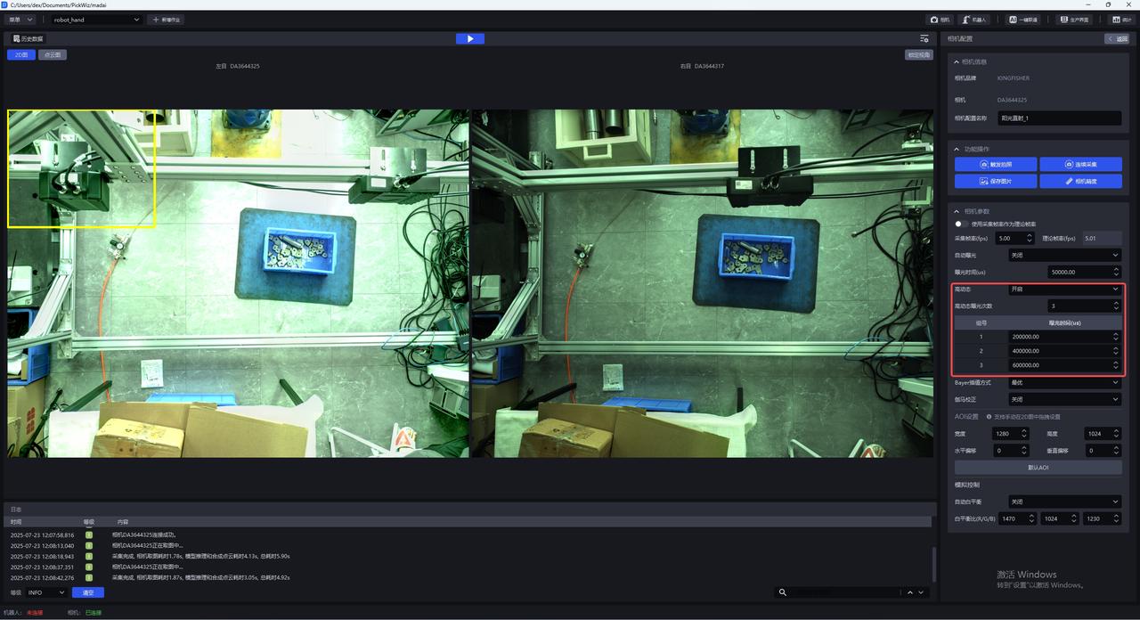
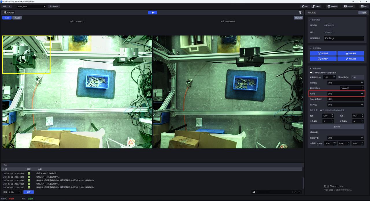
- In the
C:\Users\dex\.dexforce\kuawei_data\deepmodel\iris\sack_carton\config.jsonfile, change the "refine_iters" field from 16 to 5. Restart the software after making the change.
- Note that point cloud quality may decline. Use the product’s stereo shadow mode to adapt the model (requires >=1.7.6).
1.8 Black Lines in Images from a Stereo Camera
Issue: Black lines appear in images acquired from the stereo camera, as shown below.
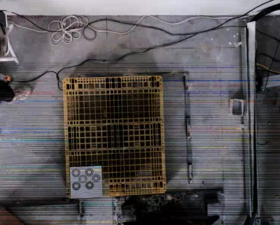

Possible cause: The customer replaced the network cable with a longer one, causing unstable network speed. Network issues can produce black lines in images acquired by the KINGFISHER stereo camera.
Solution: First, check the network conditions and the network cable on site.
2. Mask Mode & Shadow Mode
2.1 Differences Between Mask Mode and Shadow Mode
Question: What is the difference between Mask Mode and Shadow Mode, and when should each be used?
Answer:
Mask Mode: Quickly generates training data from textures and synthetic data, then uses it directly for training. Its detection capability covers scenes corresponding to the supplied textures. If multiple textures are provided, it can detect boxes or sacks with those textures. It is generally used when detection of actual materials fails (for example, the recent Yushi case, where detection performance was poor). Versions after 132 support this mode. Training on an industrial PC is expected to take less than 1h.
Shadow Mode: Uses real data collected while the model runs in the actual scene for further training. It is generally used when the detection success rate is already above 95%+ and the goal is to reach 99.9%. Versions after 130 support this mode. Training on an industrial PC is expected to take less than 1h (at least 100 data samples are required to start).
2.2 Where Mask Mode Texture Data Is Saved
Question: Where is the texture data saved after training with Mask Mode?
Answer: In the corresponding project configuration folder.
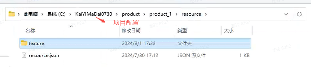
2.3 Training on a New Target with Mask Mode
Question: After obtaining model A through Mask Mode training, a different type of box is added at the site. Can Mask Mode training continue using A as the starting model?
Answer: Yes. Select the corresponding model for Mask Mode training and add the new textures.
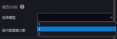
2.4 Mask Mode Training Has No Effect
Question: Why is there no change in performance after using Mask Mode?
Possible causes: The target model was not updated, or the selected texture region is incomplete.
Solution:
2.5 Mask Mode Training Fails
Question: Mask Mode training fails.
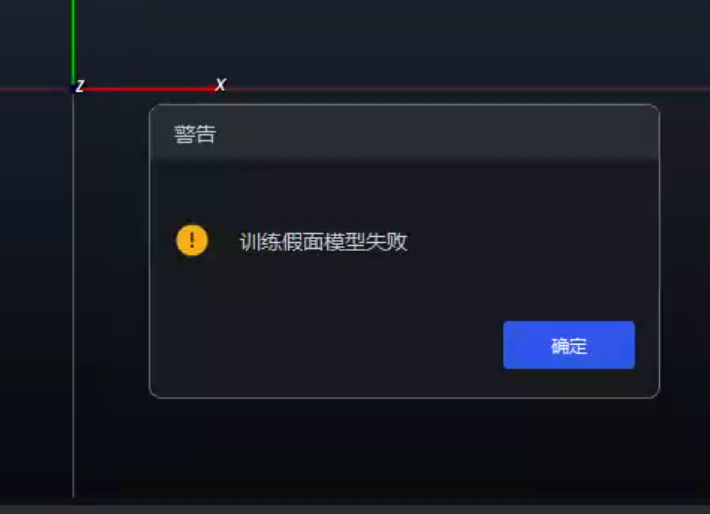
Possible causes:
Solution:
A code bug may have prevented the folder from being created.
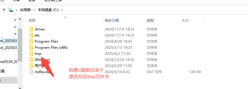
If the folder is missing, create it and run Mask Mode or Shadow Mode again.
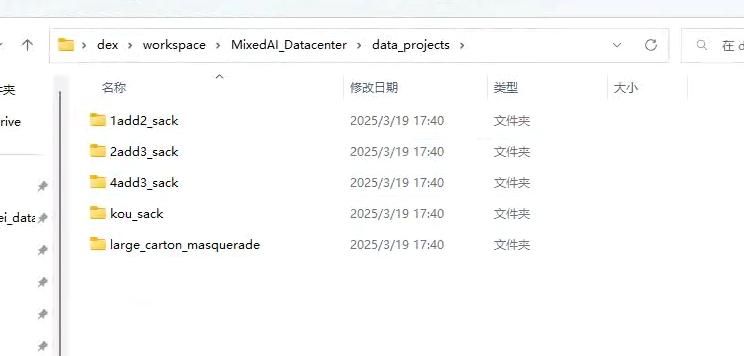
A sudden power loss or direct restart may have corrupted files.
- Check the 5 folders under this path. Each folder contains an info.yaml file. If an info.yaml file is corrupted and cannot be opened normally, proceed to step 2.
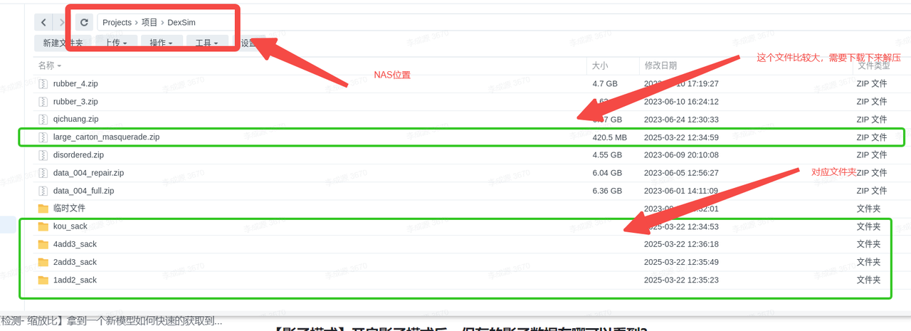
- Find the corresponding folders on the NAS at the location shown below (one folder needs to be decompressed). After decompression, replace the folders with the same names in data projects shown above. (Delete the folders in data projects before copying in the replacements.)
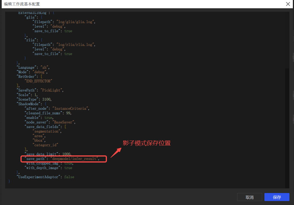
2.6 Where Shadow Data Is Saved
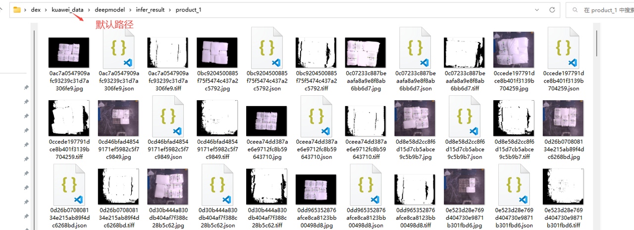
Question: After enabling Shadow Mode, where can I find the saved shadow data?
Answer: By default, it is saved under kuawei_data. The save path can also be changed (the default path is recommended).
2.7 Shadow Mode Training Has No Effect
Question: Why is there no change in performance after using Shadow Mode?
Possible causes: The model was not updated, or the target types do not match.
Solution:
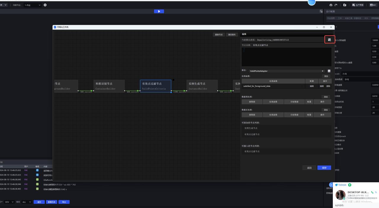
2.8 Where to Enable Shadow Mode
Question: Where is Shadow Mode enabled for randomly arranged and neatly arranged scenes?
Answer: Shadow Mode is enabled by default for both randomly arranged and neatly arranged scenes. If you are unsure, check it at the location shown below.
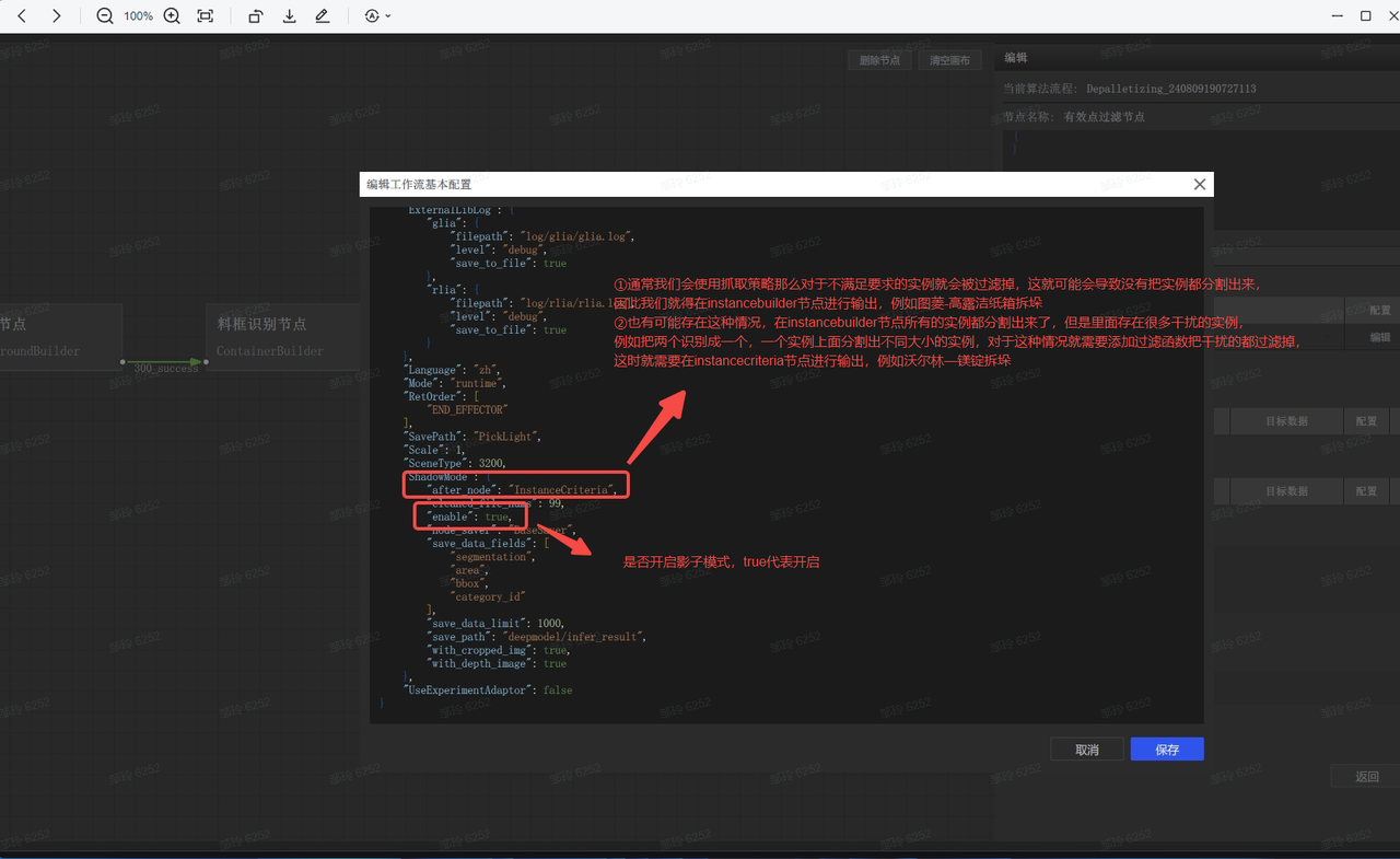
2.9 Changing the Shadow Mode Save Node 【1.6.0-1.7.0】 All Scenes
Question: How do I change the Shadow Mode save node?
Answer: Go to the project directory and locate the task configuration using the task ID.
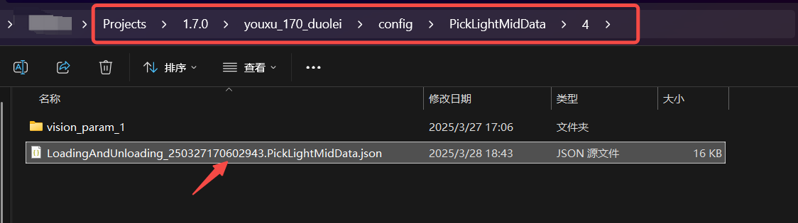
Open the configuration and modify the ShadowMode section.
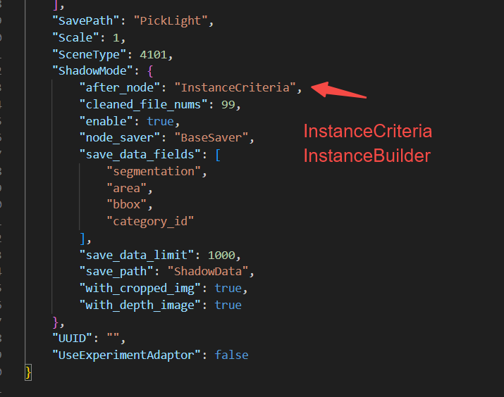
3. Depalletizing Scenarios
3.1 2D Recognition
3.1.1 Quickly Determine the Most Suitable Scale Factor
Question: How can I quickly determine the most suitable scale factor?
Answer:
Run inference locally using run.py (Windows).
3.1.2 Extract Top-Layer Texture - Individual Instances Are Not Recognized
Question: Some identically sized cartons arranged in an orderly pattern are not detected. Are there options besides optimizing the model?
Possible Cause:
Solution: Adjust the parameters for extracting top-layer texture so that only the topmost cartons are retained.
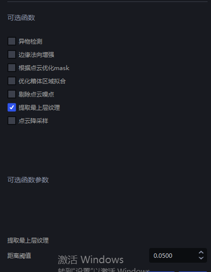
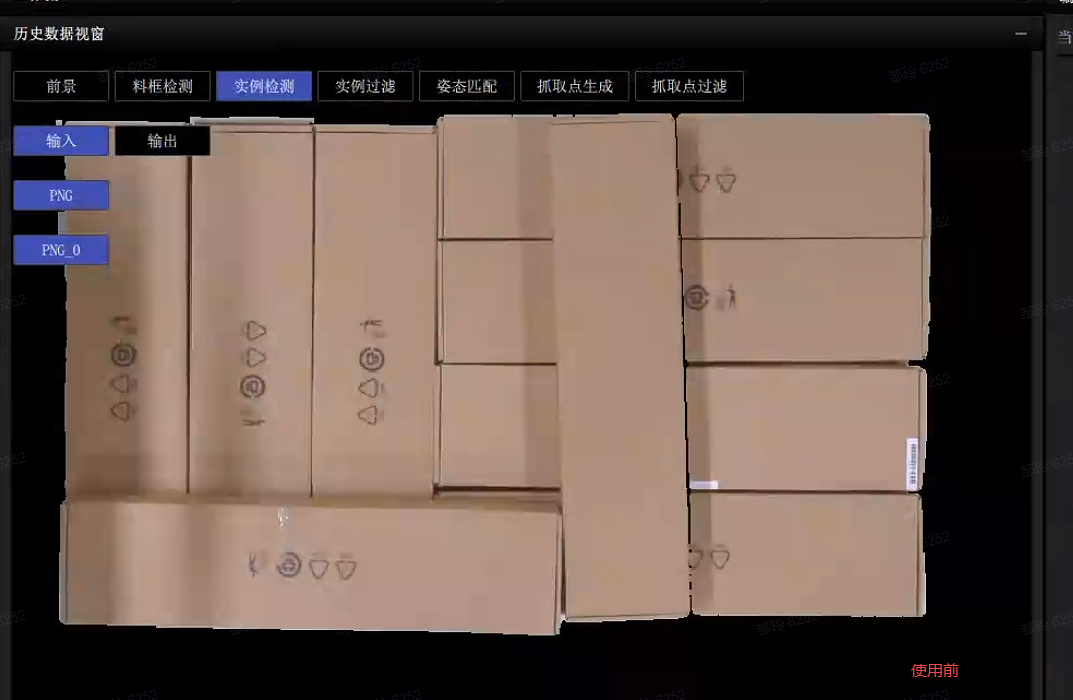
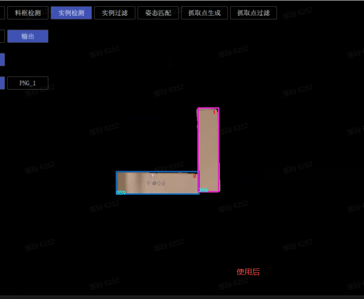
3.2 Pick Point Processing
3.2.1 Pose Adjustment
Question: By default, the software outputs carton coordinates with x pointing along the long side and y along the short side. How should the parameters be set to make y point along the long side?
Answer: Use one of the following settings:
RZ angle is not fixed (±180° rotation is acceptable)
- Add a fixed 90° rotation in the pick strategy.
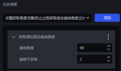
Rz angle is fixed
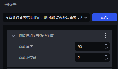
- First, add a fixed rotation angle for picking so that y points along the short side.
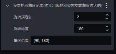
- Then, set the pick angle range according to the actual conditions.
3.3 Pick Accuracy
3.3.1 Pick Point Is Off-Center - Resolution
Question: Carton Instance Segmentation is correct and the mask is complete, but the pick point is off-center. How can I adjust it?
Possible Cause: The Pick Calculation - Resolution parameter may be too large, resulting in excessive spacing between calculated mask points.
Solution: Adjust the Pick - Resolution value as follows:

Parameter tuning
Use MeshLab to open the point cloud in the historical data folder. The historical data path is C:\Users\dex\kuawei_data\PickLight
MeshLab is a powerful 3D visualization and processing tool. Download it from https://www.meshlab.net/#download
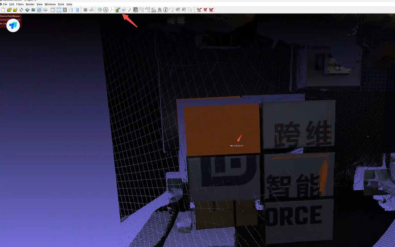
After opening the corresponding point cloud in MeshLab, click

Measure the distance between adjacent points and enter a nearby value.
In actual scenes, the point cloud spacing is smaller for objects on the upper layers and larger for objects on the lower layers. A slightly larger value is therefore recommended.
In the figure below, the measured point cloud value is 0.0016, so a nearby value such as 0.002 can be entered as the point cloud resolution.
3.3.2 Pick Angle Is Too Large
Question: Sack Instance Segmentation is correct and the mask is complete, but a bulge in the sack makes the pick angle too large. How can I reduce the angle?
Solution:
Adjust the patch size.
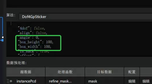
In the visual workflow, add
"box_width": 100and"box_height": 100to the dof4 algorithm. These values specify the patch size and can be adjusted to suit the sack.
3.3.3 Pick Point Is Off-Center - Side Is Included in Segmentation
Question: The detection appears correct, but the side of the sack is also included in the segmentation, causing the pick point to shift away from the center.
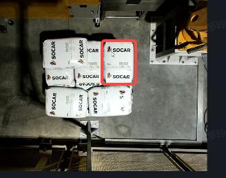
Possible Cause: The side is included in the calculation.
Solution: In the vision parameters, change Pick Calculation - Select Coordinate System from 1 (ROI coordinate system) to 2 (a coordinate system perpendicular to the sack).
3.3.4 Pick Point Is Off-Center - Large Pick Point Offset
Question: The segmentation mask is correct and complete, but the point cloud output by the pick point generation node is incorrect.
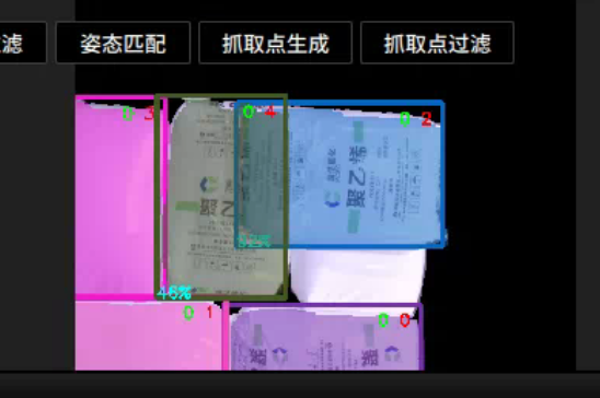
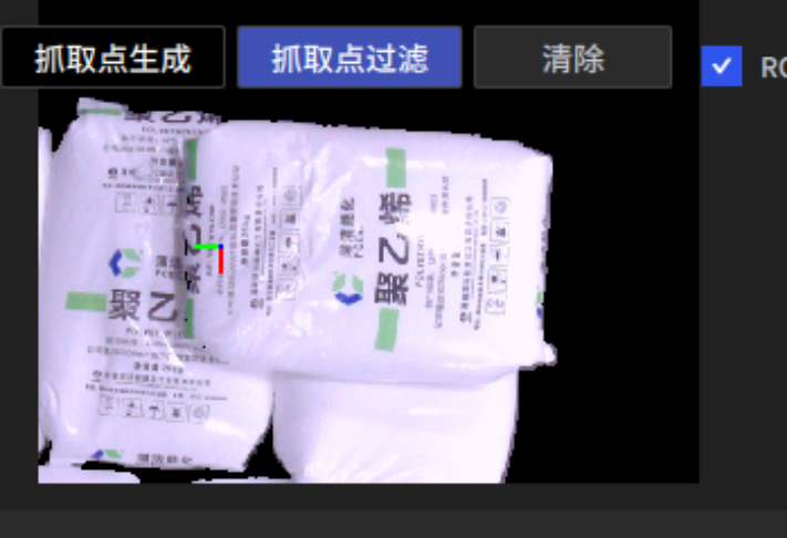
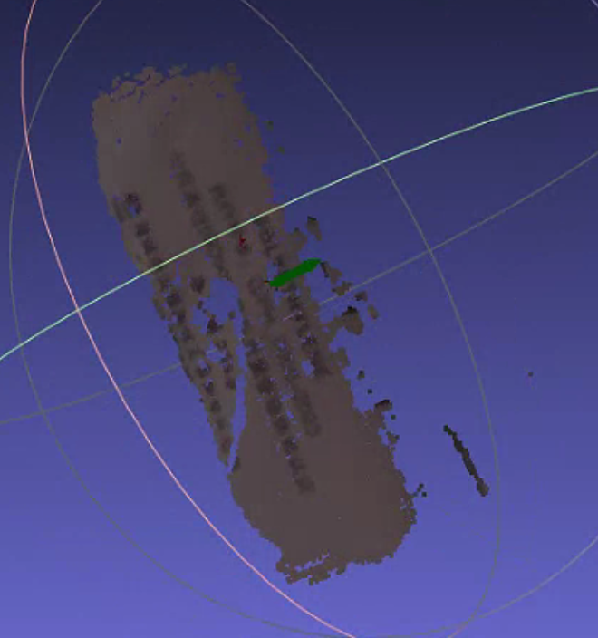
Possible Cause: This is usually caused by an incorrect parameter in an optional function. For example, if the average distance ratio in the point cloud removal function is set too low, many points in the sack’s point cloud are removed, shifting the pick point.
Solution: Adjust the parameter settings.
3.3.5 Pick Point Is Off-Center - Coarse Segmentation
Question: The sack’s segmentation box is too large, and its mask merges with the lower layer, shifting the pick point. How can this be resolved?
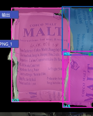
Solution: Because the mask is too large, the sack’s point cloud merges with the lower-layer point cloud. Remove the lower-layer points and retain only the upper-layer point cloud.
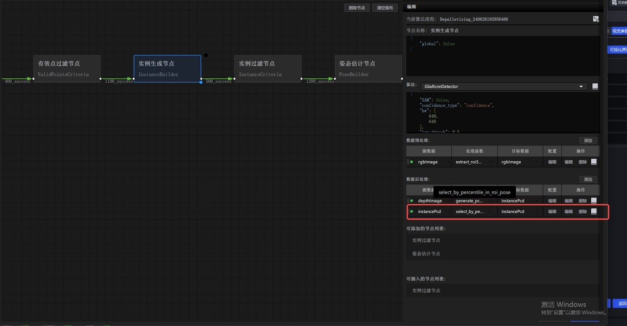
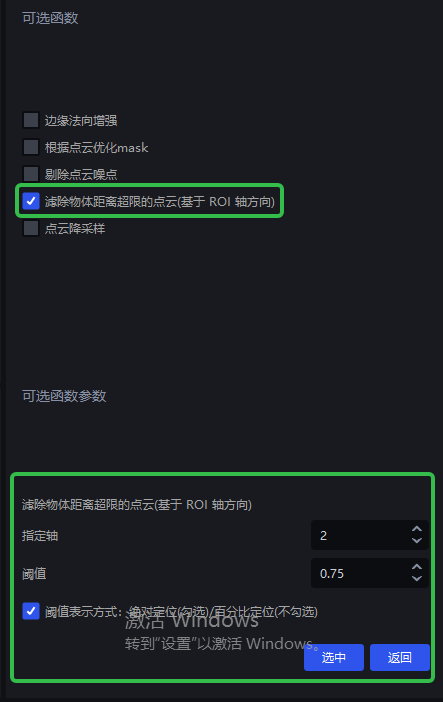
- In the vision parameters, enable the optional function Filter Out Point Cloud Points Beyond the Object Distance Limit (Based on the ROI Axis Direction) (v1.4.2).
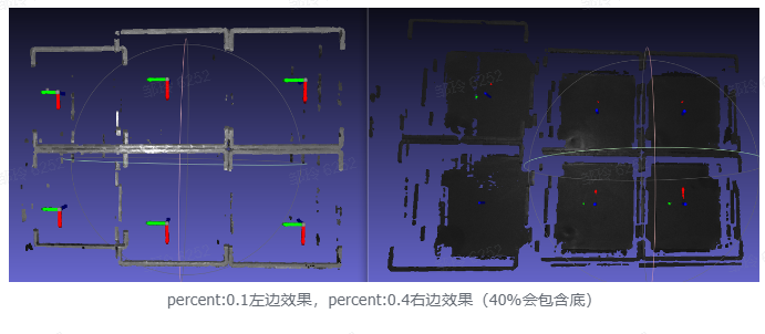
3.3.6 Pick Point Is Off-Center
Question: The segmentation result and mask both look correct, but the pick point is off-center. How can this be resolved?
Possible Cause: Too many noise points are attached to the instance.
Solution: Check the output of the pick node in the corresponding historical data and enable point cloud noise removal.
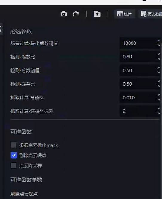
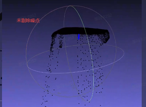
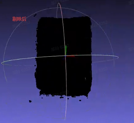
3.3.7 Pick Point Mode: 4-Axis/6-Axis (≤1.4.1)
Question: Where is the corresponding coordinate output configured for a four-axis robot arm?
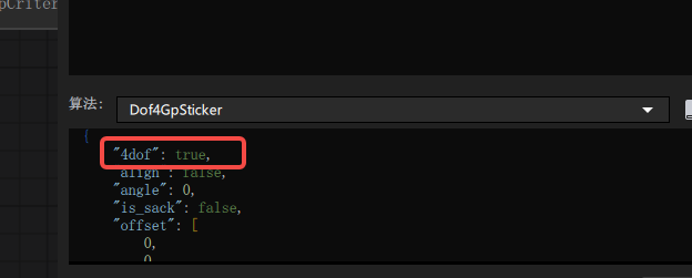
Answer: For a four-axis robot arm, set 4dof to true in the dof4 algorithm configuration of the pick point generation node. For a six-axis robot arm, set it to false. This requires opening the visual workflow.
3.4 Optional Functions
3.4.1 fill_hole Produces Noise in the Point Cloud After Hole Filling
| Version Dependency | Where to Add It | Source Data | Target Data |
|---|---|---|---|
| PickLight >= 1.5.0 | Post-processing of the foreground node or preprocessing of the instance generation node | depthImage | depthImage |
Use glia-0.3.3 or later.
Question: When using fill_hole to fill holes in the visual workflow, pyramid-like stepped noise appears, as shown below.
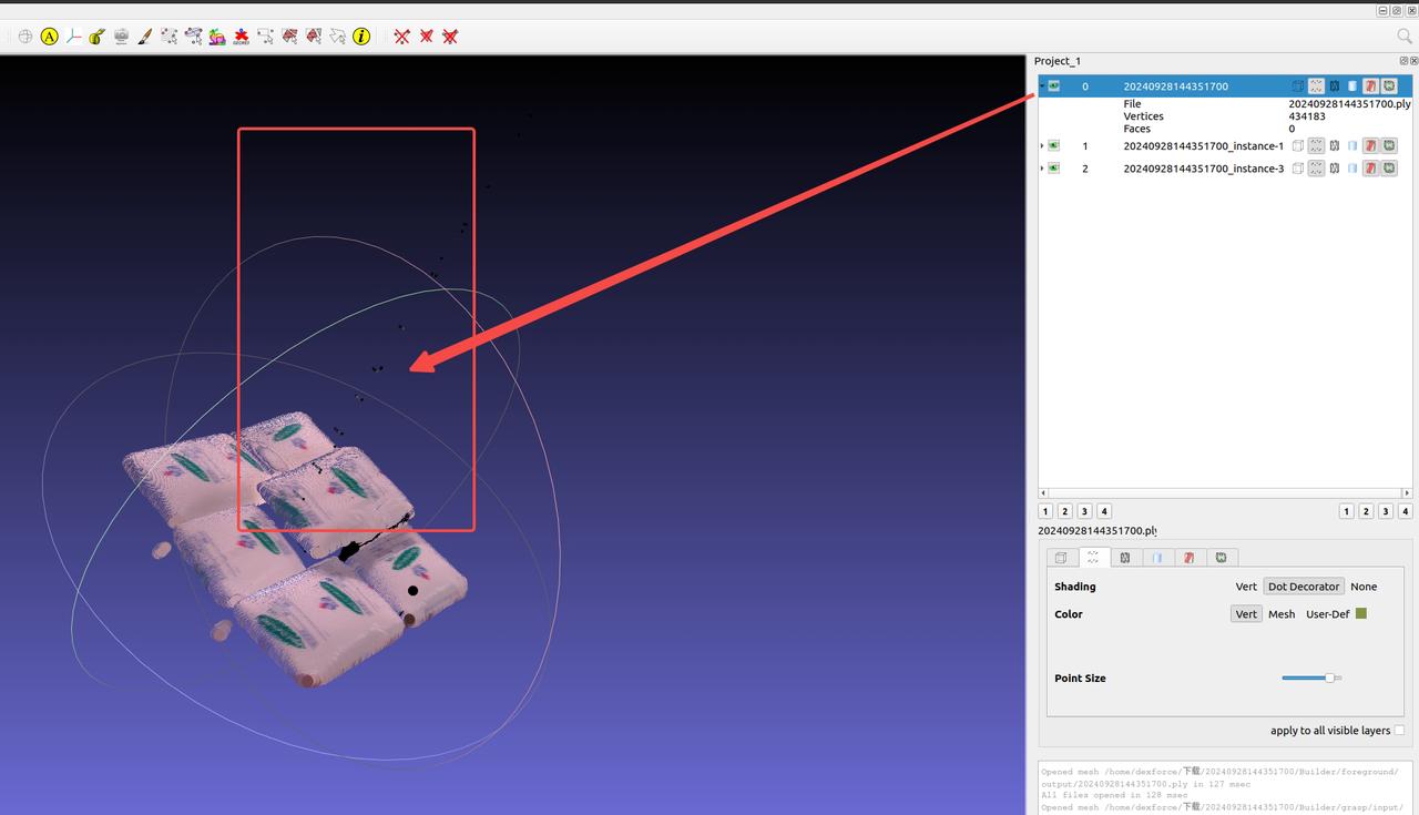
Possible Cause: Areas with a depth of 0 in the depth image interfere with hole filling. This was fixed in pickwiz versions >=1.5.0.
Solution:
Contact the product and R&D teams for support in updating the software version at the site.
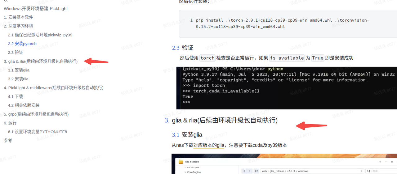
Confirm or upgrade to glia >= 0.3.3. Refer to Windows Development Environment Setup - PickLight and find the corresponding glia-0.3.3 version to download, as shown.
Confirm or upgrade to pickwiz >= 1.5.0, or upgrade the backend whl package to release-1.4.5.1 (commit version >=xxx, PR pending merge).
After updating, restart the software and run the historical data again.
3.4.2 Using the filter_by_color Function
Question: Instance generation produces false detections on the bottom pallet or other areas.
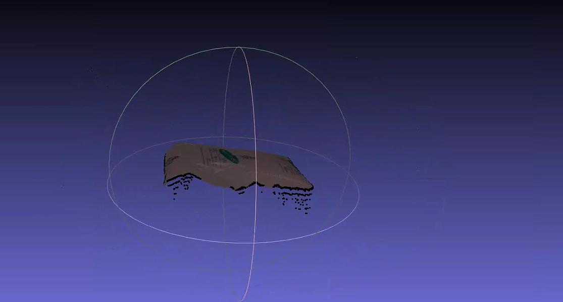
Solution: When instance generation incorrectly detects the bottom pallet or another area as a Target to pick, first examine how those detected instances differ from the actual Targets.
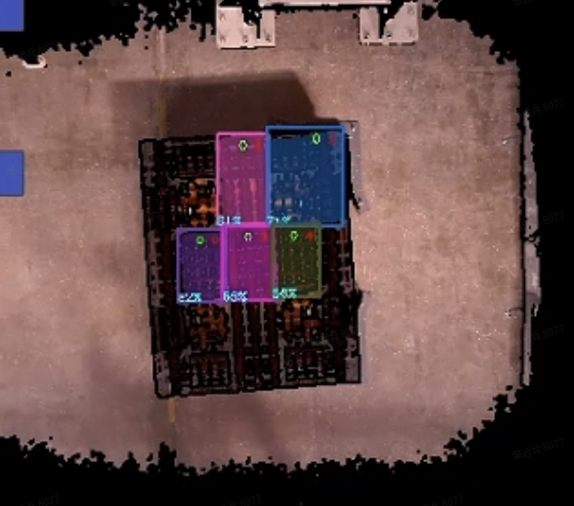
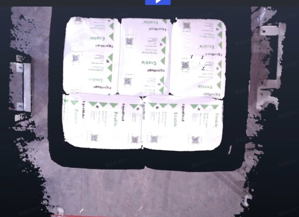
For a scene like the one above, where the sacks and pallet differ greatly in color, add filter_by_color in the visual workflow to filter by specified lower and upper color bounds.
- Add filter_by_color to the instance filtering node.
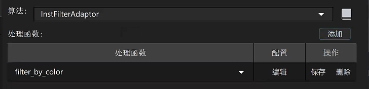
- Parameter descriptions
| Parameter | Value | Description |
|---|---|---|
| min_c | 0.1 | Minimum value for color filtering; 0 is black and 1 is white. |
| max_c | 2 | Maximum value for color filtering; it must not be less than min_c. |
| threshold | 0.7 | Filtering threshold. An instance is filtered out when the ratio of points in its mask whose colors fall within (min_c, max_c) to the mask area is below this threshold. |
| inverse | false | Whether to invert the selection. If true, points in the mask with colors below min_c or above max_c are used to calculate the threshold. |
The settings above filter out pallet instances containing black, leaving only sack instances.
3.4.3 is_top_safety Checks for Obstructions Above a Pick Point
Question: How can I determine whether an object to be picked is unobstructed and safe in certain scenes?
Answer: Add the is_top_safety function to the instance filtering node.
- Parameter descriptions
| Parameter | Default Value | Description |
|---|---|---|
| x_length | 1.0 | Required to generate the cuboid. Defines the length along the pick pose’s x direction within which obstructions are checked. |
| y_width | 1.0 | Required to generate the cuboid. Defines the width along the pick pose’s y direction within which obstructions are checked. |
| z_depth | 2.0 | Required to generate the cuboid. Defines the width along the pick pose’s z direction within which obstructions are checked. |
| bindwidth | 0.1 | Distance threshold in the z direction, in m. Point cloud points whose height difference from the pick point in the z direction exceeds this distance are considered obstruction points. |
| num_threshold | 1000 | If the number of obstruction points exceeds this threshold, the pick point is considered obstructed. |
| debug | false | Whether to save point cloud data for checking whether the generated cuboid is appropriate. |
| save_path | "" | Data save path. On Windows, separate path components with \\. |
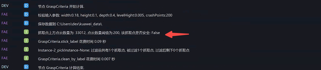
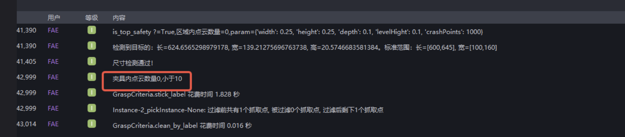
3.4.4 is_safety Checks Whether the Gripper at a Pick Point Will Collide
Question: What does the is_safety function do?
Answer: It filters out pick points where a collision may occur. It applies when a robot arm uses a gripper to pick an object and the gripper model is known.
- Parameter descriptions
| Parameter | Default Value | Description |
|---|---|---|
| prewin | 100 | In pixels. Generates a mask within the specified pixel range around the pick point for subsequent collision checks. A value that is too large may increase processing time and cause calculation errors. Set it slightly larger than the pixel length of the Target mask’s long side; assess it using the data in debug_vis. |
| threshold | 1.0 | Threshold for determining whether a pick pose is safe. If the number of point cloud points inside the gripper exceeds this threshold, the pose is considered unsafe. |
| roi_crop | true | Whether to crop the point cloud, retaining only points within the roi3d range. |
| debug_vis | "" | Path for saving debug data. Information from the debugging process is saved to the specified path. mask.png: mask region generated by the prewin parameter; object_mask.png: instance object mask; shell_mask.png: difference between those two masks, used to identify the surrounding region for collision checks; crop.ply: surrounding point cloud used for collision checks. |
| use_projected_mask | false | Whether to use model projection. If false, the mask passed from the instance generation node is used. Enable this only when an accurate model of the Target itself is available. |
- Log showing the result
4. Loading and Unloading Scenarios (Ordered/Randomly Arranged)
4.1 Deep Learning Models
4.1.1 Incomplete Model Detection
Issue: The model does not detect all objects. The number of detections is capped for inference on each image (usually at 20).
Possible cause: The maximum number of detectable objects was set to 20 when the model was exported.
Solution: Contact the model provider to export the model again.
4.1.2 Abnormal Keypoints Detected by the Model
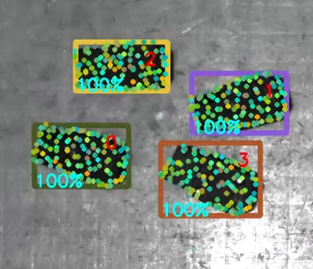
Issue: The model detects abnormal keypoints.
Possible cause: During one-click model training, we generate the keypoints by downsampling. The trained model generates a new set of keypoints.
Solution: Replace the original keypoints with the new ones.
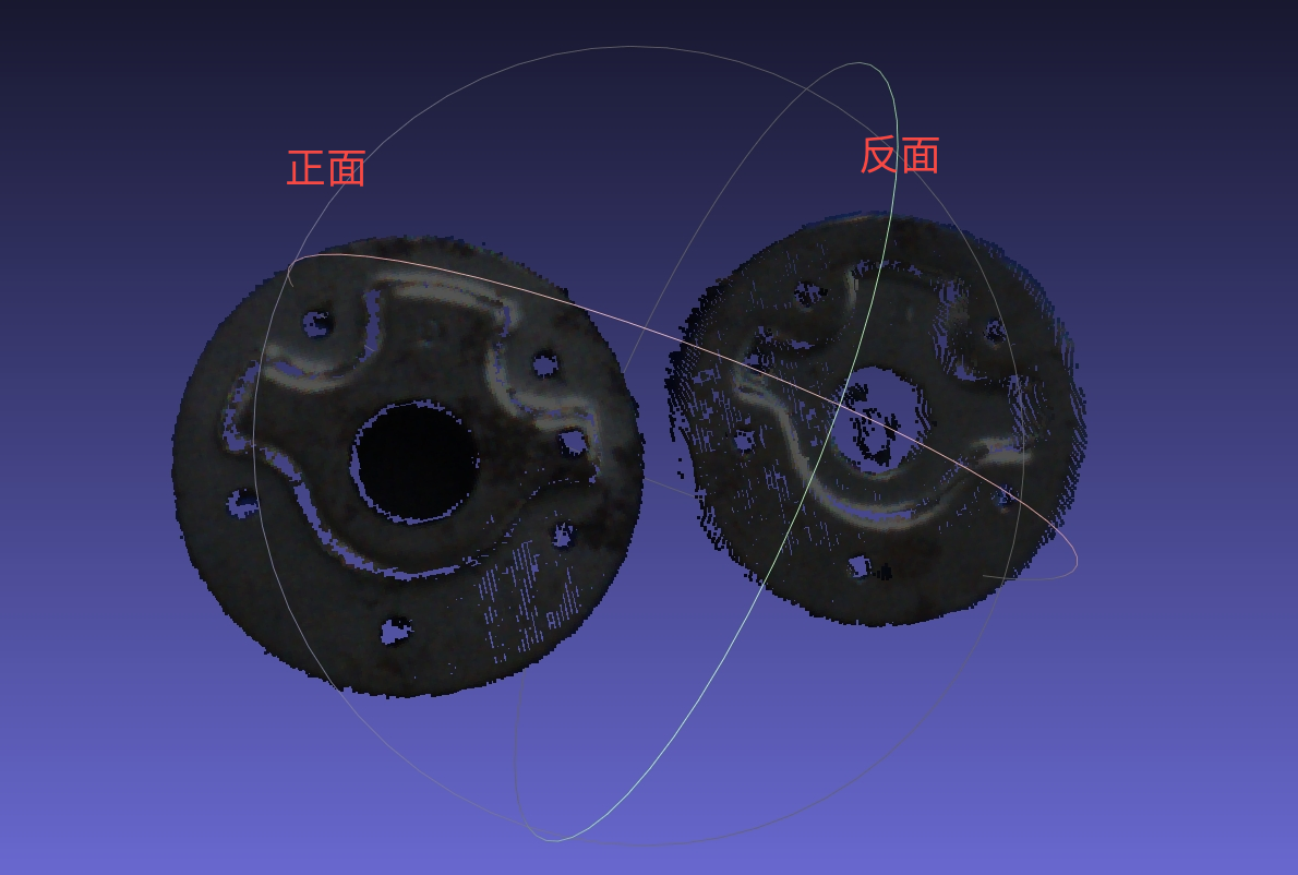
4.1.3 Creating Dual or Multiple Templates
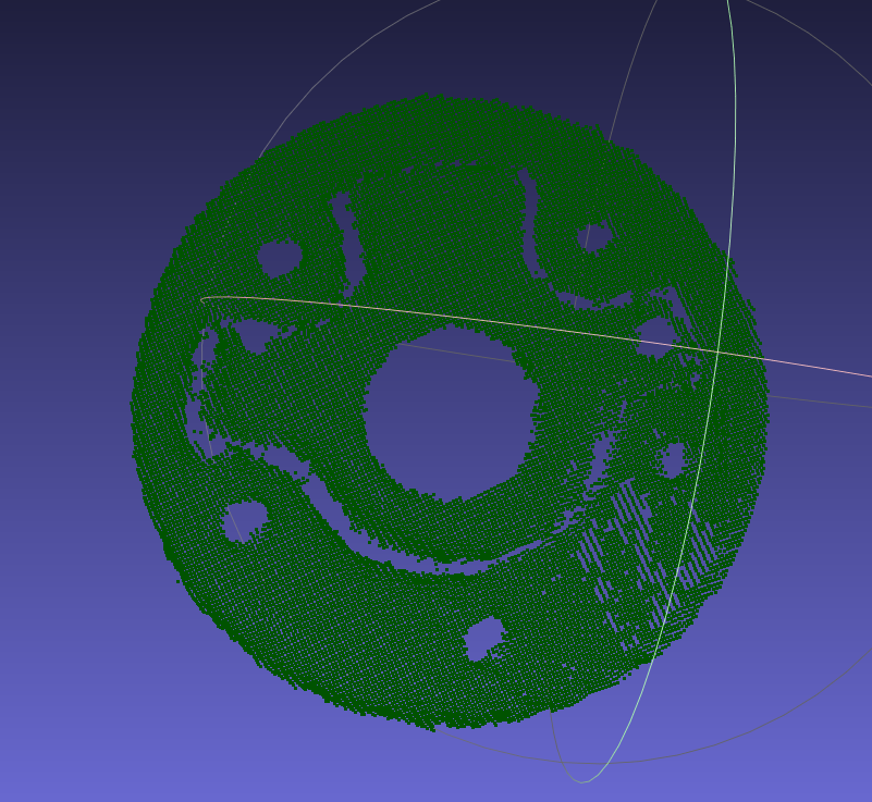
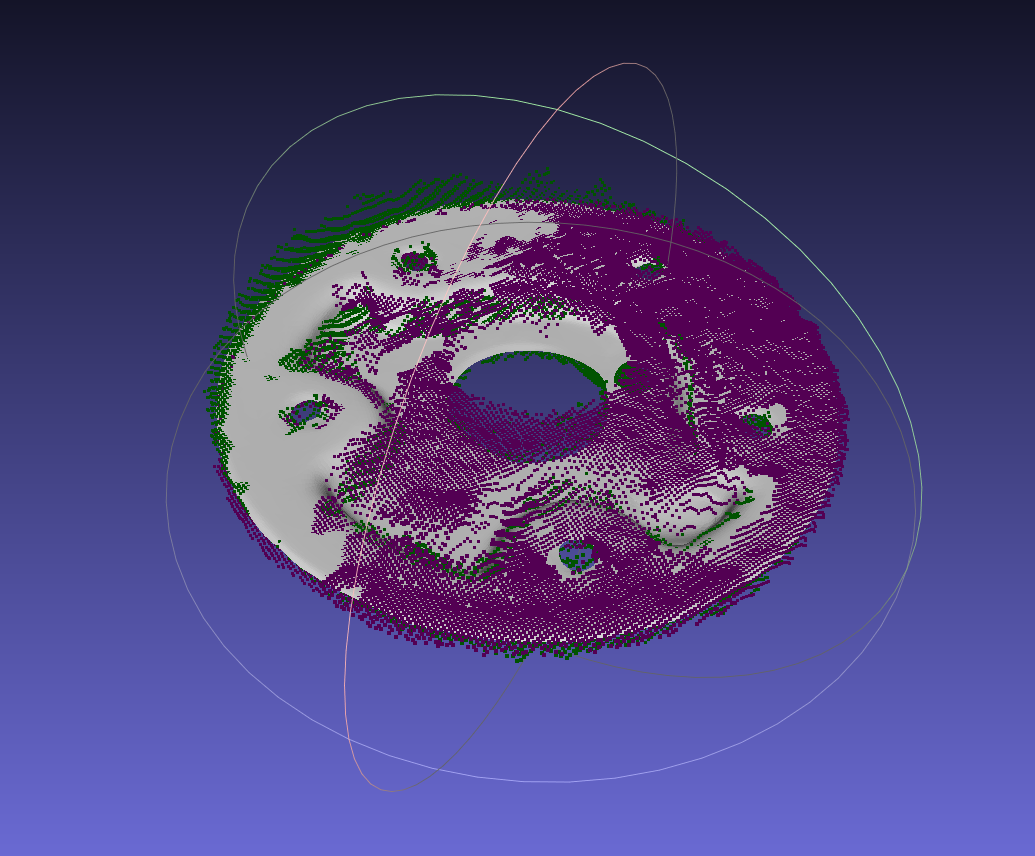
Capture point cloud files of the front and back of the target with the camera. Color each side separately, align them with the CAD model, and merge the colored point cloud files into a template point cloud file. Color the keypoint cloud file point by point so that the two colors are evenly distributed.
Steps:
|
|
|---|---|
|
 |
|  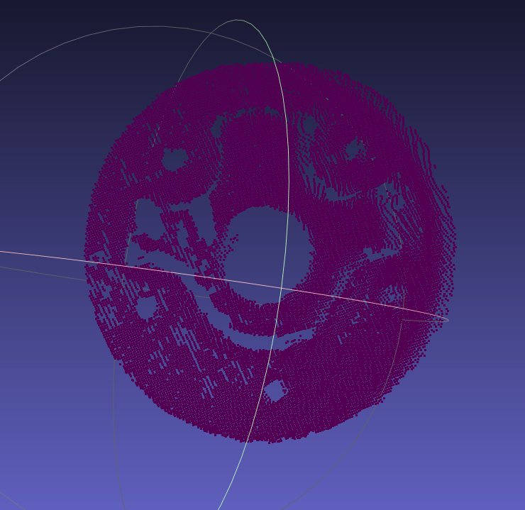 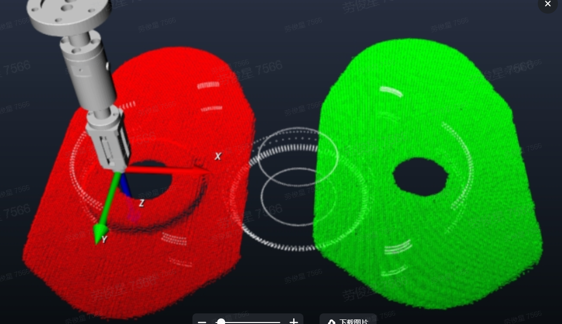 |
|  |
| |
| Similar to this: 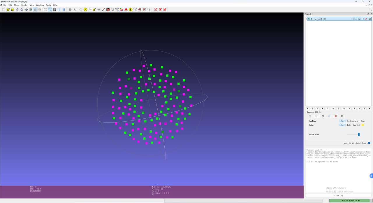 |
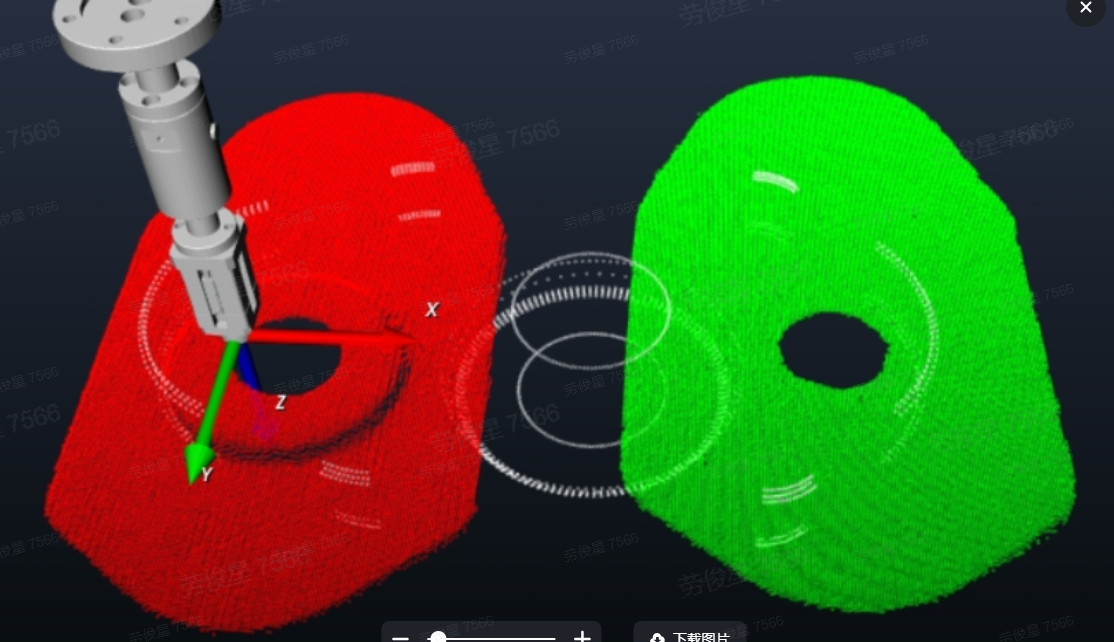
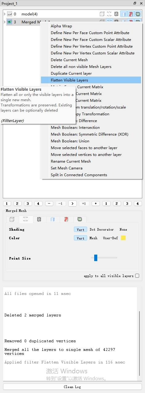
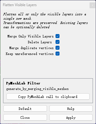
4.1.4 Creating and Using Dual Templates for Flat Targets with Identical Front and Back Shapes Using SpitialRansc Registration
Obtain three types of files:
A keypoint PLY file (keypoint_128.ply)
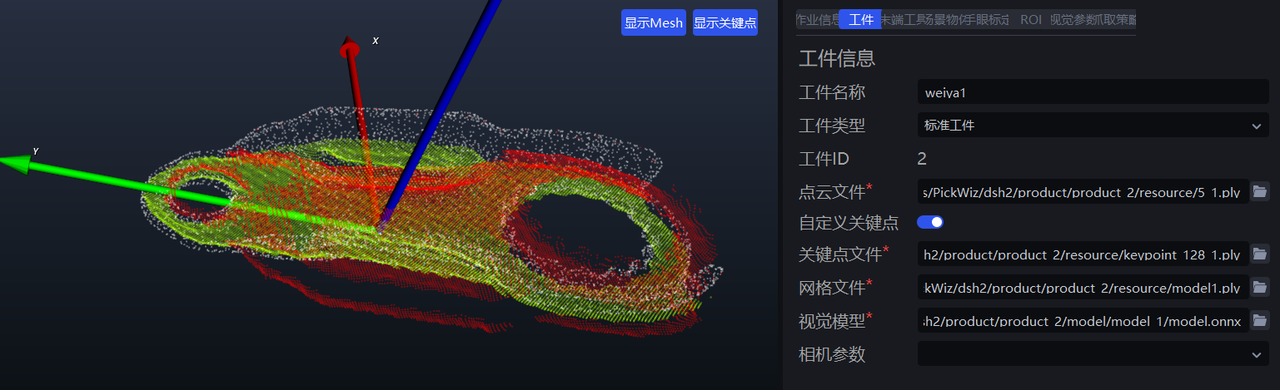
Front and back point cloud model files. These are generally extracted from the scene point cloud. Color the front template green and the back template red. (point_front.ply, point_back.ply)
A mesh model (model.ply)
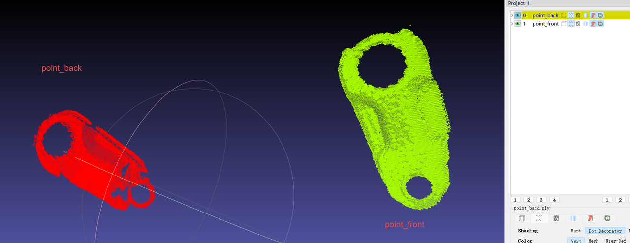
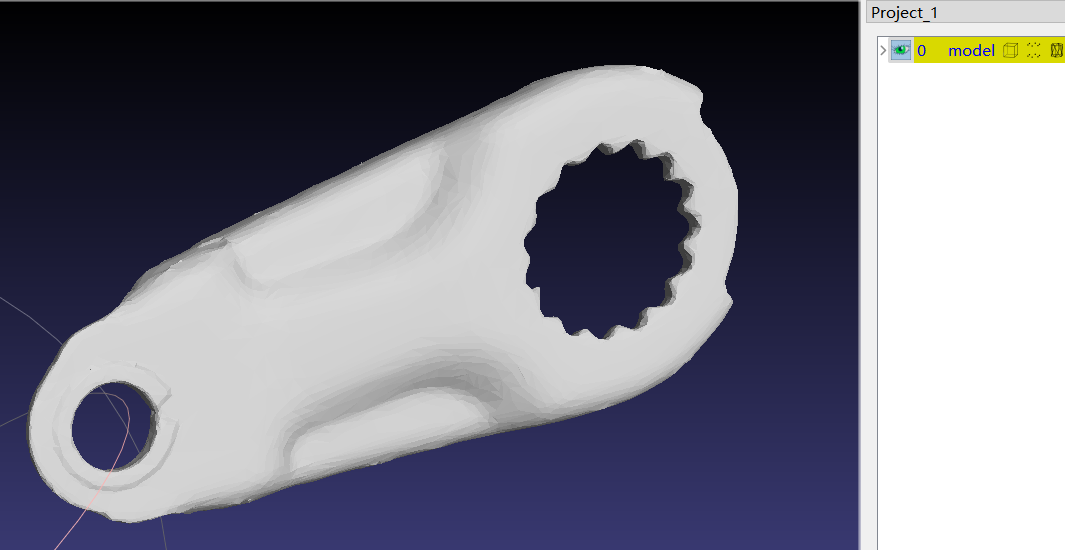
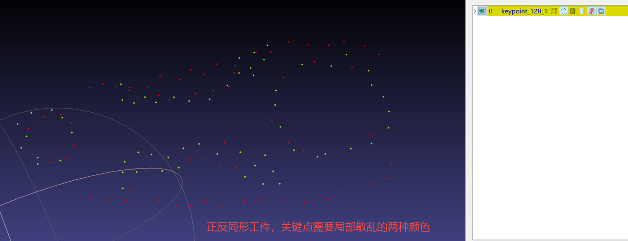
【For a three-dimensional target, color the keypoints in two colors by layer. The point cloud template only needs to include points visible to the camera.】
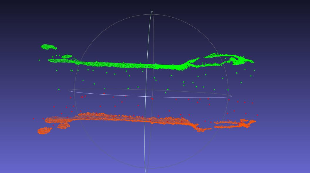
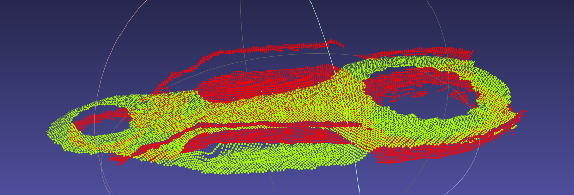
- After aligning both point cloud templates with the CAD model, merge the point clouds to generate a dual-template PLY point cloud file. 【After aligning the point cloud files with the CAD model, save each template separately so that you do not have to align them again if a template needs adjustment later.】
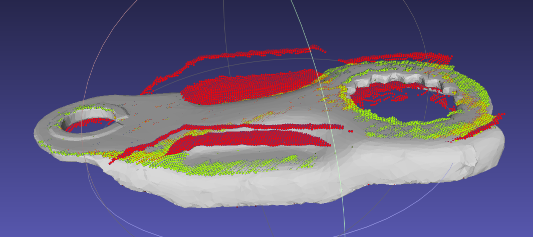
Import the three files into PickWiz.
【Note】: Check that the dual-template point cloud is aligned and colored with two colors. Check that the two colors are interspersed locally among the keypoints, and that each color corresponds to the same color in the templates.
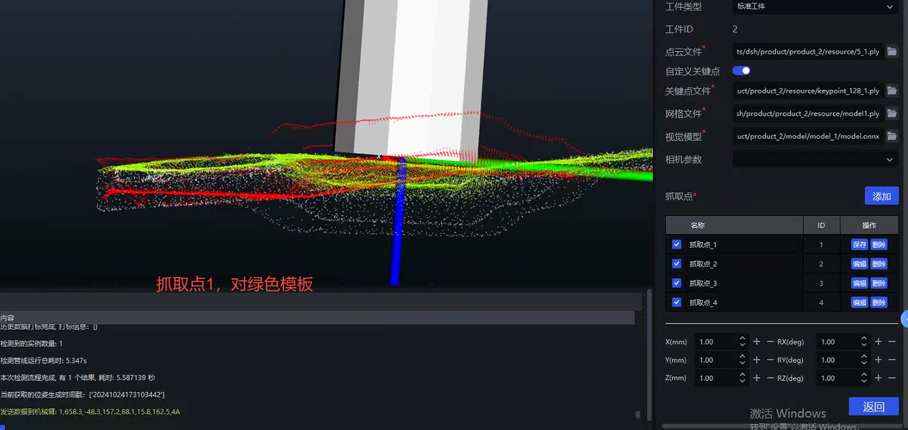
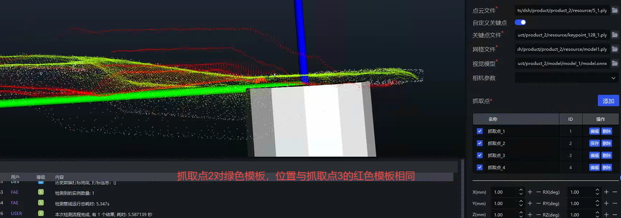
Create pick points.
【Note】: Create the pick points in order, and read the requirements for each pick point carefully.
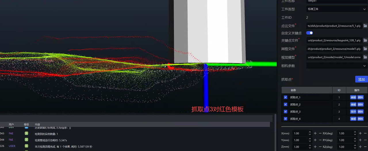
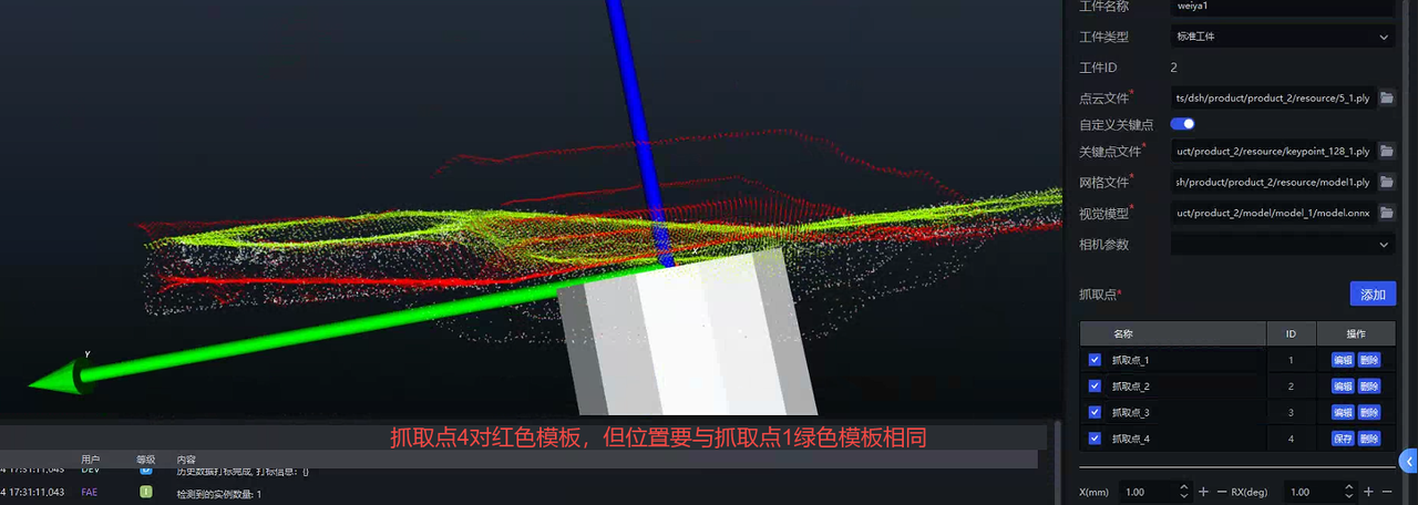
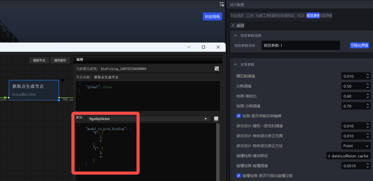
- Open the visualization interface and add the dual-template binding information.
{
    "model_to_pick_binding": {
        "0": [
            1,
            2
        ],
        "1": [
            3,
            4
        ]
    }
}
- Add the “Pick Point Number” selection to the robot settings.
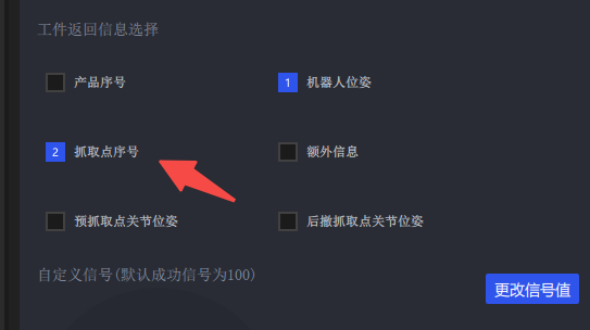
- Click Run. There are 4 possible returned pick point numbers (1, 2, 3, 4). If high accuracy is required, use a script to teach all 4 pick points.
4.1.5 Using Auto Augmentation to Improve Prediction Results Through Data Augmentation
For details, see the 2D Instance Segmentation Configuration Guide.
4.1.6 Verifying the CAD Model Used for Data Rendering
Current ways to obtain a CAD model:
The customer provides the original CAD model directly.
The actual target is scanned.
In either case, make sure the CAD model is correct, including its dimensions, orientation, and type.
Counterexample 1: The scanned target does not match the point cloud of the actual target (different opening angles).
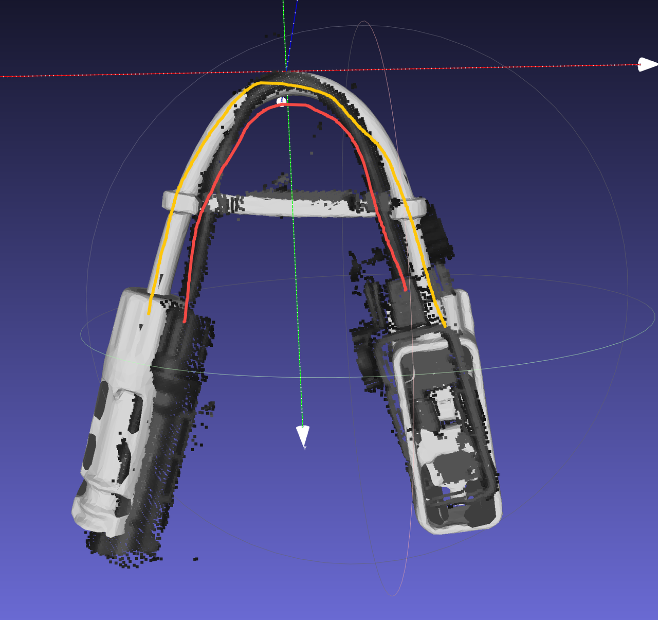
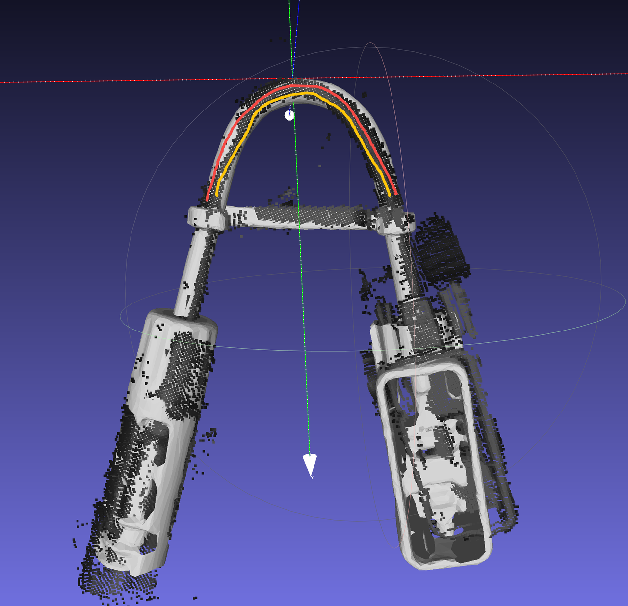
4.1.7 Exporting a TRT Model
Add the use-trt option when exporting the ONNX model.
python -m mixedai.scripts.export \
        --config-file config_path \
        --model-file model_path \
        --sample-image image_path \
        --use-trt
Use glia to export the TRT model.
Perform all the following operations in the pickwiz_py39 environment: conda activate pickwiz_py39
- rcnn
python -m glia.dl.utils.trt_converter \ --onnx onnx文件路径,如xxx.onnx \ --image 图片文件路径, 如xxx.png \ --model-type rcnn \ --saveEngine xxx.trt \- yolo
python -m glia.dl.utils.trt_converter \ --onnx onnx文件路径,如xxx.onnx \ --model-type yolo \ --saveEngine xxx.trt \- Stereo
python -m glia.dl.utils.trt_converter \
        --onnx onnx文件路径 \
        --model-type stereo \
        --saveEngine xxx.trt \
        --optShapes=image1:1x3x480x640,image2:1x3x480x640 \
        --fp32 \
        --workspace=6000 \
        --tacticSources=-CUDNN,+CUBLAS \
        –-builderOptimizationLevel=3
For more detailed export instructions, see: http://doc.open3dv.site/glia/doc/master/text/application/trt_converter.html
- Use glia to run inference with both the ONNX and TRT models and check whether their results match.
python -m glia.dl.utils.inference --image-file "./*.png" \
        --model-file .trt .engine or .onnx model \
        --output-dir ./ \
        --bbox-mode aabb (或者obb)\
            --scale 1.0
4.1.8 Configuring extract_roi3d_rgb
Remove the corresponding image areas outside the ROI3D region to eliminate the background.
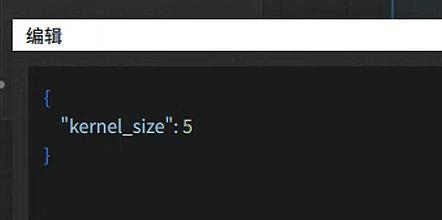
Parameter: fill kernel size
Before 1.5.1: kernel_size
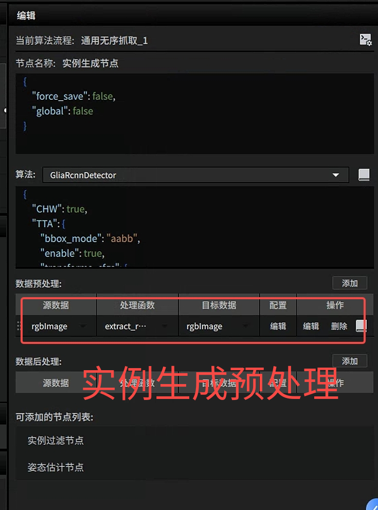
After 1.5.1:
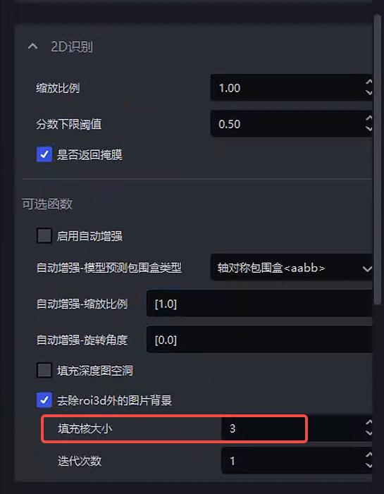
*******Note*******Missing point cloud data in the area to be detected can create holes in the image after background removal, affecting detection. In this case, increase the fill kernel size to fill the holes. The results are shown below.
| kernel_size | Original image | Detection result |
|---|---|---|
| 5 | 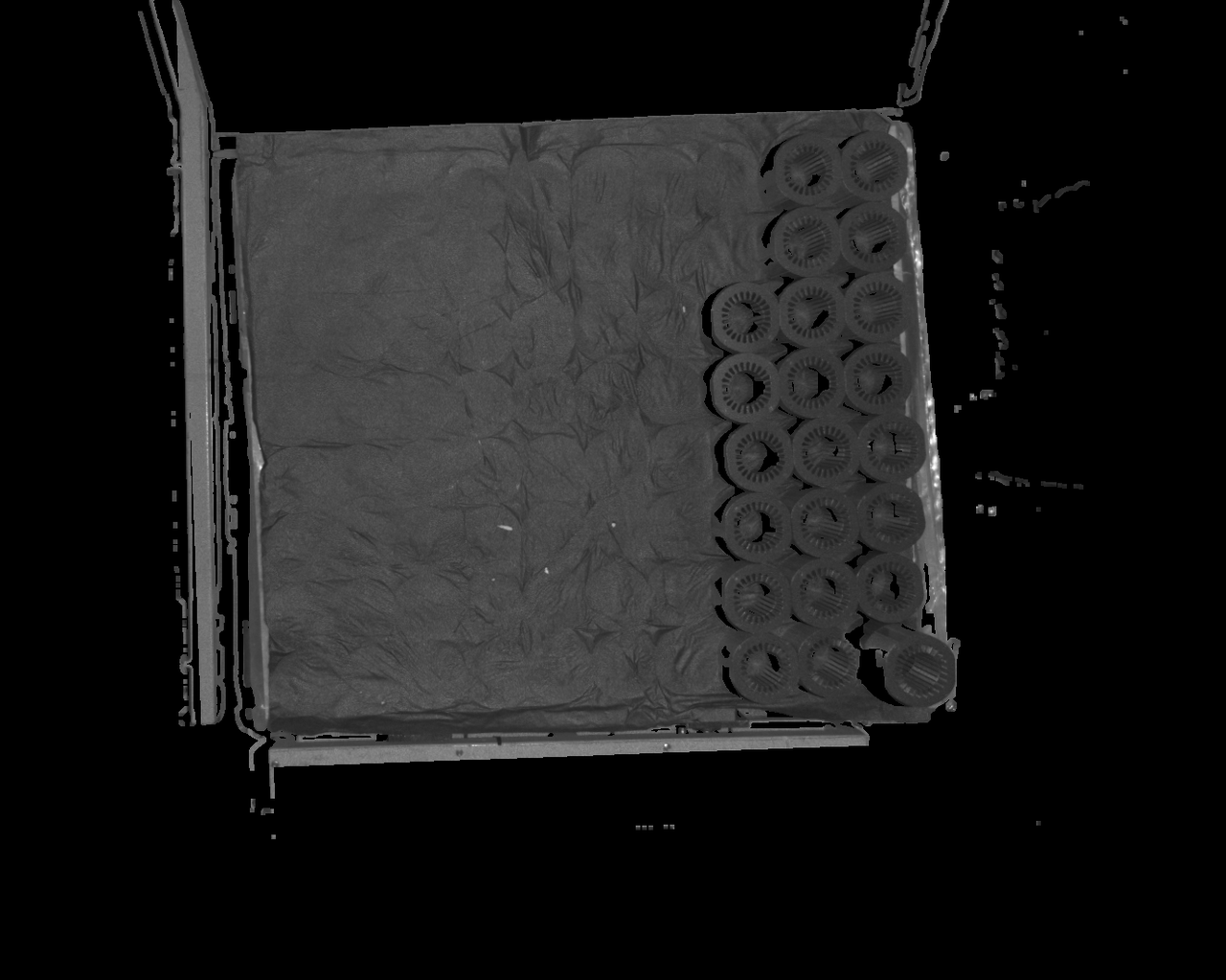 The default setting is 5. If point cloud data is missing in the area to be detected, that area may have many holes, affecting detection results. | 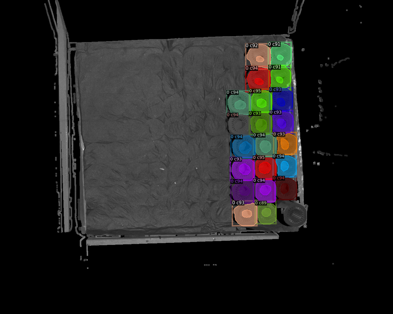 |
| 7 | 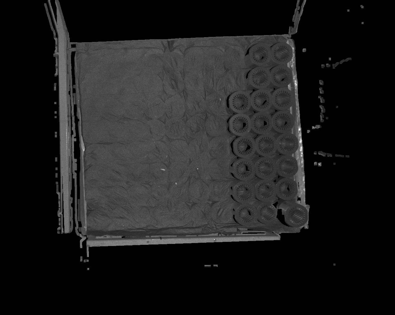 | 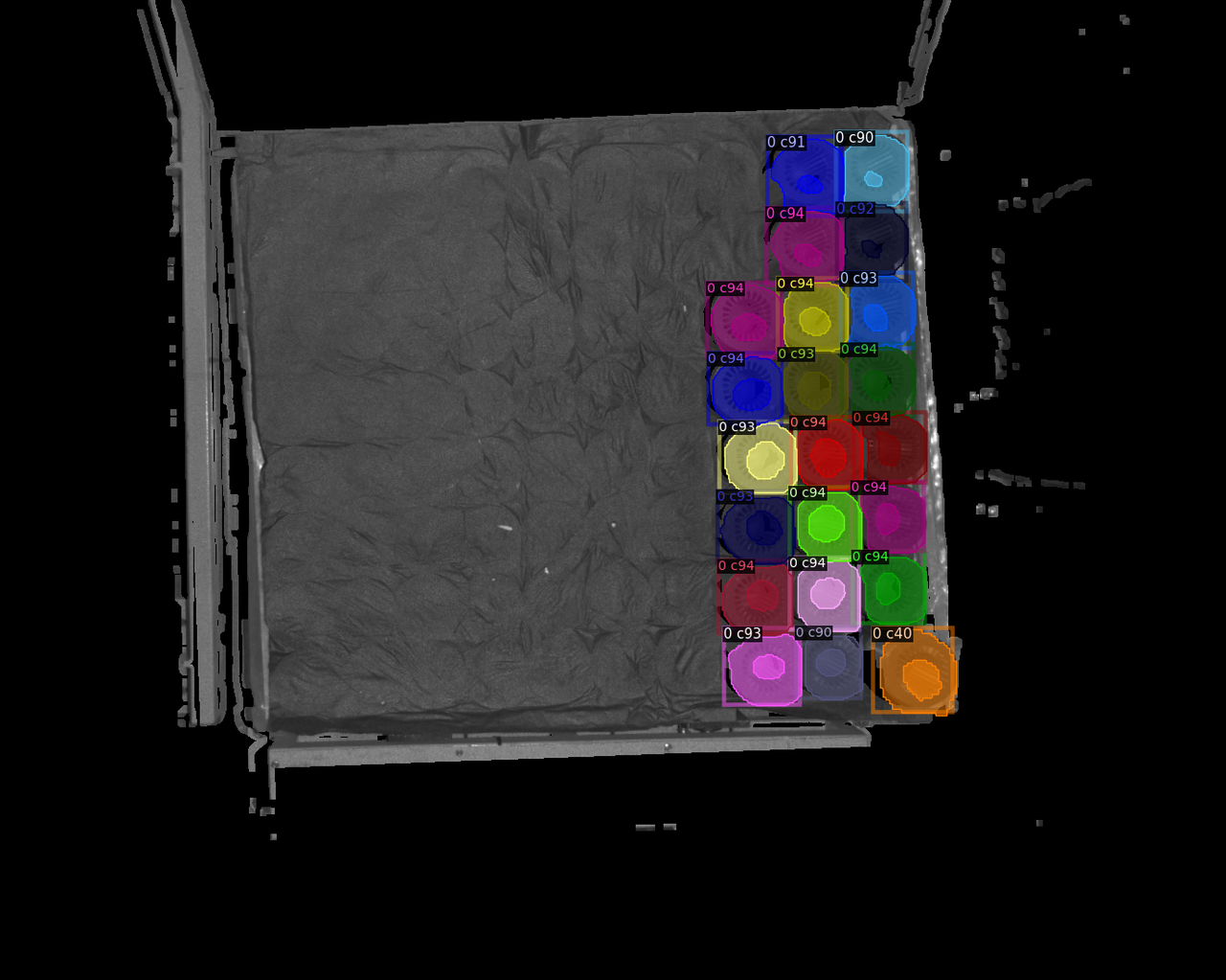 |
| 9 | 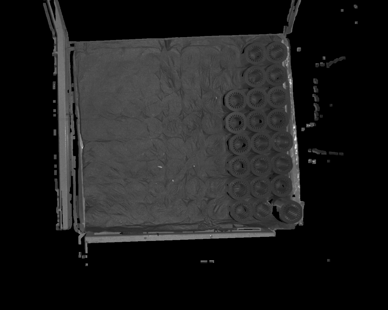 | 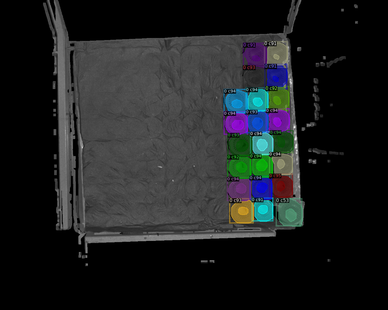 |
| 11 | 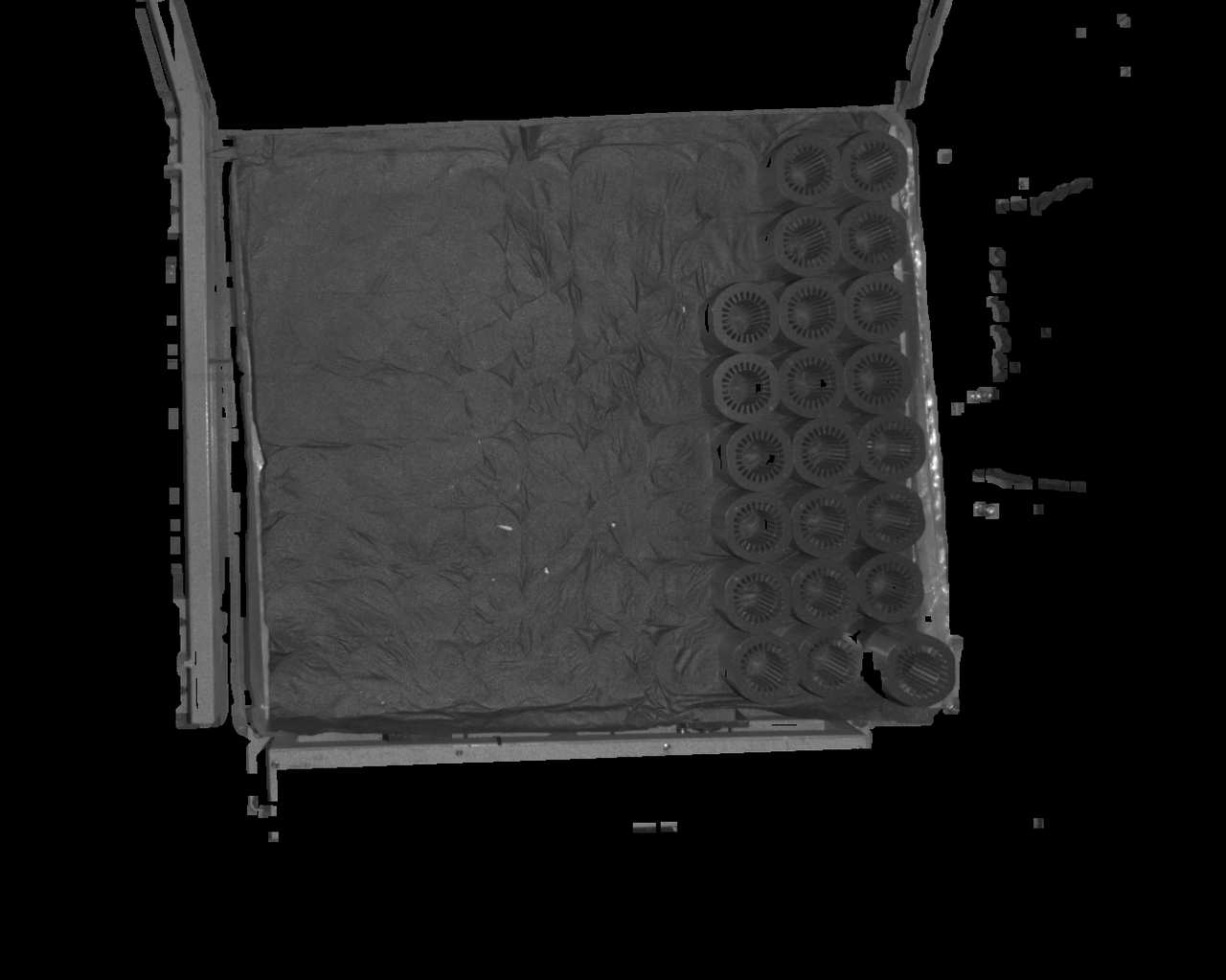 | 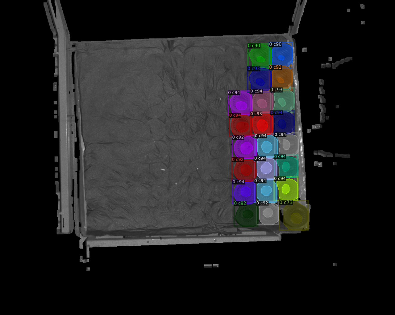 |
| 13 | 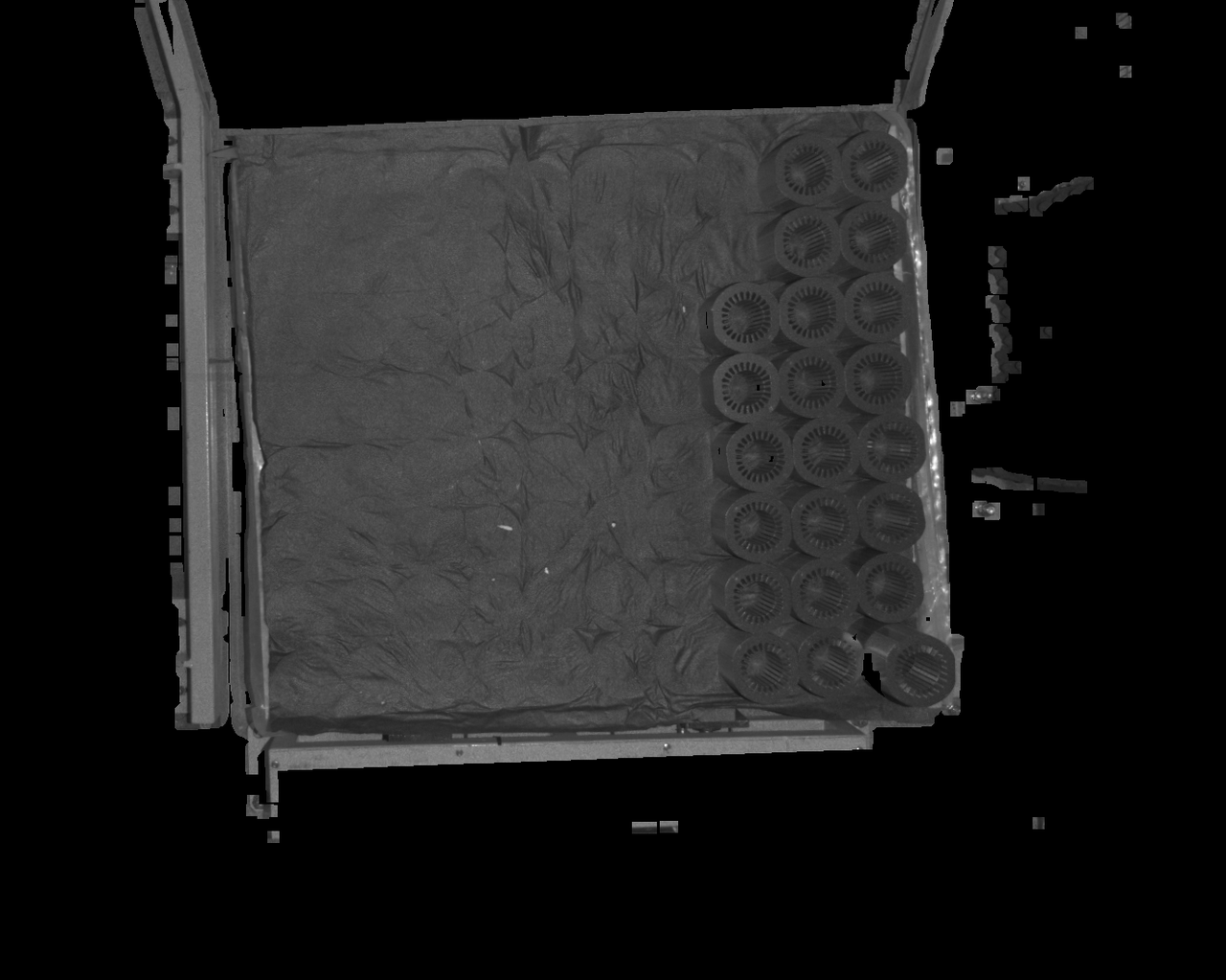 | 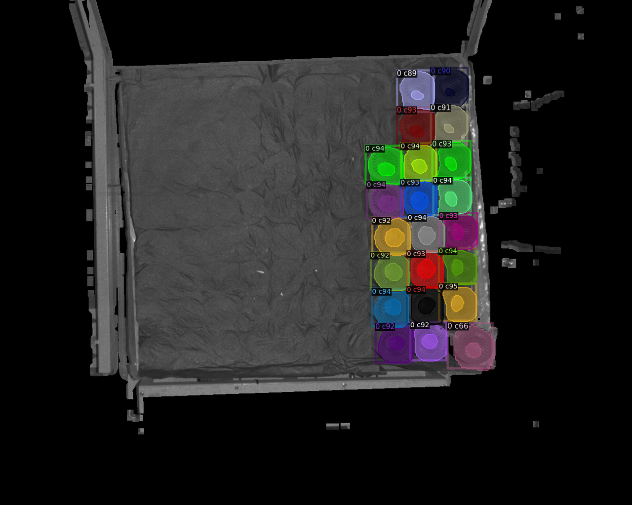 |
| 15 | 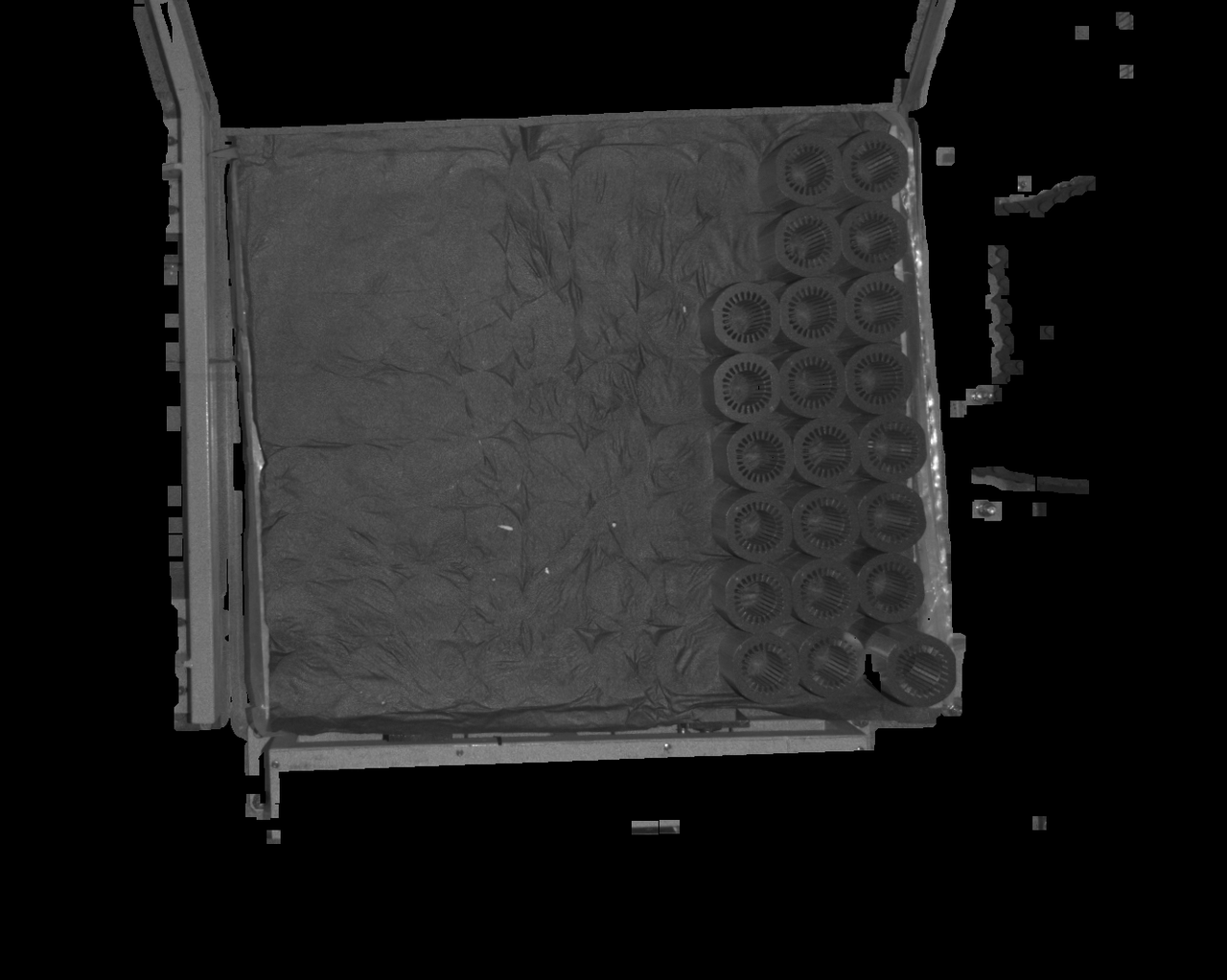 | 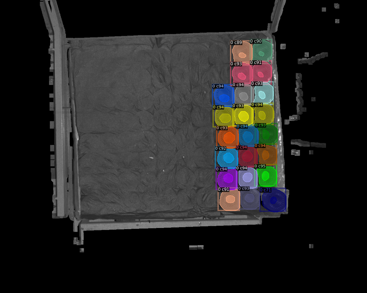 |
| 17 | 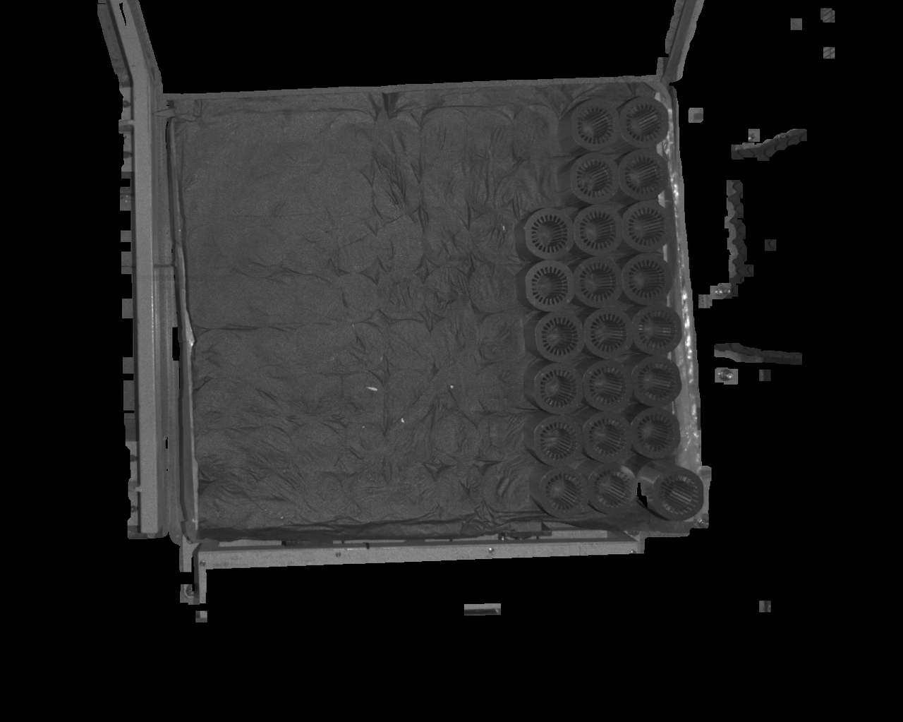 | 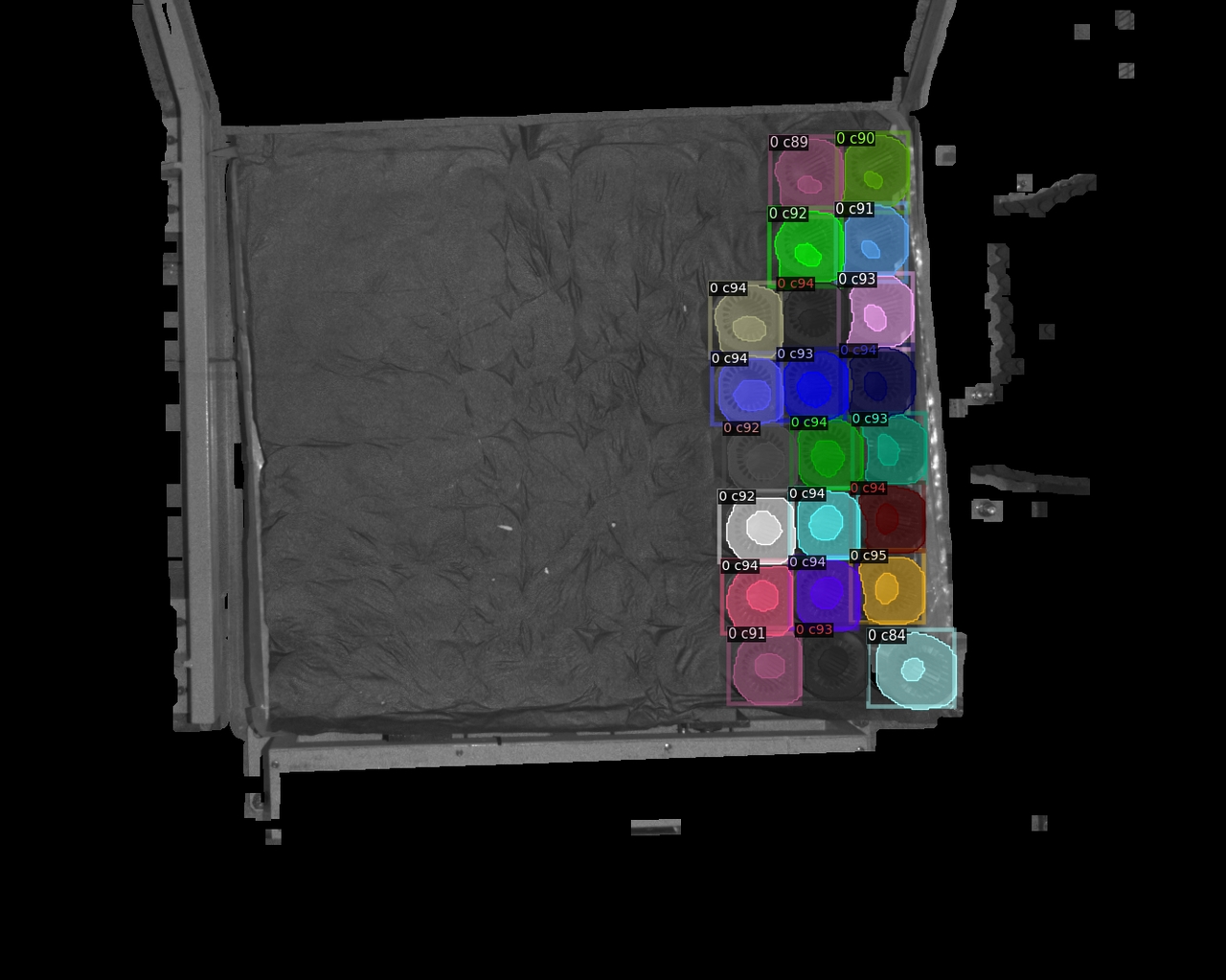 |
| 19 | 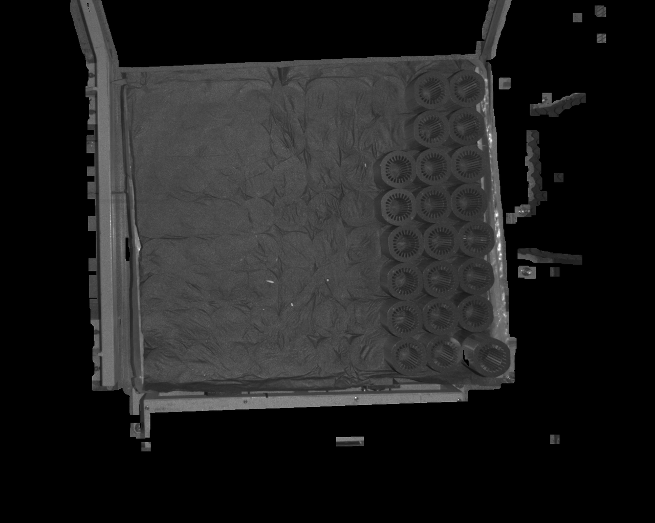 After increasing the fill kernel size, the black holes are greatly reduced in the detection area, improving detection results. | 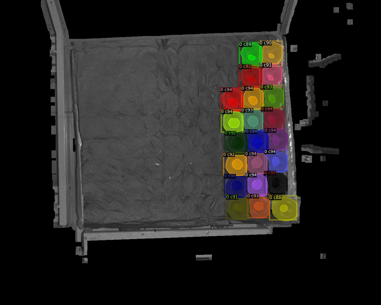 |
4.1.9 Model Fails to Detect Targets
Issue: After the upper layers have been picked, the deep learning model cannot detect the targets in the last remaining layer.
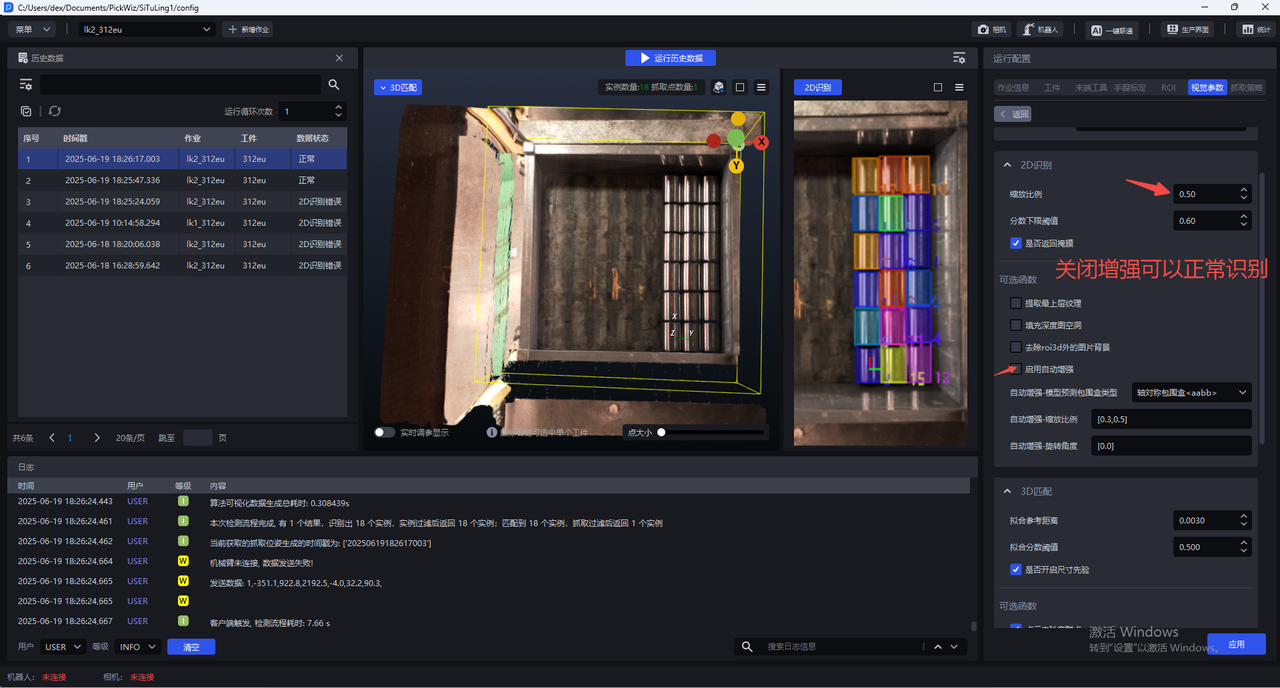
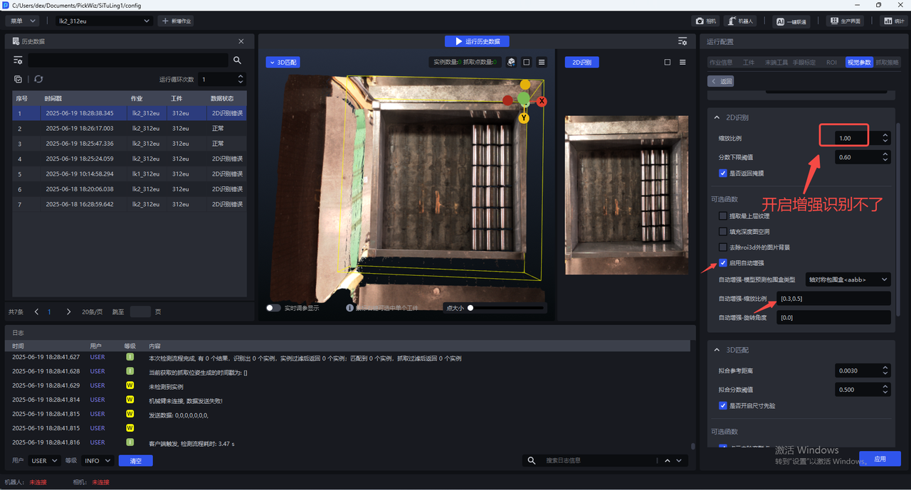
Affected version: 1.6.1
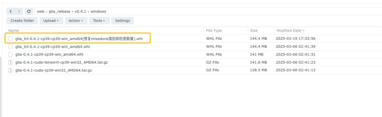
Possible cause: The installed glia version is glia 0.4.1, which is incompatible with the model.
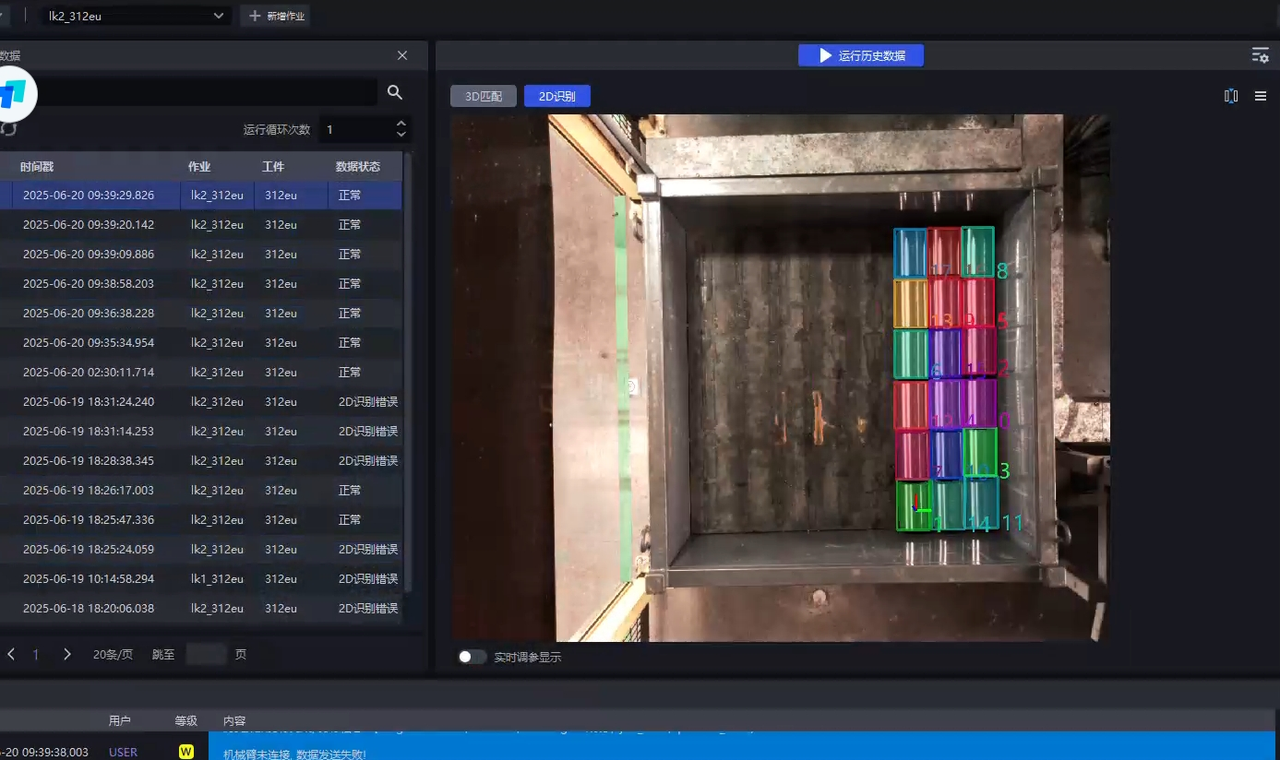
Solution: Download the patch package from the NAS system and update glia. The model can then detect the last layer.
4.2 CPFV
Point Cloud Matching Pose Estimation Configuration Guide
4.2.1 CPFV Returns No Detection Results
Problem: Detection fails, and CPFV returns no results.
Solution:
Check the template point cloud for noise points that do not belong to the target. Inspect it in MeshLab as shown. If the bounding box is larger than expected for the template point cloud, noise points remain.
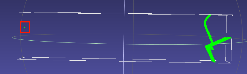
If the system reports that no pose was detected, first set bootstrap_percentage to 1. Once matching is accurate, consider downsampling and other parameters to reduce cycle time.
Check whether the number of points in the template point cloud is comparable to the scene instance point cloud (instancepcd) before downsampling. Using an undownsampled scene point cloud as the template is recommended. When downsampling the scene point cloud, apply corresponding downsampling to the point cloud used as input for pose estimation.
Check whether model_voxel matches the scene point cloud downsampling parameter in preprocessing.
Try reducing both model_voxel and the scene point cloud downsampling parameter in preprocessing to increase the number of points available for matching.
If the template and scene point clouds use the same downsampling settings and both contain 200+ points, but detection still fails, their normal vectors may differ. This is most likely when using contour mode; a fix was made in version 1.5.2. Open both point clouds in MeshLab and check whether their normal vectors are consistent. If they are highly consistent but detection still fails, contact the product and R&D team for support.
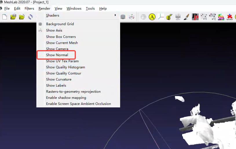
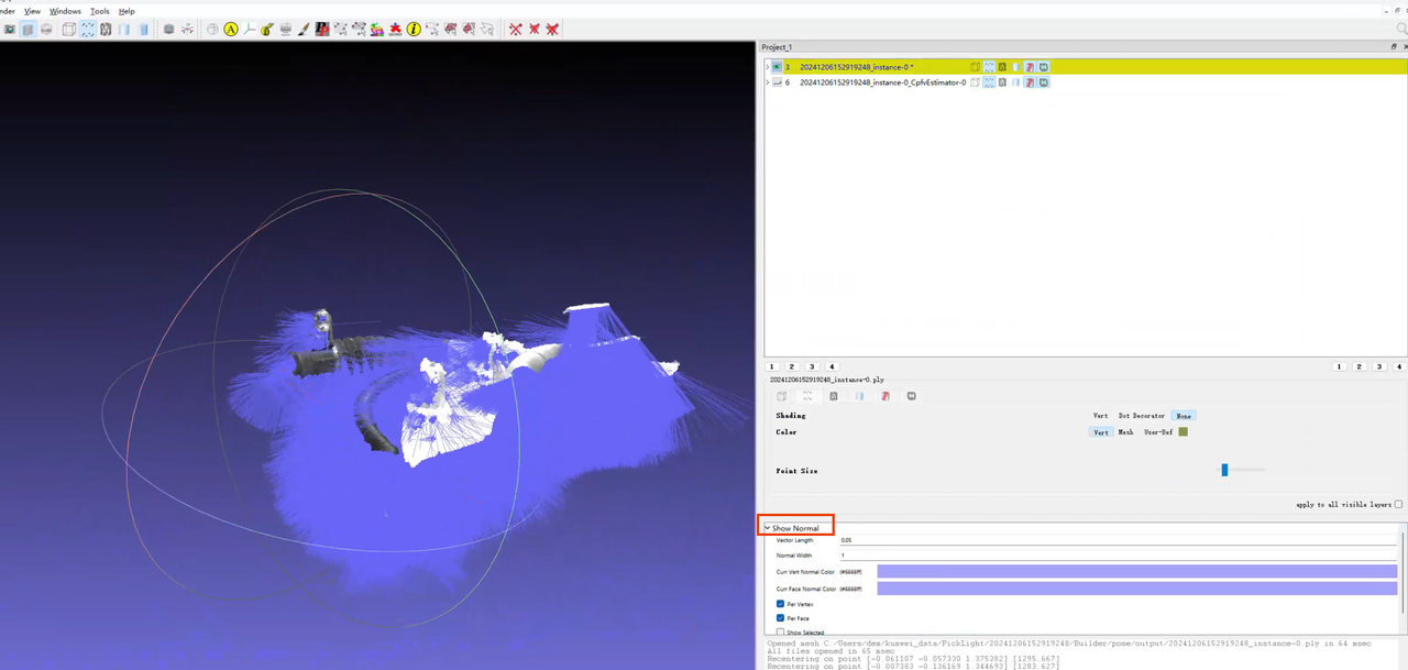
How to inspect point cloud normal vectors in MeshLab:
Drag in the point cloud file.
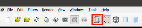
Select the point cloud whose normal vectors you want to inspect, then click render in the upper-left corner.
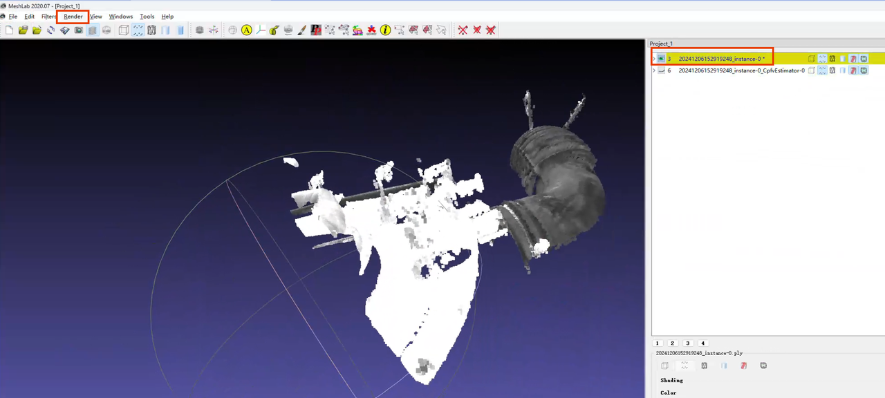
Click show normal in the render dropdown.
Set the color and size in the lower-right corner.
4.2.2 Poor Model Localization Accuracy/Poor Repeatability
Problem: Accuracy is poor; model localization accuracy or repeatability is poor.
Solution:
If matching is inaccurate, first set bootstrap_percentage to 1. Once matching is accurate, consider reducing cycle time.
Check whether a direction prior is configured. Test whether removing it helps.
For PickLight backend versions after 1.4.0, CPFV does not perform fine ICP registration by default. Check whether the pose estimation node has an icp_process postprocessing function. For usage, see the Point Cloud Matching Pose Estimation Configuration Guide
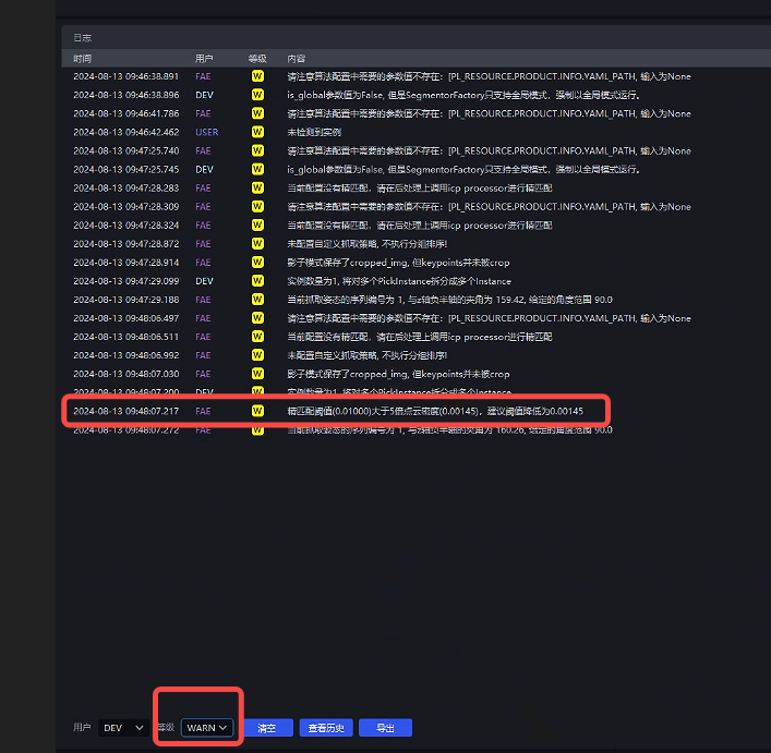
For software versions <= 1.4.2, note: When the icp_process postprocessing function is present, set its "save_data" parameter to true and inspect the pose estimation visualization in the pose_refine folder. The point cloud registration result in the existing Pose folder ≠ the final pose estimation result. Do not conclude that pose estimation is inaccurate based on the point cloud at that location.
For software versions >= 1.4.3, the ICP registration results are saved as two point cloud files with the suffix poserefine in Pose/output.
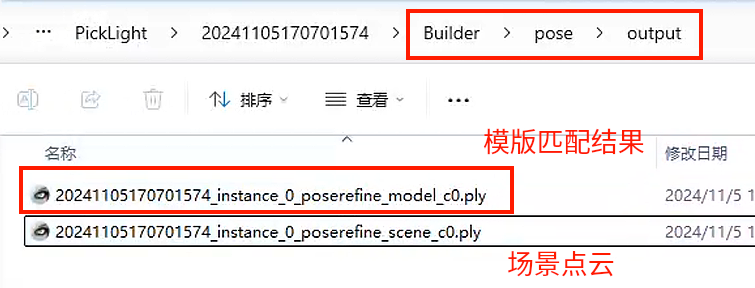
If the visualized accuracy after using the ICP function is still insufficient, try setting icp_mode="Plane" in the icp_process function.
When localizing a small target, reduce icp_dist=0.xxx in the icp_process function as indicated by the logs.
If repeated captures of the same scene produce different matching results, check whether the point clouds from those captures are consistent. Capturing from multiple angles may cause the spatial positions of key point cloud features to change.
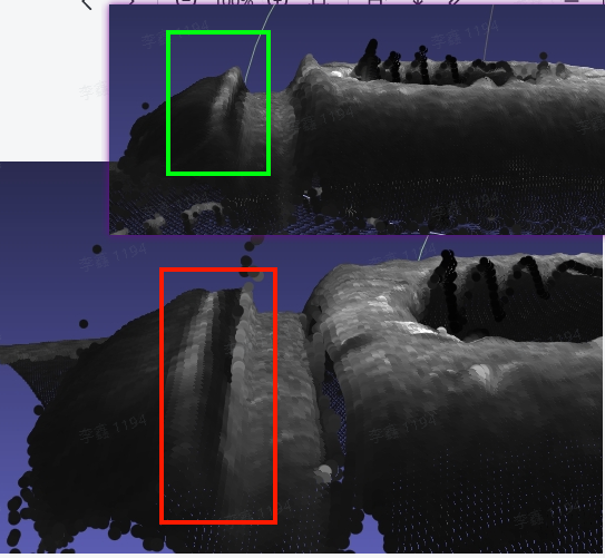
Inspect the point cloud template and remove noise points—parts that appear in some scene point clouds but not others.
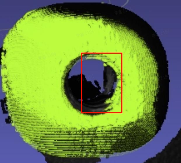
4.2.3 Model Localization Produces a Rotated Pose
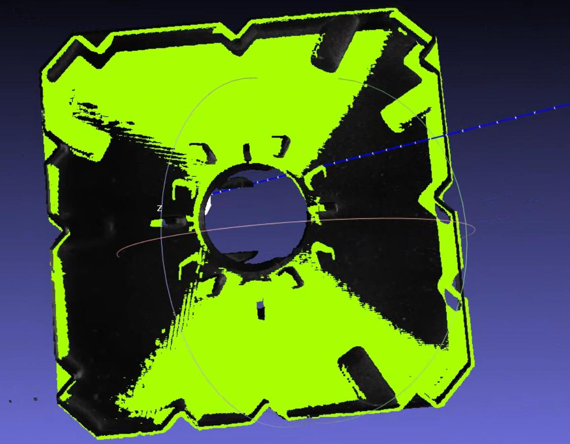
Problem: Angular accuracy is poor, or the application requires precise orientation, and model localization produces a rotated pose.
Solution:
For a rotationally symmetric target, the result may rotate 180 degrees around RZ. If incoming targets always have a consistent orientation, set the CPFV direction prior to [1,0,0,0] to keep registration consistent. If incoming target orientation is not consistently the same, do not add a prior. Instead, add the bound_euler_angle function. For a description of the function, see section 3.1 of Pick Strategy Adjustment Guide [To Be Updated].
- "prior_direction": [[1,0,0,0]]
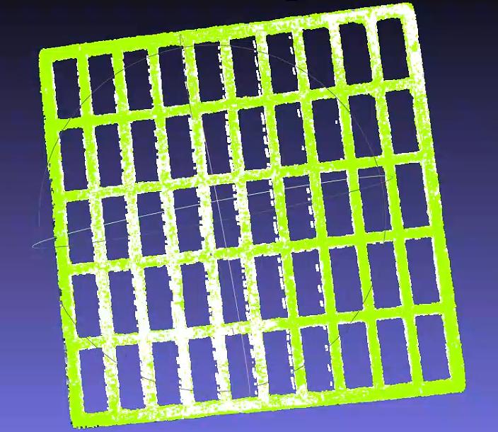
Add the refine_pose_by_z_axis_rotation function to the pick point generation node’s postprocessing section to correct the rotated pose (version 1.4.2 and later).

For guidance on the function parameters, see the Point Cloud Matching Pose Estimation Configuration Guide.
4.2.4 Registration Cycle Time Does Not Meet the Target
Problem: Cycle time is poor; registration takes longer than expected.
Note: CPFV cycle time is currently expected to be within 2 seconds (1 second for detection and 1 second for fine registration).
Solution: Adjust the following parameters only if matching accuracy remains acceptable. Test matching accuracy or inspect the visualization after each adjustment.
Check the detection time in the logs, as shown below. Detection time represents CPFV processing time. Treat pose estimation time minus detection time as postprocessing ICP time.


If CPFV takes too long:
Adjust the downsampling parameters so that both the template and scene point clouds in the reference data contain around 200 points. This generally works well.
bootstrap_percent5age ranges from 0 to 1. A value of 1 is slowest but most stable; 0.1 is fastest but least stable. Reduce it by 0.1 at a time. In general, do not reduce it below 0.3–0.5; lower values can cause occasional failures to detect a pose.
Check that relative_allowed_diam=0.04.
If postprocessing ICP takes too long:
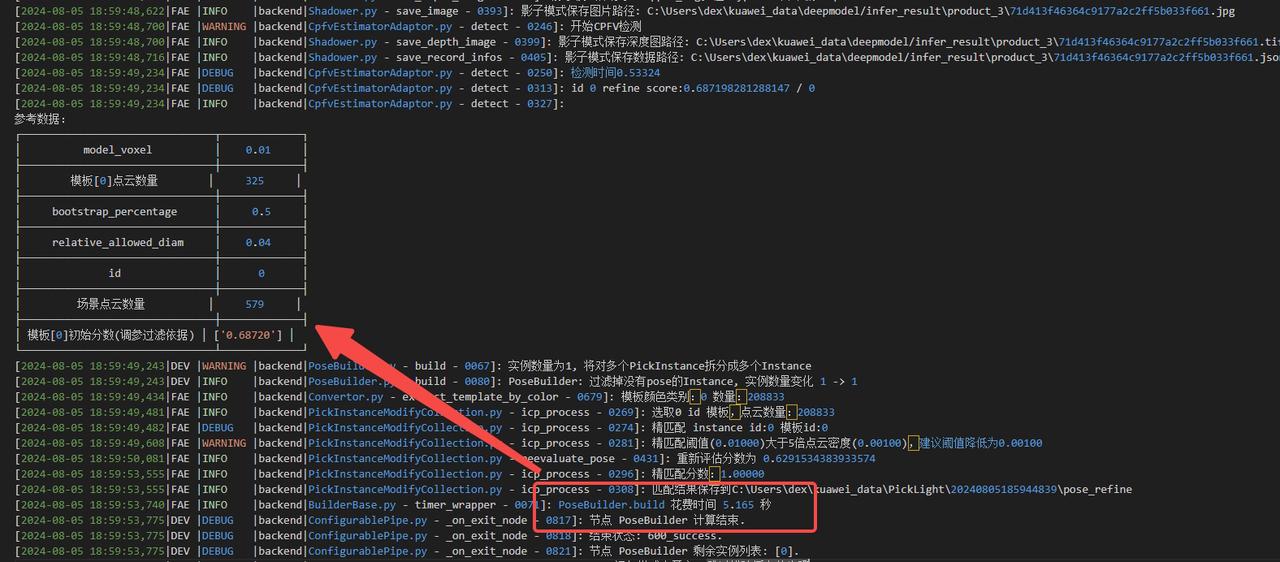
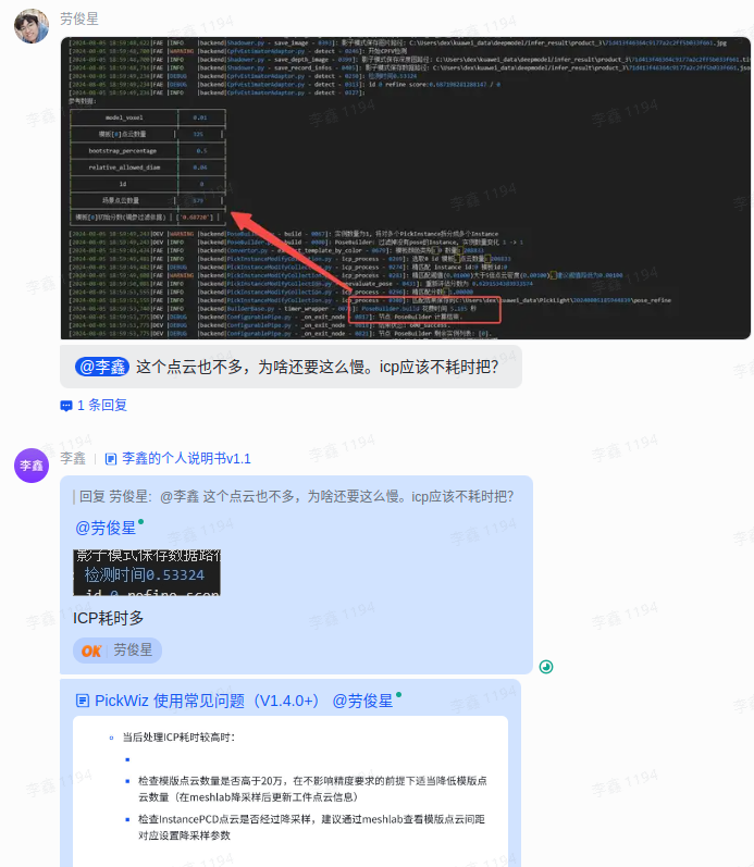
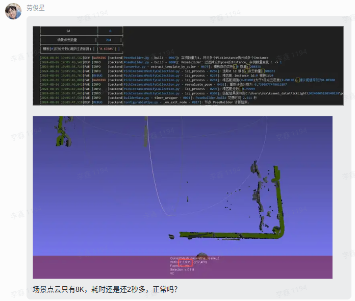
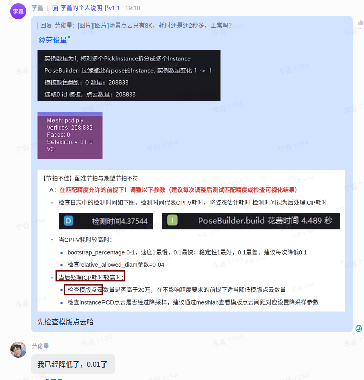
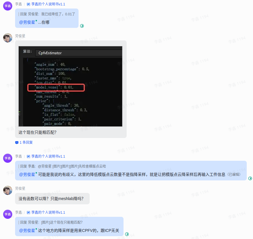
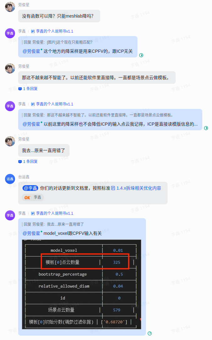
Check whether the template point cloud contains more than 200,000 points. If accuracy requirements allow, reduce its point count appropriately. After downsampling in MeshLab, update the target’s point cloud information.
Check whether the InstancePCD point cloud has been downsampled. Inspect the template point spacing in MeshLab and set the downsampling parameter accordingly.
4.2.5 Planar Target Matching Drifts or Slides
Problem: Matching is offset; registration of a planar target drifts or slides.
Solution: First determine whether the target point cloud dimensions change in any direction. If they do, identify the part of the main body that remains unchanged.
Create the template as shown, and enter the coarse registration template in the target properties.
Add the icp_process parameter mode_path="path to fine registration template file".
- For Windows paths, double backslashes or forward slashes are recommended.

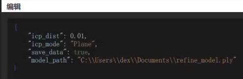
{
    "icp_dist": 0.01,
    "icp_mode": "Plane",
    "save_data": true,
    "model_path": "C:\\Users\\dex\\Documents\\refine_model.ply"
}
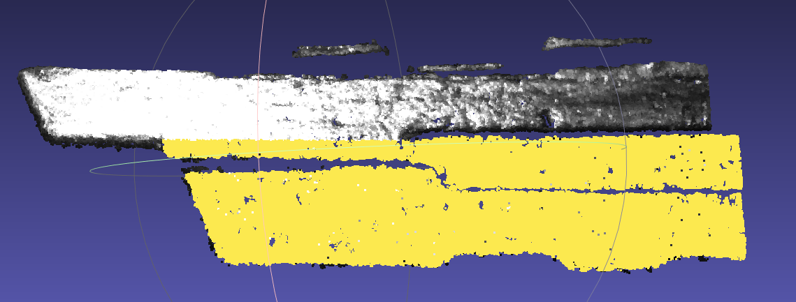
Scene point cloud (dimensions inside the red box vary) Coarse registration template (extending farther right than the scene is recommended) Fine registration template (use the unchanged region) 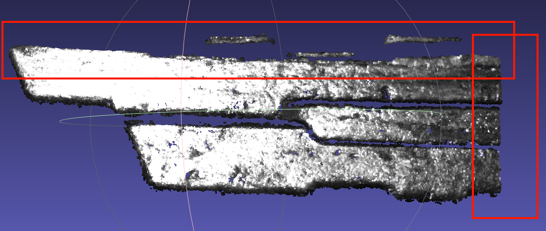
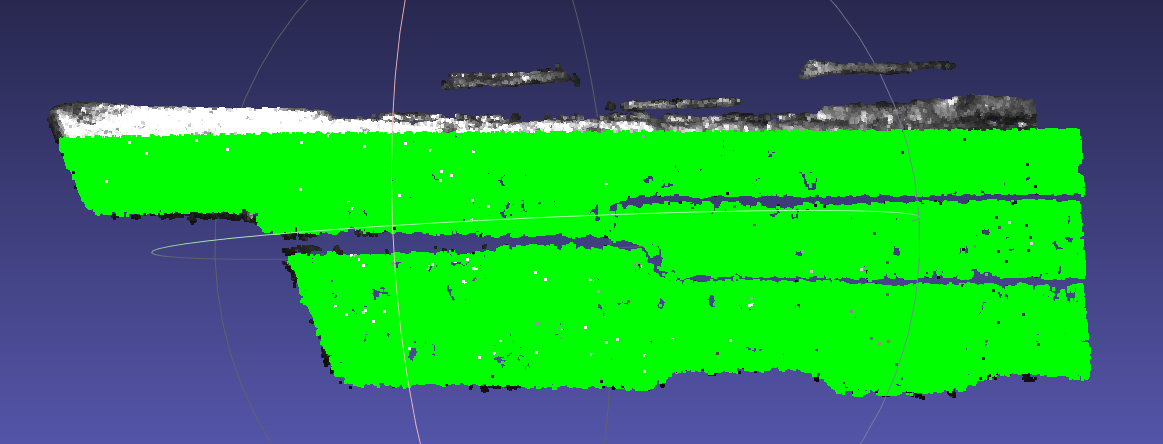
Add edge point extraction.
Add the get_boundary_points function to CPFV preprocessing.
{
    "angle_threshold": 90,
    "max_nn": 30,
    "radius": 0.005
}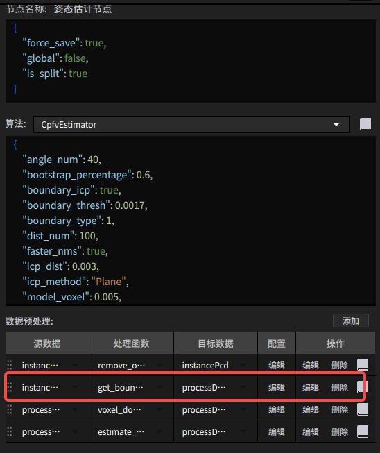
Warning! When using get_boundary_points, remember to change the downsampling input data type.
Add the boundary_type parameter to CPFV.
{
    "angle_num": 40,
    "bootstrap_percentage": 1.0,
    "boundary_type": 1,
    "dist_num": 100,
    "faster_nms": true,
    "icp_dist": 0.01,
    "icp_method": "Plane",
    "model_voxel": 0.005,
    "nms_thresh": 0.5,
    "num_results": 1,
    "prior": {
        "angle_thresh": 30,
        "distance_thresh": 0.3,
        "is_flat": false,
        "pair_criterion": 1,
        "pair_mode": 0,
        "prior_direction": []
    },
    "process_in_roi": true,
    "refine": true,
    "relative_allowed_diam": 0.04,
    "scene_ratio": 1,
    "score_thresh": 0.5,
    "update_prior": false
}
If a planar target still shows sliding offset after boundary_type is enabled, use contour refinement (currently available on branch cwy/add-boundary-refine and planned for a later merge into 1.4.x). Add the boundary_icp and boundary_thresh parameters.
Parameter descriptions:
When boundary_icp is true, contour refinement is enabled. The default is false.
boundary_thresh is the radius used to calculate the model contour. Its default is 0.005, matching the radius parameter of get_boundary_points in preprocessing. (The recommended contour radius is half the downsampling factor. Adjust it based on the template and scene contour point clouds in Builder/pose/input.)
{
    "angle_num": 40,
    "bootstrap_percentage": 1.0,
    "boundary_type": 1,
    "boundary_icp": true,
    "boundary_thresh": 0.005,
    "dist_num": 100,
    "faster_nms": true,
    "icp_dist": 0.01,
    "icp_method": "Plane",
    "model_voxel": 0.005,
    "nms_thresh": 0.5,
    "num_results": 1,
    "prior": {
        "angle_thresh": 30,
        "distance_thresh": 0.3,
        "is_flat": false,
        "pair_criterion": 1,
        "pair_mode": 0,
        "prior_direction": []
    },
    "process_in_roi": true,
    "refine": true,
    "relative_allowed_diam": 0.04,
    "scene_ratio": 1,
    "score_thresh": 0.5,
    "update_prior": false
}
4.2.6 Field Experience: Tuning Precise Localization for a Single Target
Project name: Suzhou Samsung – Locating screw holes on the bottom of a washing machine inner drum
Workflow characteristics
The Instance Segmentation node uses no algorithm. It selects part of the target solely through an ROI.
The target is registered and precisely localized using only CPFV+ICP.
Project requirements
Localization accuracy <=1 mm
Total processing time <=2 s
Proposed tuning process
Meet the localization accuracy requirement first, then reduce processing time. Refer to [Detection Failure] and [Poor Accuracy].
Tune the camera until point cloud quality is stable, then collect a dataset of scene point clouds with targets at different angles and positions within a fixed ROI.
Compare the scene dataset to identify feature regions that appear in every capture. Choose a relatively three-dimensional region as the point cloud template. For a planar target, contour registration is recommended.
Use the logs from actual operation to adjust scene point cloud downsampling and CPFV+ICP parameters until matching is stable.
Test localization repeatability. If it meets the requirement, localization tuning is complete; otherwise, continue adjusting the parameters.
Once localization accuracy meets the requirement, speed up CPFV+ICP.
Refer to [Poor Cycle Time].
If the pose estimation node takes around 1s but the total processing time still exceeds the target, analyze the cycle time. Then submit a request to the product and R&D team about other possible ways to speed it up.
Specific tuning issues and lessons
Issue 1: Matching offset and long processing time
The pose estimation matching result reported on site is shown below. Green is the matched template; white is the scene point cloud.
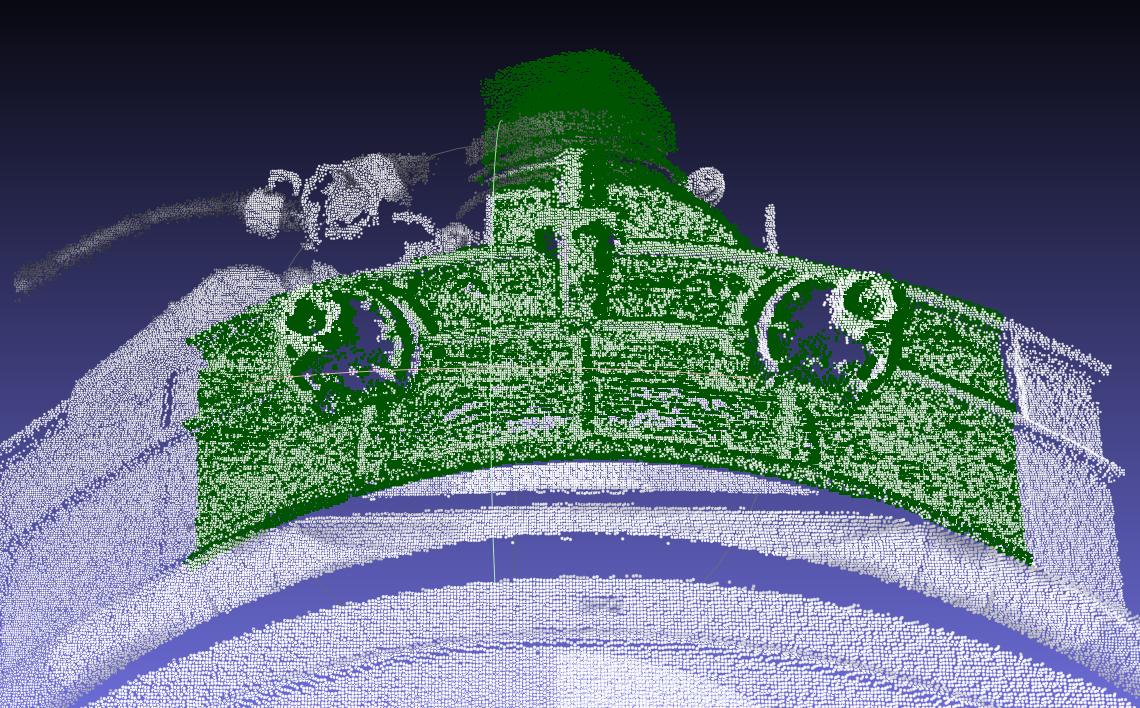
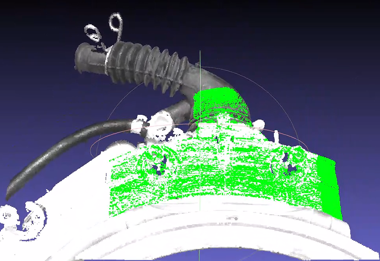
First, check how well the template and scene point clouds overlap.
A large part of the pipe body at the top of the image is missing from the scene point cloud.
The larger part of the target is the plane in the middle of the image, but similar planar point clouds appear on both sides of it.
Because the ROI’s position relative to the target is not fixed, the planar part of the template on one side may extend beyond the scene point cloud.
Identify the cause of the matching offset.
Because ICP matches pairs of points, the greater number of similar points can cause the head of the T-shaped template to “swing” left and right across the scene point cloud. The pipe body at the tail of the T cannot be effectively anchored by the scene point cloud, which may cause an offset.
Also, the icp_dis threshold defaults to 0.01. This causes the template point cloud to treat points within 10mm of itself as belonging to it, further increasing the variability of matching.
Solution 1:
Set icp_dis=0.002 to reduce variability in the template point cloud’s movement.
Adjust the point cloud template to remove the plane. Also add remove_or_preserve_plane to the Instance Filtering node’s postprocessing section to reduce the effect of missing planar points on matching. Configure the parameters as shown. A newly created function will also have a “return_params” parameter; delete it.
Set dist_thres according to the thickness of the variation in the planar point cloud.
Set inverse to true to remove the plane; otherwise, the plane is retained.
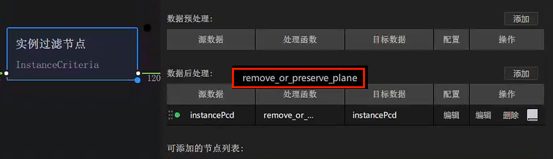
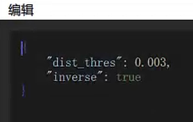
Create a new template from the point cloud with the plane removed.
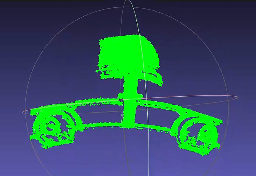
Adjust CPFV and preprocessing downsampling parameters to improve speed. Refer to [Poor Cycle Time].
Issue 2: Poor localization repeatability
The pose estimation result is severely misaligned.
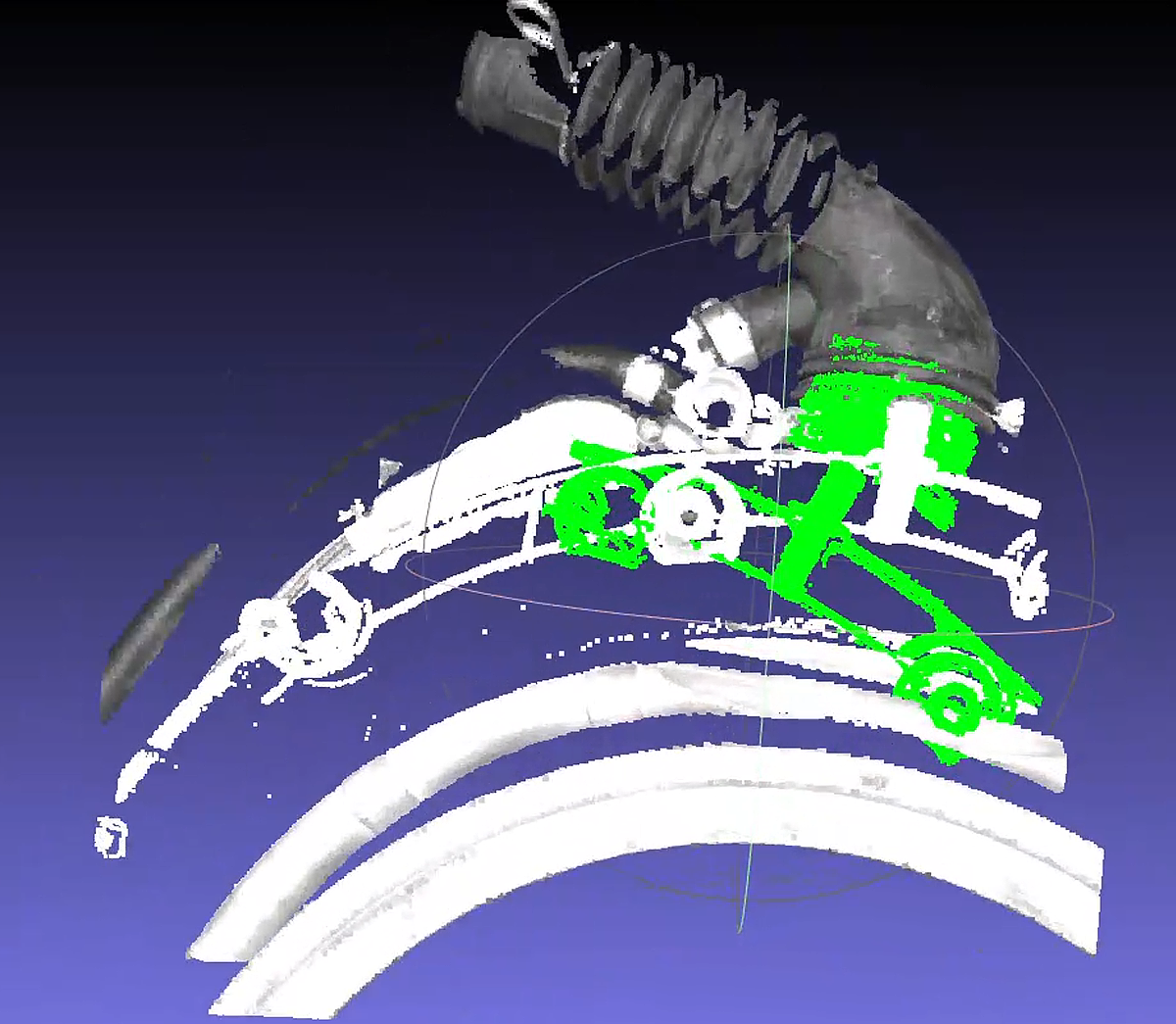
Inspect the coarse registration point clouds.
CPFV coarse registration with the new template may be very poor, preventing ICP from producing the correct result.
The spacing between points differs substantially between the template and scene point clouds. Inspection showed a large difference between model_voxel=0.01 and voxel_size=0.02.
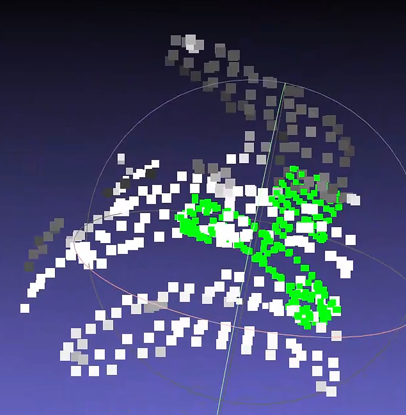
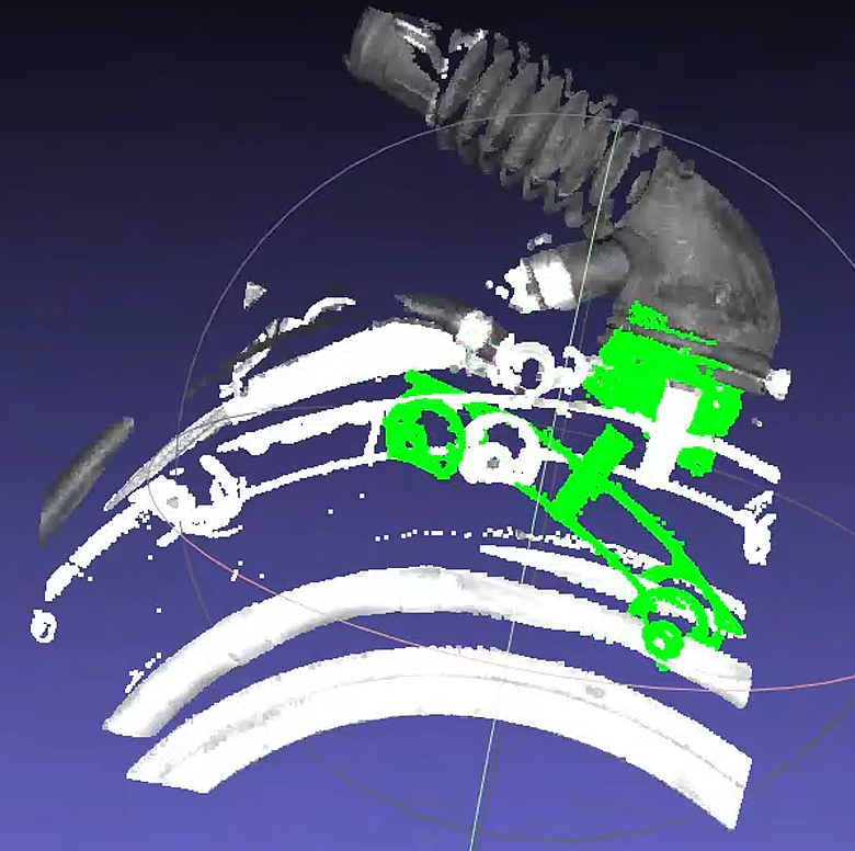
Solution 2:
- Set the preprocessing downsampling parameter to 0.015, bringing it closer to CPFV’s "model_voxel"=0.01.
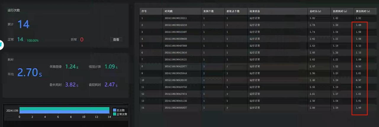
After this correction, all 13 historical datasets matched correctly. Ten captures with the on-site camera met the repeatability requirement, and algorithm processing time was around 1s.
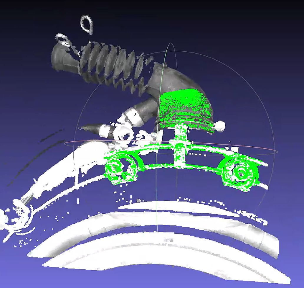
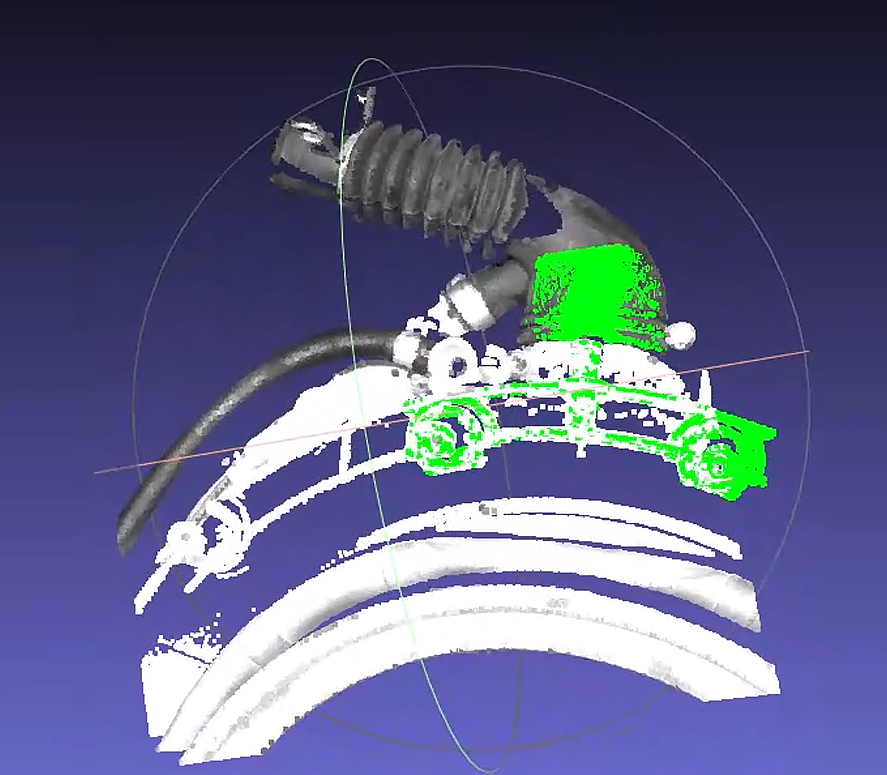
Note
The main feature in the new template changed from the plane to the front end of the black pipe. This part must remain inside the ROI regardless of the incoming target’s orientation; otherwise, matching may still be offset.
4.3 PNP
4.3.1 Inaccurate or Reversed Matching
Problem: Matching is inaccurate or reversed.
Solution:
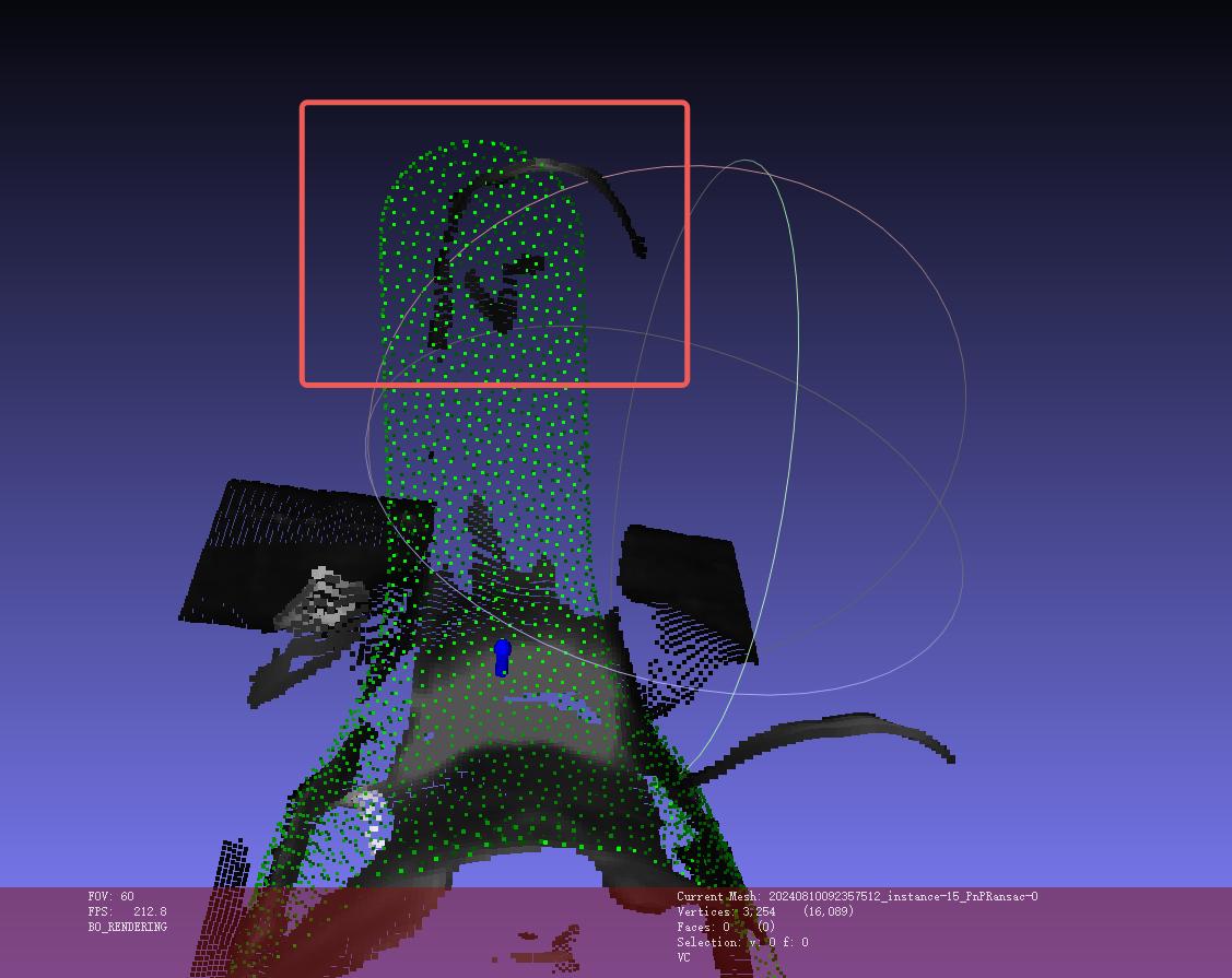
Inspect the template point cloud and remove interfering points.
Check whether the template point cloud is rotated 180° relative to the scene point cloud. If so, rotate the template point cloud 180°.
 |
  |
|---|
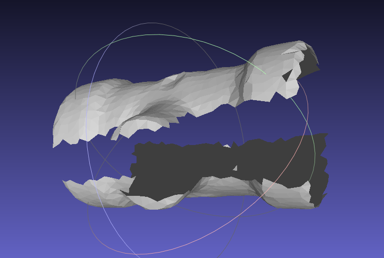
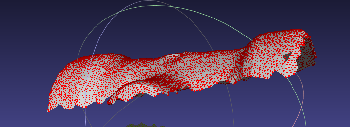
4.3.2 Matching Offset
Problem: In CAD-based picking of randomly arranged targets, pose matching with the SpatialRansac algorithm is offset.
Solution:
- Use a plane-type target with the cpfv algorithm. Obtain the model point cloud file by capturing an image with the camera and extracting the target.
If matching remains inaccurate after switching to cpfv, try the following:
Adjust the camera parameters to obtain a high-quality point cloud image.
Process the point cloud image produced by instance segmentation and use it as the point cloud template.
Adjust the numbers of points in the template and scene point clouds so that each contains 200~400 points.
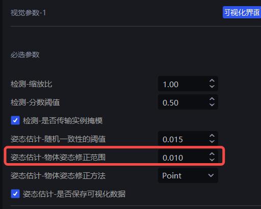
Set the bootstrap_percentage parameter to 1 to disable the pose-angle prior for pose estimation.
4.4 Cylinder Fitting PMFE
4.4.1 Pick Point Angle Is Not Perpendicular
Problem: How can the Z-axis pick angle be kept close to what appears perpendicular to the human eye?
Solution: Reduce the rotation interval in the cylindrical target properties. This places pick points at smaller angular intervals around the cylinder, making them denser. As a result, the angle between the most perpendicular pick point and the ROI Z-axis or camera Z-axis becomes smaller, as shown below:
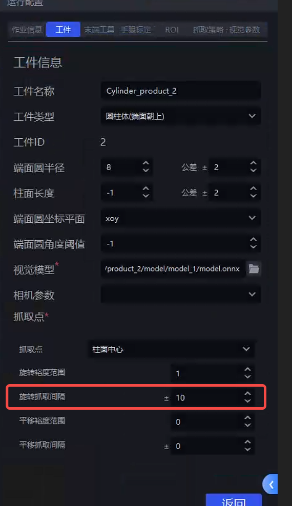
4.4.2 Fitted Pick Point Is Not at the Center of the Cylinder
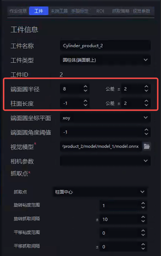
Problem: How can the pick point be placed at the center of the cylinder?
Solution: Set the radius prior and length prior in the cylindrical target properties, as shown below (units: mm).
4.5 Classification
4.5.1 Add Orientation Classification for a Cylinder
Problem: How can orientation classification be added for a new type of cylinder?
Solution: For a new Target type, add front/back orientation classification:
- To classify individual instances by front/back orientation, add the processor deep_feature_classify under Pick Point Generation → Post-processing, with the following parameters:
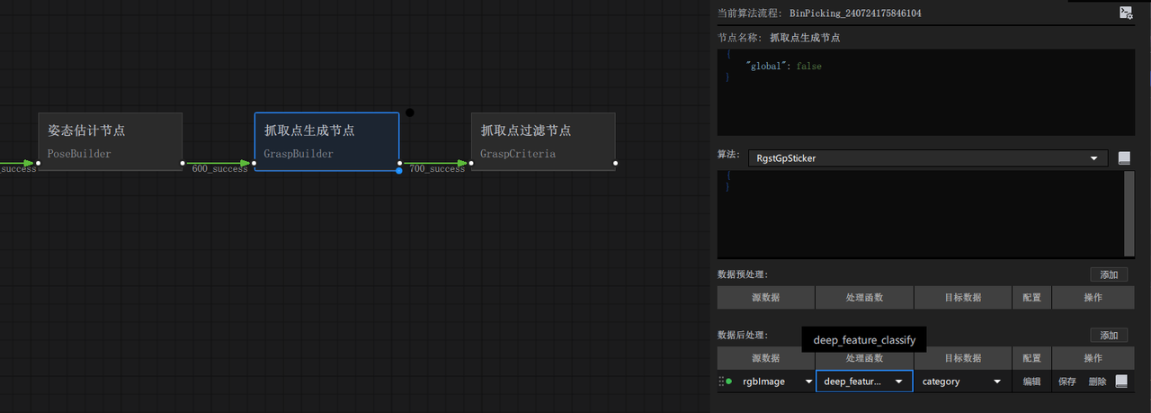
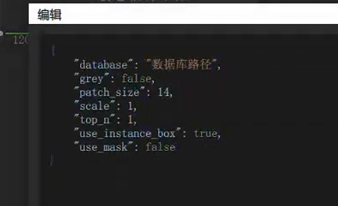
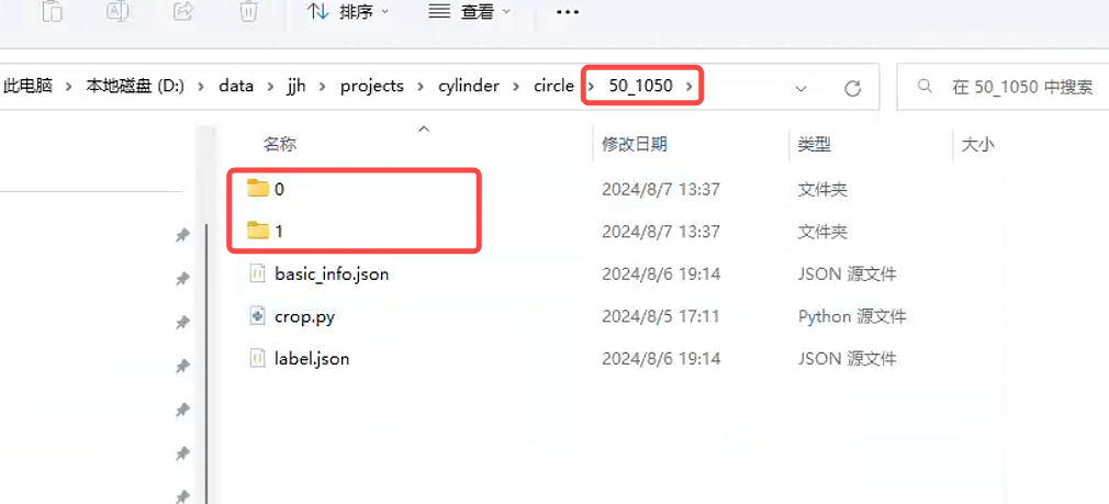
- Create a folder for the front/back data. Inside it, create two folders named "0" and "1", as shown below.
Run the workflow. Calling deep_feature_classify automatically crops the front/back images and saves them in the historical data.
View the latest historical data in picklight.
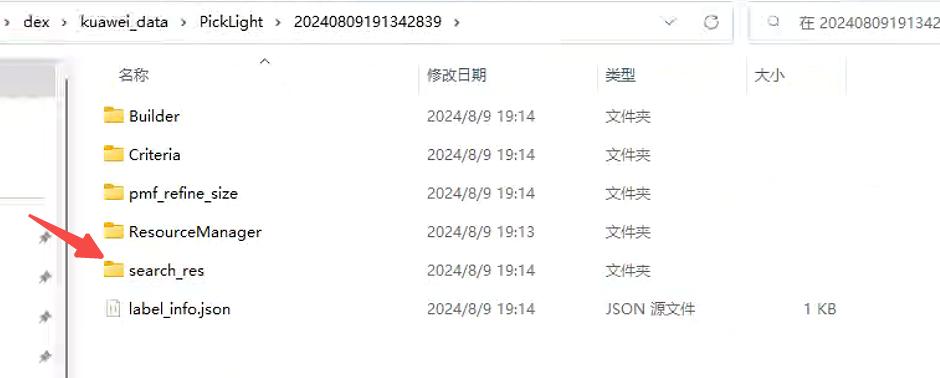
- Copy x_search.png. At the specified path, create a folder named for the size of the Target type you want to add. Copying an existing folder is easiest: keep its
0and1subfolders, remove any images already inside them, then place the images classified by orientation into the corresponding folders. (Tip: The operator must identify the front and back orientations in this step.)
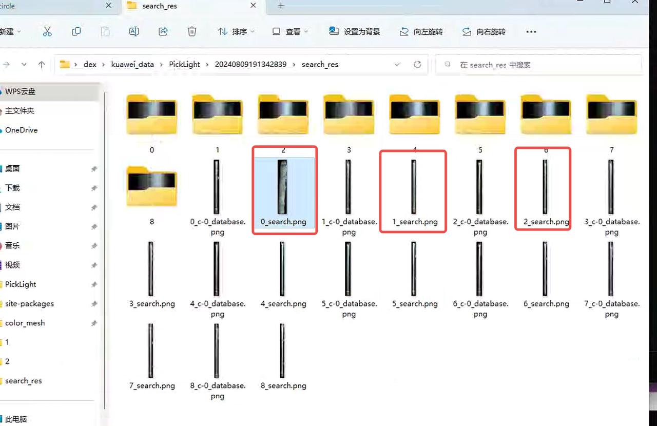
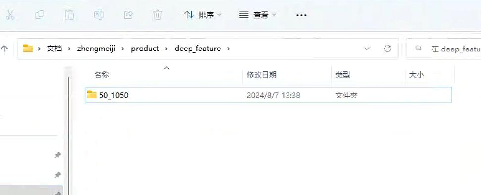
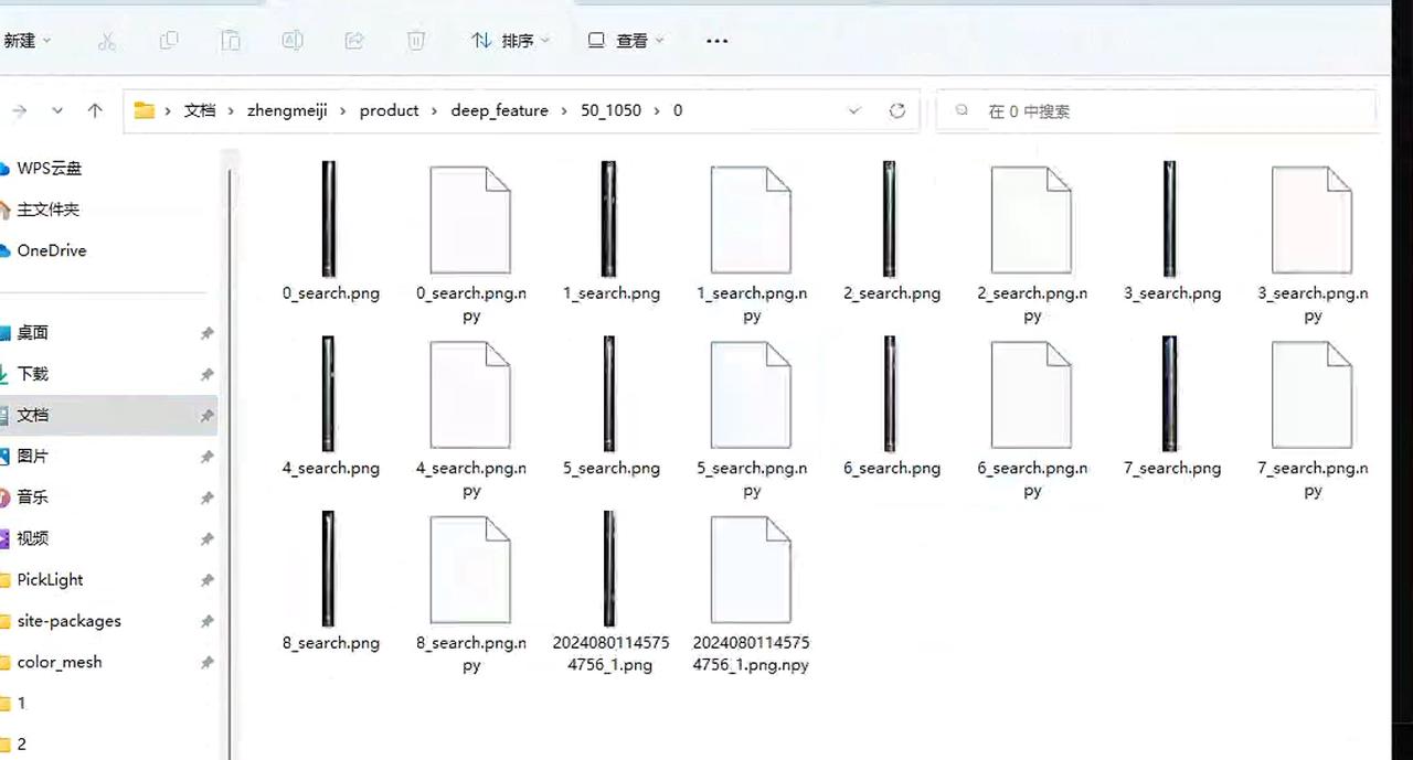
- Run these two commands at this path. Change the path to that of the Target type you are adding; this creates the front/back templates. (To find the path, open the folder named ‘新建文件夹2’ on the desktop, open the “site-packages” folder on the left, then create folders along the path shown in the image.)
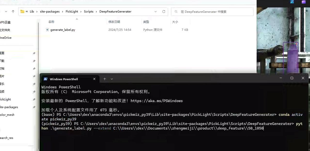
- To add another Target type, repeat the procedure starting from step 2.
4.6 Wire Harness Workflow
4.6.1 Camera Configuration
Adjust the 2d exposure. It needs to be high enough that the wire harness does not appear “completely black”.
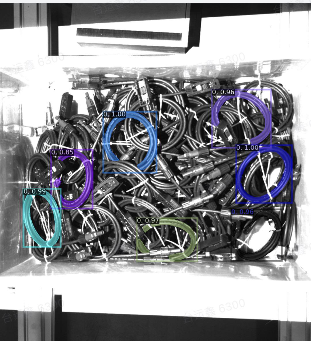
4.6.2 Target Template
Use the extracted point cloud as the template and align it with the keypoints, mesh, and other data. This can be done in meshlab.
O-shaped wire harnesses generally vary in size. You can scale both the Cad model and the feature points; see Common Meshlab Operations. Create a model that matches the actual wire harness size and register it in the software.
4.6.3 Bin Detection
Extract the bin opening precisely.
Keep track of where the point clouds are stored; bin templates for different workstations are independent.
Check backend.log in the backend logs. Search for
容器分数(“container score”) and verify that the matching score is normal (generally above 0.3–0.4).Use Points as the matching mode.
Add processing for materials that do not extend beyond the bin opening.
In the container node’s output, the suffix icp indicates the final bin-opening matching result; init indicates the initial bin-opening pose.
For detailed usage instructions, see Circle3D, IcpEstimator, and CPFV Parameter Descriptions.
4.6.4 Pose Estimation
For this wire harness scenario, use Points as the matching mode.
After changing the camera exposure, remember to adjust the Processor. Color filtering may otherwise filter the point cloud incorrectly.
The wire harness uses the dedicated branch cwy/collection_add_collision_score(only for version 1.2.x; not required for version 1.4.x). To prevent an empty-bin result during picking, set fitness to 0.
4.6.5 Collision Detection
Apply special handling when configuring the gripper; otherwise, it may grip the bin wall.
Set the bin height appropriately; otherwise, false collision detections may prevent materials at the bottom of the bin from being picked.
If the gripper grazes the bin, determine whether the cause is positioning or gripper dimensions. The gripper can be enlarged; see Common Meshlab Operations.
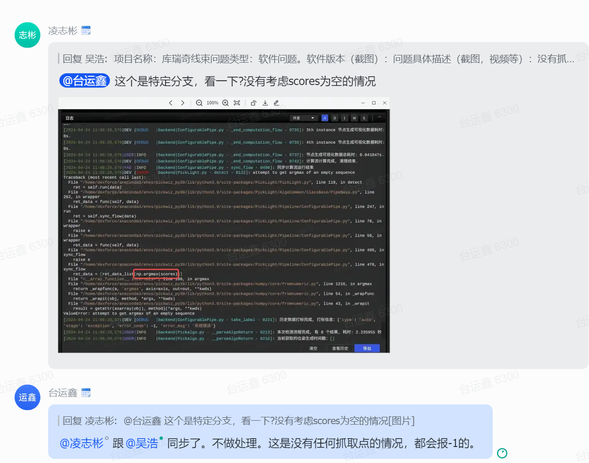
4.6.6 No Pick Points
4.6.7 Pick Point Settings
For the x and y axes, place the gripper coordinate system at the center of the wire harness point cloud.
For the z axis, place it on the point cloud surface, neither too high nor too low.
Set the rz angle correctly to match the actual gripping pose.
Set the rx and ry orientations perpendicular to the point cloud.
With an offset gripper, collision detection filters out many Pick Points. Configure symmetric Pick Points to work around collision-detection filtering.
4.7 Pick Ordering
4.7.1 Unexpected Ordering: Targets Are Not Picked in the Expected Order
Solution:
- Check whether instance filtering has reduced the number of instances included in pick ordering. All instances must be included to obtain the correct pick order.
4.7.2 Pick Strategy: Picking from a Lower Layer
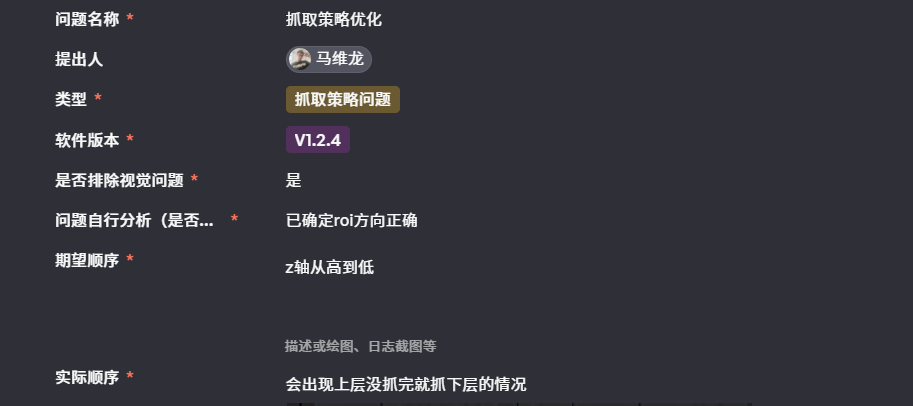
Solution: Troubleshoot in the following order:
Use the visualization from the Instance Generation node to determine whether the upper-layer instances were segmented correctly.
Identify the node that generates the instance point clouds. The height-based pick strategy runs after this node.
If the pick strategy runs before instance filtering, it orders the existing instances correctly. However, the Instance Filtering node may then remove some upper-layer instances (for example, because their confidence is low). Those upper-layer instances will not appear in subsequent results, making the system appear to pick from a lower layer.
Remove unnecessary filtering functions; train a new model in shadow mode.