
FINCH Camera Tuning Guide
This guide uses PickWiz 1.9.0 to explain how to connect, configure, calibrate the accuracy of, and tune imaging parameters for FINCH series cameras.
First, connect the camera to power and the network. For hardware installation, see the FINCH Series Camera Hardware Installation Manual. For models and specifications, see Available Cameras and Product Information.
1. Connect the Camera
Before starting, make sure the FINCH camera is connected to power and the network, and PickWiz is running.
1.1 Open the Camera Page
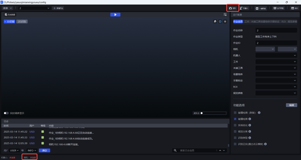
Open the “Camera” panel on the PickWiz main screen to go to the camera connection page.
1.2 Search for FINCH Cameras
On the camera connection page, select “FINCH” as the camera brand and click “Refresh” or “Search”. The software scans the current network for discoverable FINCH cameras and displays their IP addresses and connection status.
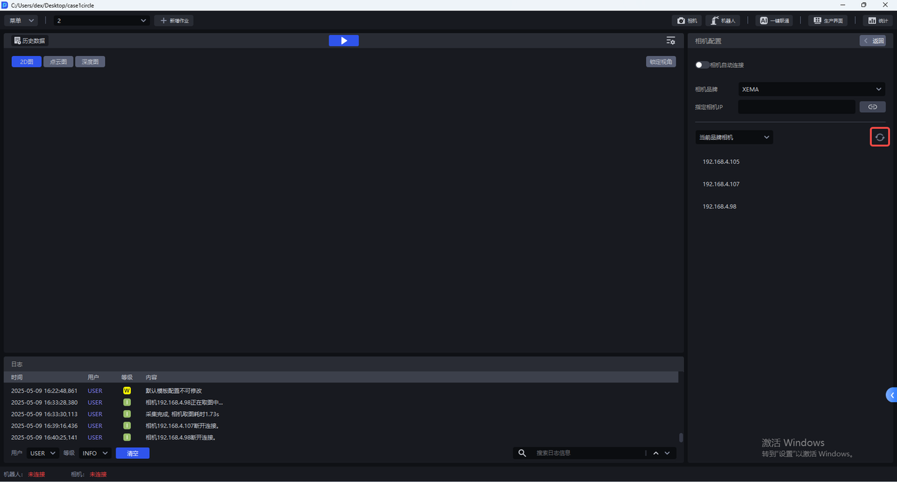
Find the camera you want to use in the search results, and check its IP address and device information.
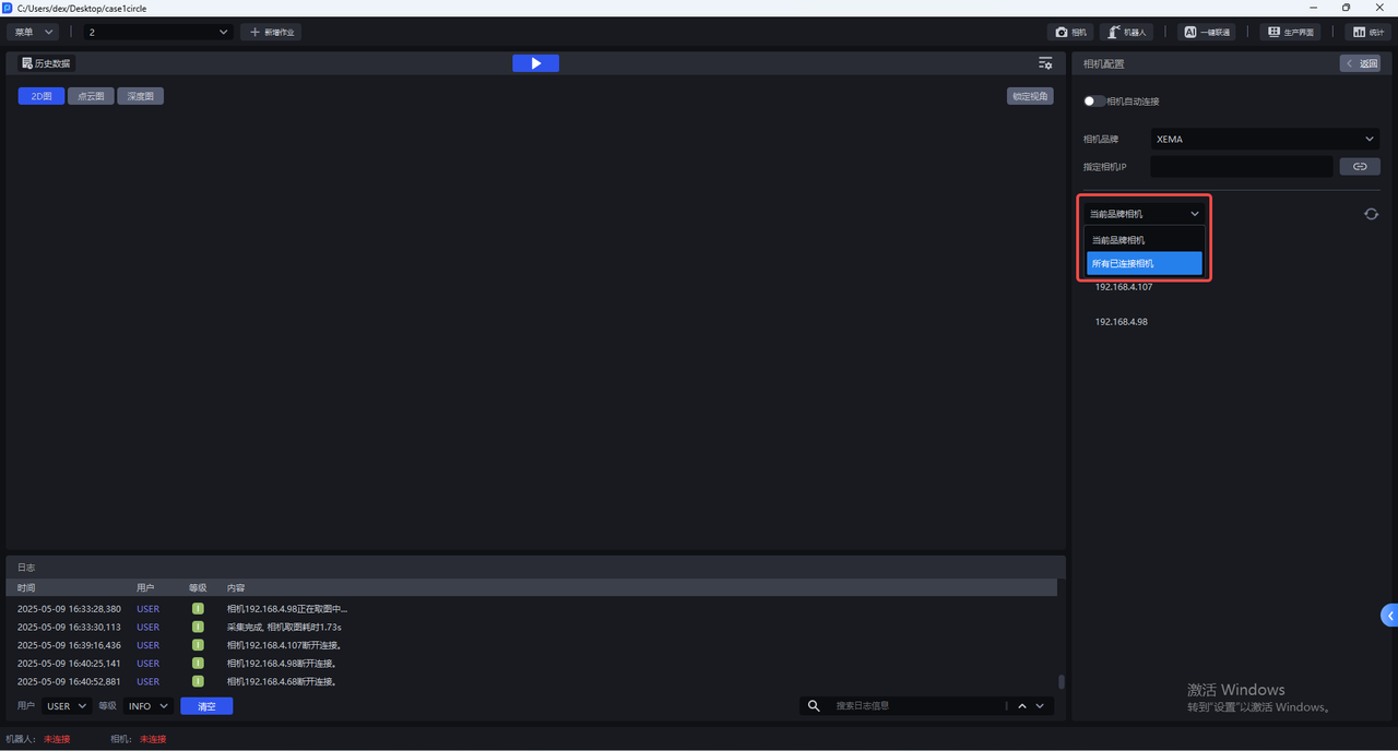
After confirming that the device information is correct, connect to the corresponding FINCH camera.
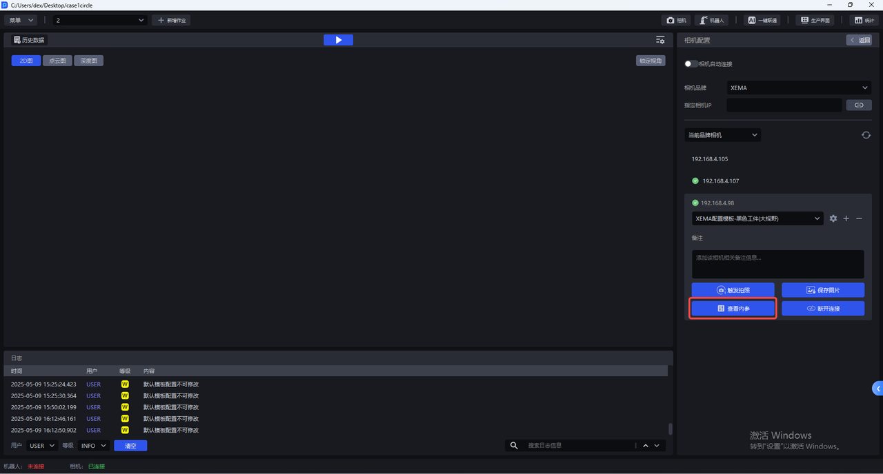
1.3 Connect Using an IP Address
If the search does not find the camera, or if you need to connect to a specific device, enter the camera’s IP address in the IP address field and click “Connect Camera”.
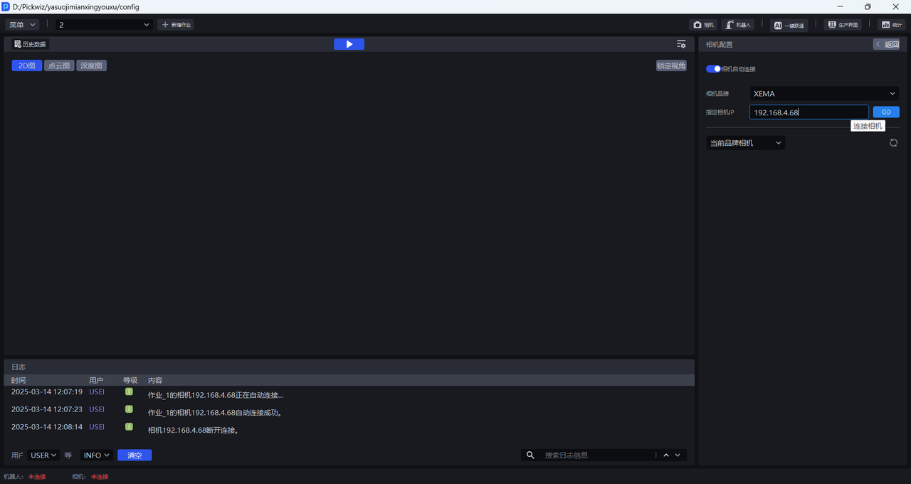
1.4 Select the Camera for the Current Task
After the camera connects successfully, go to the “Task Information” page and select the connected FINCH camera in the camera selection field for the current task.
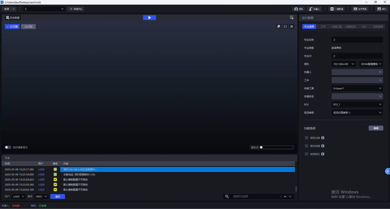
1.5 Confirm the Connection Status
After selecting the camera, check its connection status in the status bar. You can go to the camera configuration page to capture images and tune parameters only after the status shows “Connected”.
Caution
If the status does not show “Connected”, check the camera power supply, network cable connection, computer network configuration, and IP address before searching or connecting again.
2. Camera Configuration
A camera configuration stores a set of capture and imaging parameters. After connecting the camera, you can first select a default configuration to check the imaging results. To adjust parameters, copy a default configuration and edit the new configuration.
2.1 Select a Camera Configuration
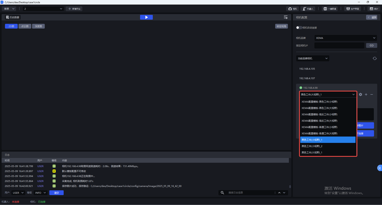
Find the connected FINCH camera on the “Camera” page, expand the configuration list, and select a default configuration suitable for the current target.
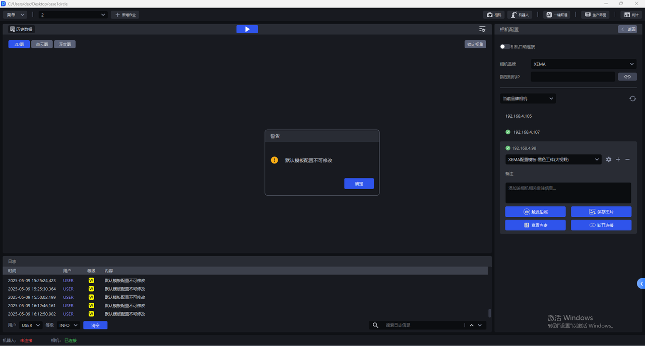
Default configurations cannot be modified. To adjust their parameters, first copy a configuration as described in Section 2.2.
Click “Trigger Capture” to capture a 2D image, point cloud, and depth image with the selected configuration. Check the imaging results in the visualization window.
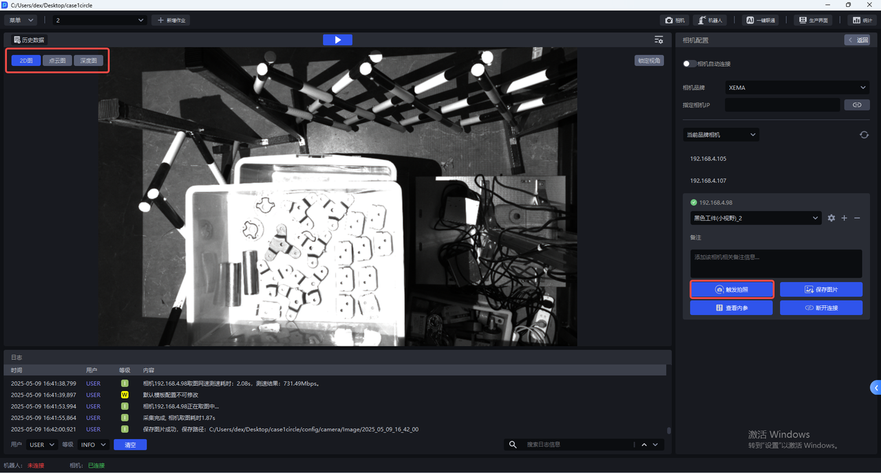
Use the following examples to judge whether the 2D image exposure is appropriate:
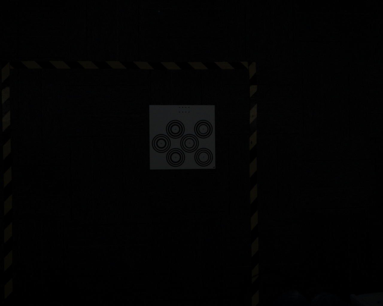 | 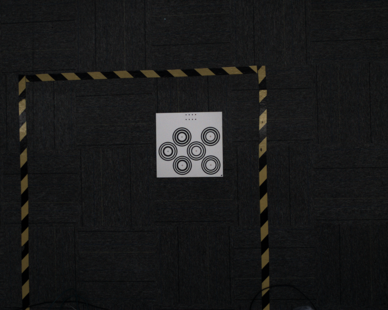 | 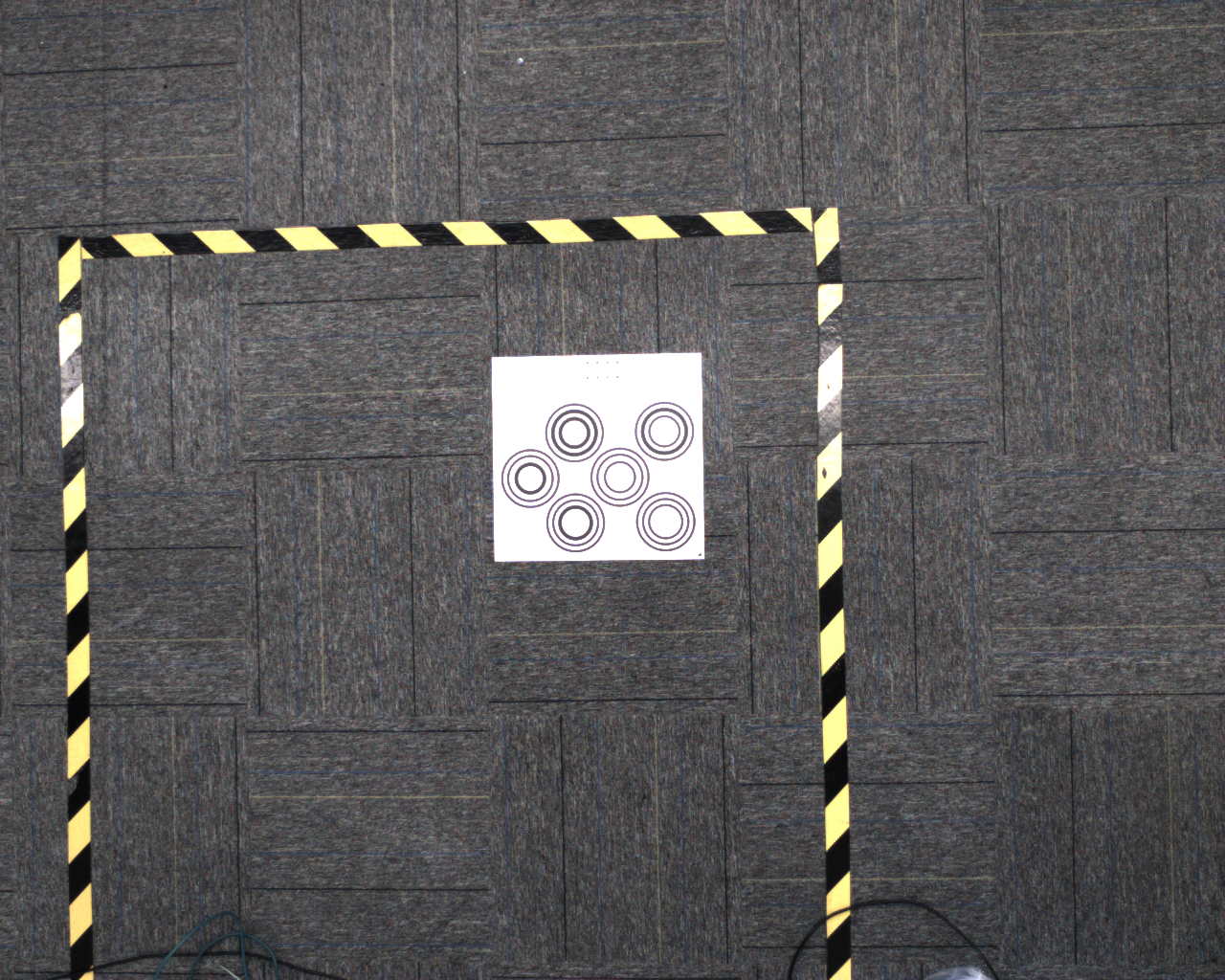 |
|---|---|---|
| Underexposed | Correctly exposed | Overexposed |
2.2 Copy and Edit a Configuration
Default configurations cannot be changed. If a default configuration does not meet the imaging requirements, create an editable configuration as follows:
- On the camera page, select the default configuration you want to copy.
- Click “+” next to the configuration list to create a configuration based on the current one.
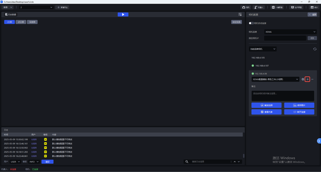
- Select the new configuration in the configuration list.
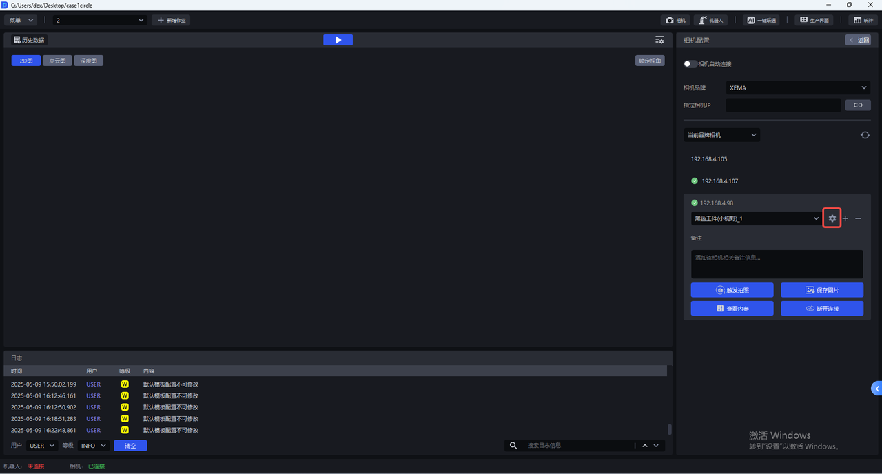
- Click the settings button next to the configuration list to open the camera configuration screen.
- Adjust the parameters based on how the target appears, then trigger another capture to check the results. See Chapter 4 for parameter tuning methods.
- After tuning, select the camera and configuration to use on the “Task Information” page for the current task.
2.3 Save Capture Results
After capturing images, click “Save Images” to save the current 2D image, point cloud, and depth image to the local computer.
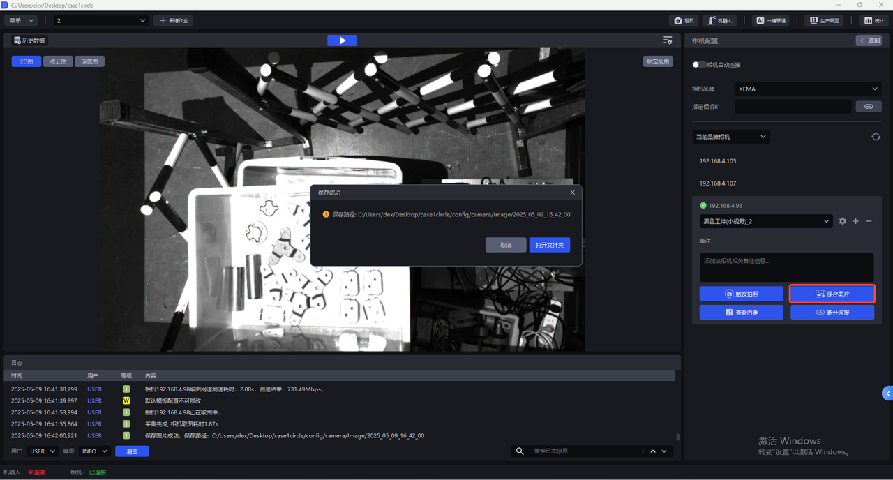
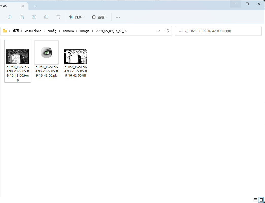
Refer to the actual PickWiz 1.9.0 message for the image save location. Capture results can usually be found under config/camera/image/拍摄时间 in the project folder, where 拍摄时间 is the capture-time folder. .bmp files are 2D images, .ply files are point clouds, and .tiff files are depth images.
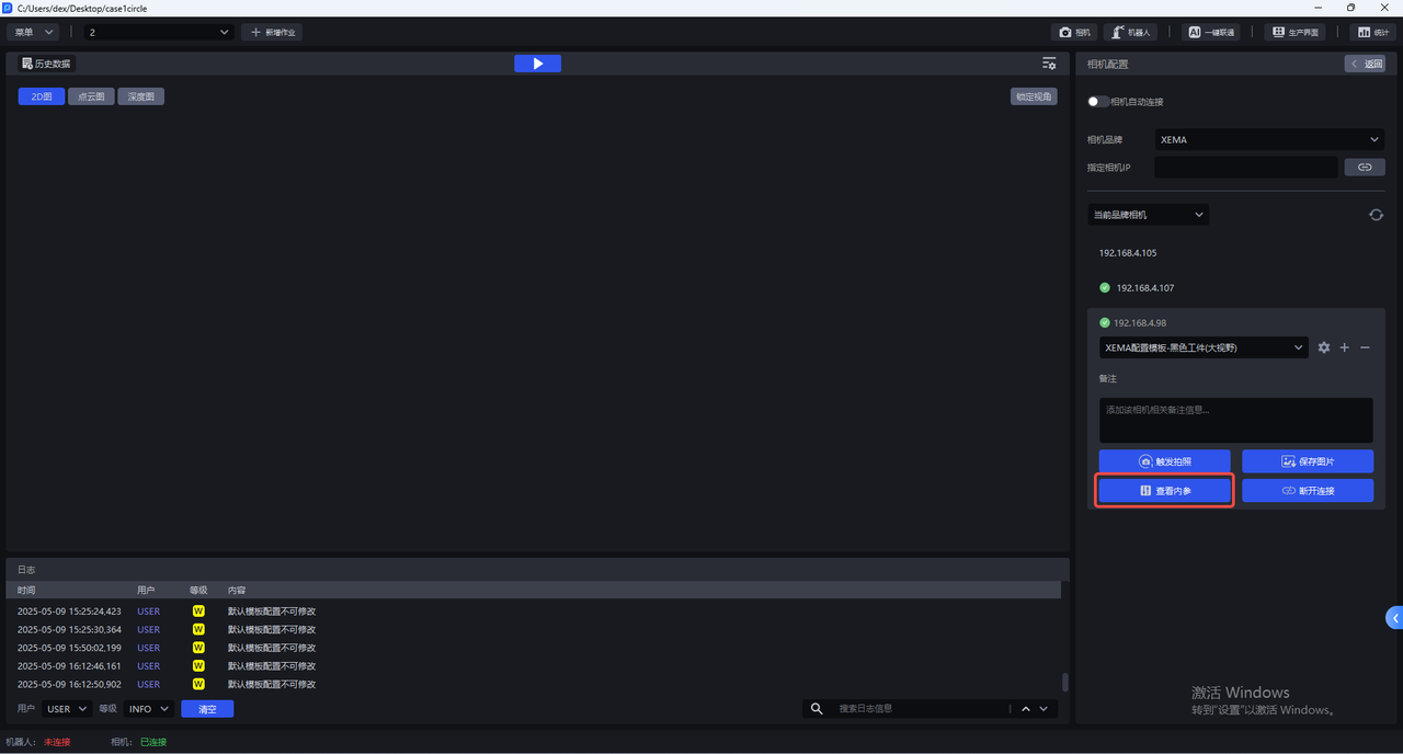
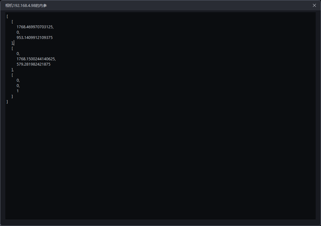
2.4 View Camera Intrinsic Parameters
On the camera page, click “View Intrinsic Parameters” to view the current camera’s intrinsic parameters, including lens focal length, principal point coordinates, and distortion coefficients.
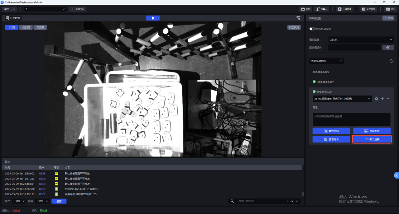
2.5 Disconnect the Camera
To switch devices, click “Disconnect” on the camera page. Disconnect the current camera before selecting the camera you want to connect.
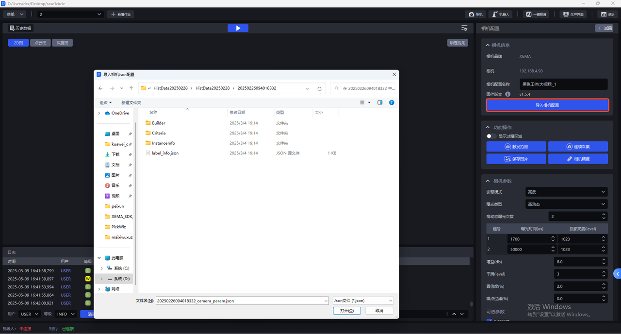
2.6 Import a Camera Configuration
Open the camera configuration screen, click “Import Camera Configuration”, and select an existing configuration file to import. After importing it, check the configuration parameters and trigger a capture to confirm the imaging results.
2.7 Delete a New Configuration
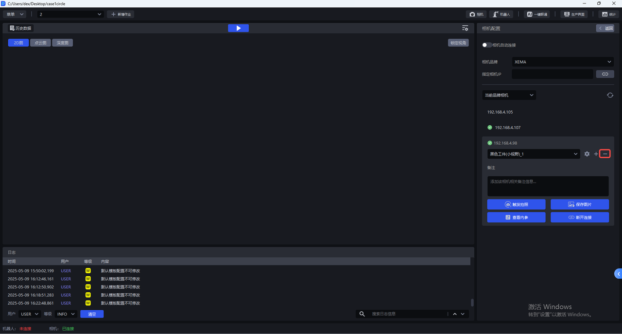
In the configuration list on the camera page, select the new configuration you want to delete and click “—” next to the list. Default configurations cannot be deleted.
2.8 Capture Images and Check Imaging Results
2.8.1 Trigger a Capture
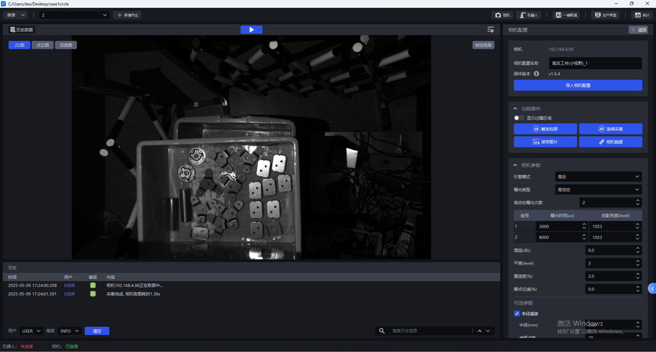
On the camera parameter configuration screen, click “Trigger Capture” to perform one capture using the current configuration. View the resulting 2D image, point cloud, and depth image.
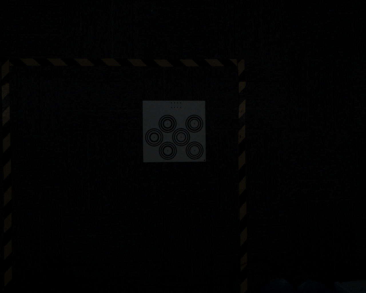
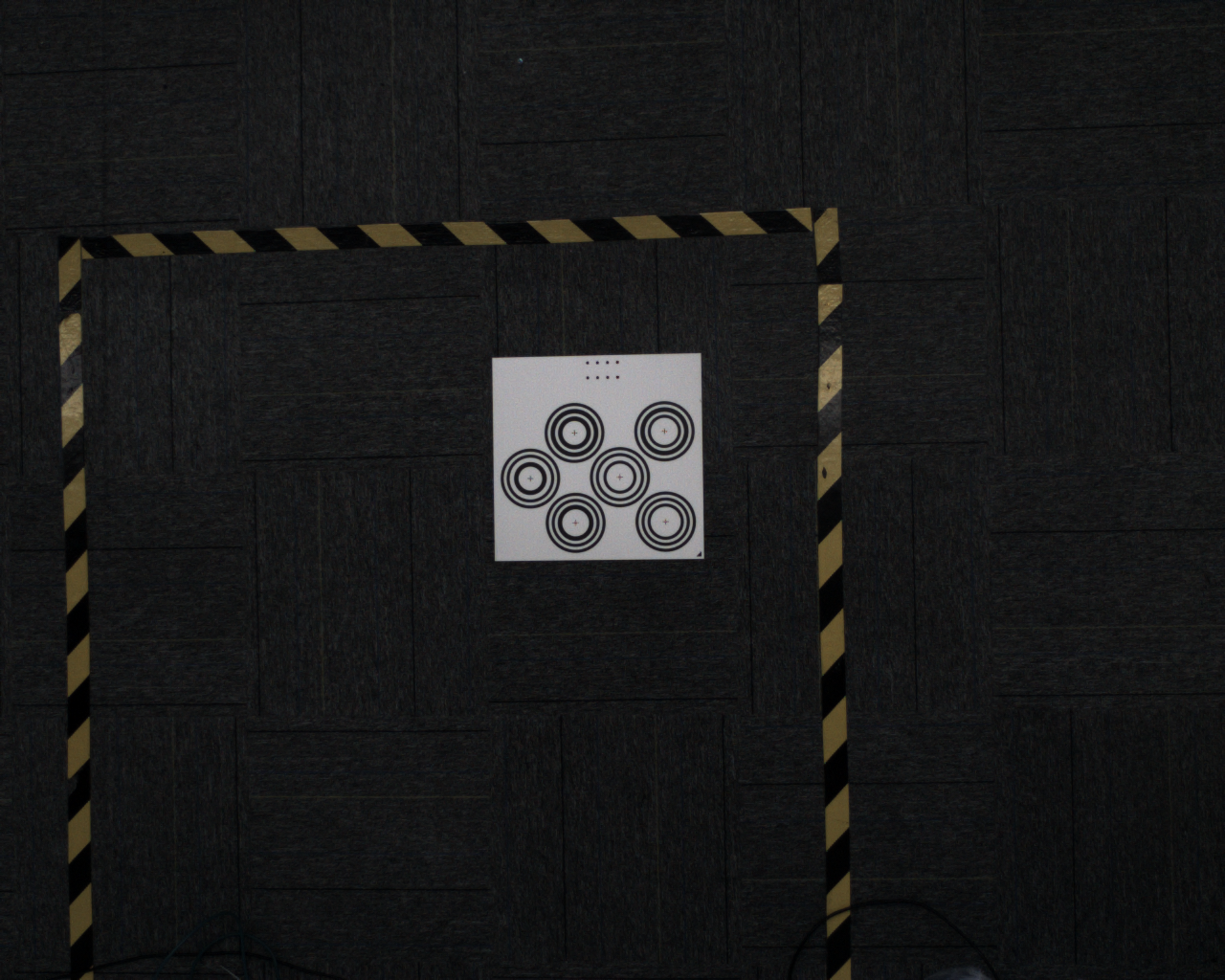
The following exposure examples can help you decide whether the current 2D image needs further adjustment:
 |  | 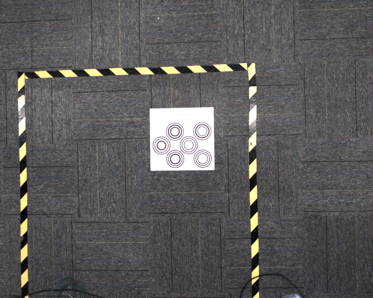 |
|---|---|---|
| Underexposed | Correctly exposed | Overexposed |
2.8.2 Show Overexposed Areas
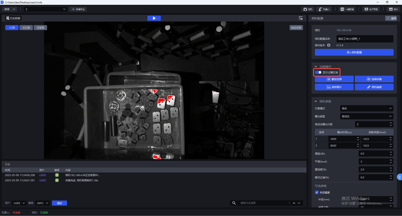
After you enable “Show Overexposed Areas”, the visualization window marks overexposed areas in the current image. This helps you judge whether the exposure time and projection brightness are appropriate.
2.8.3 Continuous Capture
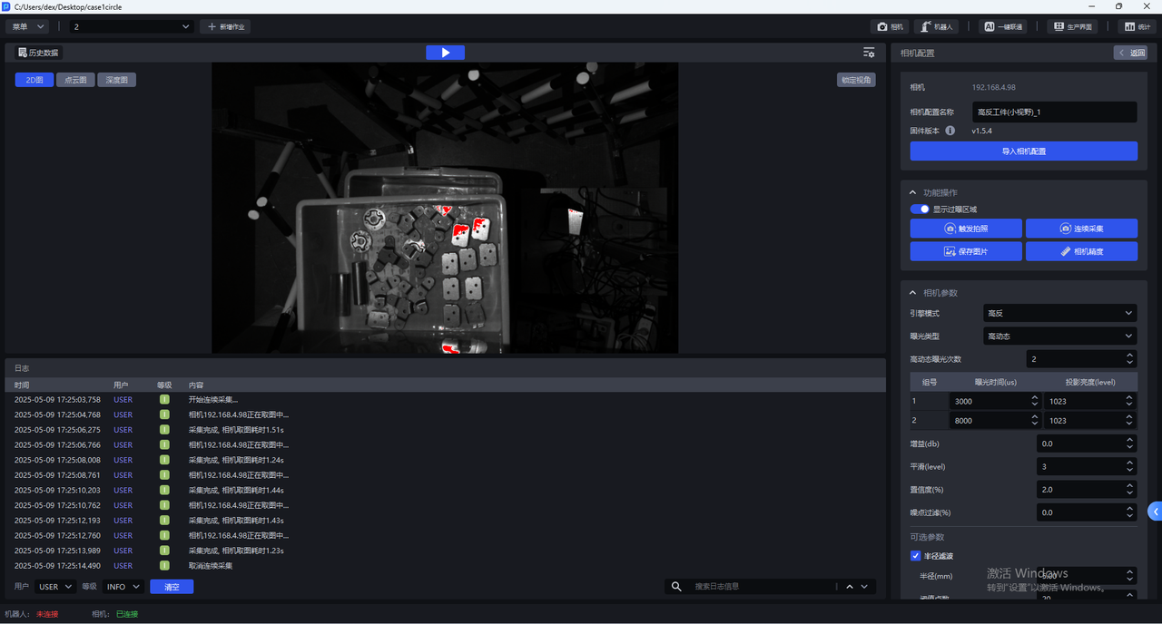
To observe imaging results continuously, click “Continuous Capture”. The camera continues capturing images and updating the visualization window. When you finish observing, click “Cancel Capture” to stop.
3. Camera Accuracy
3.1 View Camera Accuracy
- Place the calibration board within the camera’s field of view and click “Camera Accuracy” on the camera configuration screen.
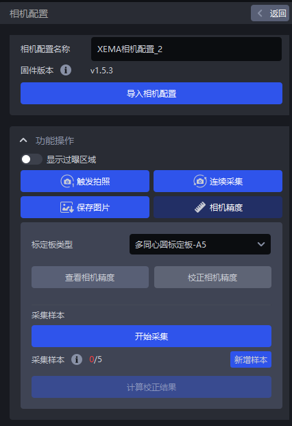
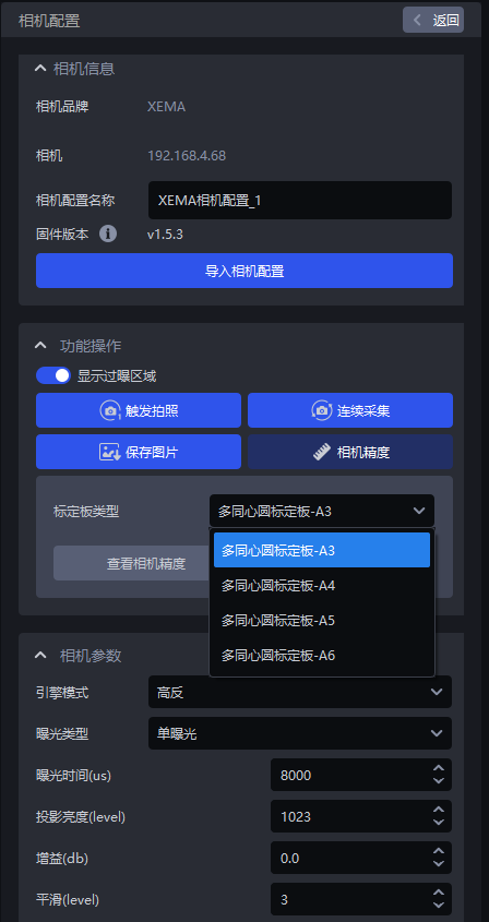
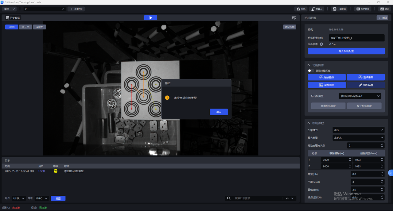
- Select the type that matches the calibration board in use. If the selected type does not match the actual board, the software displays a “Please Check the Calibration Board Type” warning.
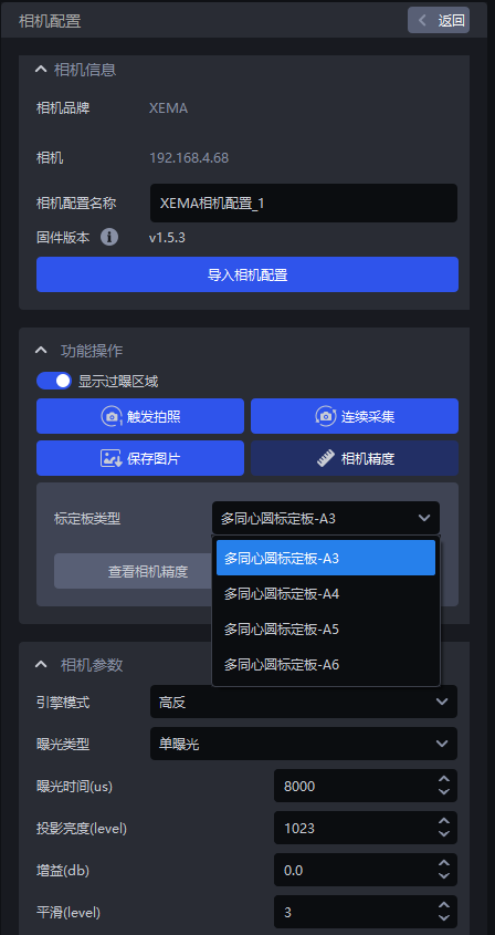
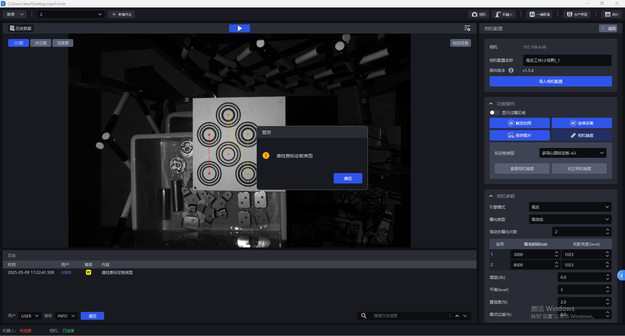
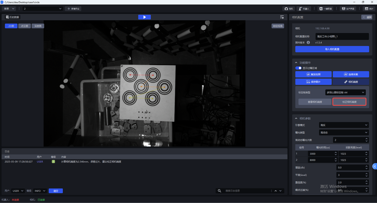
- After selecting the correct calibration board type, click “View Camera Accuracy”. PickWiz automatically calculates the current camera accuracy.
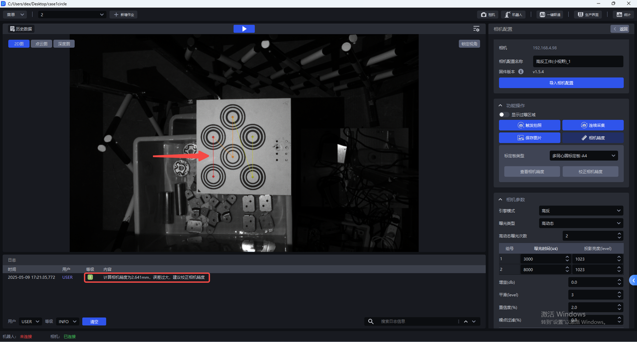
When the camera accuracy of a FINCH series camera is less than 0.8 mm, it can usually be considered to meet the accuracy requirement. The actual acceptance threshold depends on the project requirements. If the software reports that the error is too large, calibrate the camera accuracy before continuing to tune parameters.
3.2 Calibrate Camera Accuracy
During use, and after extrinsic parameter calibration, verify that the current camera accuracy meets the requirements. Recalibration is recommended in the following situations:
- The error is abnormal when viewing camera accuracy.
- The point cloud captured by the current camera shows substantial surface fluctuations.
- The camera mounting position, lens, or related hardware has been changed.
Checks Before Calibration
Before calibration, enable “Show Overexposed Areas” and check that single exposure imaging is normal. If any area is overexposed, adjust the single exposure time first to avoid collecting calibration samples from overexposed images. After calibration, switch the camera imaging parameters back to the original configuration.
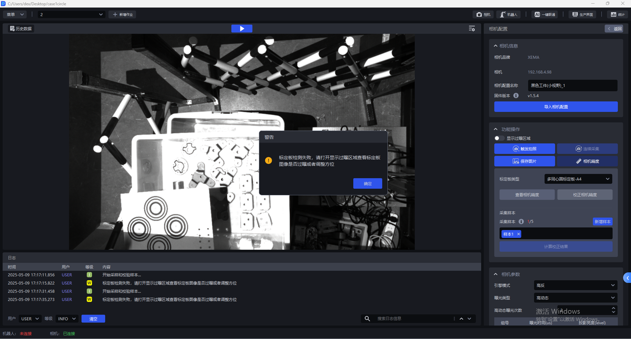
- Click “Camera Accuracy” on the camera configuration screen.
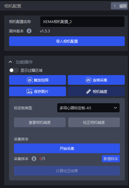
- Select the type that matches the calibration board in use.
- After selecting the correct calibration board type, click “Calibrate Camera Accuracy”.
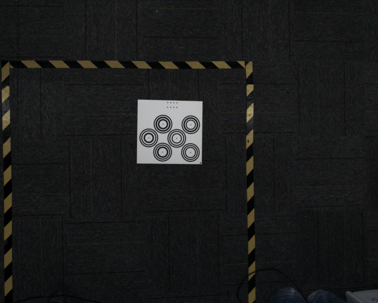
- Place the calibration board horizontally in the center of the camera’s field of view and click “Add Sample”. The camera starts collecting and validating a sample. Samples that pass validation are added to the “Collected Samples” list.
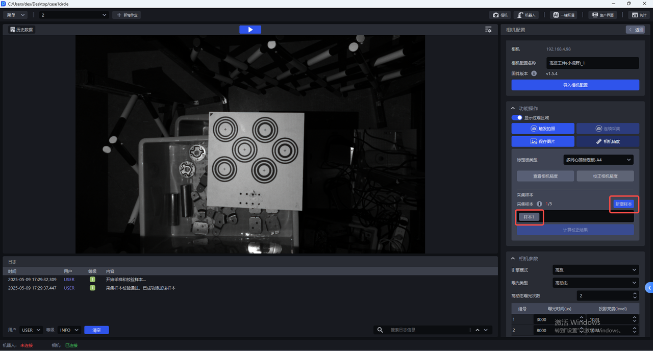
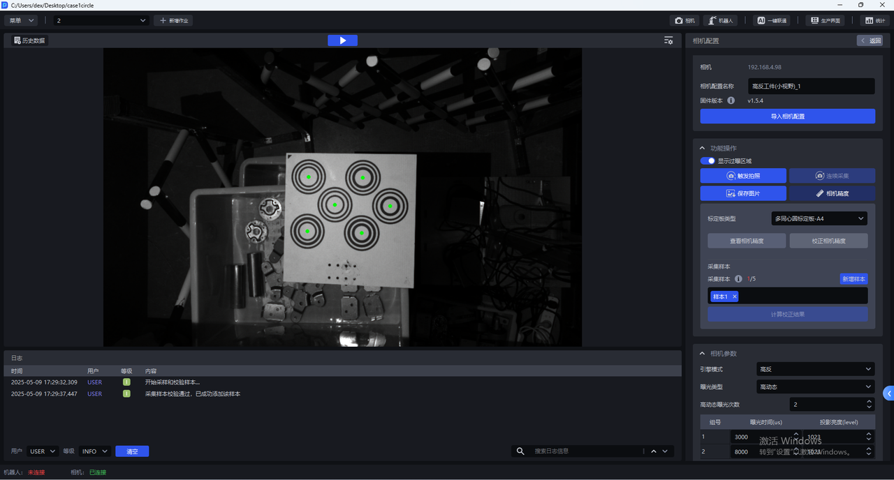
Click “Sample x” to view a collected sample. When validation passes, the centers of all concentric circles on the calibration board are shown in green.
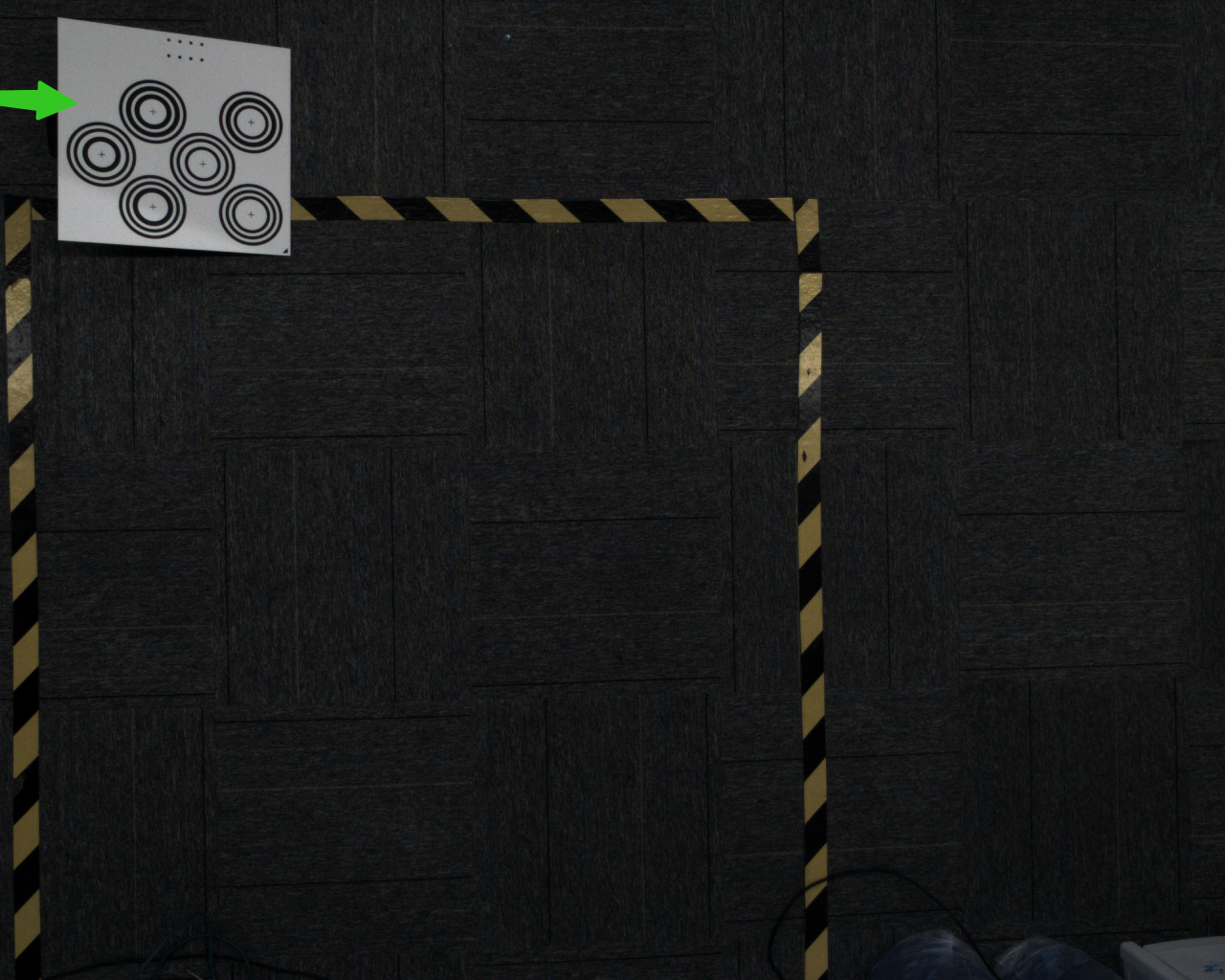
- Move the calibration board to each of the four corners within the camera’s field of view, adding a sample at each corner. At each corner, you can prop up the calibration board at an angle. The recommended placement angle is 15°~30°; the tilt angle must be neither too large nor too small.
 | 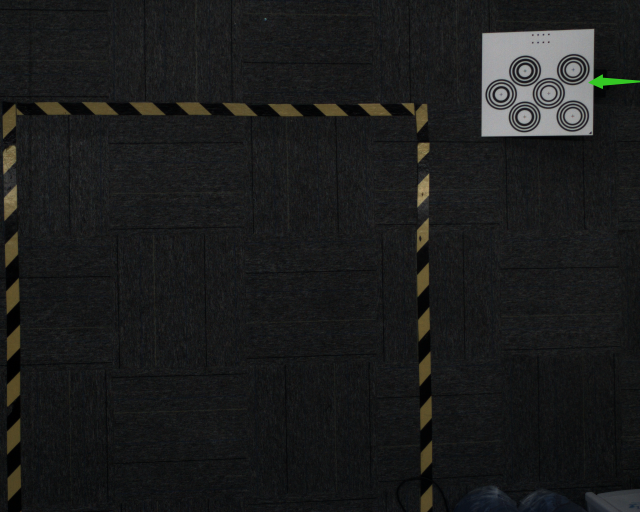 | 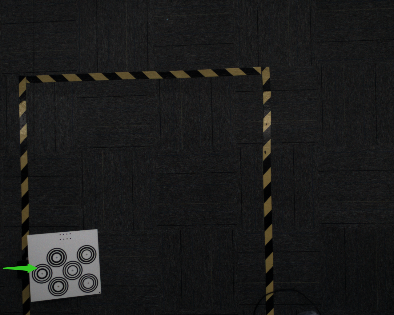 | 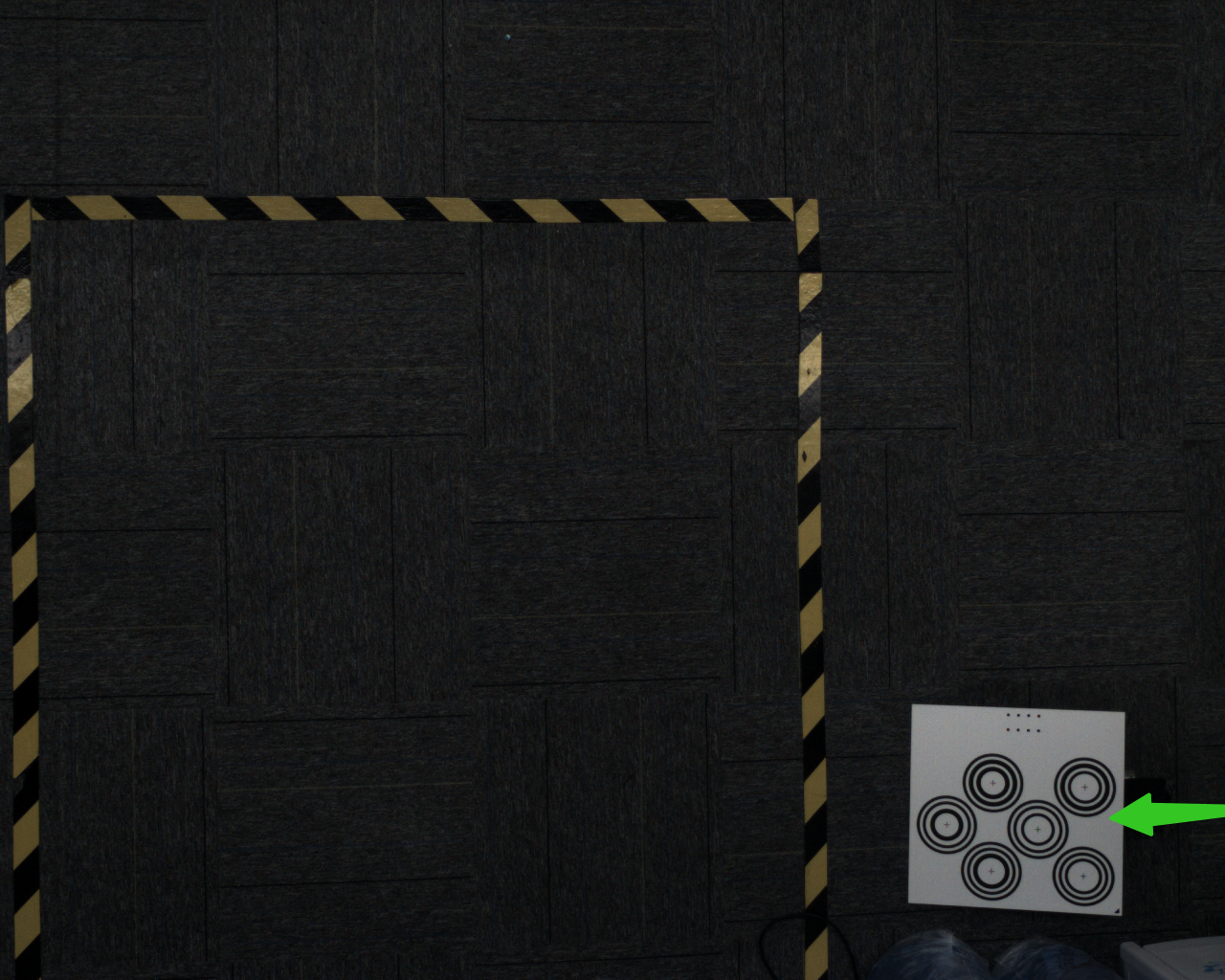 |
|---|
- After adding the center sample and four corner samples, for a total of 5 samples, click “Calculate Calibration Result”.
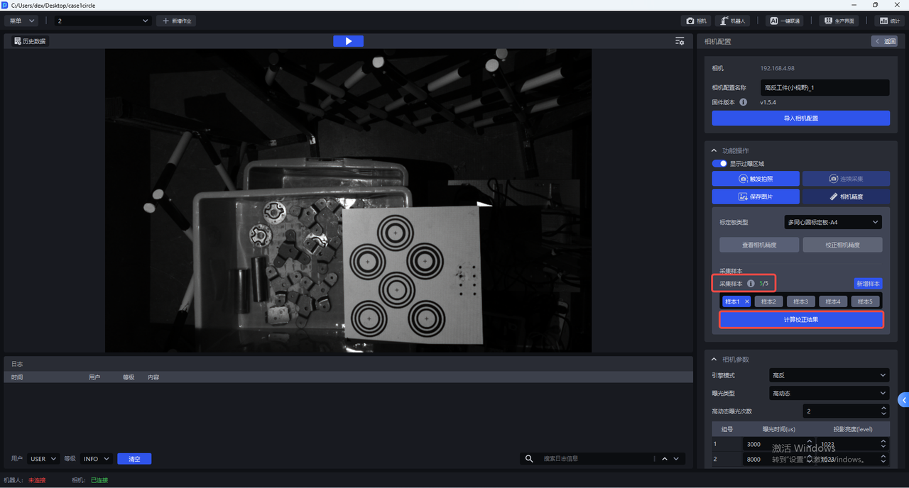
- After calibration, the software displays “Camera accuracy calibration complete. The calibrated accuracy is x, the error is normal. Overwrite the current camera parameter configuration?”
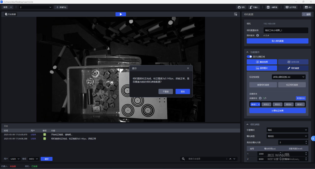
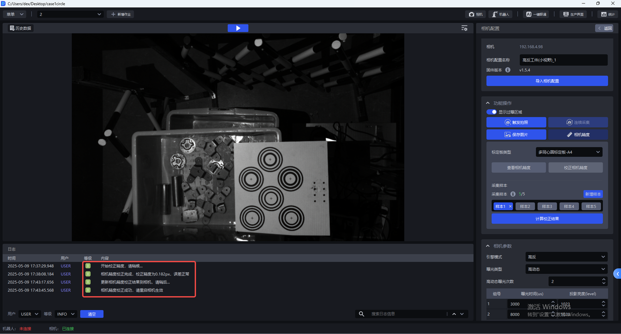
If you choose to overwrite the current camera parameter configuration, the calibration result is written to the camera. The camera usually needs to be restarted for the result to take effect.
4. Camera Parameter Tuning
This chapter recommends tuning parameters in the following order: imaging first, then the point cloud, and finally the overlay output. Adjust only one parameter at a time. After triggering a capture, check the 2D image, point cloud, and depth image together. Continue to the next parameter only after confirming a stable improvement.