
FINCH Series Camera Hardware Installation Manual
Welcome to DexForce products!
This manual guides you from unpacking and inspection through hardware installation. Illustrations are for reference only; the actual product shall prevail.
1. Unpacking inspection
After receiving the package, confirm that it is intact and undamaged. Check the product and accessories against the packing list, and promptly confirm that no items are missing or damaged.
1.1 Accessories
Important
The following list is for reference only. Accessories may vary by camera model. Refer to the packing list included with the actual product.
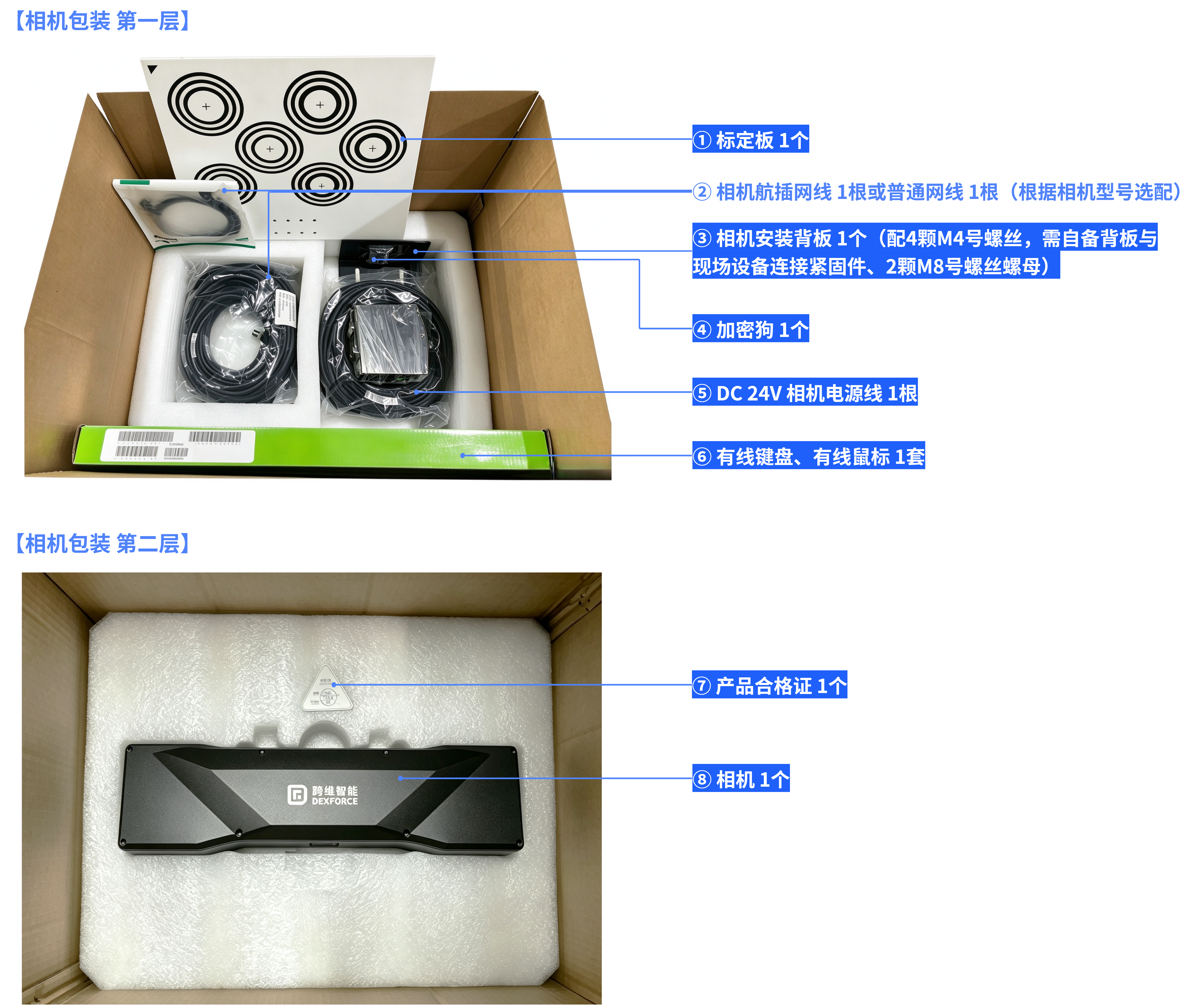
| No. | Item | Quantity | Notes |
|---|---|---|---|
| 1 | Calibration board | 1 | - |
| 2 | Circular-connector or standard camera Ethernet cable | 1 | Selected according to the camera model |
| 3 | Camera mounting backplate | 1 | Includes four M4 screws; provide the fasteners for the on-site equipment and two M8 bolts and nuts |
| 4 | USB dongle | 1 | - |
| 5 | DC 24 V camera power cable | 1 | - |
| 6 | Wired keyboard and mouse | 1 set | - |
| 7 | Product certificate | 1 | - |
| 8 | Camera | 1 | - |
| 9 | Industrial PC | 1 | Includes a power cable, mounting screws, product certificate, network antennas, and other accessories |
| 10 | Monitor | 1 | Includes a power cable and HDMI cable |
2. Hardware installation preparation
2.1 Tools and equipment to provide
| M4 hex key | M8 bolts, nuts, and matching tools | Ladder and safety equipment |
|---|---|---|
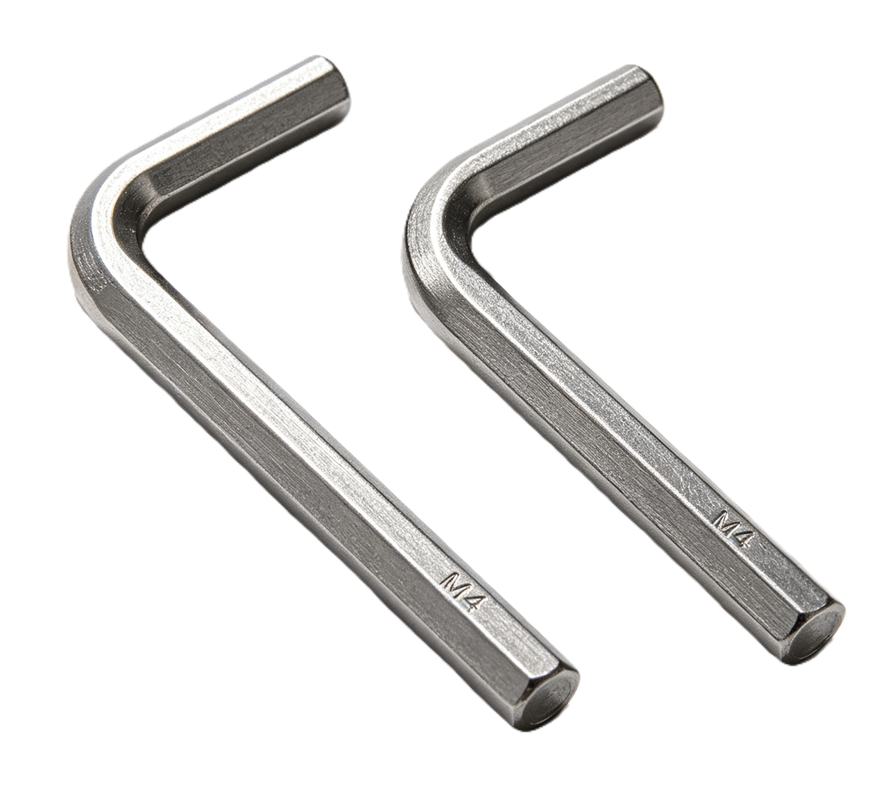 |  |  |
| 1 | 2 | Prepare as required at the site |
2.2 Precautions
Make sure the camera operating environment meets the following conditions:
- Power is available and a Gigabit Ethernet network is provided.
- Temperature, humidity, impact, and other environmental conditions comply with the camera specifications.
- Ventilation and heat dissipation are adequate. Do not use the camera in a completely enclosed space, such as a sealed protective enclosure.
- The distance from the camera to the target surface is within the recommended working-distance range.
- Plan the robot path and take other appropriate measures to prevent collisions between the camera and surrounding equipment.
3. Hardware overview
| Device | Ports and indicators |
|---|---|
FINCH-W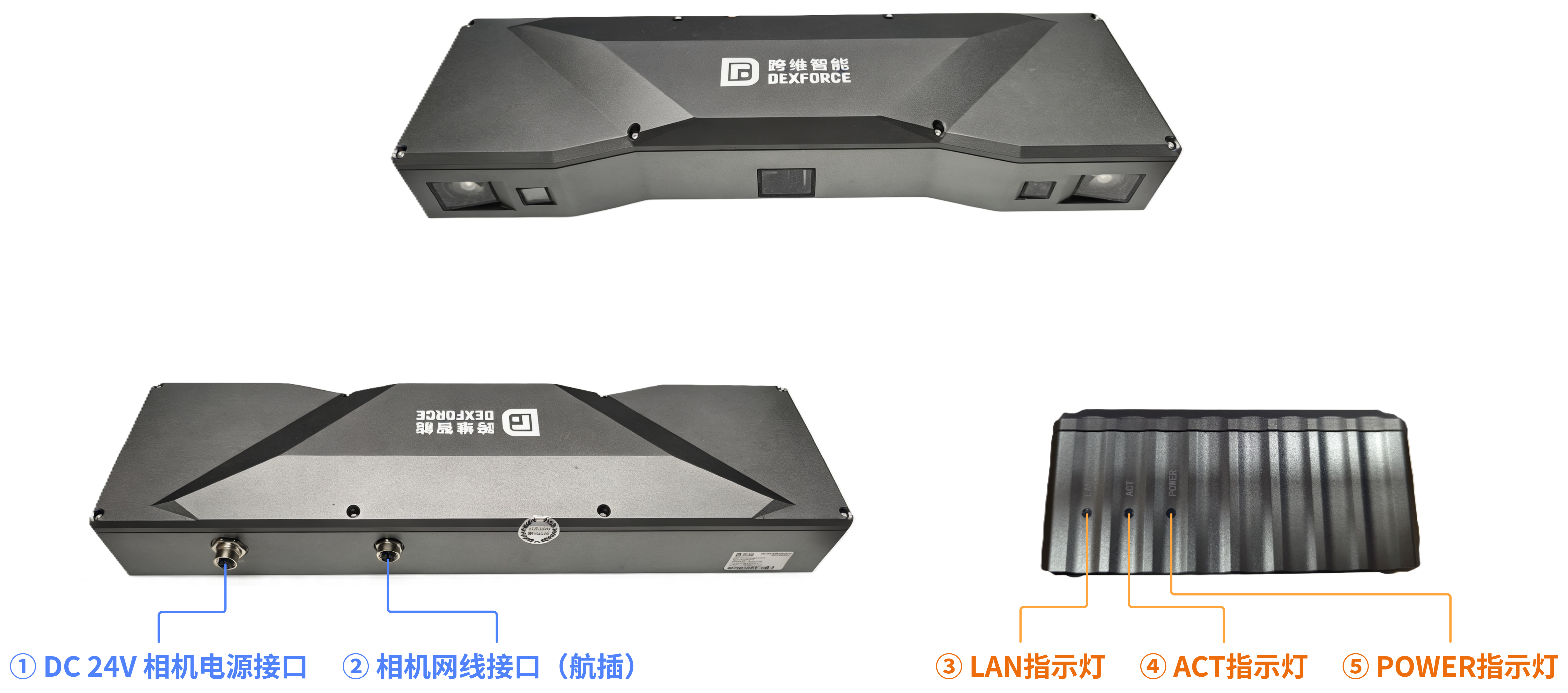 | ① DC 24 V camera power port: Connect the DC 24 V camera power cable. ② Camera Ethernet port (circular connector): Connect to the industrial PC using a circular-connector Ethernet cable. ③ LAN indicator:
|
Industrial PC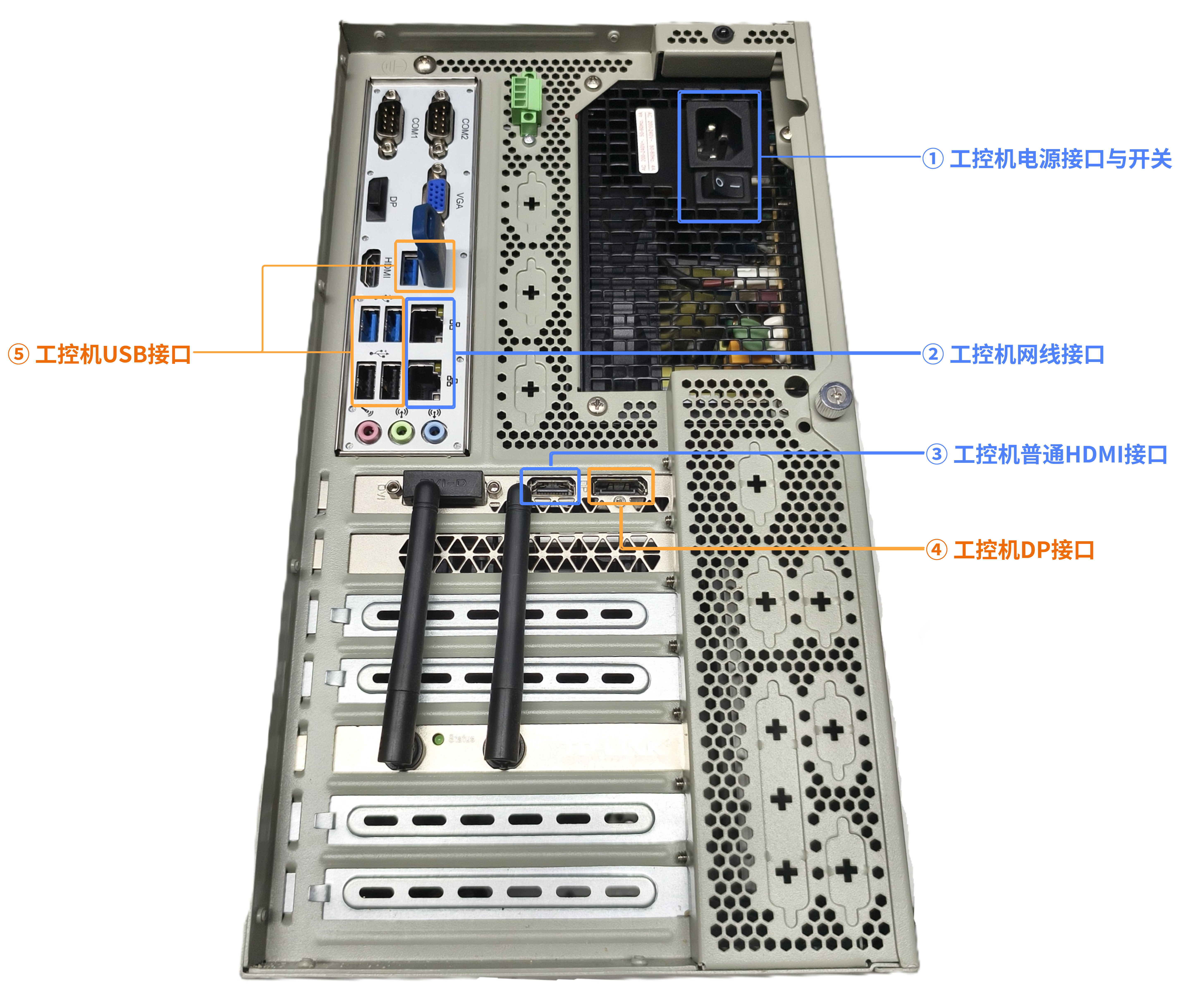 | ① Power connector and switch: Connect the industrial PC power cable and control its power. ② Ethernet ports: Use a standard Ethernet cable for the local Gigabit Ethernet network and a circular-connector Ethernet cable for the camera. ③ HDMI port: Standard HDMI port. ④ DP port: Connect the monitor using its supplied HDMI cable (recommended). ⑤ USB ports: Connect the USB dongle, mouse, keyboard, and other peripherals. |
4. Hardware installation
| Robot-end mounting | Fixed-bracket mounting |
|---|---|
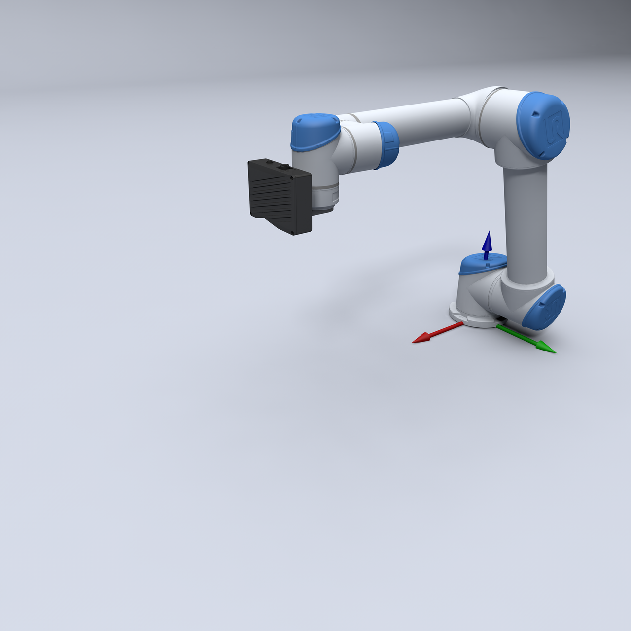 | 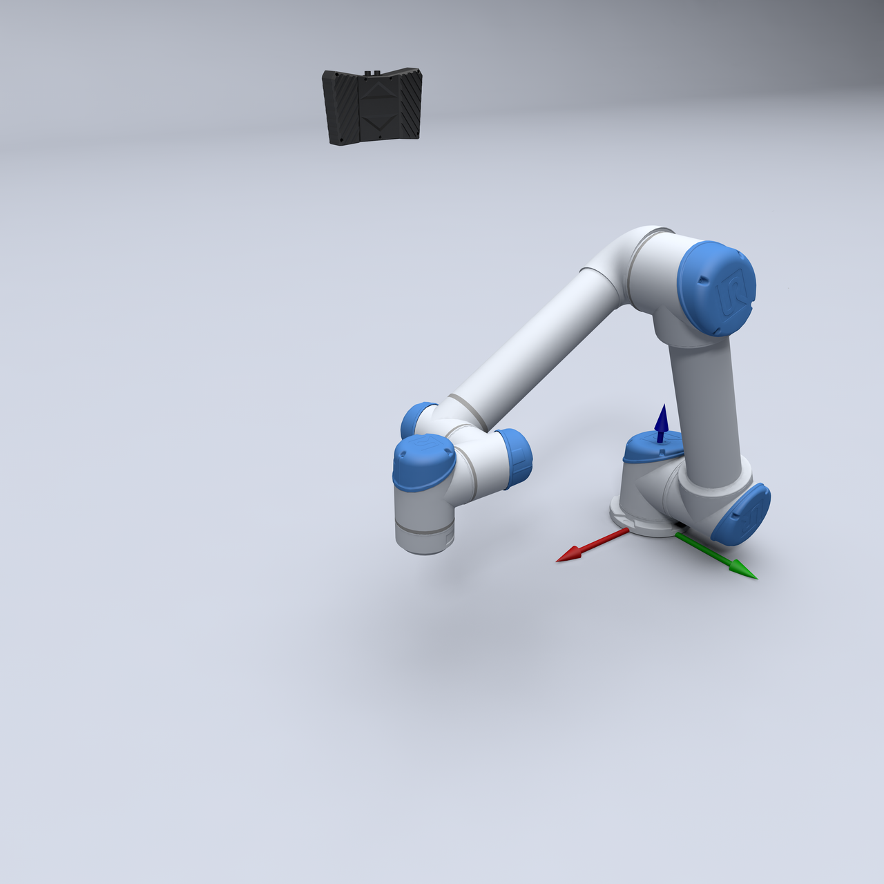 |
| The camera moves with the robot. | The camera remains fixed on the bracket. |
Warning
- When the camera is mounted on a robot arm or another moving device, securely fasten the power and Ethernet cables to prevent pulling forces from damaging the cables or connectors.
- When the camera is mounted on a bracket, make sure the long edge of the camera field of view is parallel to the long edge of the pallet or bin. This keeps the top layer of the stack within the effective field of view.
4.1 Attach the camera mounting backplate
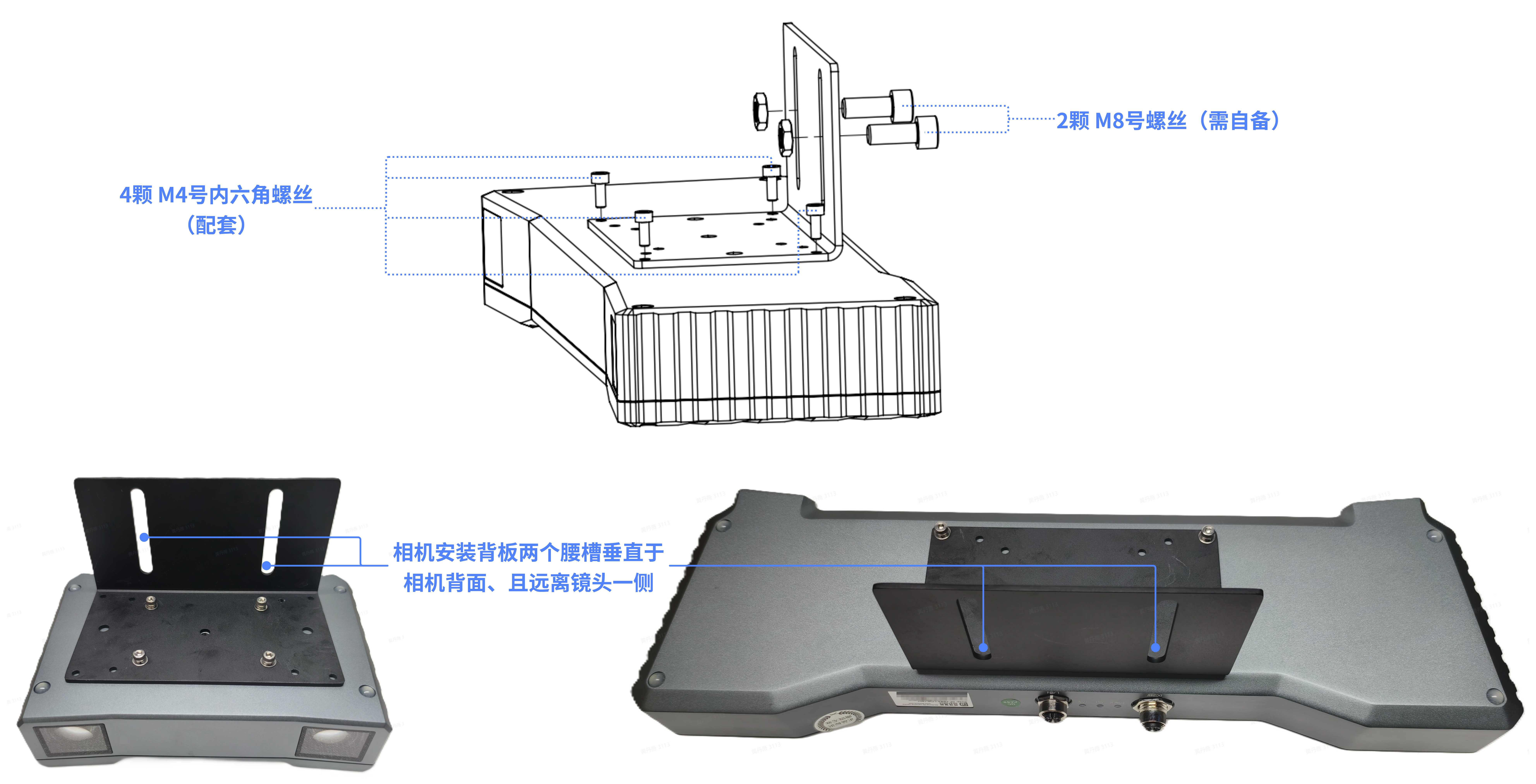
Use four M4 hex-socket screws to attach the mounting backplate to the rear of the camera. The two elongated slots in the backplate must be perpendicular to the rear surface of the camera. Then use two M8 bolts (not supplied) to mount the camera and backplate assembly on the robot end flange or camera mounting bracket.
4.2 Connect the camera
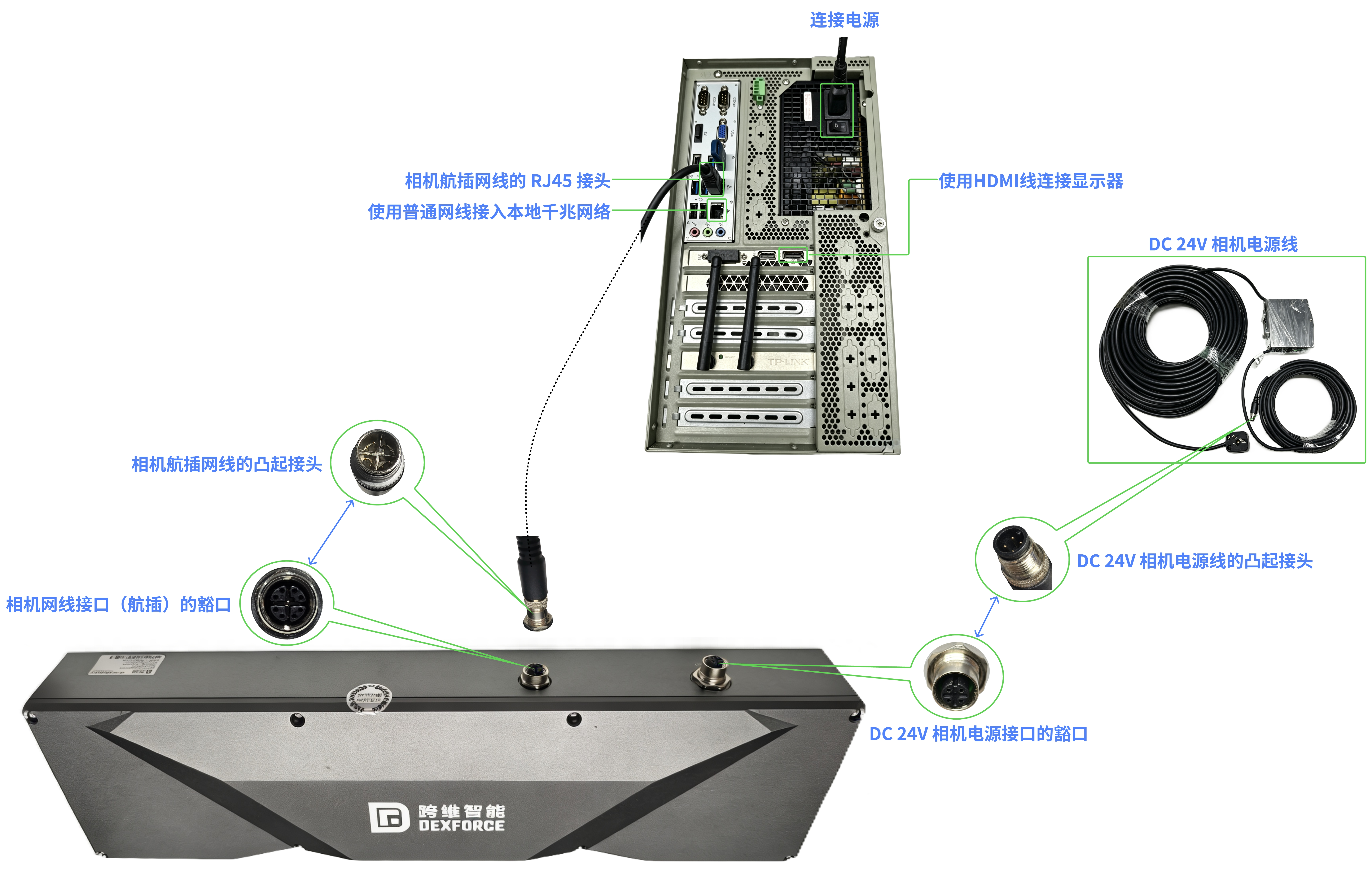
Connect a DC 24 V power cable to the camera power port. At the same time, connect the camera Ethernet port to the industrial PC with a circular-connector Ethernet cable. Insert the keyed circular connector into the camera port and the RJ45 connector into the industrial PC.
Warning
Tighten the camera Ethernet connector screws. A loose connector may accelerate port wear or cause poor contact.
4.3 Check the connections
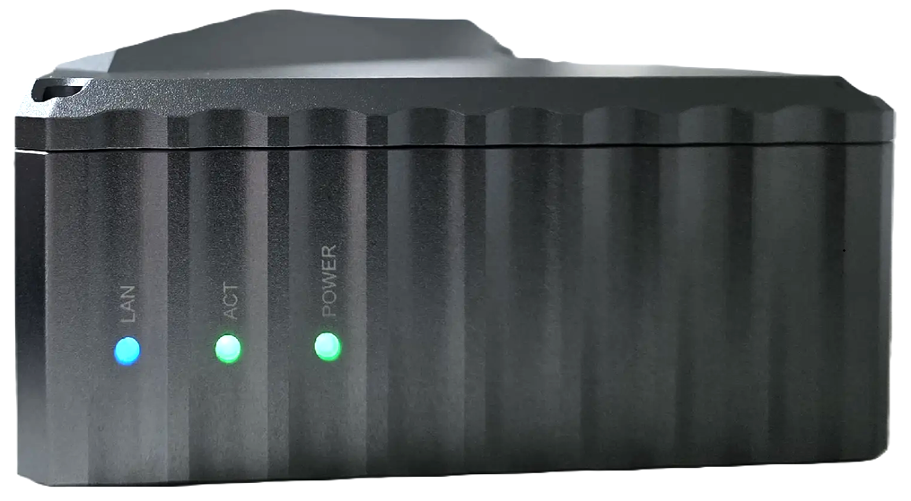
Verify that all devices are connected correctly and all cables are securely fastened without being pulled or strained. Then turn on the power. The LAN indicator should alternate blue and green, and the ACT and POWER indicators should be steady green.
4.4 Installation complete
The camera hardware installation and connection are complete.