
KINGFISHER Camera Parameter Tuning Guide
This guide covers connecting, configuring, correcting the accuracy of, and tuning the imaging parameters of KINGFISHER series stereo cameras in PickWiz 1.9.0.
Before starting, install the camera and connect it to power and the network. For hardware installation, see the KINGFISHER Series Camera Hardware Installation Manual. To return to the series overview, see the Camera Connection and Tuning Guide.
KINGFISHER is a stereo camera composed of left and right 2D cameras. PickWiz uses the left and right images and a stereo model to generate a point cloud. When tuning the camera, check the left and right images, point cloud, and depth image together.
1. Connect the Camera
In PickWiz 1.9.0, the KINGFISHER connection workflow is enumerate → pair → connect. The software automatically enumerates left and right cameras on the network. After pairing, it uses the left camera's device ID as the primary ID of the stereo system.
1.1 Preconnection Checks
Confirm the following before opening PickWiz:
- The cameras have been installed according to the hardware installation manual and are powered through a PoE switch.
- The industrial computer, PoE switch, and cameras are on the same network.
- The KINGFISHER cameras are not occupied by MVS or another camera system.
- You have recorded the serial numbers of the left and right cameras so you can match the factory intrinsic and extrinsic calibration file.
1.2 Enumerate and Pair the Cameras
- Open the “Camera” page in PickWiz 1.9.0.
- Select “KINGFISHER” under “Camera Brand” to enter the stereo enumeration and pairing workflow.
- Select the device list scope from the “Current Brand Cameras” dropdown, then click “Refresh” to enumerate KINGFISHER devices on the network again.
- Select the left and right devices from the “Select Left/Right Camera” dropdowns. You may select only the left camera; the software will automatically match its right camera.
- Click “Connect”. Using the selected left camera's ID as the stereo system's primary ID, the software connects the left and right cameras in sequence and establishes the stereo system.
Caution
Close MVS before connecting so that it does not occupy the devices. If either camera fails to connect, pairing fails and the connected device is disconnected. Neither selected device can be in use by another camera system.
When “Camera Auto Connect” is on, the software attempts to reconnect using the saved camera configuration. Turning it off stops automatic reconnection. Consider turning it off temporarily during initial setup, network troubleshooting, or camera replacement.
1.3 Confirm the Connection Status
After connection and pairing, check the status in the device list:
- A green status icon before a device ID means the device is available or connected.
- If the status does not show “Connected”, check the camera power supplies, network cables, industrial computer network adapter, IP addresses, whether MVS is closed, and whether MVS can detect both cameras.
1.4 Import the Intrinsic and Extrinsic Calibration File
The KINGFISHER intrinsic and extrinsic calibration file describes the relative positions of the left and right cameras. After connecting, import the matching factory calibration file based on their serial numbers.
- Specify the stereo calibration YAML under “Intrinsic and Extrinsic Configuration” on the main screen. The software may attempt to read it from the camera memory and generate a
*_from_memory.yamlfile. - For a manual import, confirm that the calibration file matches the current left and right devices and their resolution.
- Save the configuration and trigger a capture to confirm that the left and right images and point cloud can be generated.
1.5 Check the Connection and Stereo Rectification
After connecting and importing the calibration file, click “Trigger Capture” and check the following:
- Both left and right 2D images appear normally, with no obvious difference in brightness or color.
- A point cloud and depth image are generated, with no large missing area on the target.
- After saving the capture results, the red lines in the left and right images of
rect.bmppass through the same point in the scene.
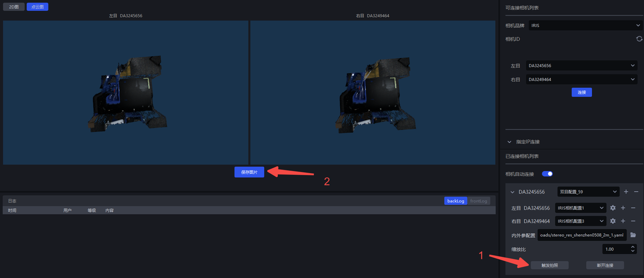
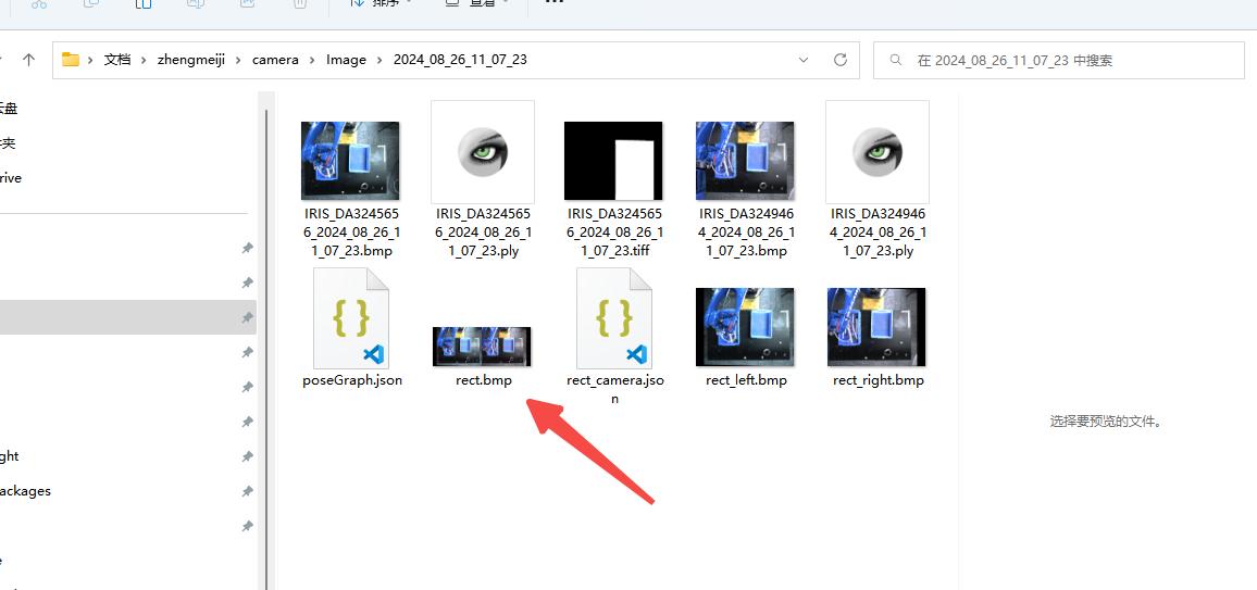
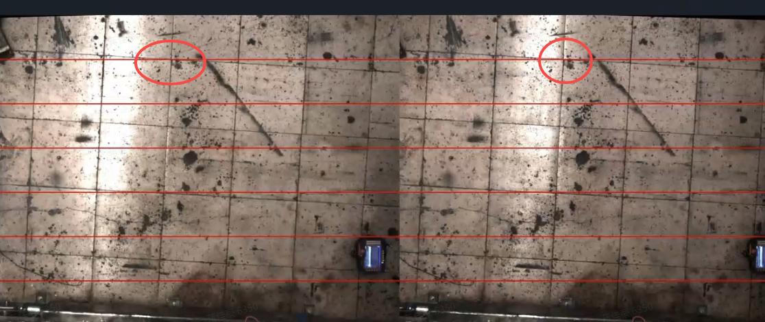
If the red lines do not pass through the same scene point, first recheck the calibration file and the left and right serial numbers. If the issue persists, correct camera accuracy as described in Chapter 3 and consult technical staff about whether a new extrinsic calibration file is needed.
2. Camera Configuration
A camera configuration stores a set of capture and imaging parameters. After connecting, you can select a default configuration to check the imaging results. To adjust parameters, copy the default configuration and edit the new one.
A complete KINGFISHER configuration contains the left and right devices, their parameter templates, the calibration YAML, imaging model, scale factor, camera-to-nearest-target distance, and shadow mode settings. Switching configurations applies all of these together.
2.1 Select a Camera Configuration
Find the connected KINGFISHER camera on the “Camera” page, expand the “Stereo System Configuration” dropdown, and select a default configuration suitable for the current target.
Default configurations cannot be modified. To adjust their parameters, copy the configuration first as described in Section 2.2.
Click “Trigger Capture” to capture a 2D image, point cloud, and depth image with the selected configuration. Check the results in the visualization window.
Use the following examples to judge whether the 2D image exposure is appropriate:
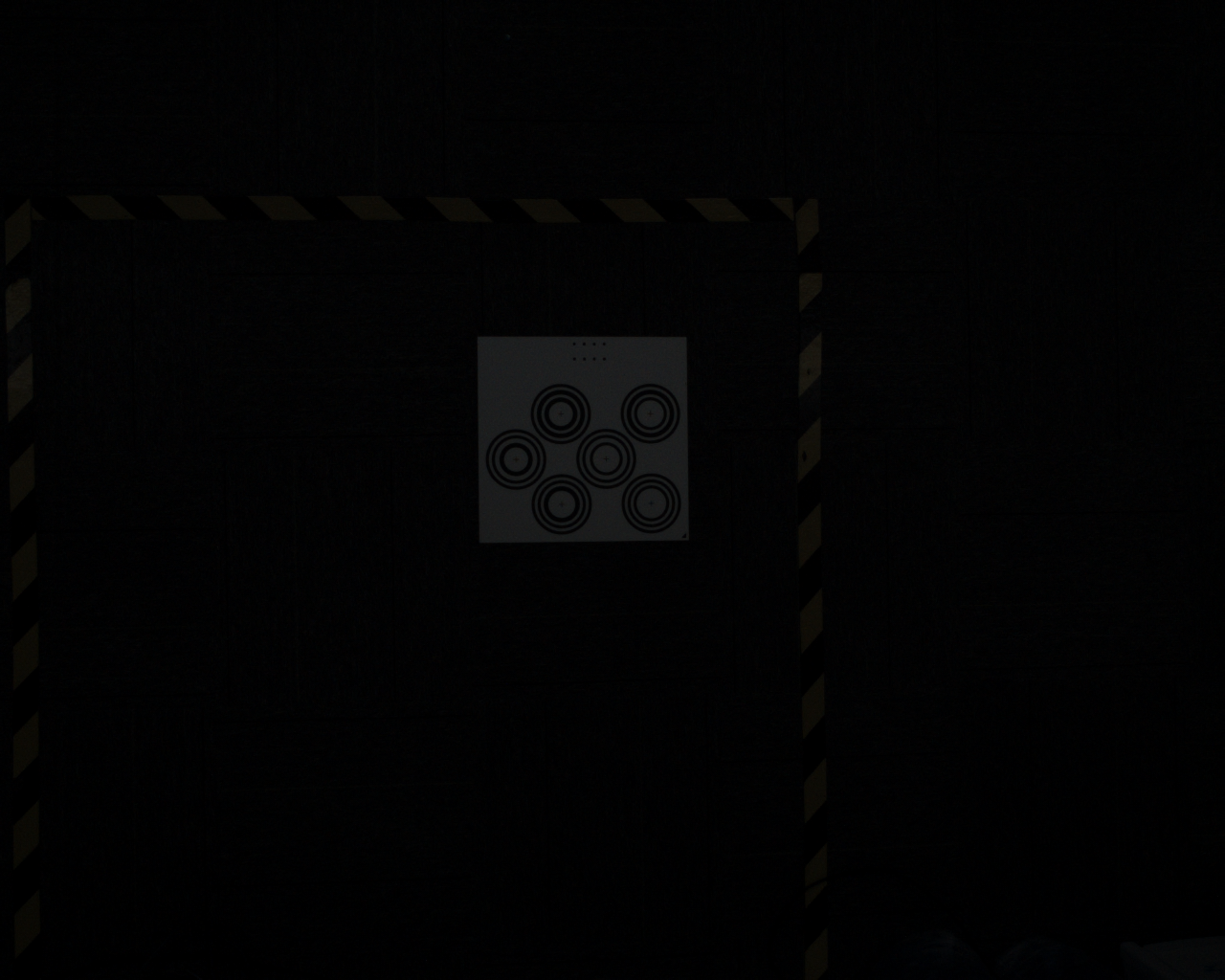 | 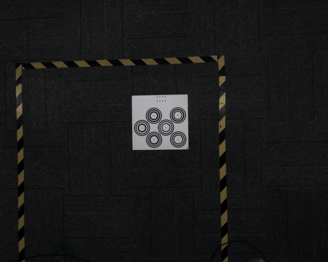 | 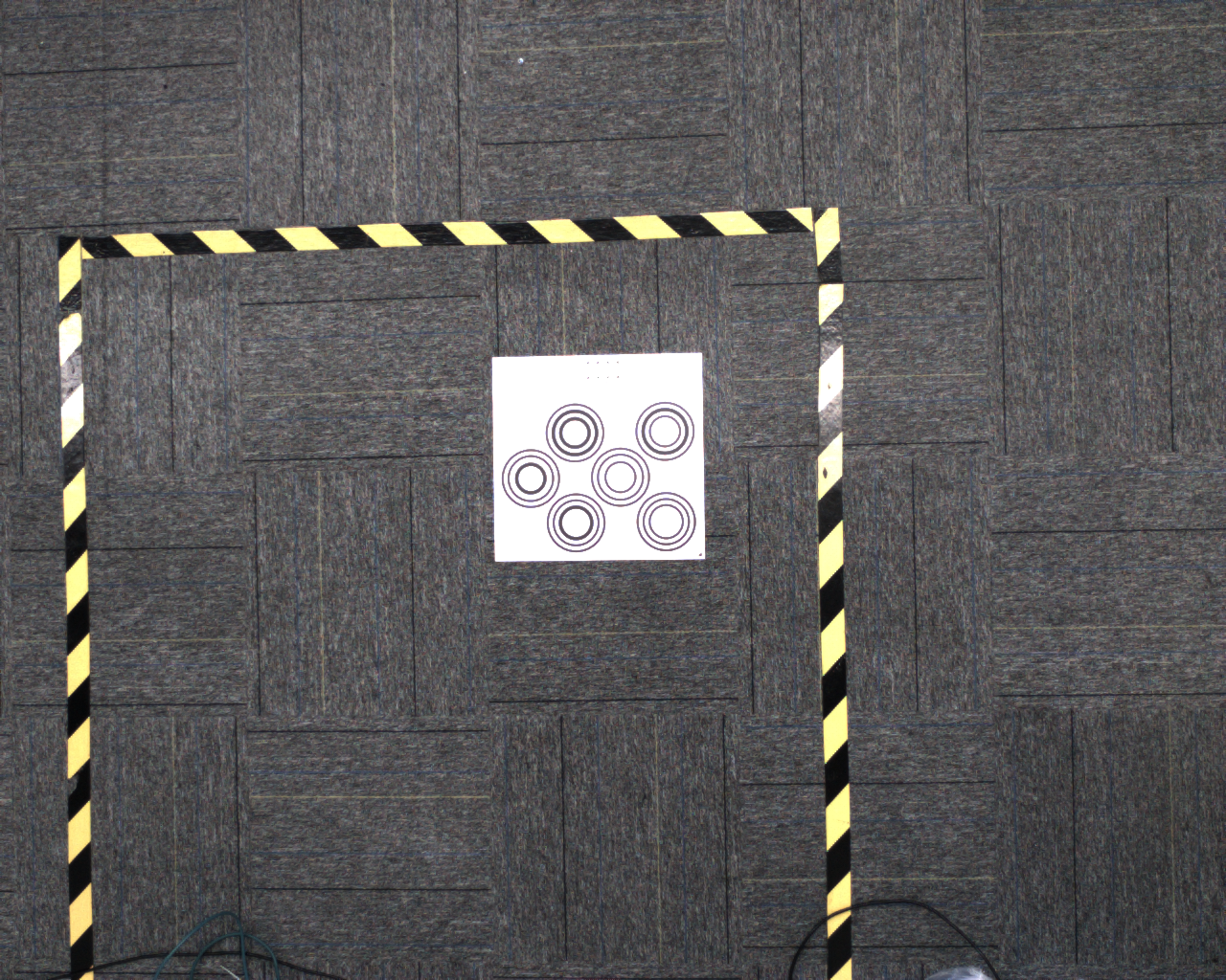 |
|---|---|---|
| Underexposed | Correctly exposed | Overexposed |
2.2 Copy and Edit a Configuration
Default configurations cannot be changed. If one does not meet the imaging requirements, create an editable configuration:
- Select the default configuration to copy on the camera page.
- Click “+” beside the configuration list to create a configuration based on the current one.
- Select the new configuration in the list.
- Click the settings button beside the list to open the camera configuration screen.
- Adjust parameters based on the target image, then trigger another capture to check the result. See Chapter 4 for tuning procedures.
- When tuning is complete, select the camera and configuration for the current task on the “Task Information” page.
2.3 Left and Right Parameter Templates
The left and right cameras can each use a separate parameter template:
- The gear button opens template editing.
- “+” creates a template; “−” deletes one.
- Both cameras can share one template to keep their images consistent, or you can fine-tune them separately to account for actual brightness differences.
Before tuning, confirm whether you are editing the left or right camera, its device ID, and the template name so you do not change the wrong camera.
2.4 Imaging Model and Scale Factor
“Imaging Model” selects the model used to generate stereo depth and point clouds. The edit button changes model information, while the import button adds a model. A default model usually cannot be deleted or have its path changed.
“Scale Factor” is the point cloud scale coefficient. Its range is 0.01–1.00 in steps of 0.01; keep it at 1.00 under normal conditions. Adjust it only after confirming a systematic scale error and verifying the calibration.
2.5 Camera-to-Nearest-Target Distance
This parameter is measured in mm, ranges from 200 to 5000, and defaults to 2000. Enter the actual distance from the camera to the nearest target, or a slightly smaller value. A value greater than the actual nearest distance may clip valid point cloud data.
2.6 Save Capture Results
After a capture, click “Save Image” to save the current 2D images, point cloud, and depth image locally.
Use the location shown by PickWiz 1.9.0 as the authoritative save path. Capture results can usually be found under config/camera/image/拍摄时间 in the project folder: .bmp files are 2D images, .ply files are point clouds, and .tiff files are depth images.
2.7 View Camera Intrinsic Parameters
On the camera page, click “View Intrinsic Parameters” to inspect the current camera's focal length, principal point coordinates, distortion coefficients, and other intrinsic parameters.
2.8 Disconnect the Camera
To switch devices, click “Disconnect” on the camera page. After disconnecting the current camera, select the camera to connect. See Chapter 1 for the connection procedure.
2.9 Import a Camera Configuration
To use an existing configuration file, open the parameter configuration screen of an editable configuration, click “Import Camera Configuration”, and select the file. After importing it, review the parameters and trigger a capture to confirm the imaging result.
2.10 Delete a New Configuration
Select the new configuration to delete from the list on the camera page and click “−” beside the list. Default configurations cannot be deleted.
2.11 Capture and Check Imaging
2.11.1 Trigger Capture
Click “Trigger Capture” on the camera parameter configuration screen to capture using the current configuration. Review the resulting 2D images, point cloud, and depth image.
Check the exposure of the 2D images first, then use the point cloud and depth image to judge whether the target surface is complete. The following examples show underexposure, correct exposure, and overexposure.
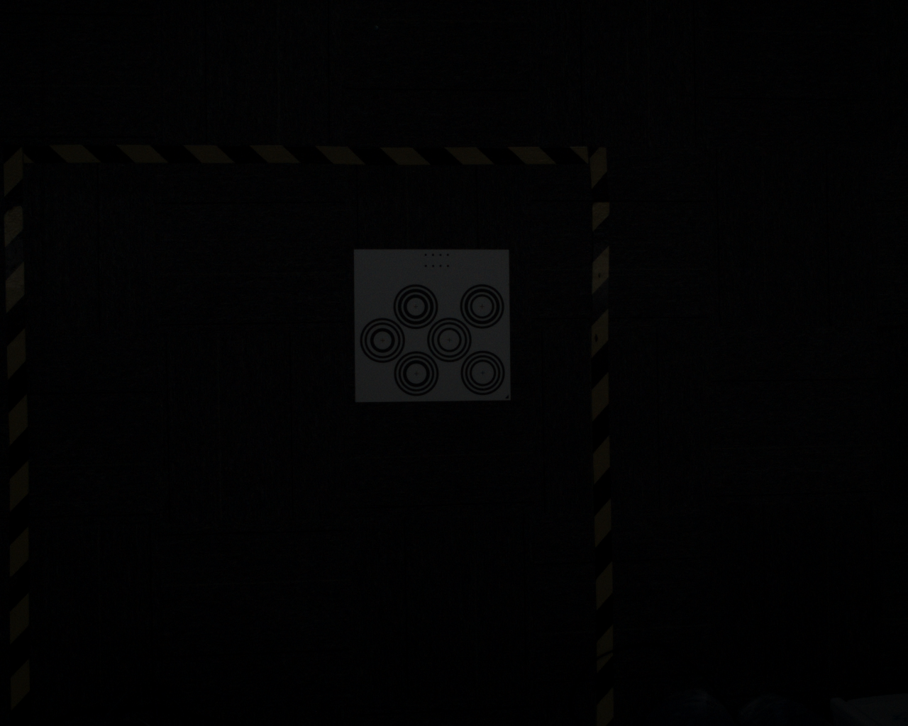 | 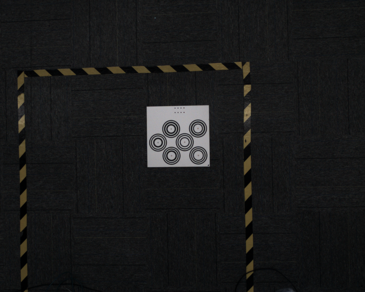 | 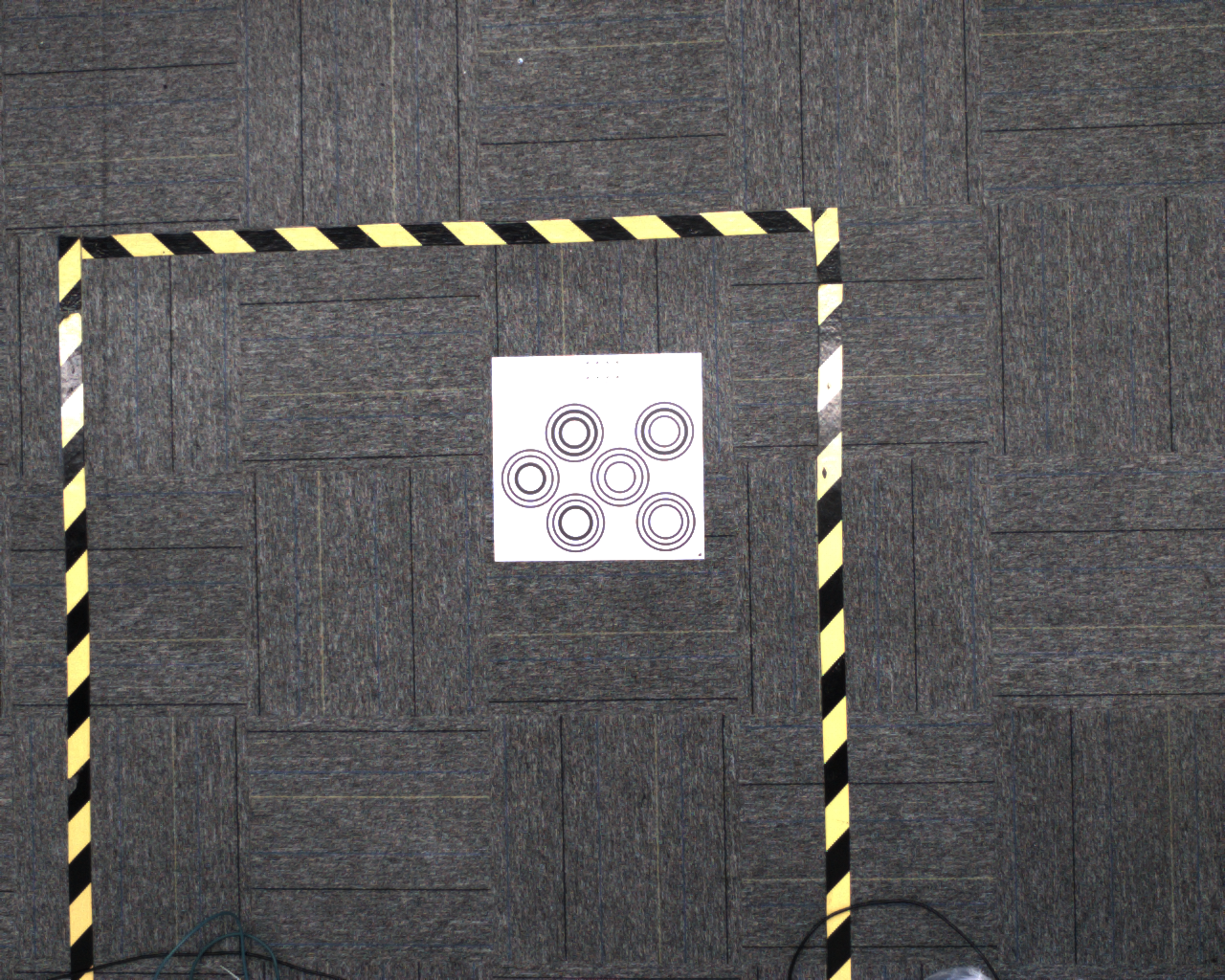 |
|---|---|---|
| Underexposed | Correctly exposed | Overexposed |
2.11.2 Show Overexposed Areas
With “Show Overexposed Areas” enabled, the visualization window highlights overexposed areas in the current image. Use this to judge whether the exposure time and projection brightness are suitable.
2.11.3 Continuous Capture
To observe imaging continuously, click “Continuous Capture”. The camera keeps capturing and updates the visualization window. Click “Cancel Capture” to stop.
3. Camera Accuracy
3.1 Check Camera Accuracy
- Place the calibration board in the camera's field of view and click “Camera Accuracy” on the configuration screen.
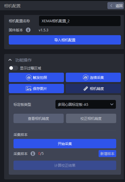
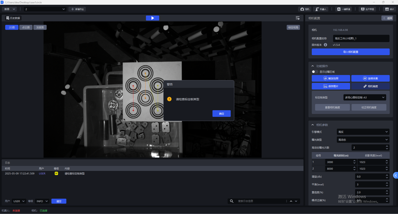
- Select the same calibration board type as the physical board. If they do not match, the software displays a “Check Calibration Board Type” warning.
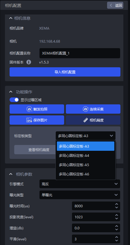
- After selecting the correct board type, click “Check Camera Accuracy”. PickWiz automatically calculates the current camera accuracy.
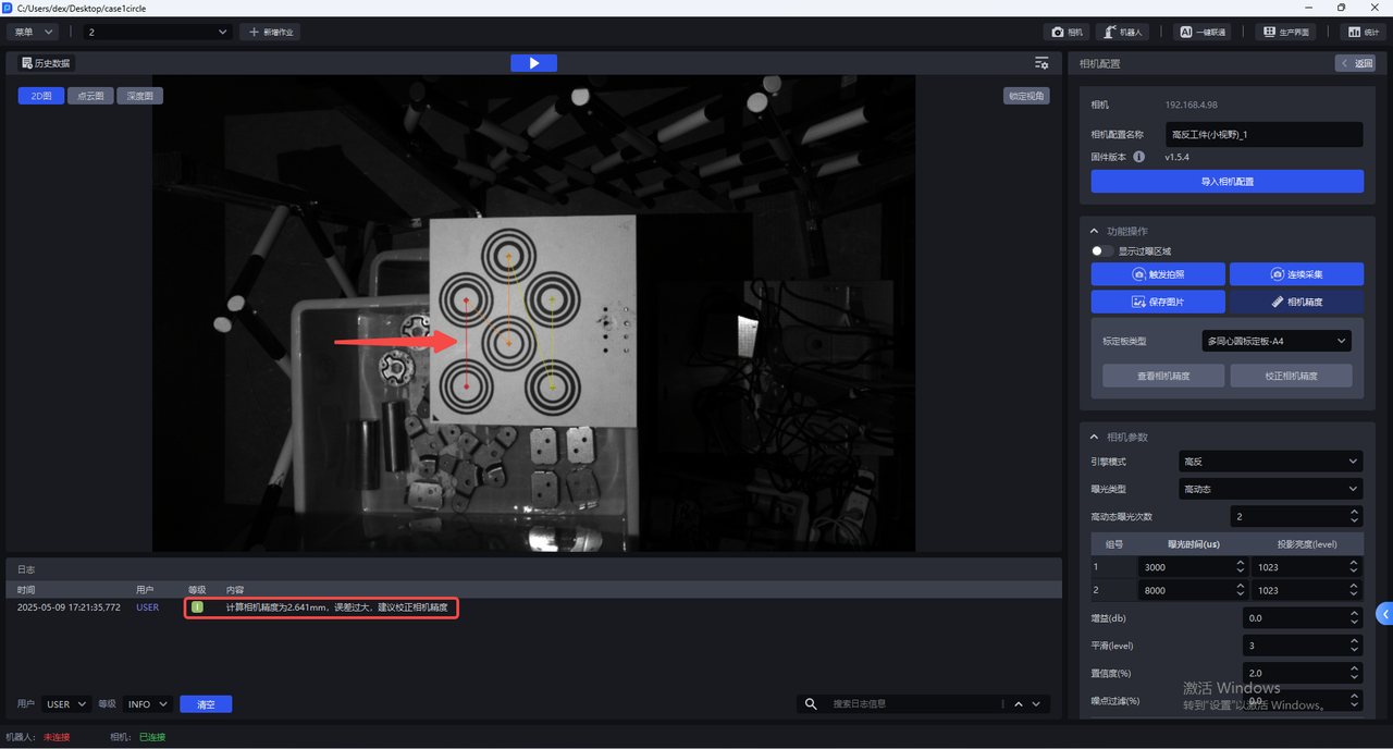
For KINGFISHER series cameras, an accuracy error below 0.8 px usually meets the requirement. The actual acceptance threshold depends on the project requirements. If the software reports excessive error, correct camera accuracy before continuing to tune parameters.
3.2 Correct Camera Accuracy
During normal use and after correcting extrinsic parameters, verify that the current camera accuracy meets requirements. Correct it again when:
- The error is abnormal when checking camera accuracy.
- The point cloud captured by the camera has substantial fluctuations.
- You have changed the camera's mounting position, lens, or related hardware.
Checks Before Correction
Before correction, enable “Show Overexposed Areas” and check whether a single exposure produces a normal image. If any area is overexposed, adjust the single-exposure time before capturing calibration samples. After correction, return the camera imaging parameters to their original configuration.
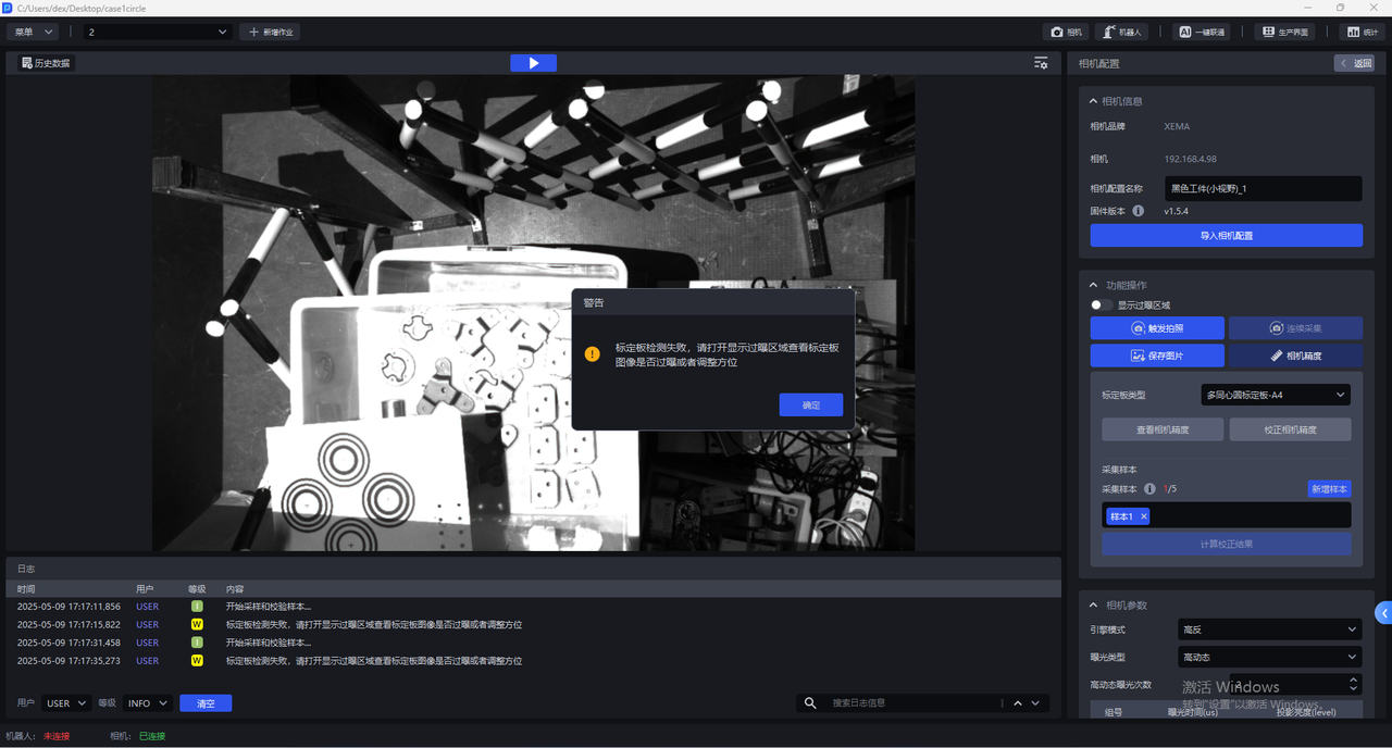
- Click “Camera Accuracy” on the camera configuration screen.
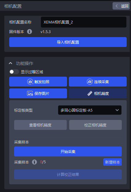
- Select the same calibration board type as the physical board.
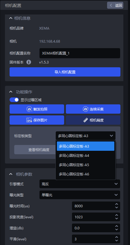
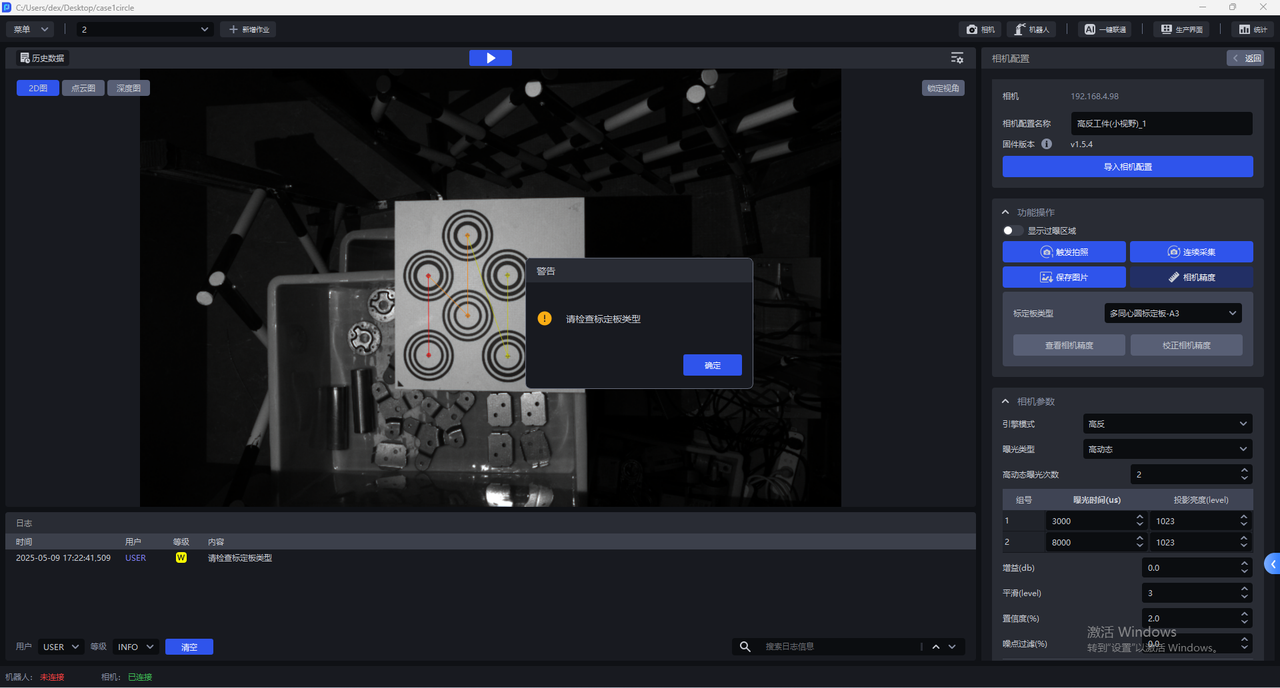
- After selecting the correct board type, click “Correct Camera Accuracy”.
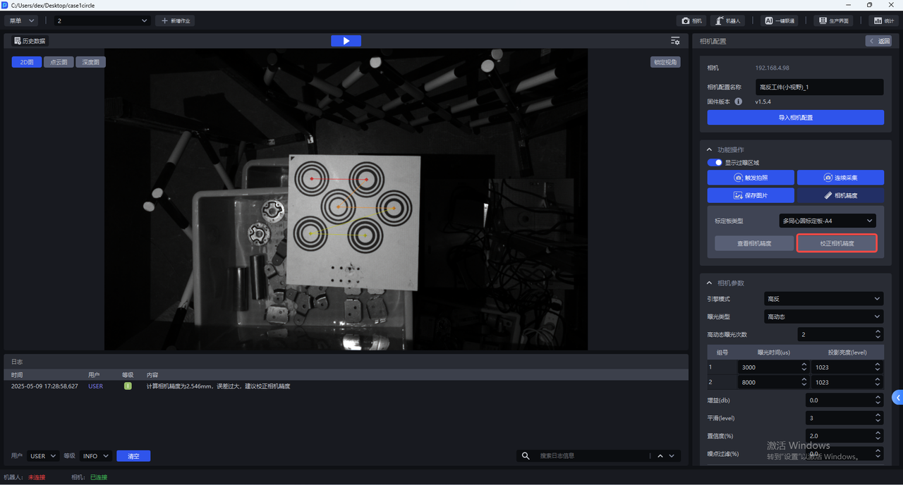
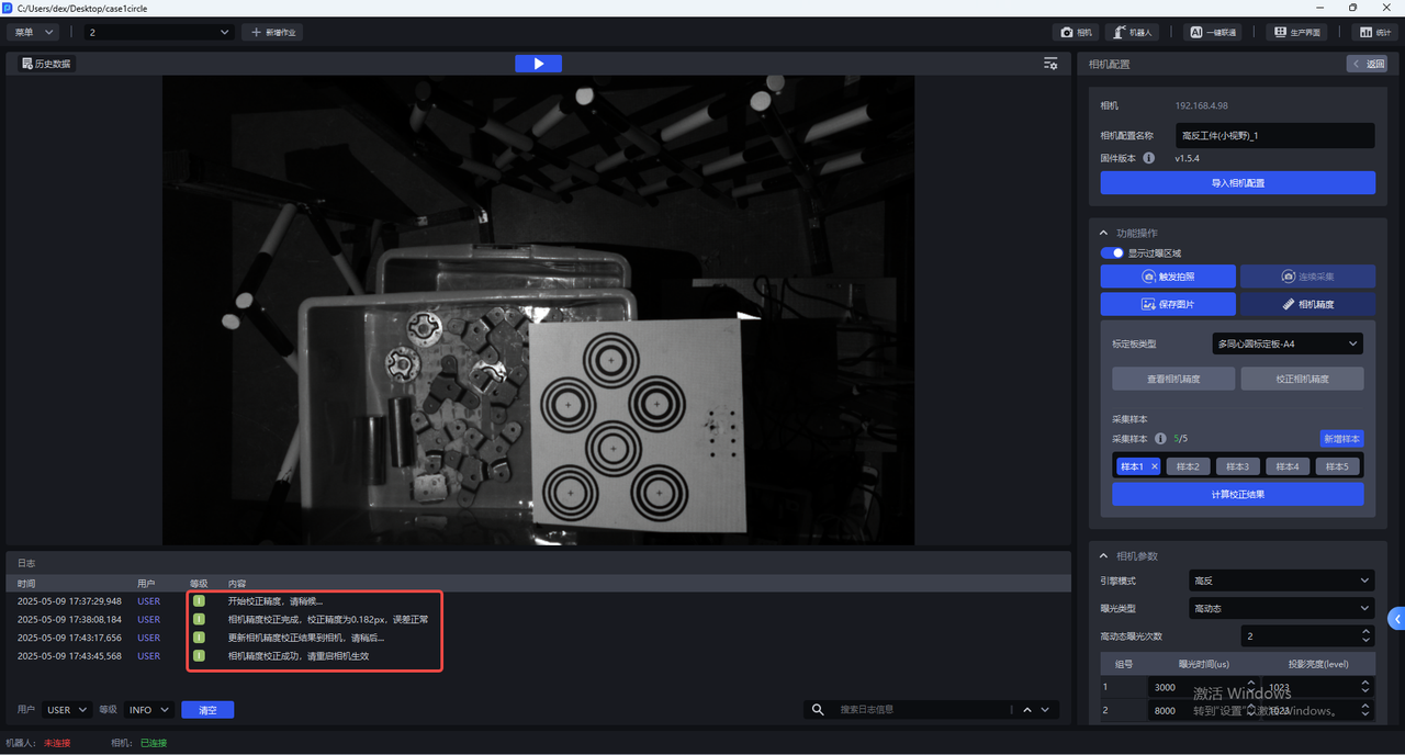
- Place the calibration board horizontally at the center of the camera's field of view and click “Add Sample”. The camera captures and validates the sample. Valid samples appear in the “Captured Samples” list.
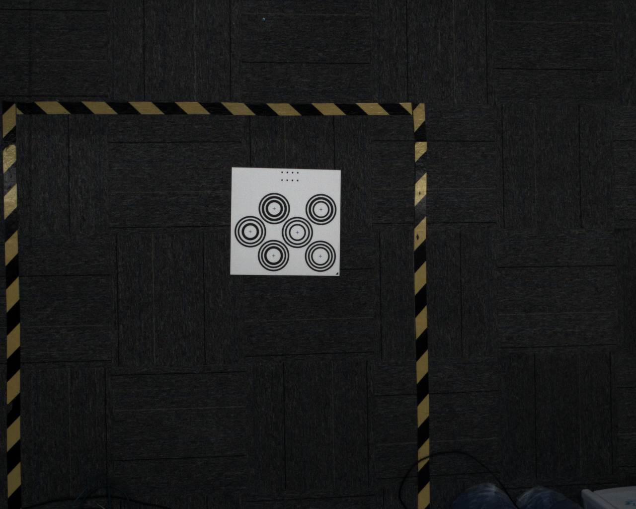
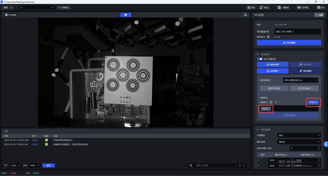
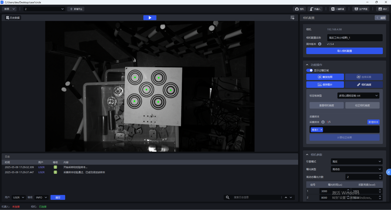
Click “Sample x” to view a captured sample. When validation succeeds, the centers of all concentric circles on the calibration board appear green.
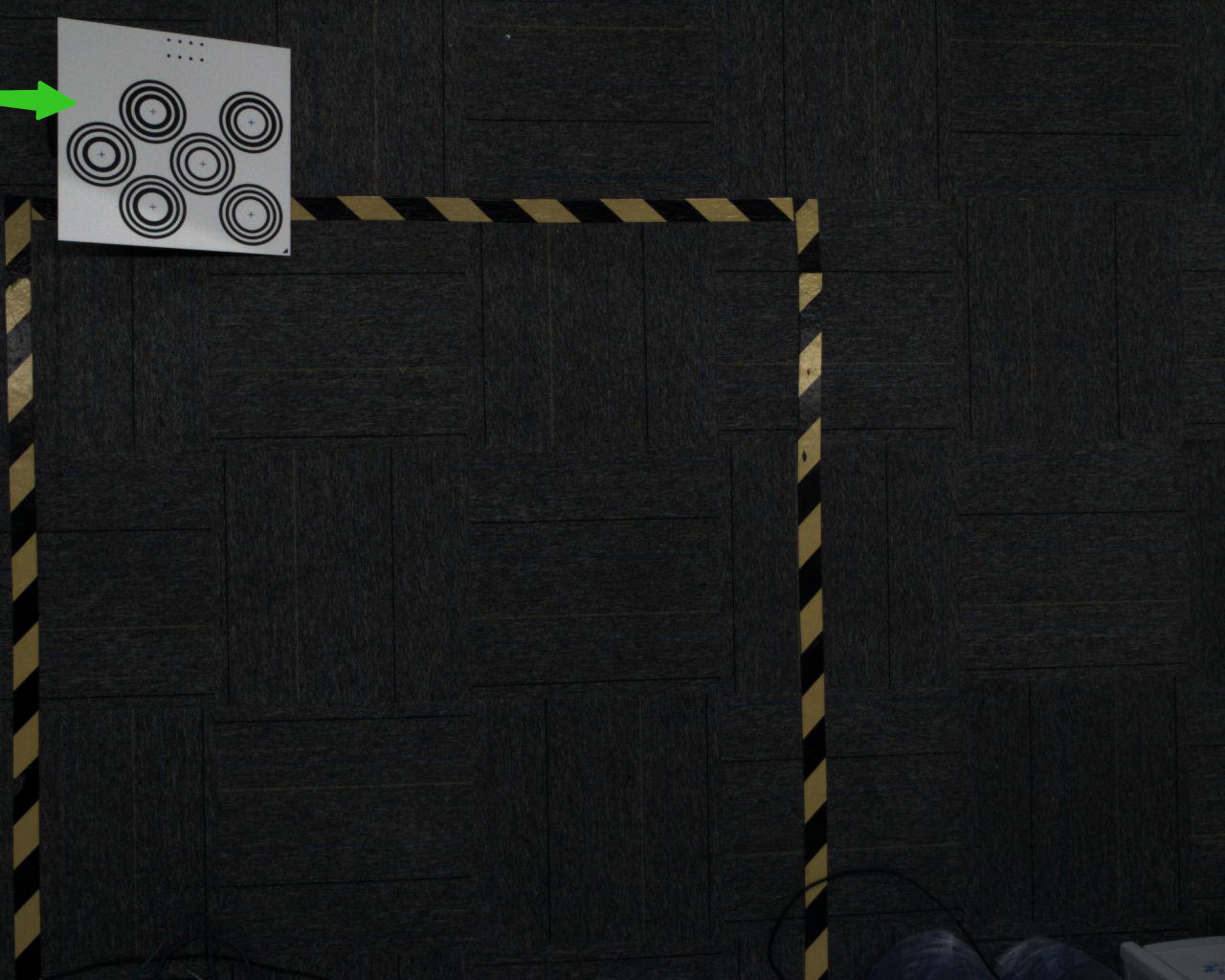
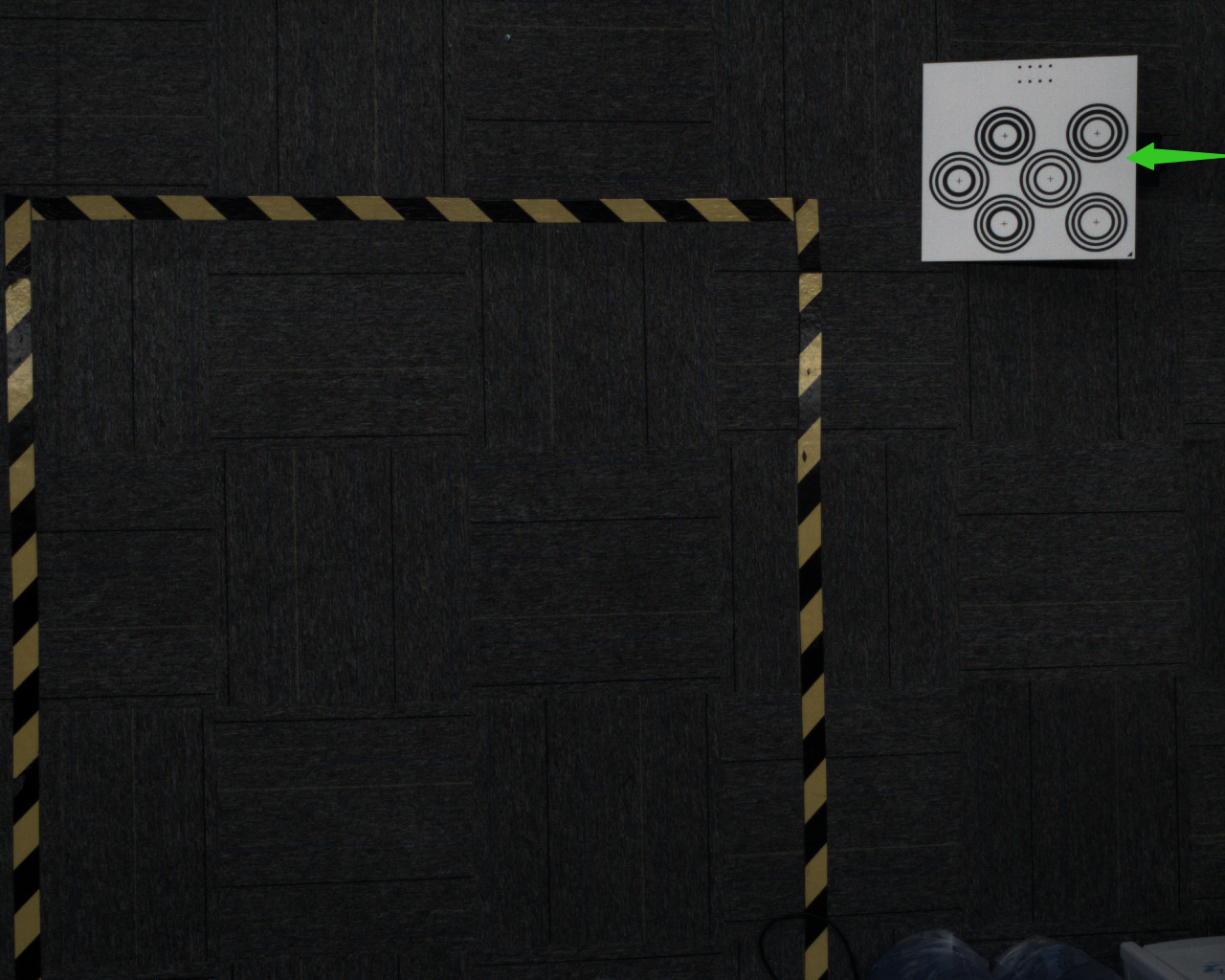
- Move the calibration board to each of the four corners of the camera's field of view, adding a sample at each corner. You can raise the board at each corner to give it an angle of 15°–30°; avoid tilting it too much or too little.
 |  | 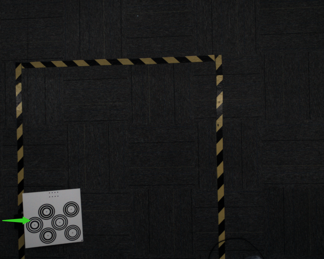 | 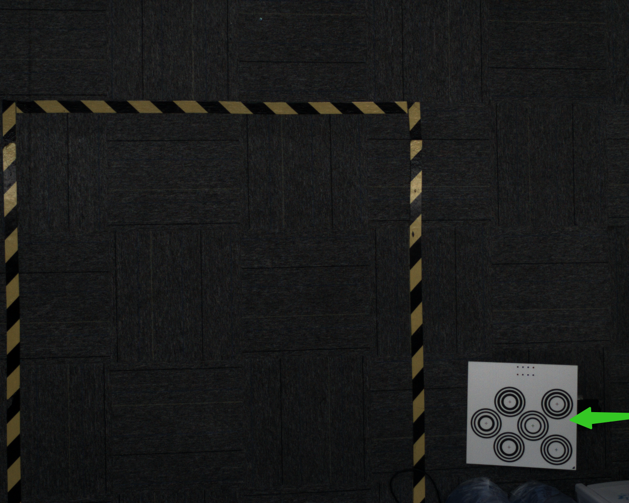 |
|---|
- After adding one center sample and four corner samples, 5 in total, click “Calculate Correction Result”.
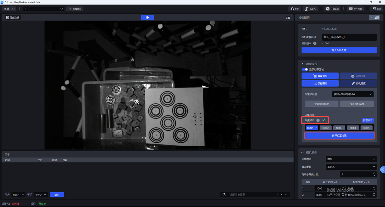
- When correction finishes, the software asks whether to overwrite the current camera parameter configuration, with a message stating that camera accuracy correction is complete, the corrected accuracy is x, and the error is normal.
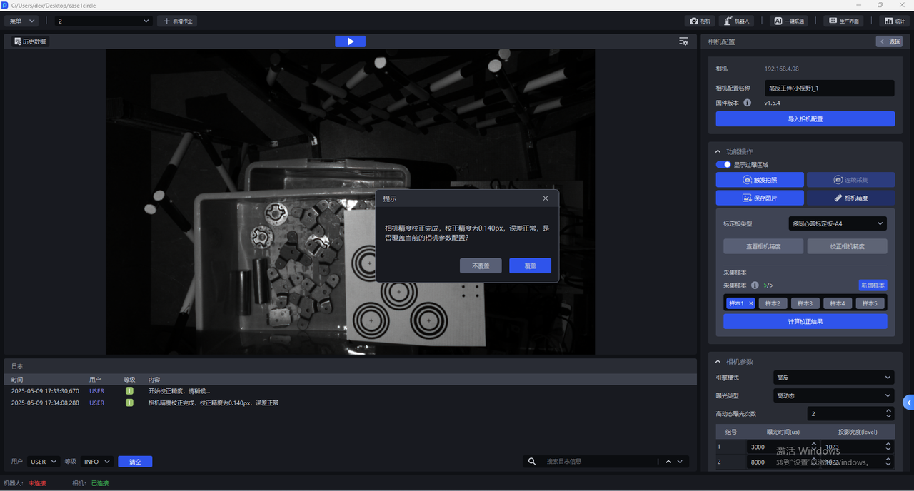
If you choose to overwrite the current camera parameter configuration, the correction result is written to the camera. The camera usually needs to restart before the result takes effect.
4. Camera Parameter Tuning
Tune imaging first, the point cloud second, and overlaid output last. Change one parameter at a time and trigger a capture. Check the 2D images, point cloud, and depth image together, and continue only after confirming a stable improvement.
KINGFISHER is a stereo camera with an independent parameter template for each eye. Set the parameters in the appropriate template and keep the left and right images consistent. Each unit is physically a 2D camera, so tuning mainly adjusts exposure, white balance, and imaging quality. Good imaging is essential for subsequent point cloud quality and accuracy.