
Visual Parameter Configuration
5. Visual Parameter Configuration
This case determines the pose of a single target through point cloud registration. Parameter tuning focuses on useful features, point cloud quality, coarse and fine matching, and the validity of the positioning result, rather than the quality of 2D segmentation.
5.1 Establish a Baseline with the Default Configuration
- Select the configured Camera, Robot, Target, End-effector, calibration, and ROI.
- Open the visual parameter configuration automatically generated when the new Task was created.
- Run the default parameters using historical data with complete positioning features and a normal incoming target position.
- Record whether each processing stage succeeds, the template matching position, the positioning point direction, and the time taken.
- Change only parameters related to the current issue. Click Apply, then retest with the same data.
Do Not Add Filters That Depend on 2D Recognition
This Task has no 2D Instance Segmentation stage. Do not use filters based on recognition results such as mask area or 2D bounding box area. An image or the word “instance” appearing in the visualization does not mean that a 2D model performed recognition.
5.2 Inspect the Point Cloud Used for Registration
5.2.1 Check the ROI and Denoising First
- Confirm that the ROI retains only the useful features needed for the current target, with a reasonable margin.
- Compare the raw and preprocessed Point Clouds to check for remaining neighboring targets, supports, or background points.
- Select functions such as outlier removal and cluster denoising according to the actual noise pattern.
- When filtering by height or distance, confirm that steps, groove bottoms, and edges have not also been removed.
- After processing, inspect the geometric constraints from multiple angles to ensure the template has not become a plane lacking positioning features.
For preprocessing methods, see the 3D Preprocessing Function Configuration Guide.
5.2.2 Distinguish Between the Three Downsampling Stages
| Configuration location | Data processed | What to verify |
|---|---|---|
| 3D preprocessing: Point Cloud Downsampling | The Point Cloud passed to subsequent calculations | Whether it reduces computation while preserving positioning features |
| Point Cloud Matching: Model Point Cloud Downsampling Size | The template Point Cloud used for Coarse Matching | Template point count and Coarse Matching success rate |
| 3D preprocessing: Point Cloud Downsampling (Target Point Cloud) | The Scene Target Point Cloud used for Fine Matching | Fine Matching time and final positioning accuracy |
Do not use the same value for all three merely because their names are similar. In the existing V1.9.0 guides, the default point spacing for ordinary Point Cloud Downsampling is 5 mm, the default for Target Point Cloud Downsampling is 1 mm, and the default Model Point Cloud Downsampling Size is 5 mm. These are starting points for their respective parameters, not a single recommended accuracy for aluminum ingot marking.
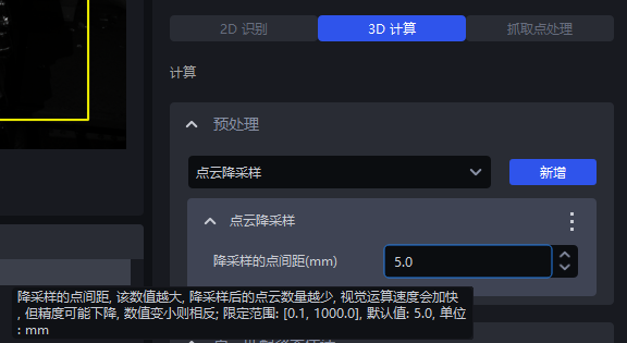
The image shows where to configure ordinary Point Cloud Downsampling. After an adjustment, compare edges and grooves before and after processing to confirm that positioning features remain, then compare the time taken. The 5.0 mm shown does not represent the final positioning error.
For the processing stages and settings, see the 3D Preprocessing Function Configuration Guide and the Point Cloud Matching Pose Estimation Configuration Guide.
5.3 Verify Coarse Point Cloud Matching
- Display the Target template in the 3D visualization and check whether it lies on the correct structure.
- Check the orientation of the template against the Scene, paying particular attention to in-plane shifts, repeated grooves, and symmetric orientations.
- If the template has too many points and the logs show that sampling takes excessive time, adjust Model Point Cloud Downsampling Size.
- When adjusting Repeated Sampling Ratio Coefficient, compare both success rate and time taken, rather than speed alone.
- If the incoming target orientation is constrained and symmetry causes ambiguity, consider Pose Angle Prior, first checking the ROI coordinate axes.
Contour-Based Coarse Matching
If the geometric contour is stable, consider “Enable Contour Mode.” As required by the guide, also configure “Point Cloud Contour Extraction” in 3D preprocessing and confirm that the logs show valid contour points. Switching modes alone cannot restore features missing from the raw Point Cloud.
For the angle-prior format and contour mode, see the Point Cloud Matching Pose Estimation Configuration Guide.
5.4 Verify Fine Matching and Positioning Error
Once the Coarse Matching orientation and position are approximately correct, inspect the Fine Matching result from Object Pose Correction.
- Fine Matching Search Radius: The default in the V1.9.0 guide is 10 mm. A radius that is too small may leave too few valid corresponding points; one that is too large may match the wrong structure.
- Fine Matching Search Mode: Compare point-to-point, point-to-plane, or combined methods according to the Point Cloud features, recording both accuracy and time taken.
- Contour-Related Settings: Consider these only when the contour is distinctive and stable, and inspect the contour extraction result first.
- Save Fine Matching Data: Enable this during diagnosis to compare how well the template fits before and after correction.
Inspect the template from the front, side, and an oblique angle. Do not judge marking accuracy solely by a “match successful” display or a single score. If Coarse Matching places the template on the wrong groove, correct the features and ROI first instead of expecting Fine Matching to find the true target automatically.
Units and Metrics
Template file units, downsampling point spacing, search radius, and final positioning error are different concepts. Fields may use millimeters or meters; check each one. The search radius is also not the final marking positioning accuracy.
5.5 Empty-ROI Detection and Positioning Pose Filtering
5.5.1 Validate the No-Target State
Use data both with and without an aluminum ingot to check the empty-ROI determination in the default workflow. Set the Threshold according to the actual point-count distribution, and verify how the equipment responds after receiving a no-target or failure status.
Changes to downsampling and the ROI affect point counts, so retest empty-ROI detection whenever they change. If the ROI contains Point Cloud data from supports or a conveyor, it may appear nonempty even without an aluminum ingot. A sufficient point count does not mean that the correct target was recognized.
For the meaning of the Threshold, see the Empty ROI Determination Configuration Guide.
5.5.2 Check Output Position, Angle, and Match Quality
- Use Filter by Fine Matching Score to exclude results with insufficient match quality, validating it with both correct and incorrect samples.
- Use Filter by Pick Pose Angle Range to constrain the tool direction. Check the ROI axes, positive and negative directions, and tool axes.
- Use Filter Pick Points Outside the ROI 3D Type Area to constrain the positioning point. Confirm how the marking positioning point relates to the selected work area or pick area.
- When enabling tool collision filtering, use a model with correct dimensions and coordinates that meets the function’s requirements, and validate borderline cases.
Looser filter conditions are not necessarily better. If a positioning point is filtered out, identify the cause first instead of disabling the filter simply to obtain an output. For instructions, see the Pick Point Filtering Function Configuration Guide.
5.6 Example Approach to Optimizing Cycle Time Using Logs
The original reference debugging process showed that the target could be matched, but the Scene Point Cloud had far more points than the template Point Cloud, and Fine Matching took considerable time. Reproduce this analysis method in the following order:
- Confirm that the template fits and the positioning point is correct, then save the current result as a baseline.
- Switch to DEBUG logs and distinguish the time spent on acquisition, preprocessing, Coarse Matching, Fine Matching, and saving.
- Based on the actual bottleneck, choose downsampling for the Scene Point Cloud or the Fine Matching Point Cloud. Do not change all sampling parameters at once.
- After applying the change, run the same historical data again.
- Verify positioning error and stability before comparing the time taken.
- Run regression tests with edge-position, tilted, surface-variation, and empty-input samples. Save the configuration for operation only after the tests pass.
The change in time shown in the original example applies only to its test conditions and is not a performance commitment for this case. The next chapter verifies whether the visual result actually meets the marking process requirements.
Return to Case Overview · Previous Chapter: Point Cloud Template and Marking Positioning Point Configuration · Next Chapter: Operation and Acceptance