
Point Cloud Template and Target Configuration
4. Point Cloud Template and Target Configuration
This chapter associates the prepared CAD model, keypoints, point cloud template, and Visual Model with the same cylinder Target, and configures its Pick Points. First establish a consistent coordinate relationship between the model and template, then adjust the pick position. Do not use a Pick Point offset to conceal a template error.
4.1 Add a Target and Establish the Mesh Reference
- On the Target page, click Add Target and use an easily recognizable general name, such as “Cylinder”.
- Prepare a PLY mesh file that matches the actual cylinder, and check its main dimensions and file units.
- Use the mesh processing function to Normalize Mesh File, then check the normalized dimensions, center, and axis directions.
- Export the normalized mesh as the common reference for subsequent keypoint creation, template alignment, and model training, and assign it to the current Target.
Normalization and Associated Files
A mesh usually needs to be normalized only once. After normalizing it again or readjusting its pose, do not assume the original keypoints, point cloud template, and Pick Points remain valid. Recheck the coordinate relationships across the complete set of files and their compatibility with the model.
For detailed instructions, see the Point Cloud Template Creation Guide.
4.2 Create a Point Cloud Template
4.2.1 Select a Template Source
Choose a template based on the cylinder surfaces that the Camera can reliably see during normal operation. Do not include the invisible rear surface, background that may change, or adjacent cylinders in the matching region.
| Source | Conditions for Use | Key Checks for This Case |
|---|---|---|
| Generated from a normalized mesh | The CAD model closely matches the physical Target and the point cloud actually visible | For a fixed incoming pose, “Current View Only” may be used; the view must closely match the actual Camera view |
| Generated from Camera captures | Real imaging features are needed, and the background can be kept stable | Nothing except the Target may change between the captures with and without the Target |
| Point cloud captured within a 3D region | One cylinder can be selected independently in the Scene | Check the boundaries from multiple angles and exclude the tray, fixture, and adjacent cylinders |
| Existing template file | The source, Target model, and coordinate relationship can be verified | Do not treat a file as a usable template merely because it can be imported |
Historical Data Sources
Point clouds in existing historical data can serve as sources for analysis and templates, but you must confirm what the selected point cloud represents and which coordinate system it uses. Do not apply the “Generate Template from Historical Data” entry point, which is only suitable for image matching Tasks, to this case. Follow the Point Cloud Template Creation Guide for the creation entry points and their applicable scope.
4.2.2 Capture and Select Effective Features
- Place one cylinder in its actual incoming orientation so that its effective surfaces are within the normal imaging range.
- Generate a template using the selected method, retaining only the effective point cloud of that cylinder.
- Check whether the outer contour, steps, holes, or other directional features that actually exist are continuous, stable, and distinctive.
- Exclude stray points caused by reflections, supports, and adjacent Targets. Do not remove features needed to determine orientation while removing noise.
- Use multiple captures to check whether the selected region is stable, then apply appropriate downsampling according to accuracy and Cycle time requirements.
- Export the template and retain the original version without downsampling for comparison and reprocessing.
For neatly arranged cylinders, the template does not need to include every surface. What matters more is that the selected features remain visible across the permitted changes in position and angle. If an end face or side is often occluded during operation, it should not be the sole basis for determining orientation.
The following two images show a ring-shaped demonstration part from the original reference material. They illustrate 3D region selection and template generation; they do not represent the complete shape or template dimensions of the cylinder in this case.
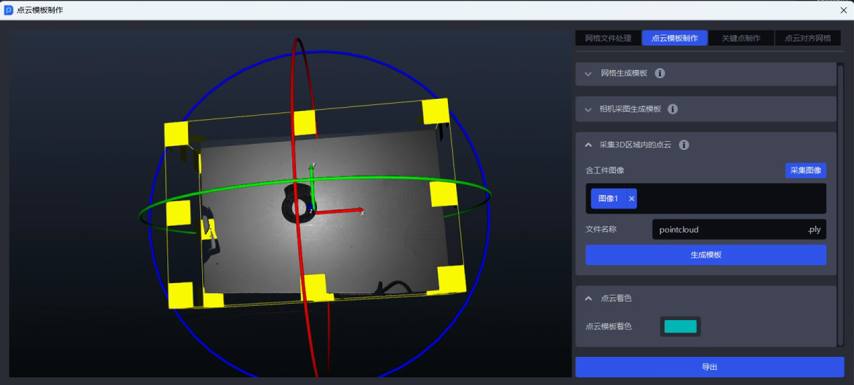
The image above shows the initial region; do not retain the entire tabletop. Shrink and adjust the 3D box, check its thickness from the side, and exclude the support surface and other objects before clicking Generate Template.
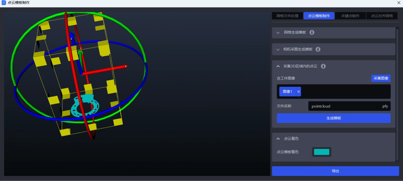
The cyan area in the image below is the generated result. Check that only the Target features remain, then export it and align the coordinates. The ability to generate a template does not mean it is already aligned with the mesh and keypoints.
4.3 Create Keypoints and Unify Coordinate Systems
4.3.1 Create Matching Keypoints
- Import the same normalized mesh in Keypoint Creation.
- Select downsampling or Target contour generation according to the actual features. For incoming Targets viewed from a fixed angle, you may assess the “Current View Only” method.
- Check the keypoint coverage to ensure it can express the cylinder’s position and orientation, rather than being concentrated in a local region with little distinctive information.
- Export the keypoint file and keep it paired with the subsequent model training configuration.
A common filename is keypoint_128.ply, but verification should be based on the file’s content and its pairing with the other files, not on its name.
4.3.2 Align the Template with the Normalized Mesh
- Load the normalized mesh and the point cloud template to be used in Align Point Cloud to Mesh.
- Run Calculate Alignment and check whether the cylinder contour and effective features fit.
- Check their overlap from the front, side, and oblique views to rule out reversed front and back faces or mismatched symmetrical directions.
- Check that the visible surface represented by the template is consistent with the keypoint configuration, then export the alignment result.
- Import the final file into the Target, and check the software’s coordinate center validation prompt and visualization again.
Centering Is Not Alignment
A point cloud centered at the coordinate origin does not necessarily have the same axis directions as the CAD model and keypoints. Alignment is complete only when the dimensions, origins, directions, and corresponding surfaces of all three are correct. Do not center each file separately and then use them together without checking.
For operational details, see the Point Cloud Template Creation Guide.
4.4 Configure the Model and Pattern Mask
- Import the normalized Mesh File and final Point Cloud File into the Target.
- Enable Custom Keypoints and import the keypoint file paired with this mesh and Visual Model.
- If a separate fine matching template is needed, import the aligned Fine Matching Point Cloud Template; a separate configuration is not required in every case.
- Configure the Pattern Mask according to how the cylinders are actually arranged. For regular rows and columns with small spacing, you may assess “Tightly Packed”; use “Custom Pattern Mask” when a more detailed representation is needed.
- Check the Target properties and the environment and texture data required for training.
- Train the corresponding Visual Model through one-click integration, or select a model already verified to match the current Target, keypoints, and Pattern Mask.
- Set Maximum Number of Model Detections according to the actual number of instances to identify. For neatly arranged incoming Targets, validation can begin with a value slightly greater than the actual number in one layer, while also checking Inference time.
For the complete model training procedure, see the One-Click Integration User Guide. For field descriptions, see the Target Configuration Guide.
Model Iteration
First validate the model using representative normal incoming Targets, then check variations such as edge positions, permitted tilt, missing Targets, and occlusion. If additional training data is needed, use only approved environment and texture data. Do not use raw screenshots containing customer identifiers, personal information, or internal paths directly in public instructions.
4.5 Set Cylinder Pick Points
A newly added general Target has no Pick Points by default; add them manually.
- Add a Pick Point to the Target and initially configure only one clearly defined picking method.
- Adjust the Pick Point position according to the actual gripping area. Set the position relative to the aligned Target model, not relative to the incoming Target’s position in any single Camera capture.
- Adjust the Pick Point orientation so the End-effector approaches the cylinder as required by the process. Check the pose axis directions against the actual TCP definition; do not rely solely on whether the coordinate origin lies on the surface.
- Check the relationship between the gripper and cylinder from different views, and confirm that the approach direction does not pass through the Target or nearby materials.
- Save the Target and select this configuration in the Task information.
- During subsequent operation, check that the Pick Point translates and rotates correctly with the cylinder’s pose before considering additional feasible Pick Points.
Picking Direction and Filter Conditions
The Pick Point direction must be consistent with the ROI axis, positive and negative directions, and picking pose axis used by the subsequent angle filter. If the process requires side picking, check the angle constraints as well. Do not allow abnormal poses through merely by relaxing or disabling the filter.
4.6 Configuration Completion Checks
- The mesh, keypoints, and template come from the same configuration and have consistent dimensions, origins, and directions.
- The template contains only stable, visible cylinder features, with no adjacent Targets or background.
- Custom keypoints are enabled, and the Visual Model is paired with the keypoints and Pattern Mask.
- At least one Target Pick Point has been checked, with a position and orientation that meet the tool and process requirements.
- The corresponding Target is selected for the current Task; do not perform automatic picking before visual acceptance is complete.
Return to Case Overview · Previous Chapter: Create a Task and Configure the Basics · Next Chapter: Configure Vision Parameters