
Point Cloud Template Creation Guide
PickWiz provides four functions for creating point cloud templates: mesh file processing, point cloud template creation, keypoint creation, and point cloud to mesh alignment. This guide first explains how to use the software, then covers template selection principles and typical cases to help you choose a method for your target and scene.
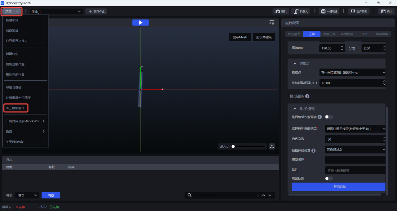
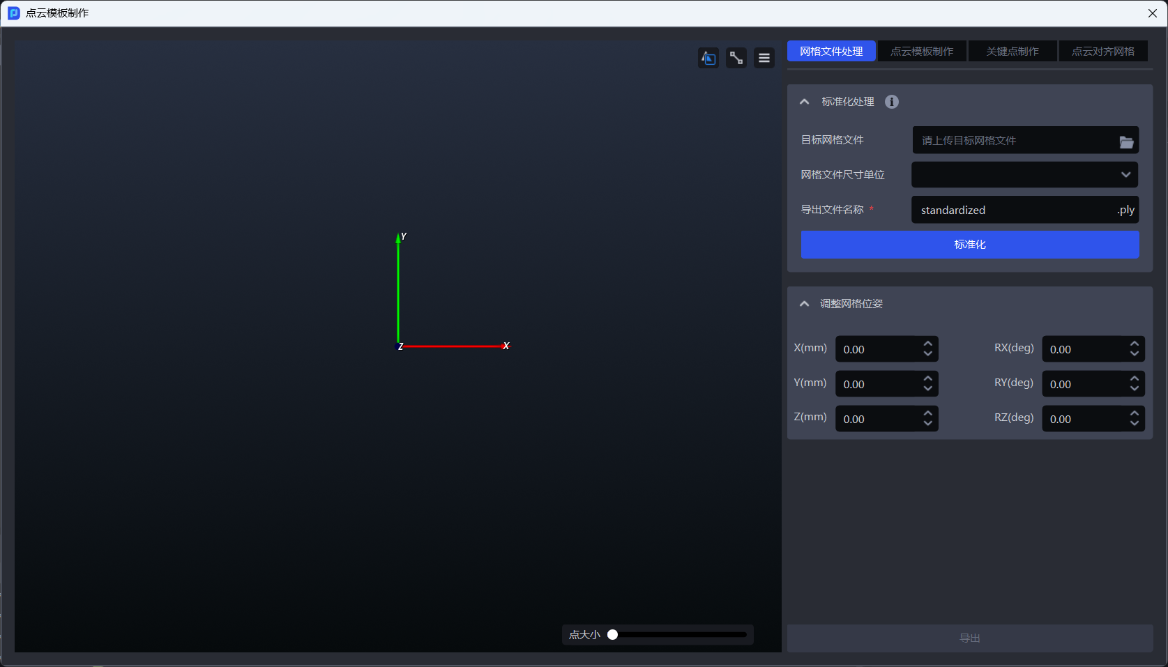
On the main screen, select Menu > Create Point Cloud Template to open the point cloud template creation window.
Use this checklist when creating a point cloud template. The sections below explain how to assess each item and perform the relevant operations.
- Assess before creating: Confirm the scene type, point cloud quality, and variation in target pose.
- Check target characteristics: Examine size, symmetry, self-occlusion, 3D shape, and features such as recesses, convex surfaces, or approximately planar areas.
- Apply template principles: Balance feature salience, stability, uniqueness, redundancy, and computational efficiency.
- Choose a creation method: Select mesh generation, camera capture, 3D region selection, or historical data according to the point cloud source.
- Validate and export: Check the number of points and coordinate alignment, run a matching test, and update the template periodically as the target changes.
1. Assess Before Creating a Template
1.1 Define the Template’s Purpose
A point cloud template describes the shape, structure, and key features of a target under ideal conditions. After the template is assigned to a target, the system performs 3D matching against the target point cloud captured by the camera in real time to determine the target pose.
A template can describe the entire target or only a stable, distinguishable region. Confirm the following before creating one:
- Scene type: A neatly arranged scene usually requires only the fixed visible surfaces. For a randomly arranged scene, cover regions that can be imaged reliably across different target poses.
- Matching purpose: For coarse matching, prioritize recognizability and speed. For fine matching, a more complete, denser point cloud can improve the pose.
- Template source: A standardized mesh, camera capture, a selected 3D region, or historical data.
- Coordinate relationship: A template created from camera images usually uses the camera coordinate system as its origin and must subsequently be aligned with the standardized mesh.
1.2 Check Prerequisites
| Check | How to assess | Recommendation |
|---|---|---|
| Target pose variation | Limited poses: the target appears on only a few fixed faces; arbitrary poses: the target may appear at different angles | For neatly arranged scenes, use a point cloud of the fixed visible surfaces. For randomly arranged scenes, use multiview capture or CAD simulation to assess how often regions are visible, and prioritize regions that image reliably in most poses. |
| Camera point cloud quality | Check completeness, depth continuity, noise, and occlusion | For reflective or translucent materials, improve lighting or use diffuse light or a polarizing filter. Capture at the camera’s optimal working distance, and reduce noise through filtering, outlier removal, and processing by region. |
| Background stability | Compare images captured with and without the target | When creating a template from camera images, keep the viewpoint, camera parameters, and everything in the scene other than the target unchanged between captures. |
| Point cloud size | Check the number of template points and the density of local features | As a general guideline, keep the template at or below 50000 points. For large targets, retain density around features such as edges and holes while sampling planar regions more sparsely. If a small target has fewer than 200 effective points, increase point cloud density or lower the camera height. |
1.3 Select Regions Based on Target Characteristics
| Target characteristic | Identifying features | Template selection recommendation |
|---|---|---|
| Self-occlusion or layering | Multiple nested layers, complex curved surfaces, or targets occluding one another | Use the stable point cloud after system processing. Prioritize features that are less likely to be occluded, such as the outer contour and fixed holes. For severe occlusion, create local templates from separate viewpoints. |
| Pronounced 3D shape | Height differences, steps, edges, or curved surface variations | Select regions that can actually be imaged, and exclude points on the back. Increase density around edges and corners as needed, and sample planar regions more sparsely. |
| Symmetry or rotational symmetry | Similar appearance from left to right, front to back, or after rotation | When using a keypoint model, align the point cloud template, keypoints, and CAD center point precisely to avoid ambiguity from mirroring or orientation. |
| Recesses, deep holes, or grooves | Recessed regions are prone to missing points or viewpoint effects | Prioritize the outer contour. Assess the stability of side points across multiple viewpoints, and retain only necessary features on the bottom. If quality is unstable, use an edge contour with a small number of feature points. |
| Convex curved surface or high reflectivity | Reflections at curved edges and discontinuous point clouds | Prioritize complete, stable point clouds. If overall quality is insufficient, retain only highly distinctive features such as markers and edges. Create front and back templates if necessary. |
| Approximately planar | Little significant depth variation inside the target | Concentrate points along the outer contour and edges. If tilting blurs the edges, use keypoints or adjust the lighting and capture angle. |
| Prone to wear or deformation | Shape and occlusion relationships change during use | Periodically review point cloud quality, occlusion, and 3D shape. Recapture and update the template when necessary. |
1.4 Template Selection Principles
Template features should meet all of the following requirements:
- Salience: Prioritize easily recognized features such as edges, corners, holes, textures, and stable raised or recessed surfaces.
- Stability: Features should remain visible and retain a stable shape under changes in lighting, viewpoint, and permitted pose.
- Uniqueness: Features should distinguish the target from other targets and the background, avoiding false matches caused by repeated structures.
- Redundancy: Retain enough evenly distributed points in the effective region to allow matching when some points are occluded or missing.
- Repeatability: Repeated captures and different poses should reliably produce similar point clouds.
- Computational efficiency: Limit the number of points while meeting accuracy requirements. Exclude irrelevant points, overly dense planar points, and background points that increase computation.
2. Mesh File Processing
A mesh file is usually a 3D CAD model of the target. It is used to connect visual model training, point cloud template generation, keypoint generation, and point cloud to mesh alignment in one workflow. Currently, only ply files are supported.
After uploading the mesh file, select meters (m) or millimeters (mm) under Mesh File Size Unit. If you are unsure of the unit, leave it unselected; the system will determine it from the file and convert it automatically. Then click Standardize Mesh File.
Standardize Mesh File
Standardization performs the following operations:
- Aligns the mesh file with the coordinate center.
- Simplifies Mesh faces.
- Adjusts the target pose to correct misalignment between the target and coordinate system.
- Converts dimensions to meters (m).
Warning
Each click of Standardize Mesh File standardizes the result of the previous operation again. A mesh file usually needs to be standardized only once.
After standardization, you can adjust the mesh pose and inspect the result in the left viewport. To upload it to a target in the current task, select Export > Target in Current Task, select the target, and click Sync to Target. To create a point cloud template or perform point cloud to mesh alignment, export the standardized mesh file locally.
3. Create a Point Cloud Template
3.1 Choose a Creation Method
| Method | Operation | Suitable scene |
|---|---|---|
| Generate template from mesh | Downsample a standardized mesh file to generate a point cloud template in one step | The actual point cloud captured by the camera closely matches the point cloud generated from the mesh. |
| Generate template from camera images | Capture images with and without the target, then generate the target point cloud from their difference | The actual point cloud does not closely match the mesh point cloud. |
| Capture point cloud within a 3D region | Select the target region with a 3D bounding box in a point cloud image containing the target | A local part of the target needs to be extracted directly from the current camera view. |
| Generate template from historical data | Restore a point cloud from a complete historical data set and select the target region | “Loading and unloading of neatly arranged plane type target objects (image matching)” and “Plane type Target positioned assembly (image matching only).” |
3.2 Generate a Template from a Mesh
Function: Downsamples an imported standardized mesh file to generate a template. Two modes are available:
Generate Template: Uses the entire point cloud of the standardized mesh. Suitable for most scenes.Generate Template (Current View Only): Uses only mesh points visible from the current viewpoint. Suitable for neatly arranged scenes with a fixed target pose. The mesh viewpoint should match the camera viewpoint under actual operating conditions.
3.3 Generate a Template from Camera Images
Function: Captures one image with the target and one background image without it, then calculates their difference to generate a point cloud template. Before starting, connect the camera and complete its configuration in the task information. For details, see the Camera Connection and Parameter Adjustment Guide.
Known Issue
When creating a template for a relatively flat target, the capture may produce no points or too few points. Raise the target and capture the images again.
Steps:
Click
Generate Template from Camera Images.Under
Image with Target, clickCapture Imageto capture an image containing the target.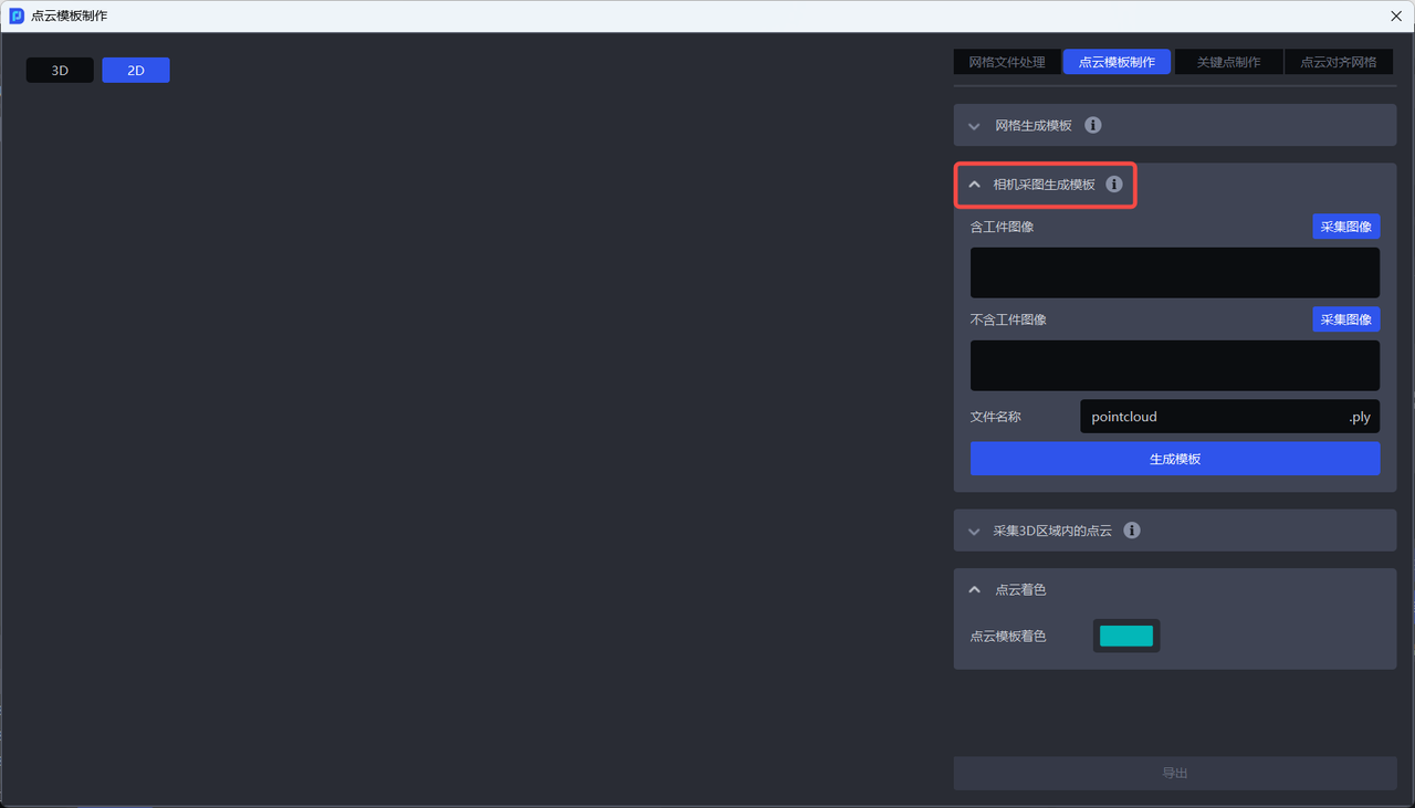
Draw a box around the target’s 2D region in the image with the target.
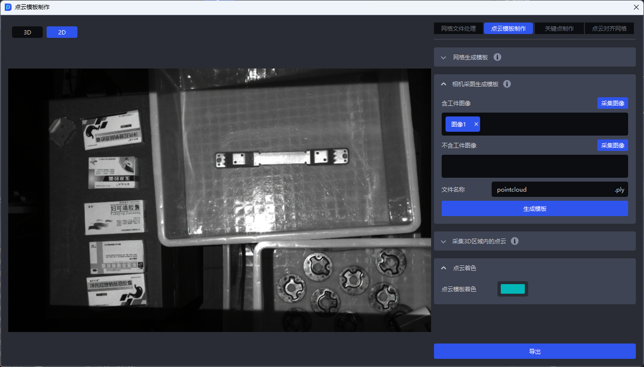
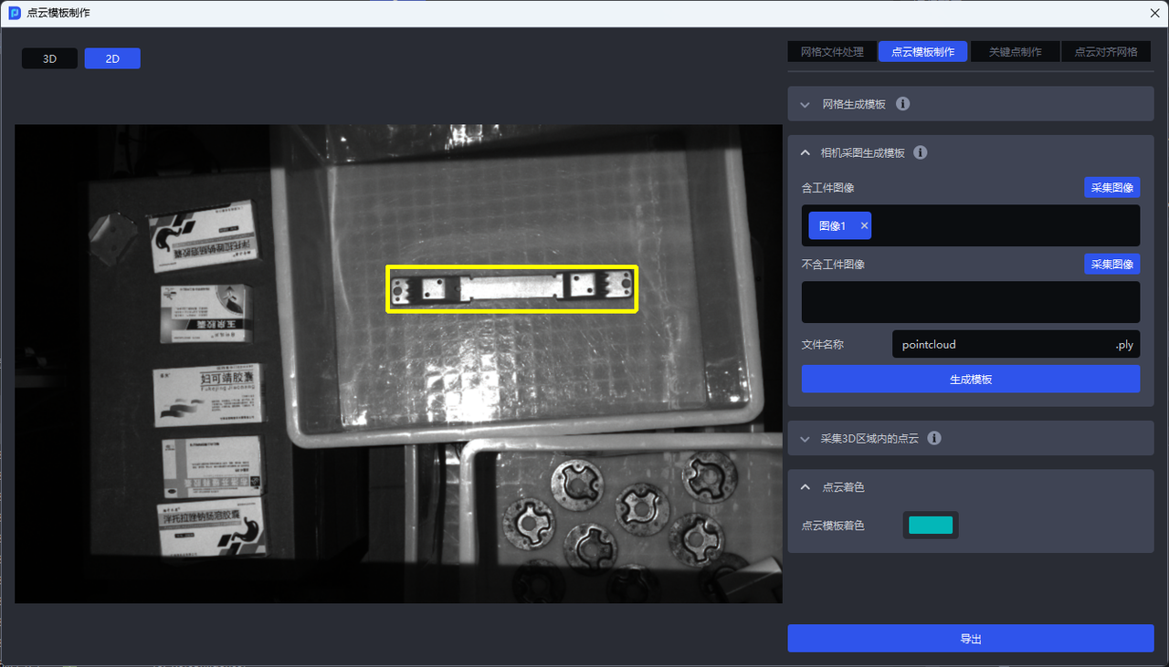
Under
Image without Target, clickCapture Imageto capture the background image. Nothing other than the target may change between the two captures.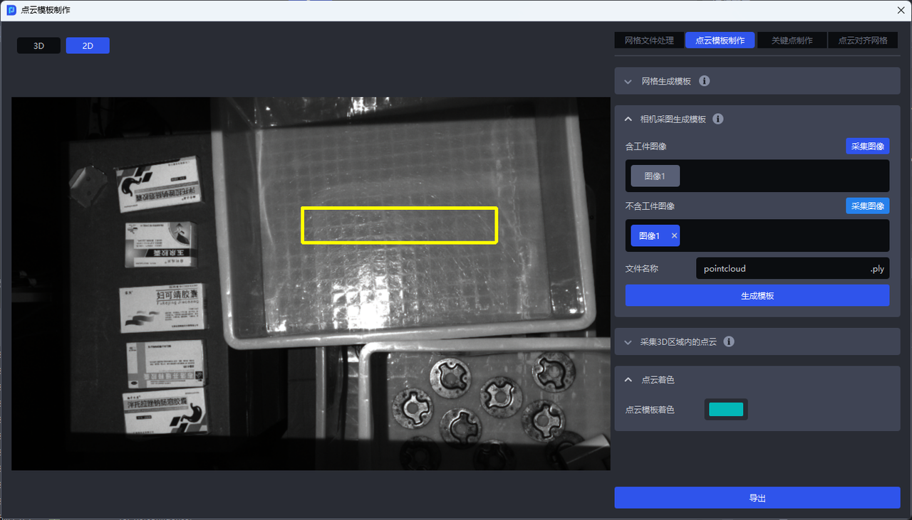
Click
Generate Template. The generated template is automatically aligned with the coordinate origin.
3.4 Capture a Point Cloud Within a 3D Region
Before starting, connect the camera and complete its configuration in the task information. For details, see the Camera Connection and Parameter Adjustment Guide.
Click
Capture Point Cloud Within 3D Region.Under
Image with Target, clickCapture Image.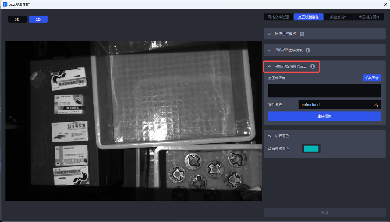
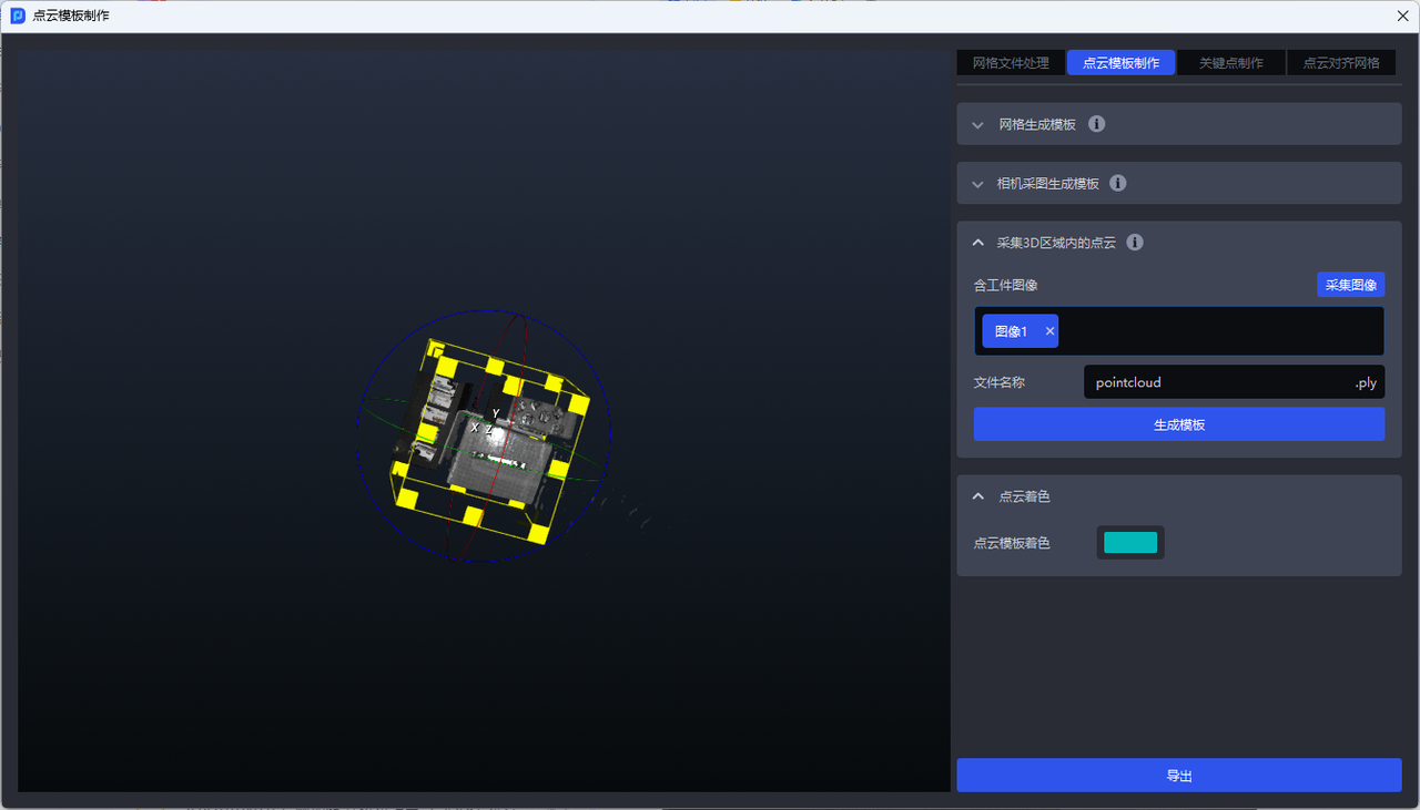
Draw a box around the target region in the point cloud image. Use the left mouse button to change the viewpoint and zoom, and the right mouse button to adjust the size and angle of the 3D box.
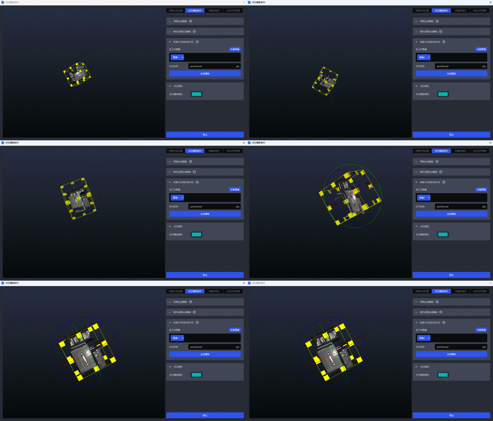
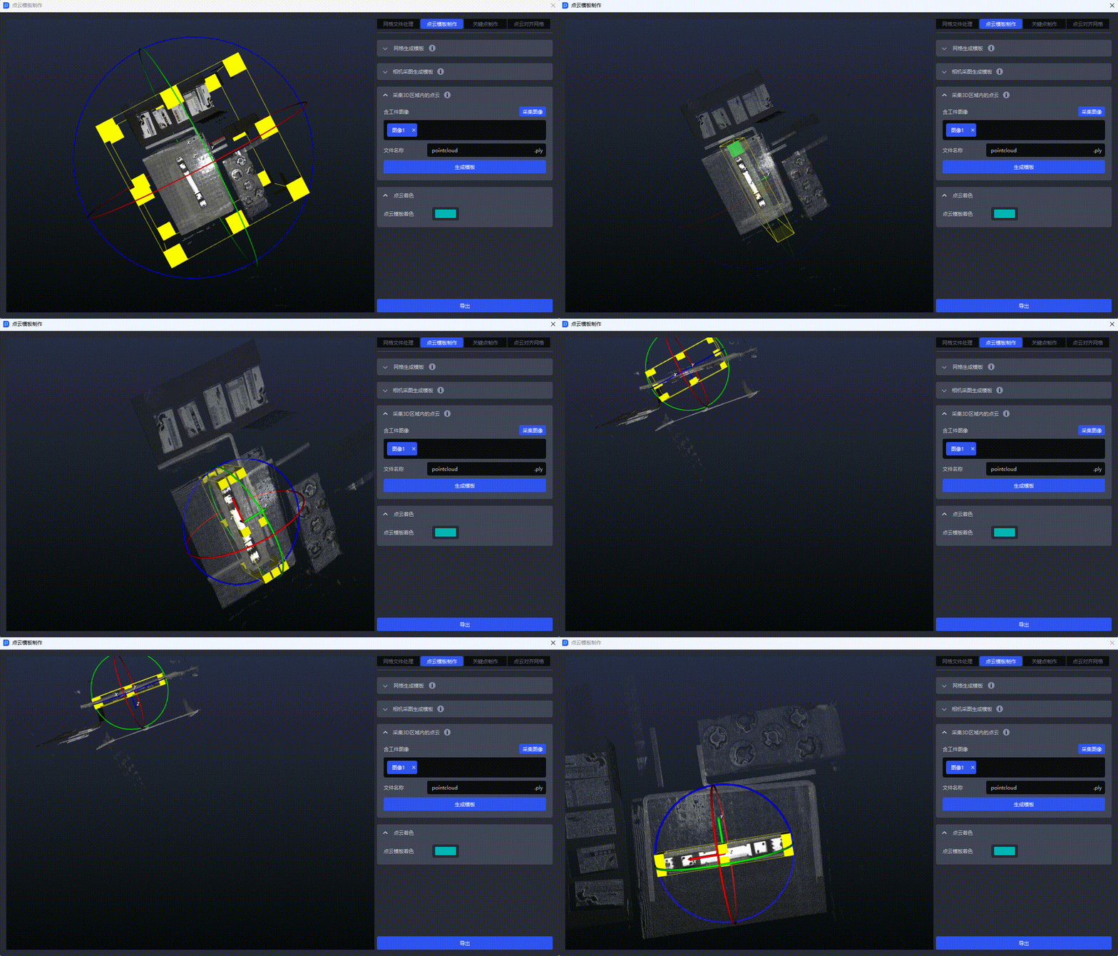
After selecting the region, click
Generate Template. The generated template is automatically aligned with the coordinate origin.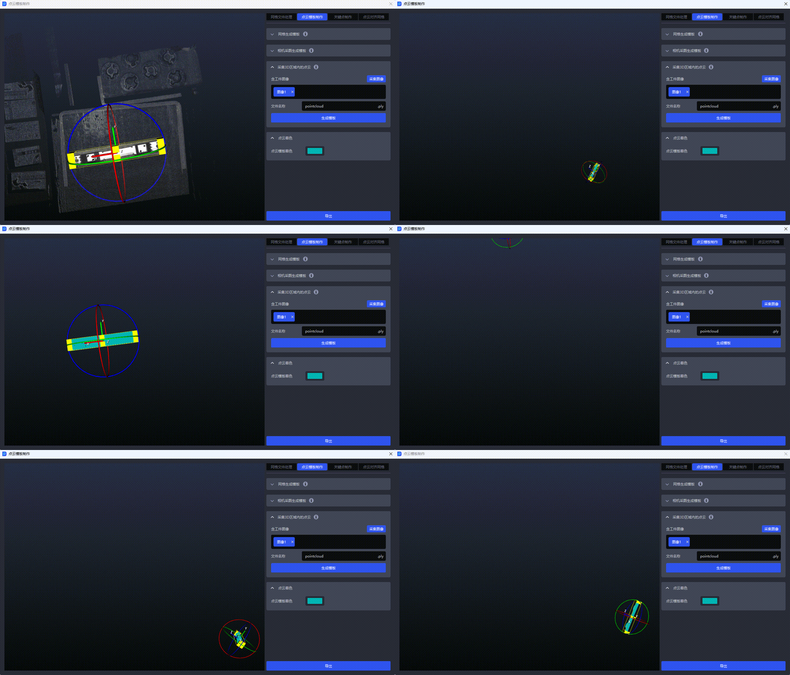
3.5 Generate a Template from Historical Data
When the project type is “Loading and unloading of neatly arranged plane type target objects (image matching)” or “Plane type Target positioned assembly (image matching only),” you can use Generate Template from Historical Data. Template source data can come from a historical data folder or an on-site capture.
3.5.1 Use Historical Data
Under
Source Data Location, select a historical data folder. Usually, select one complete data set fromdata\PickLight\历史数据\Builder\foreground\inputin the project folder.Set the path for generated template data. The default is the current project’s
datafolder, but you can choose another local folder.Select the target ROI in the left viewport, then click
Generate Target Point Cloud.Use the point cloud editing tools in the upper right to retain the required points.
Click
Generate Template Datato finish creating the template.


3.5.2 Generate from an On-Site Capture
Confirm that the camera is connected and configured in the task information.
Click
Capture Imageto generate a point cloud image, select the target ROI, and clickGenerate Target Point Cloud.Use the point cloud editing tools to retain the required points, then click
Generate Template Datato finish.


Warning
Templates generated from historical data do not support pose adjustment, alignment with the coordinate origin, downsampling, resetting, or exporting.
3.6 Edit a Point Cloud Template
3.6.1 Adjust the Point Cloud Pose
You can adjust the pose of a point cloud template. When finished, click Export at the bottom to save the template shown in the current viewport. Click Align with Coordinate Origin to move the template center to the camera coordinate system origin.
Note
- After the point cloud template center is aligned with the camera coordinate system origin,
Point Cloud to Mesh Alignmentcannot be performed again. - Templates generated from historical data do not support pose adjustment, alignment with the coordinate origin, or downsampling.
3.6.2 Color the Point Cloud
You can customize the color of the point cloud template. When finished, click Export at the bottom to save it.
3.6.3 Downsample the Point Cloud Template
Downsampling reduces the number of points and speeds up visual processing. Downsampling Point Spacing (mm) ranges from [0.0, 1000.0] and defaults to 0.0 mm. A larger value produces fewer points and faster processing, but may reduce accuracy; a smaller value has the opposite effect.
Each time you enter a point spacing, the system processes the result of the previous downsampling operation. Adjust the spacing gradually using the point count displayed at the lower left of the left viewport.
Reset
Click Reset to restore the current viewport to the template produced by the most recent click of Generate Template in this function. This also restores the downsampling point spacing to 0.0 mm and updates the point count.
4. Create Keypoints
Keypoints are 3D feature points with a defined semantic or geometric meaning. They describe a target’s local structure or overall pose. For targets that are symmetrical, have distinct front and back faces, or lack sufficient point cloud features, keypoints can assist identification.
4.1 Generate Keypoints by Downsampling
Function: Imports a standardized mesh file and generates evenly distributed keypoints across the entire target.
Suitable scene: Most general targets.
Switch to the
Create Keypointswindow and upload a standardized mesh file.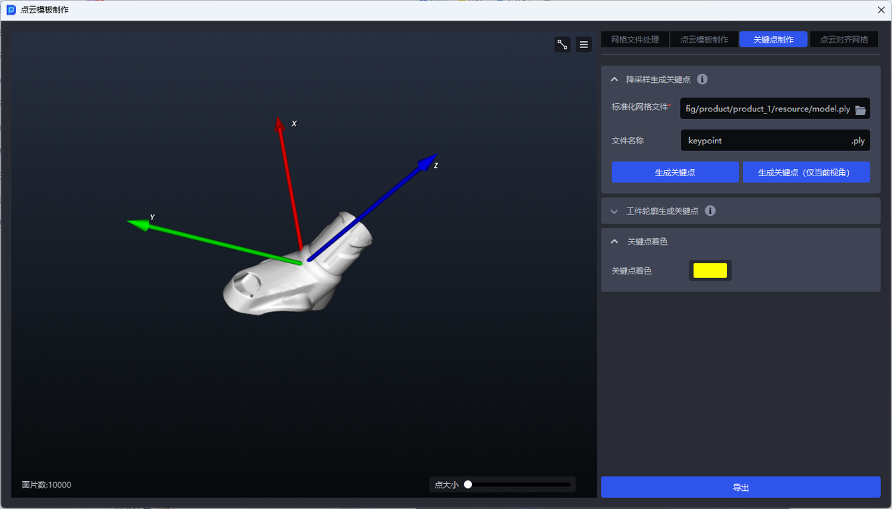
To generate all keypoints, click
Generate Keypoints.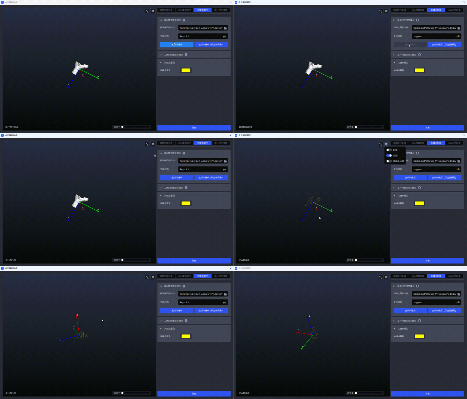
To generate keypoints only for the current viewpoint, click
Generate Keypoints (Current View Only).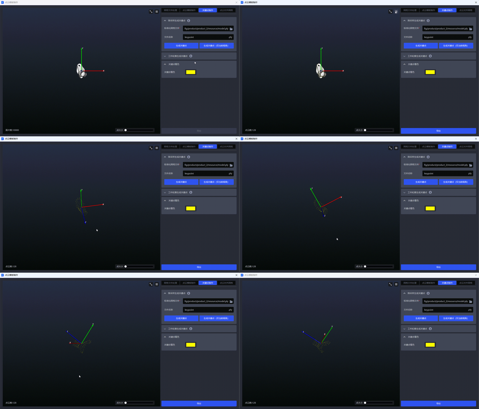
4.2 Generate Keypoints from the Target Contour
Function: Imports a standardized mesh file and generates keypoints along the target contour.
Suitable scene: Evenly distributed keypoints cannot represent the target’s features accurately, or the target has structural features such as symmetry or distinct front and back faces. Contour keypoints are usually more distinctive.
In the
Create Keypointswindow, clickGenerate Keypoints from Target Contourand upload a standardized mesh file.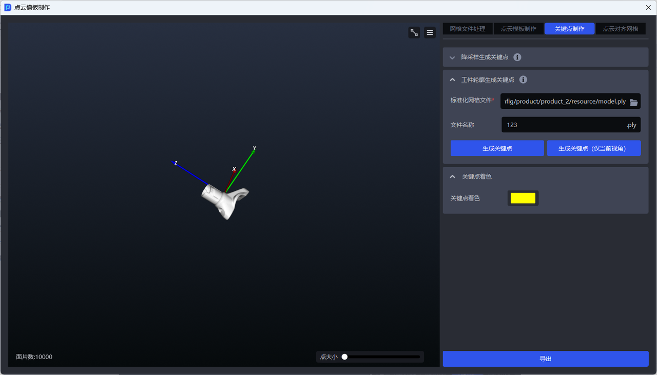
Click
Generate Keypointsto generate all keypoints.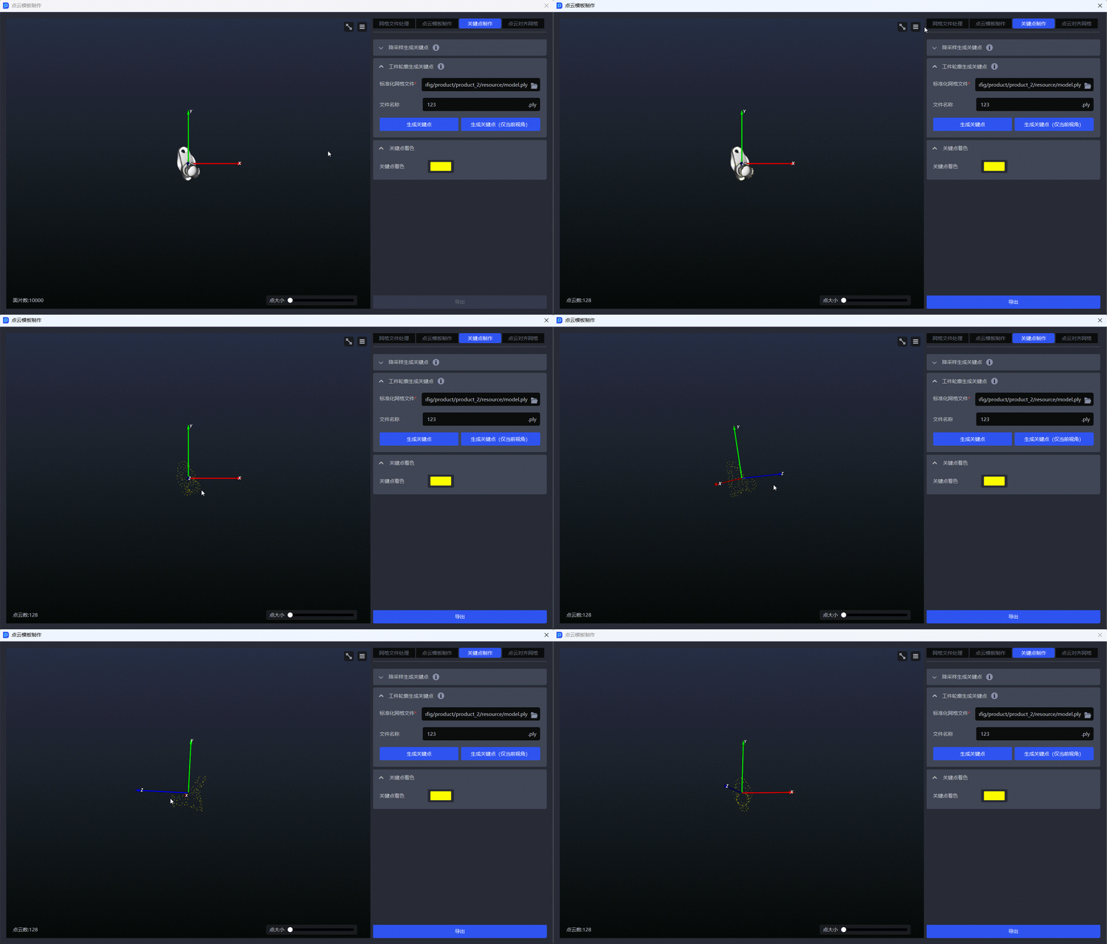
Click
Generate Keypoints (Current View Only)to generate keypoints for the current viewpoint.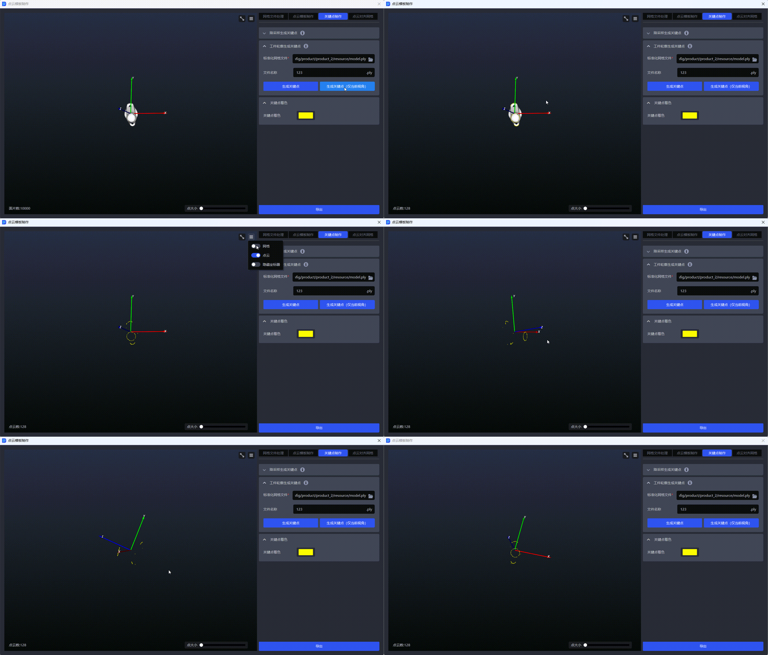
5. Align a Point Cloud with a Mesh
5.1 Function and Suitable Scene
Point Cloud to Mesh Alignment aligns the coordinate systems of a point cloud file and a standardized mesh file. It is suitable for general targets when the standardized mesh and point cloud template use different coordinate systems, especially templates generated from camera images.
A template generated from camera images uses the camera coordinate system origin by default, while the standardized mesh and keypoints generated from it use the mesh coordinate system. After alignment, the mesh, keypoints, and point cloud template share a consistent coordinate relationship for subsequent identification and matching.
5.2 Steps
Connect the camera before starting, then:
- Upload the standardized mesh file and point cloud file.
- Enter a name for the exported point cloud file.
- Click
Calculate Alignment. - Adjust the point cloud pose and color as needed, then export the result.
6. Typical Cases
The following cases can help you select a method. Images in the table are ordered “scene → point cloud → template.” For an actual project, base the selection on camera point cloud quality, target pose variation, and the matching objective.
| Case and selection recommendation | Scene image | Point cloud image | Template image |
|---|---|---|---|
| General, neatly arranged: long, planar target The target is relatively large and elongated, with a fixed placement pose. Prioritize features such as long edges, ends, and holes, and downsample planar regions as appropriate. A mesh template can use Current View Only mode. |  |   |   |
| General, randomly arranged: holes and self-occlusion Use multiview capture to identify stable regions. Use features such as the outer contour and fixed holes, and use a local template if necessary. |  |  |   |
| Plane type, neatly arranged: height differences or curved surface variations Retain depth features such as height differences, edges, and curved surface variations. Do not include invisible points on the back in the template. |  |  |   |
| Plane type, neatly arranged: height variation caused by manufacturing tolerances Select regions that remain reliably visible within the permitted variation range, and reduce reliance on a single height boundary. If necessary, add keypoints or expand the effective template region. |  |  |   |
| Plane type, randomly arranged: rotational symmetry and self-occlusion Use keypoints that represent the overall orientation and align them with the CAD center point. Select contour and depth features that remain stable across multiple viewpoints for the template. |   |  |    |
| General, randomly arranged: reflections on a convex surface and front-to-back differences Generate separate point cloud templates for the front and back faces using their current viewpoints, and generate keypoints covering the entire target. Fit the two templates to the corresponding front and back faces of the CAD model. |   |  |   |
| Plane type positioned assembly (point cloud matching only) Emphasize the contour and positioning features needed for assembly. Exclude background points and points on the back that are irrelevant to assembly. |  |  |  |
| General target positioned assembly Retain contours, holes, and height differences that constrain the assembly orientation. Use a keypoint model when point cloud features are insufficient or the structure is symmetrical. |   |  |  |
7. Checklist
Before exporting the template, check each of the following:
- The template contains only target points, with no background, fixture, or other irrelevant points.
- The template points remain reliably visible across the actual range of poses, and the features are salient and distinctive.
- The point count and density meet accuracy and speed requirements; downsampling has been completed if needed.
- The two captures used for a camera image template have consistent conditions; the historical data used for a template is complete.
- When using a mesh, keypoints, and a point cloud template, their coordinate systems are consistent; point cloud to mesh alignment has been performed for a template in camera coordinates.
- If the target is prone to wear or deformation, or shows substantial manufacturing variation, periodic review and updates have been scheduled.