
Eye-in-Hand Eye-Hand Calibration
This guide covers eye-hand calibration for three-axis, four-axis, and six-axis robots in an eye-in-hand setup. It describes two methods according to robot capability: random pose sampling and needle-tip tool point-contact calibration.
1. Shared Preparation
- Complete the Hardware Installation Guide
- Complete the Project Operation Guide and Task Operation Guide
- Complete the Camera Connection and Tuning Guide and Robot Configuration Guide
- Prepare a clean, flat, scratch-free calibration board
- Verify the robot and camera status, then open the eye-hand calibration page
Note: Needle-tip tool point-contact calibration is generally recommended first for three-axis and four-axis robots. For six-axis robots, choose random pose sampling or needle-tip calibration according to the application requirements.
2. Calibration Information Configuration (Shared)
On the eye-hand calibration page, click Add Eye-Hand Calibration. Fill in the fields as follows:
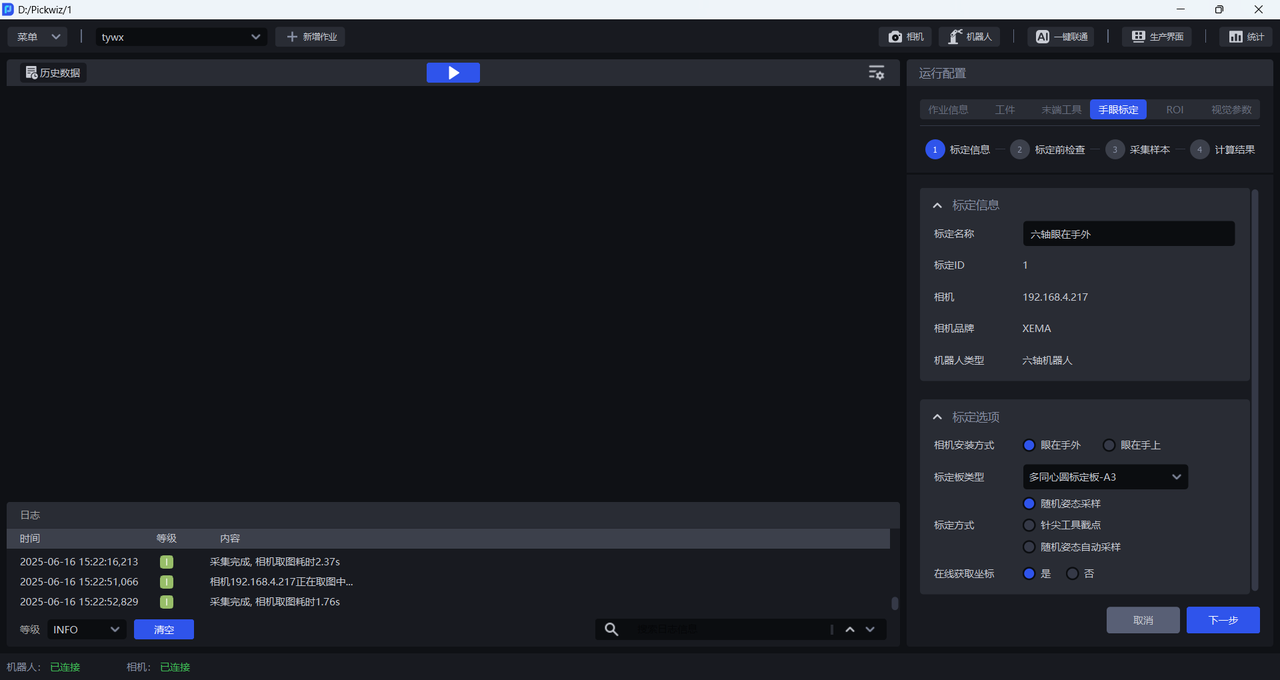
Calibration Name: Name it according to the projectCalibration ID: Used to switch calibrationsCamera: The currently connected cameraCamera Brand: The corresponding modelRobot Type: Match the robot configurationCamera Mounting Method: SelectEye in handCalibration Board Type: Select according to mounting height and robot type (see below)
| Robot Type | Camera Mounting Height | Calibration Board |
|---|---|---|
| Six-axis | Below 0.5 m | A6 multi-concentric-circle calibration board |
| Six-axis | Below 1.5 m | A5 multi-concentric-circle calibration board |
| Six-axis | 1.5–2.5 m | A4 multi-concentric-circle calibration board |
| Six-axis | Above 2.5 m | A3 multi-concentric-circle calibration board |
| Three-/four-axis | Below 0.5 m | A6 multi-concentric-circle calibration board |
| Three-/four-axis | Below 1.5 m | A5 multi-concentric-circle calibration board |
| Three-/four-axis | 1.5–2.5 m | A4 multi-concentric-circle calibration board |
| Three-/four-axis | Above 2.5 m | A3 multi-concentric-circle calibration board |
3. Pre-Calibration Checks (Shared)
- Check that the robot base is secure and has no obvious vibration
- Check that the camera bracket is secure and that its material and mounting condition are stable
- Place the calibration board on the work platform so that it covers the task area
- Check the robot’s accuracy (if it does not meet the requirements, first check Common Issues and FAQ)
4. Random Pose Sampling Calibration
4.1 Six-Axis Robot
Follow the procedure described on the Eye in hand six-axis page. Recommended settings and steps:
- Calibration Method: Select
Random Pose Sampling Calibration - Obtain Coordinates Online: Select
Yesif the robot has the corresponding calibration program; otherwise, selectNo - Control the robot carrying the camera to collect samples within the camera’s field of view
- Each time you click
Start Sampling, check whetherCamera CheckandRobot Checkpass - After the sample passes validation, click
Add Sample - Repeat the collection process and save at least 5 valid samples
- Click
Complete Collection->Calculate Results
If a duplicate or similar sample appears:
- The system displays “Similar to an existing sample”
- Delete or skip the sample, then collect another one
- Continue until the minimum number of valid samples is reached
4.2 Four-Axis Robot
If the interface supports random pose sampling for a four-axis robot, follow the same process to collect at least 5 valid samples, with collection positions covering different areas:
- Spread the samples as much as possible across the robot’s permitted directions of rotation
- Position the calibration board to cover the four corners of the field of view as much as possible
For three-axis robots, use needle-tip tool point-contact calibration.
4.3 Result Handling
After clicking Calculate Results, open Calibration Result Inspection and Analysis:
- If the error is abnormal, use the error chart and scene view to identify problematic samples
- If necessary, return to the sampling page to collect additional high-quality samples
5. Needle-Tip Tool Point-Contact Calibration
5.1 Six-Axis Robot
- Calibration Method: Select
Needle-Tip Tool Point-Contact Calibration - Prepare the needle-tip device and confirm that the tip is within the camera’s field of view
- Complete the calibration information configuration and preliminary checks, then start sampling
- After clicking
Start Samplingto enter point collection mode, touch the target circle centers in the order shown by the interface - After each contact point is captured, click
Add Sample - Collect no fewer than 3–6 concentric-circle contact points, then click Next
- Proceed to result calculation, complete the error check, and apply the result
Optional: Some projects add sampling positions within the same process. Use
Add Positionto sample at multiple positions to improve robustness in complex scenes.
5.2 Three-Axis and Four-Axis Robots
Follow the same process as for a six-axis robot. When collecting points more densely, prioritize touching multiple circle centers within the concentric circles to reduce the risk of geometric degeneracy.
The needle-tip tool point-contact method is recommended first for three-axis and four-axis robots. If site constraints prevent needle-tip contact, use random pose sampling and increase sample coverage.
5.3 Result Assessment
For every robot type, return to Calibration Result Inspection and Analysis to confirm:
- Whether the pose distribution in the scene view is sufficiently spread out
- Whether the error chart meets the requirements
- Whether point cloud reprojection is stable
6. Select the Eye-Hand Calibration Configuration
After calibration, select this configuration from the Run Configuration -> Task Information -> Eye-Hand Calibration dropdown and apply it.
If the result is abnormal after a reset, repeat the process in Section 4 or 5 of this page.
7. Common Issues and Related Pages
If you get stuck at a sampling step, first see: