
Create a Task and Set Up Basic Configuration
3. Create a Task and Set Up Basic Configuration
3.1 Create a Point Cloud Matching Only Task
When setting up the project for the first time:
- In PickWiz, open New Empty Project.
- Select Positioned Assembly > Plane type Target positioned assembly (only Point Cloud matches).
- Set the project name and storage path. You can use
ingot01as the name; it must not contain Chinese characters or spaces. - Do not add optional features yet. Verify the default workflow first.
- Click Create and confirm that the generated task type is correct.
For an existing project, use New Task to select the same scenario. You can use a general task name such as “Aluminum Ingot Marking.” The task type cannot be changed directly after creation.
For complete instructions, see Create an Empty Project and the Task Operation Guide.
3.2 Associate the Camera and Robot
- Select a connected camera configuration and capture a point cloud of the current aluminum ingot.
- Check the outline, depth continuity, and missing regions of the features used for positioning. Adjust imaging before creating a template.
- Select the corresponding robot configuration and verify the communication method, connection role, and coordinate conventions.
- Verify capture and communication first. Do not let the robot move using positioning results that have not yet been validated.
For camera and robot configuration, see the Camera Connection and Parameter Tuning Guide and the Robot Configuration Guide, respectively.
3.2.1 Establish a Comparable Camera Imaging Baseline
This example uses a XEMA structured-light camera. Adjust the raw point cloud imaging before creating a template. For other camera models, use the corresponding camera guide; do not apply the parameter names or values below directly.
- Select a camera configuration template suited to the aluminum ingot’s surface characteristics, then use the + on the right to add an editable configuration. Default templates cannot be modified directly.
- Keep the camera, aluminum ingot, and lighting fixed. Use a positioning feature near the marking area as the observation target. Enable Lock View to make successive captures easier to compare.
- Trigger a capture and inspect the 2D image, depth image, and point cloud separately. Enable Show Overexposed Areas to help assess the result, but do not judge point cloud quality from the brightness of the 2D image alone.
- Save the current configuration and data from the same capture as a baseline. During offline debugging, first reduce the effect of filtering on point cloud density so you can inspect the original missing regions and noise. Do not disable filtering directly during automatic operation.
3.2.2 Adjust the Engine, Exposure, and Projection Brightness
- Compare available engines, such as standard and high-reflectivity engines, against the actual surface. Focus on whether positioning edges, groove bottoms, and steps are preserved, rather than whether the background appears brighter.
- Start with Single Exposure. Adjust only the exposure time on each attempt, trigger a capture, and record missing data, overexposure, noise, and capture time in key regions.
- If dark areas show substantial missing data after shortening the exposure, increase it gradually. If bright-area details disappear after increasing the exposure, reduce it and recheck the depth image and point cloud. Do not assume that “brighter” means “better.”
- If the point cloud remains stable and complete across a range of exposure times, choose a shorter exposure verified through repeated captures to reduce capture time.
- If there is still substantial overexposure at the shortest usable exposure, evaluate a lower Projection Brightness. Record exposure time and projection brightness together.
- If different exposures each preserve different regions, switch to High Dynamic Range and combine those effective exposures. Check whether the fused result preserves all required features, and minimize unnecessary exposure groups.
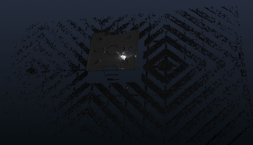
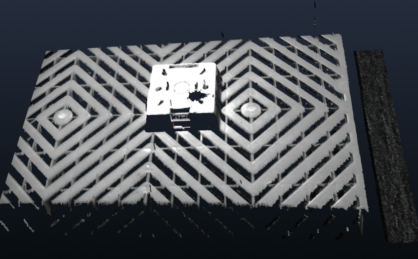
The following are exposure examples for a general target from the original reference material. They are not measurements of an aluminum ingot or a set of “incorrect versus correct” acceptance images. The short-exposure image has fewer point cloud points in dark areas and the background. The long-exposure image has greater coverage, but details in bright areas of the target are also weaker. Assess the geometry used for positioning rather than comparing overall brightness alone.
3.2.3 Recheck Positioning Features After Noise Reduction
- Once point cloud coverage meets the requirements, add smoothing, confidence filtering, or applicable noise filtering one at a time. Recapture the same scene after each adjustment.
- Zoom in on positioning edges and groove bottoms. Check whether stray points have decreased, and confirm that real steps, thin edges, and small features have not been filtered out. Camera confidence here is different from Visual Model recognition confidence.
- Do not use increased gain as a substitute for exposure tuning. Check point cloud noise whenever gain is increased.
- Adjust 2D Image Overlay Exposure only if 3D imaging is satisfactory but the 2D display is still unsatisfactory. This feature cannot restore missing point cloud data, and this task does not rely on 2D instance recognition.
- Repeat captures at a normal position, at the maximum permitted tilt, and with a more reflective surface. Record feature completeness, noise, capture time, and the stability of subsequent matching.
- Save the camera configuration and verify its selection again in the current task before creating a template. If you later change imaging parameters, retest the original template and positioning results.
For parameter ranges and interface descriptions, see the Camera Connection and Parameter Tuning Guide.
3.3 Define the Capture Pose and Tool Frame
- Place the aluminum ingot at a representative incoming position so that the selected features are fully within the field of view.
- Adjust the camera pose and distance so key features are imaged consistently, minimizing missing points caused by occlusion and reflections.
- If the camera is mounted on the robot end, save the capture position on the robot. For a fixed camera, record the installation and incoming-material references.
- Recheck using the permitted changes in position and angle. Do not cover only the pose used to create the template.
- Add or select the actual end-effector configuration and confirm its TCP definition.
- If using a tool model, verify how its dimensions, origin, and orientation relate to the actual TCP.
Capture Pose and Positioning Results
When the camera moves with the robot, the image and Robot Pose must correspond to the same capture. Do not pair a Robot Pose from another capture position with the current point cloud, or use results from a previous scene directly to control the current target.
For tool models and coordinate settings, see the End-effector Configuration Guide.
3.4 Select and Verify Eye-hand Calibration
- Select the calibration workflow based on whether the installation is eye in hand or eye to hand, and on the number of robot axes.
- Before calibration, verify the robot’s pose representation and camera imaging quality.
- After calibration, check the results and record the actual positioning error.
- Select the corresponding calibration configuration in Task Information and confirm that the installation has not changed.
For the calibration workflow and checking methods, see the Eye-hand Calibration Procedure and Check and Analyze Calibration Results.
3.5 Configure a Single-Target ROI
3.5.1 Load the Current Scene
- Add an ROI and save the configuration under a general name.
- Use Capture Image to acquire data on site, or import historical images and point clouds from the same capture.
- Confirm that the display shows the current target rather than a scene left over from the previous ROI setup.
- If the historical data lacks a PLY point cloud, generate the point cloud in the historical data before importing it.
3.5.2 Limit the Spatial Area Used for Matching
- Adjust the ROI 3D orientation using the aluminum ingot’s positioning feature surface as a reference. Typically, the positive Z direction should point outward, perpendicular to the feature surface.
- Include all features required by the template and the permitted variation in incoming positions.
- Exclude adjacent aluminum ingots, supports, conveyors, and other repeated structures so that the same region does not contain multiple matchable candidate targets.
- Check the boundaries from front, side, and oblique views. Do not crop out steps or edges used to distinguish orientation.
- Save the ROI and select it in Task Information.
If ROI 2D must be configured, it should cover the corresponding observation area. Do not try to solve this example’s point cloud matching issues by adjusting 2D recognition parameters. For instructions, see the ROI Configuration Guide.
3.5.3 Check the Allowed Region for the Positioning Point
The features used for matching may be beside the marking area. When configuring ROI-type filtering later, confirm that the actual positioning point falls within the selected allowed region. Do not judge this solely by the size of the template region.
Do not expand the matching workspace to an adjacent aluminum ingot just to retain a positioning point filtered out by mistake. First distinguish the matching area from the area in which output points are allowed, then configure the corresponding regions and filtering conditions.
3.6 Save the Basic Configuration
Confirm that the camera, robot, end-effector, calibration, and ROI all refer to the current task. Keep the new task’s default vision parameters. After configuring the template and positioning point in the next chapter, perform the first vision run.
Back to Case Overview · Previous Chapter: Scenario Description and Pre-configuration Checks · Next Chapter: Point Cloud Template and Marking Positioning Point Configuration