
Operation and Acceptance
6. Operation and Acceptance
Acceptance is divided into four stages: historical data, live capture, positioning without marking, and actual marking. Proceed to the next stage only after the previous stage passes.
6.1 Validate with Historical Data
- In Vision Calculation Configuration, switch the input to Historical Data.
- During debugging, select Save All (Debug Mode) and save the configuration.
- Select complete samples and check the current target, template, positioning point, ROI, and vision parameters.
- Run the task and review the logs for this run’s timestamp.
- Keep the results from before and after parameter changes, and compare them using the same input.
If no suitable historical samples are available, first capture a normal scene while the device is prevented from performing any marking action. For instructions, see the Historical Data Feature User Guide and the Vision Calculation Configuration Feature User Guide.
6.2 Inspect Template Matching and the Positioning Point
6.2.1 Inspect the Correct Structure
- Display the Target Template in the 3D visualization.
- Inspect the alignment between the template and the actual aluminum ingot from multiple angles.
- Compare edges, steps, and grooves in particular to rule out a match to a similar plane or another repeated structure.
- Check whether the template orientation and surface normal are as expected.
- Compare repeated captures for slipping, flipping, or sudden changes.
For this task, “one instance is output” does not prove that the identified position is correct. You must also confirm that the template fits the specified structure.
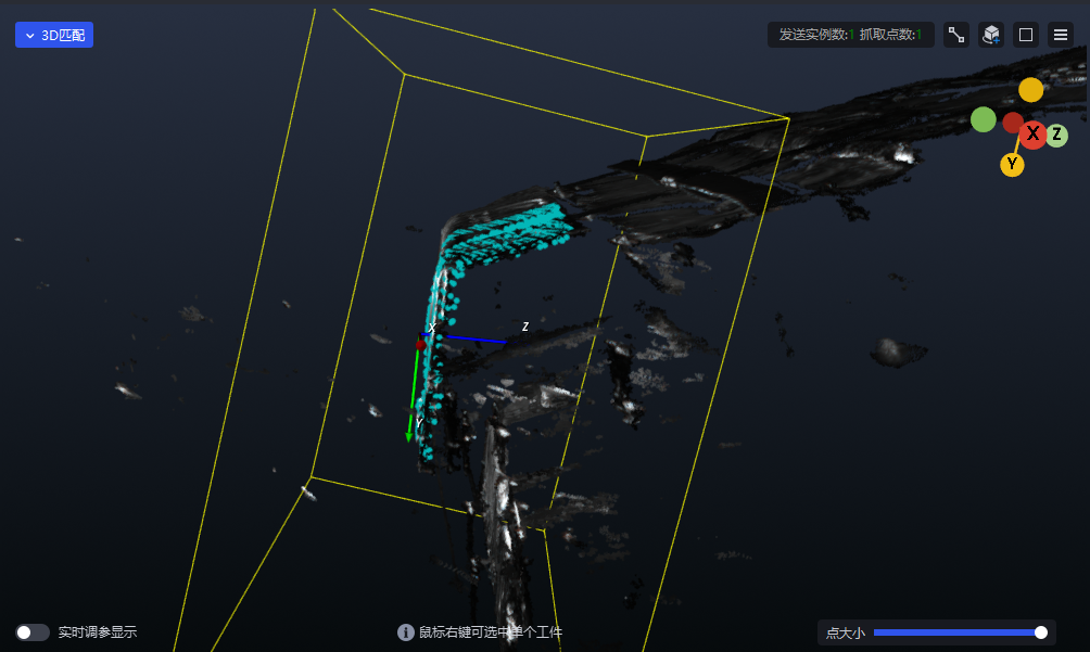
Check whether the cyan template in the image fits the scene edges, then rotate the view to the side to inspect the depth direction. This image illustrates how to review the result. A single overlay image cannot establish final positioning accuracy or replace the subsequent positioning and marking acceptance tests.
6.2.2 Inspect the Marking Pose
- Whether the positioning point falls within the specified marking area or at the agreed tool reference position.
- Whether the tool orientation matches the actual TCP and approach direction.
- Whether the positioning point moves correctly with the aluminum ingot when it shifts or tilts.
- Whether the working distance or fixed offset has been applied more than once.
- Whether valid results are incorrectly filtered out, and whether matches to the wrong area, at the wrong angle, or of low quality are excluded.
6.3 Check Logs and Live Capture
| Observation stage | Key checks |
|---|---|
| Point Cloud input and preprocessing | Whether complete features are retained, whether background remains, and whether the number of points after sampling is reasonable |
| Coarse Matching | Whether the initial position and orientation are correct, and whether there are processing time or sampling notices |
| Fine matching | Whether the template fits, and the error and processing time before and after refinement |
| Empty check and positioning point processing | No-material response, reasons for filtering, and final number of outputs |
| Device interaction | Whether this run’s result is valid and whether the coordinate conventions used are consistent |
For an explanation of the logs, see Log Description.
After the historical samples pass validation, switch the input back to Camera Data and capture at the actual image acquisition position. Cover the permitted shifts and tilts of incoming ingots, surface conditions, and no-material conditions. If the results differ significantly from the historical data, first check whether imaging, installation, or target conditions have changed.
6.4 Validate Positioning Without Marking
Disable the marking trigger first
When linking the systems for the first time, prevent any actual marking action and validate only device positioning. After confirming that the coordinate system, units, TCP, calibration results, and current captured data are all correct, perform low-speed, single-step tests in accordance with the site’s safety procedures.
- Confirm that the device uses the result from the current camera capture, rather than historical data or an expired cache.
- If the camera moves with the robot, confirm that the capture pose corresponds to the image.
- Approach the target from a safe position, maintaining a safe distance suitable for inspection.
- Check position and orientation errors using a measurement method permitted by the process.
- Validate the approach and withdrawal paths and clearance from adjacent equipment and structures.
- Test device behavior separately at the incoming-material limits, with tilted material, and with no target present.
For calibration and coordinate issues, see Checking and Analyzing Calibration Results and the Robot Configuration Guide.
6.5 Validate Actual Marking
After positioning without marking meets the requirements, enable the process action in accordance with the operating procedures for the actual marking device:
- Confirm that process personnel have approved the tool working distance, approach direction, and execution parameters.
- Perform a single marking operation on an approved test piece using nonsensitive sample content.
- Check the mark’s position, orientation, and actual quality, distinguishing vision positioning errors from tool or process issues.
- Extend testing to the permitted variations in incoming material and confirm that the mark always remains within the specified area.
- Verify that positioning failure, no material, communication faults, and manual intervention do not cause unintended marking or reuse of old coordinates.
This case does not replace the process parameters or safety requirements of a specific marking device, and it does not assume laser, contact, or any other marking method.
6.6 Acceptance Records
| Test condition | Pass criteria |
|---|---|
| Normal incoming material | The template is on the correct structure, and the positioning error and mark position meet requirements |
| Maximum permitted shift and tilt | Positioning still succeeds, the orientation does not jump, and the result remains within the permitted area |
| Surface and reflectivity differences | Usable features remain available; unreliable results are prevented from being executed |
| Interference from repeated structures | Positioning does not target another similar area or an adjacent aluminum ingot |
| No material and missing features | Marking is not performed when there is no valid result, and the status response is correct |
| Continuous operation | Positioning, marking quality, cycle time, and recovery from faults remain stable |
Record generic sample IDs, the configuration version, position and angle errors, actual marking results, processing time, and responses to faults. The number of tests, error limits, and cycle time limits are determined by the site’s process requirements. Material shown externally must not contain customer identifiers or real business codes.
Return to Case Overview · Previous Chapter: Vision Parameter Configuration · Next Chapter: Common Requirements and Troubleshooting