
Point Cloud Template and Marking Positioning Point Configuration
4. Point Cloud Template and Marking Positioning Point Configuration
This chapter establishes the fixed relationship among the positioning features, template coordinates, and marking positioning point. This case uses registration against the actual point cloud; it does not follow the Visual Model training and custom key point workflow used in the pneumatic cylinder general target case.
4.1 Select Distinctive Geometric Features
- Prioritize rigid, stable structures near the marking area whose relationship to the target position remains consistent.
- Consider how the features constrain both position and orientation, rather than focusing only on whether the point cloud is flat.
- Check whether the structure appears elsewhere on the aluminum ingot and whether adjacent ingots could produce similar point clouds.
- Recheck visibility across the permitted incoming angles and positions, avoiding areas frequently obscured or disrupted by strong reflections.
| Candidate area | Main risk | Recommendation |
|---|---|---|
| Large plane without boundaries | Sliding within the plane or uncertain orientation | Include distinguishable structures such as stable edges or steps |
| Grooves or protrusions repeated in multiple places | Positioning at a similar location | Use a combination of structures that distinguishes the location, and tighten the single-target ROI |
| Reflective surface prone to missing data | Point Cloud fluctuations make the pose unstable | Improve acquisition first, then select an area that remains reliably visible |
| Part whose relationship to the marking position can change | The template matches correctly, but the marking position is still offset | Choose a stable reference or configure each model separately |
4.2 Capture and Edit the Template
- Move the Camera to the established image capture position and confirm that the aluminum ingot and Camera are stable.
- Open Point Cloud Template Creation and select Capture Point Cloud in 3D Region.
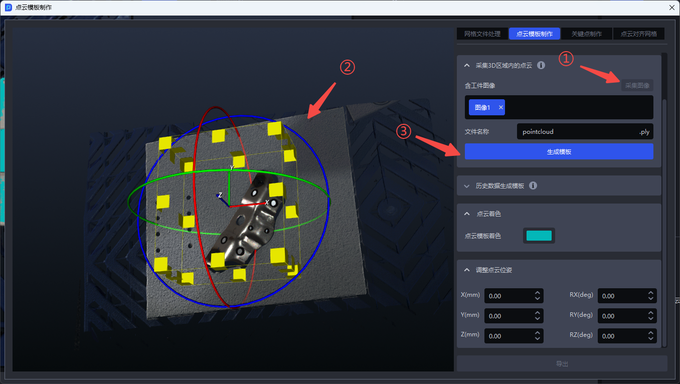
- Click Capture Image, then draw a box around the required features in the 3D window.
- Inspect the selected region from multiple viewpoints to ensure it does not include the background, supports, or adjacent aluminum ingots.
- Click Generate Template and inspect the resulting Point Cloud.
- Use the Point Cloud editing tools to remove clear noise and irrelevant points while retaining details needed to determine orientation.
- Keep an original template without downsampling, then assess downsampling based on matching performance and processing time.
Do not treat a point cloud with few remaining points and a smooth shape as the standard for template quality. Effective geometric constraints matter more than simply reducing the point count. For detailed instructions, see the Point Cloud Template Creation Guide.
The following image is a general target example from the original reference material: ① capture an image, ② adjust the 3D box to retain the required features, and ③ generate the template. It illustrates where to access the function and how to select a region; it does not show the actual extent of the aluminum ingot template.
4.3 Check the Template Coordinate Frame and Orientation
- Examine how the template coordinate axes relate to the feature surfaces, and record the reference used by the positioning point later.
- For the acquisition method used in this case, keep the template’s positive Z direction approximately aligned with the Camera’s line of sight to avoid an excessively large difference in initial orientation.
- Check for unintended flips or scale changes during adjustment.
- Export the final template before configuring the positioning point.
- After replacing the template or readjusting its coordinate frame, recheck the positioning point and orientation constraints.
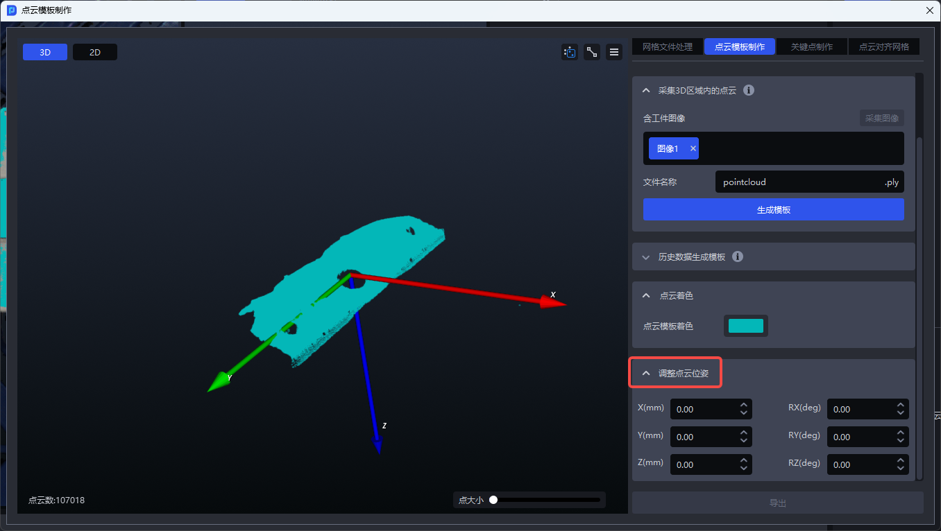
The image shows where to adjust the pose and displays the template coordinate axes. Check the axis directions against the actual features in this case; do not copy the example values. Rotating the view changes only the viewing angle, not the template coordinates.
Distinguish the Three Sets of Axes
The template Z axis, ROI Z axis, and tool TCP Z axis serve different purposes; their values or directions do not need to match. The template is used for matching, the ROI defines the region and angular reference, and the tool axis is defined by the actual TCP and process. Do not arbitrarily flip any coordinate frame merely to “align the directions.”
4.4 Configure the Template for the Target
- Add the corresponding target on the Target page, using a general name such as “Aluminum Ingot.”
- Import the final template into Point Cloud File.
- In the visualization window, confirm that the loaded template, dimensions, and coordinate orientation are correct.
- Check that the current target matches the actual incoming model and marking area.
- Save the target and select this configuration in Task Information.
This workflow does not require training a 2D recognition model for the target or importing the keypoint_128.ply file used by the general key point model. For descriptions of the software fields, see the Target Configuration Guide.
4.5 Set the Marking Positioning Point
4.5.1 Define the Position and Tool Orientation
In the target configuration, use the Pick Point field to set the marking positioning pose for this case:
- Expand the Pick Point settings. If no positioning point exists yet, add one before opening it for editing.
- Identify a reference position on the template that corresponds to the actual marking area.
- Adjust the position and orientation using the selected coordinate mode while observing the visualization on the left.
- Check the tool approach direction, TCP definition, and process working distance, and confirm where the required offset is applied.
- Save the edited result, return to Task Information, and confirm that the current Task uses this target.
The relative coordinate mode is generally better suited to fine adjustments along the current positioning point’s direction. Before copying values, confirm that both configurations use the same reference coordinate frame. Do not copy only the numbers while overlooking differences between reference frames.
4.5.2 Avoid Applying Offsets Twice
The marking positioning point, Pick Point adjustment function, and equipment execution program can all introduce pose offsets. Define the source of each offset clearly:
| Offset source | Information to record |
|---|---|
| Target positioning point | Fixed position and orientation relative to the template |
| Vision runtime adjustment | Reference frame used, adjustment order, and purpose |
| Equipment execution program | Process definitions such as tool working distance and approach and retreat positions |
Configure the same working distance or fixed offset only once, as agreed. If the vision result is incorrect, do not use compensation on the equipment side to temporarily conceal a template or calibration problem.
If runtime adjustment is needed, see the Pick Point Adjustment Function Configuration Guide.
4.6 Check the Relationship Between the Template and Positioning Point
- The positioning features remain reliably visible across the permitted range of incoming material and cannot be confused with nearby repeated structures.
- The template contains no irrelevant Point Cloud data, and its dimensions and axis directions are correct.
- The positioning point’s relationship to the template matches the actual marking position.
- The tool orientation and offsets are clearly defined, with no duplicate compensation.
- The template, positioning point, and current target configuration have been saved and are ready for validation with fixed samples.
Return to Case Overview · Previous Chapter: Create a Task and Configure Basic Settings · Next Chapter: Vision Parameter Configuration