Point Cloud Template Creation Guide
Mesh files, keypoints, and Point Cloud Templates are all used for 3D Matching. Generic workpieces must upload mesh files, Point Cloud Templates, and keypoint files. Surface-type workpieces must upload mesh files and Point Cloud Templates. Circular-surface workpieces, cylindrical workpieces, and quadrilateral workpieces may need to upload Point Cloud Templates.
The Point Cloud Template creation function in PickWiz includes four parts: mesh file processing, Point Cloud Template creation, keypoint creation, and aligning Point Cloud to mesh. The operation method is as follows.
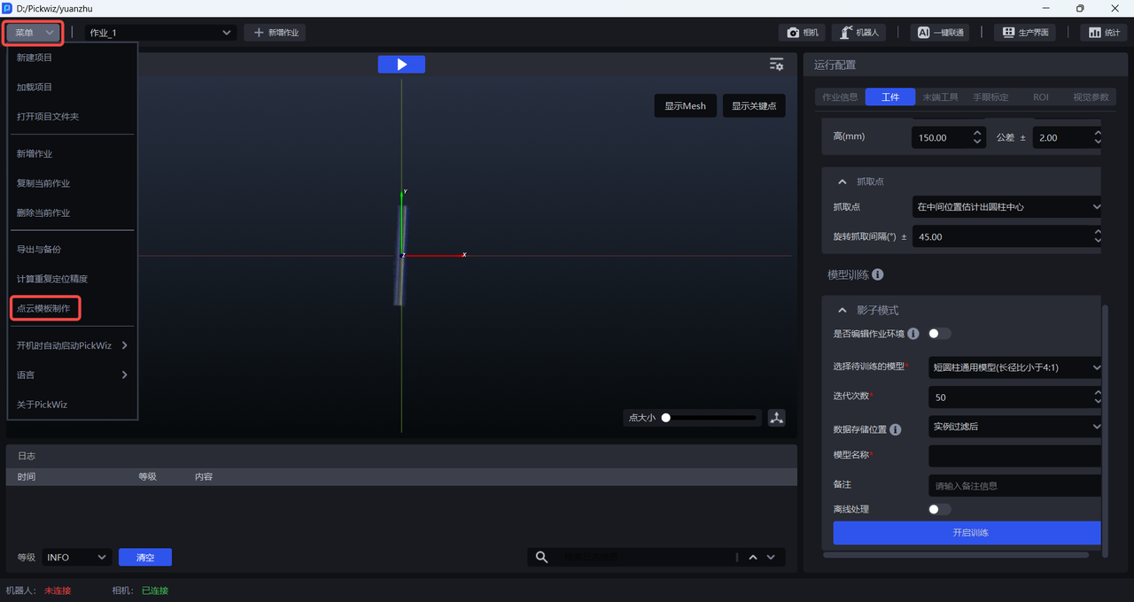
On the main interface, click Menu>Point Cloud Template Creation to open the Point Cloud Template Creation window, as shown below.
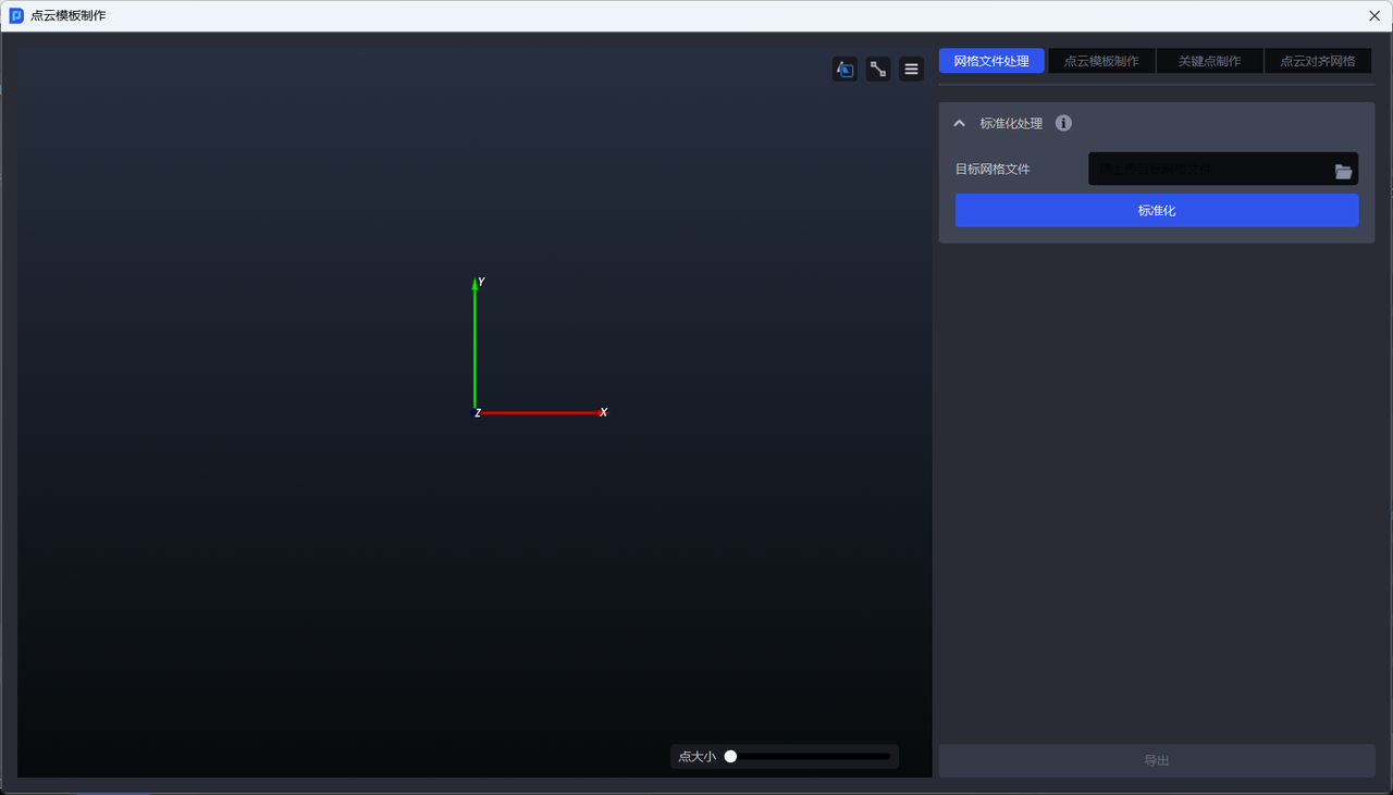
1. Mesh file processing
A mesh file is a file that stores 3D model data, generally the CAD model of the workpiece, and is used for One-Click Integration vision model training. CAD models mainly come from user-provided models or internal scanning by the company.
If the generic vision model cannot recognize the workpiece,
One-Click Integrationtraining is required. The mesh file must undergo standardization processing to ensure the final training effect of the vision model.
Standardize mesh file
Feature Description
Complete mesh file standardization with one click, including aligning the coordinate axes to the center of the mesh model, increasing or reducing the number of faces of the mesh model, and unifying the unit to m.
Applicable Scenarios
One-Click Integrationtraining: The mesh file must undergo standardization processing before it can be normally used forOne-Click Integrationmodel training.Generating a Point Cloud Template from a mesh file: The mesh file must undergo standardization processing before a Point Cloud Template can be normally generated.
Aligning Point Cloud to mesh: The mesh file must undergo standardization processing before alignment can be performed normally.
Note
For the same mesh file, standardization only needs to be performed once. Repeated standardization will cause “side effects.”
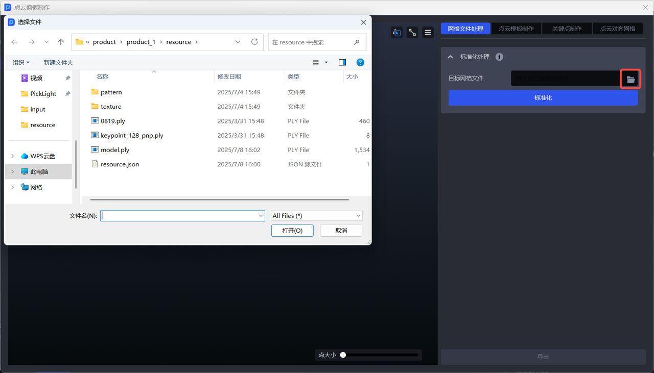
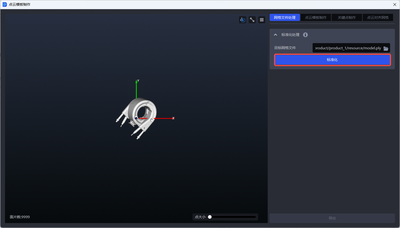
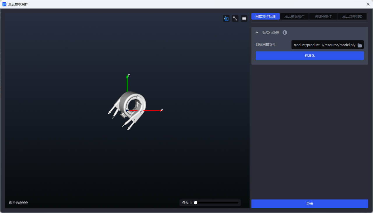
- Upload the CAD model of the workpiece, as shown below.
- After clicking
Standardize, theExportbutton becomes clickable, as shown below.
For the same mesh file, standardization only needs to be performed once
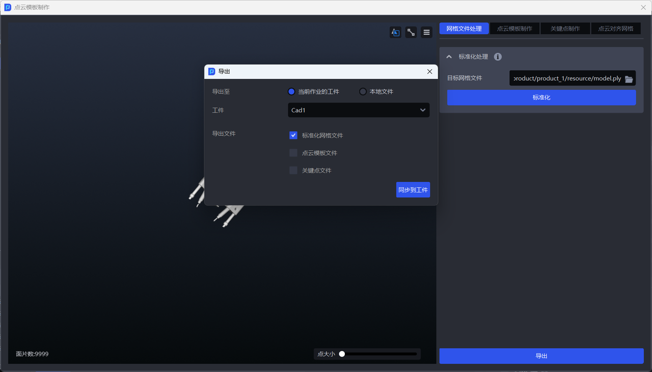
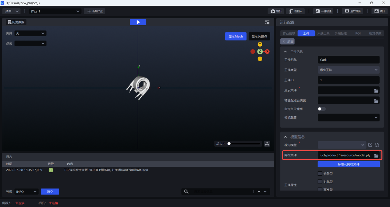
- Select
Current Task Workpieceand clickSync to Workpieceto automatically upload the standardized mesh file to the workpiece, as shown below.
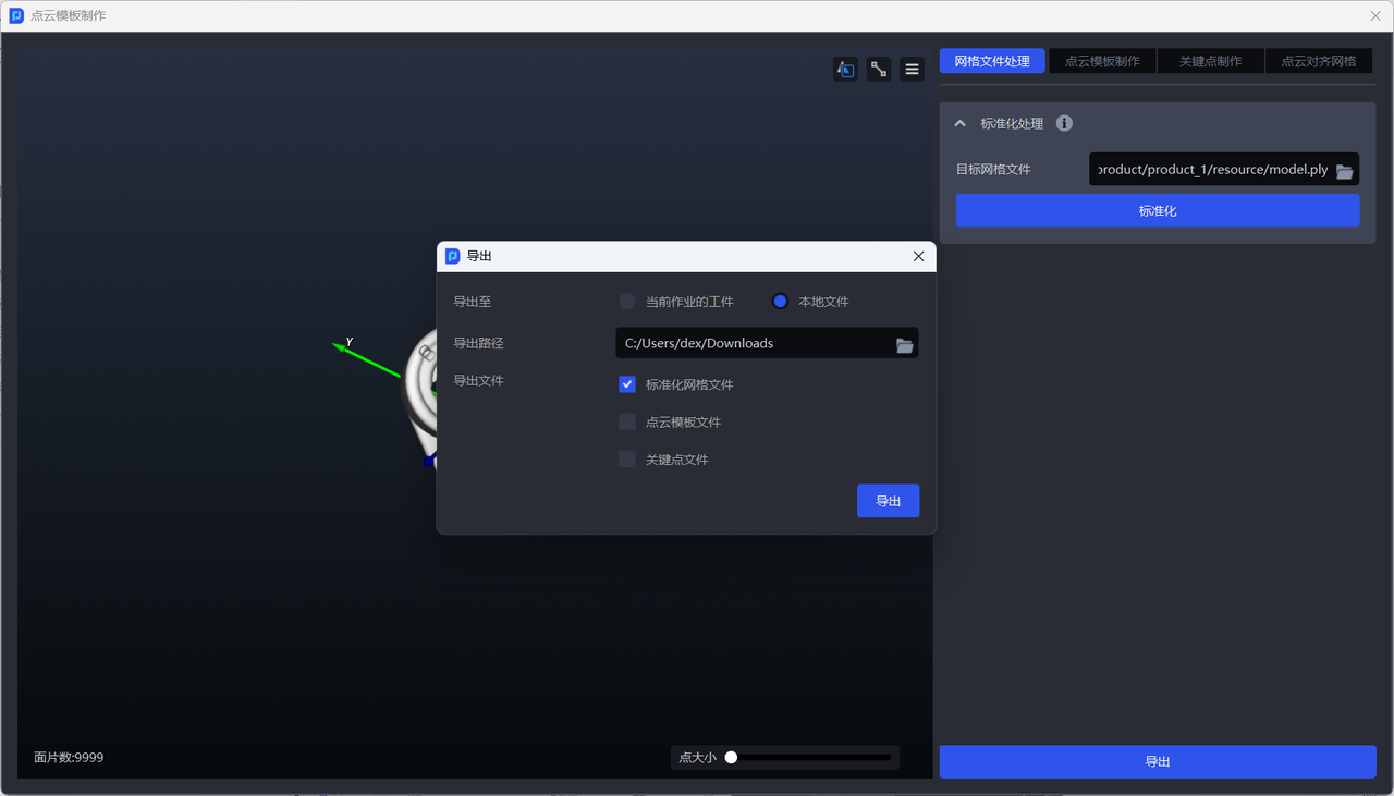
- If you need to create a Point Cloud Template or align a Point Cloud Template to the mesh, export the standardized mesh file to the local computer.
2. Point Cloud Template
A Point Cloud Template refers to Point Cloud data that can accurately describe the shape, structure, and key features of a workpiece under ideal conditions. After being configured in advance for the workpiece, it is used for 3D Matching with the workpiece Point Cloud collected by the camera in real time, so as to find the optimal transformation relationship between the two and obtain the optimized workpiece pose.
A Point Cloud Template can describe either the entire workpiece or only part of it. To enable the Point Cloud Template to perform better during matching, it should have the following characteristics:
The Point Cloud in the Point Cloud Template should be uniformly distributed and reasonably sized to avoid affecting the matching speed.
The Point Cloud Template should include the typical features of the workpiece so that the workpiece can be accurately recognized during matching.
The Point Cloud Template should avoid interference factors such as irrelevant Point Cloud to ensure matching stability and accuracy.
2.1 Methods for creating Point Cloud Templates

| Point Cloud Template Creation Method | Description | Applicable Scenarios |
|---|---|---|
| Generate Template from Mesh | Downsample the imported standardized mesh file and generate a Point Cloud Template with one click | Scenarios where the workpiece Point Cloud collected by the camera is highly consistent with the workpiece Point Cloud Template generated from the standardized mesh. |
| Generate Template from Camera Capture | Capture two images with the camera (one with the workpiece and one without), then calculate the difference between the two images to obtain the workpiece Point Cloud Template | Scenarios where the workpiece Point Cloud collected by the camera is poorly consistent with the workpiece Point Cloud Template generated from the standardized mesh. |
| Capture Point Cloud in 3D Region | In the Point Cloud image containing the workpiece captured by the camera, use a 3D bounding box to select the workpiece Point Cloud, then click Generate Template to obtain the Point Cloud Template file. |
| Point Cloud Template Creation Method | Description | Applicable Scenarios |
|---|---|---|
| Generate Template from Mesh | Downsample the imported standardized mesh file and generate a Point Cloud Template with one click | Scenarios where the workpiece Point Cloud collected by the camera is highly consistent with the workpiece Point Cloud Template generated from the standardized mesh. |
| Generate Template from Camera Capture | Capture two images with the camera (one with the workpiece and one without), then calculate the difference between the two images to obtain the workpiece Point Cloud Template | Scenarios where the workpiece Point Cloud collected by the camera is poorly consistent with the workpiece Point Cloud Template generated from the standardized mesh. |
| Capture Point Cloud in 3D Region | In the Point Cloud image containing the workpiece captured by the camera, use a 3D bounding box to select the workpiece Point Cloud, then click Generate Template to obtain the Point Cloud Template file. | / |
2.1.1 Generate Template from Mesh
Feature Description
Downsample the imported standardized mesh file and generate a Point Cloud Template with one click. There are two generation methods:
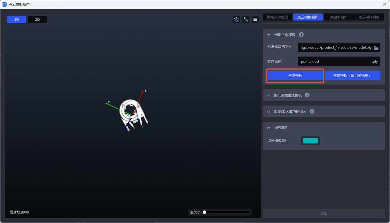
Generate Template:
Based on the standardized mesh file, downsample the entire model to generate a Point Cloud Template;
Suitable for most scenarios.
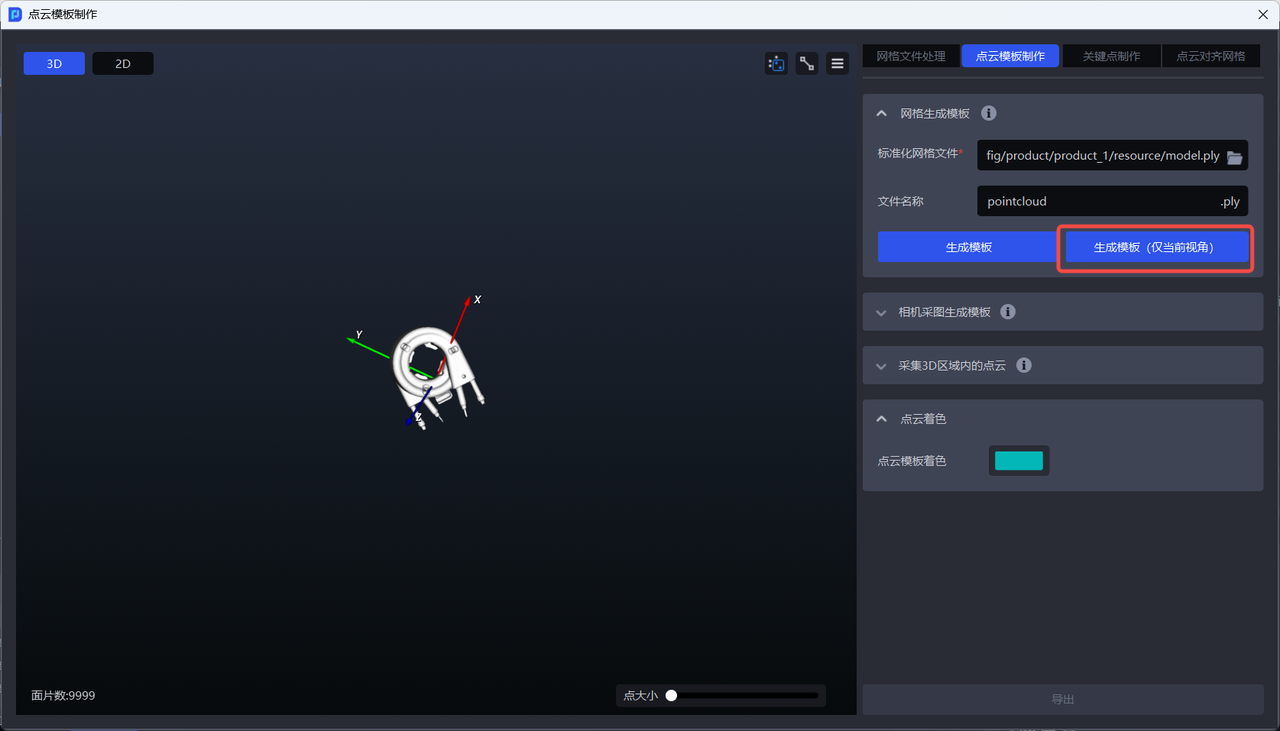
Generate Template** (Current View Only)**
Based on the standardized mesh file, use only the mesh file under the current view to generate the Point Cloud Template;
Suitable for ordered scenarios in which the workpiece placement pose is single and fixed. It is necessary to ensure that the view of the mesh file in the window is consistent with the view of the workpiece under the camera perspective in the real scenario.
Applicable Scenarios
Scenarios where the workpiece Point Cloud collected by the camera is highly consistent with the workpiece Point Cloud Template generated from the standardized mesh.
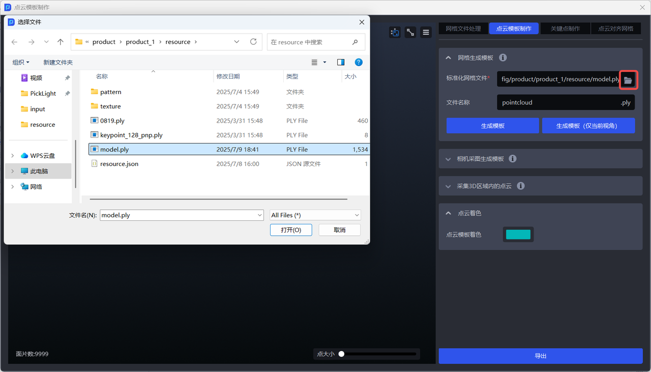
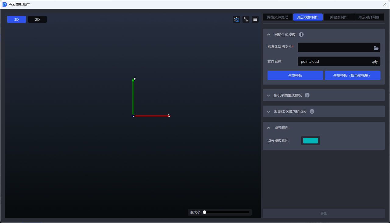
- Switch to the
Point Cloud Template Creationwindow

- Upload the standardized mesh file exported locally from
1. Mesh File Processing
- If you need to generate the full Point Cloud of the workpiece, click
Generate Template. The generated full Point Cloud Template is shown below.
- If you only need to generate the workpiece Point Cloud for the current view, click
Generate Template (Current View Only). The generated current-view Point Cloud Template is shown below.

2.1.2 Generate Template from Camera Capture
Feature Description
Capture two images with the camera (one with the workpiece and one without), then calculate the difference between the two images to obtain the workpiece Point Cloud Template. It is necessary to ensure that the camera capture view is the same and that no object other than the workpiece changes between the two captures.
Applicable Scenarios
Scenarios where the workpiece Point Cloud collected by the camera is poorly consistent with the workpiece Point Cloud Template generated from the standardized mesh.
⚠️Known Issue
When using camera capture to create a Point Cloud Template for relatively flat workpieces, there may be an issue where the Point Cloud cannot be captured or the Point Cloud is too sparse. The solution is to elevate the flat workpiece before capturing the image.
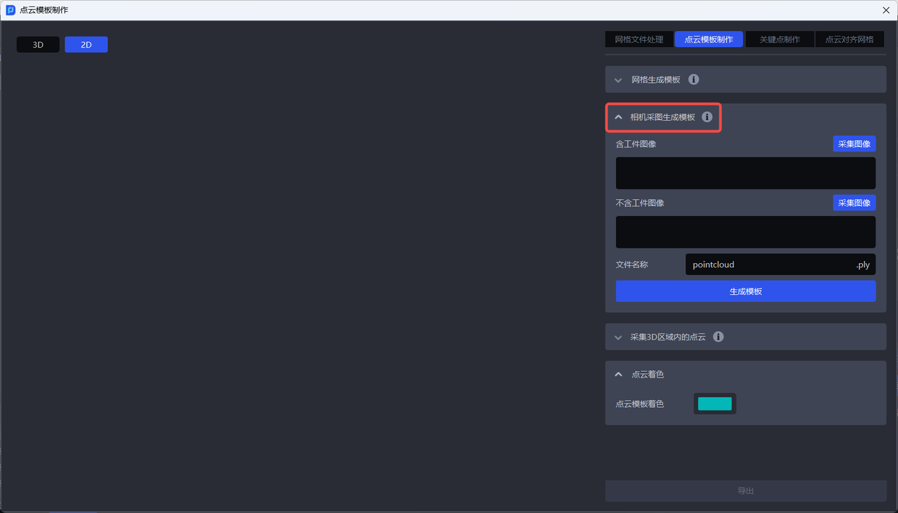
- Switch to the
Point Cloud Template Creationwindow
- Click
Generate Template from Camera Capture
Before using camera capture to generate a template, the camera must be connected and configured in the task information. For details, please refer to Camera Connection and Parameter Adjustment Guide
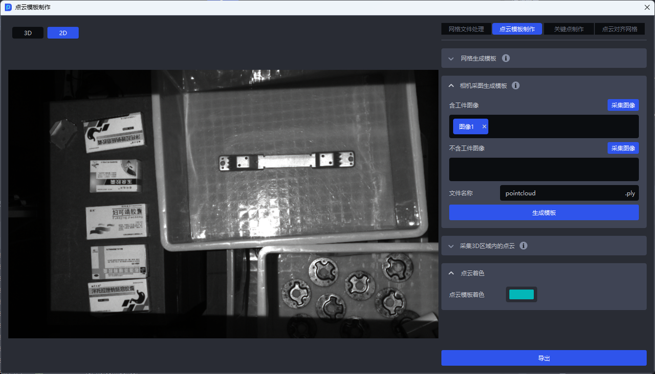
- In the
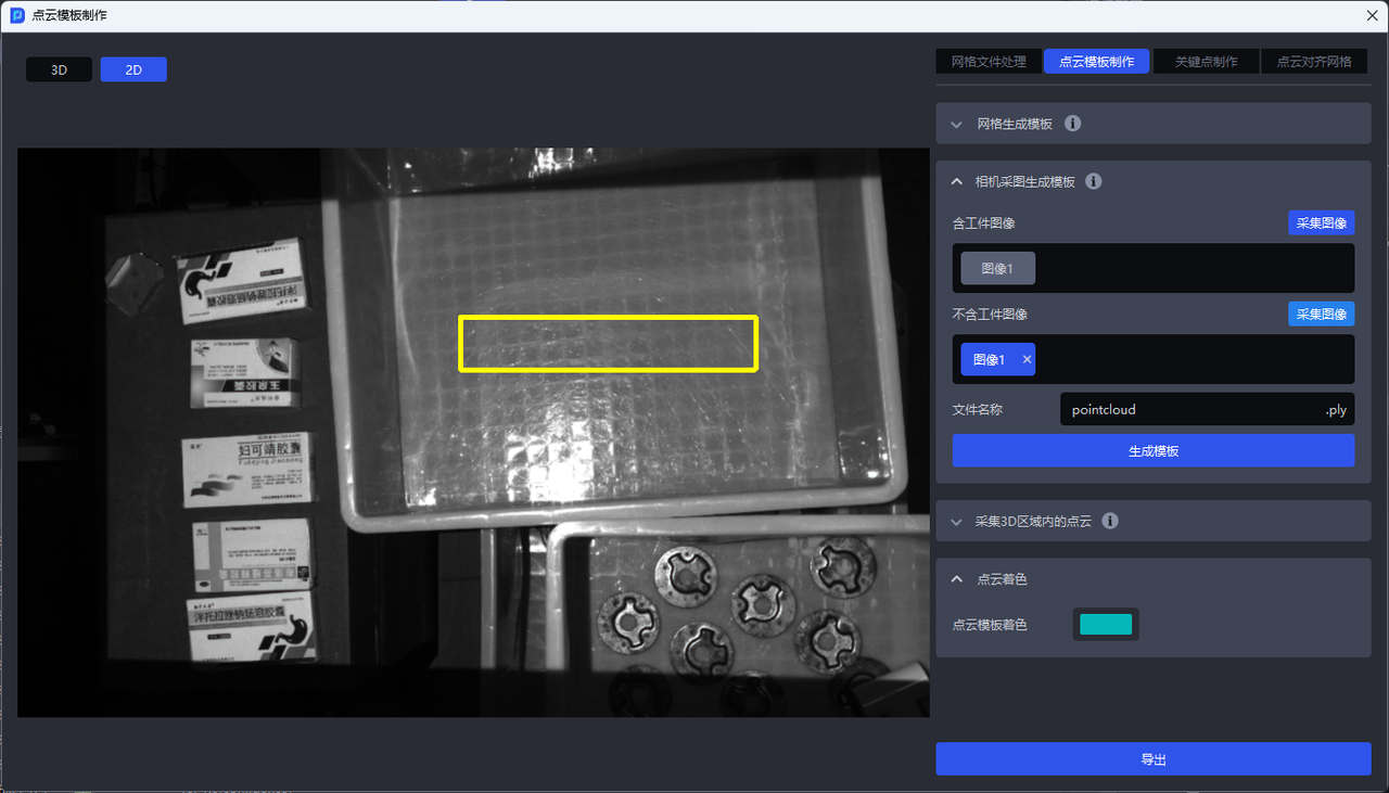
With Workpiece Imagecolumn, clickCapture Imageto capture an image containing the workpiece, as shown below
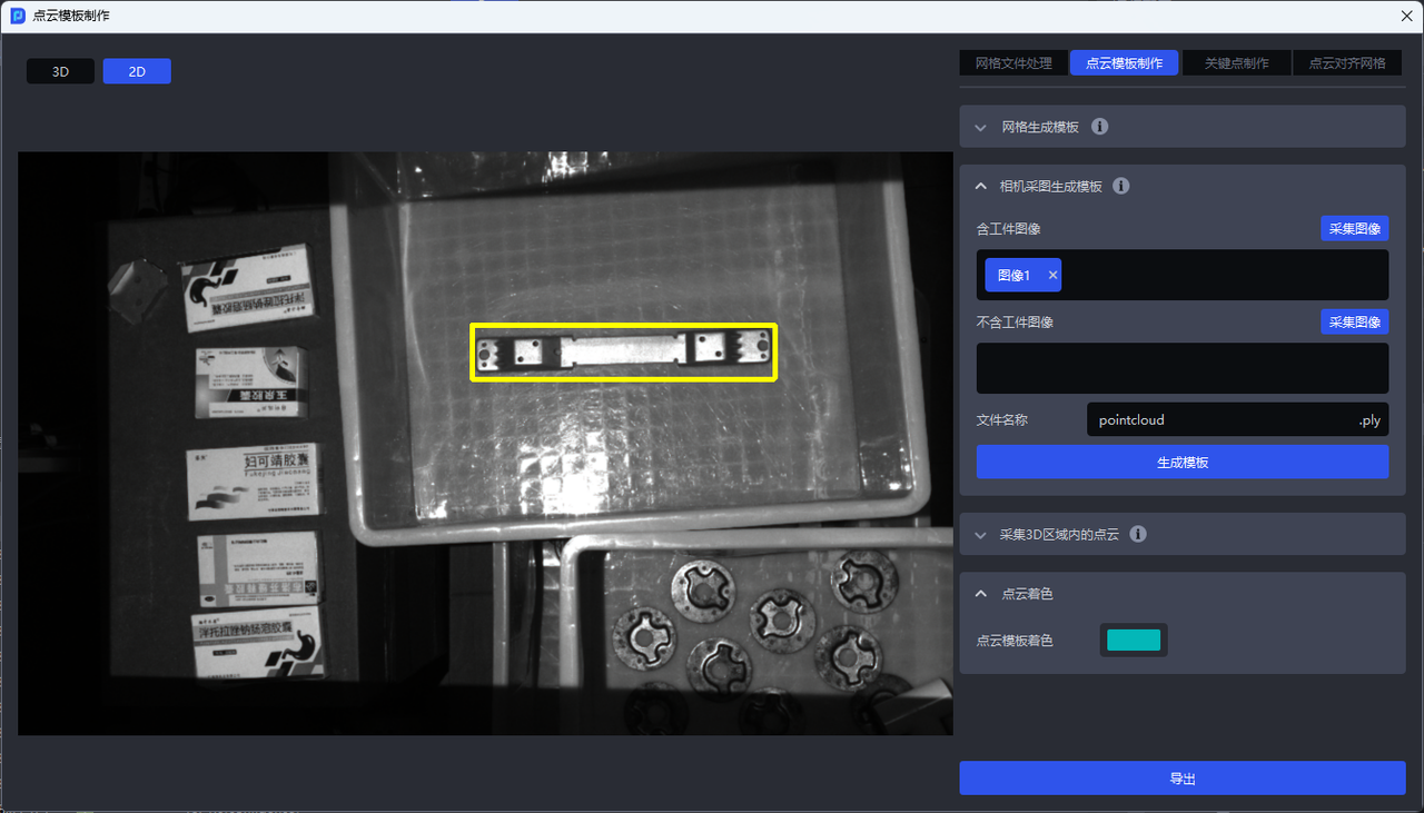
- Draw a 2D box around the workpiece on the captured image containing the workpiece, as shown below.
- In the
Without Workpiece Imagecolumn, clickCapture Imageto capture a Background image without the workpiece, as shown below
- Click
Generate Templateto generate the Point Cloud Template of the workpiece
2.1.3 Capture Point Cloud in 3D Region
In the Point Cloud image containing the workpiece captured by the camera, use a 3D bounding box to select the workpiece Point Cloud, then click Generate Template to obtain the Point Cloud Template file, as shown below.
- Switch to the
Point Cloud Template Creationwindow

- Click
Capture Point Cloud in 3D Region
Before capturing Point Cloud in a 3D region, the camera must be connected and configured in the task information. For details, please refer to Camera Connection and Parameter Adjustment Guide
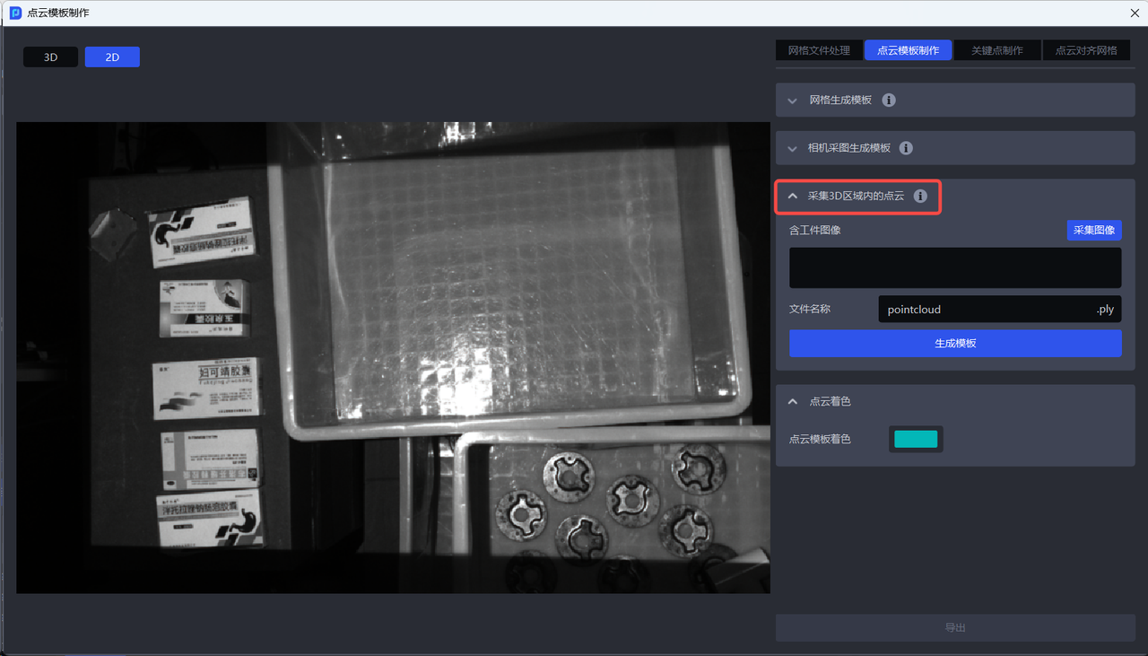
- In the
With Workpiece Imagecolumn, clickCapture Imageto capture an image containing the workpiece, as shown below
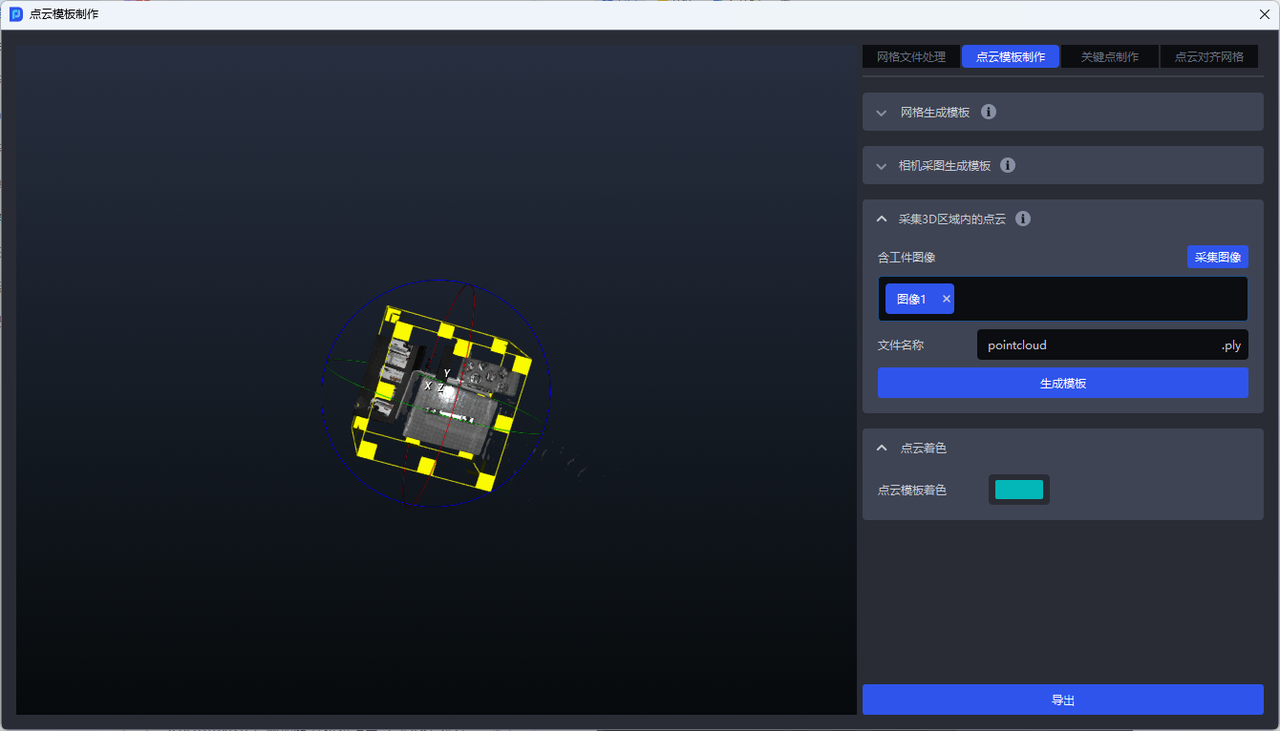
- Draw a box around the workpiece on the captured image
The left mouse button can change the view and zoom in/out, as shown below.
The right mouse button can adjust the size and angle of the 3D box, as shown below.
- After boxing the workpiece Point Cloud, click
Generate Templateto generate the Point Cloud Template of the workpiece
2.2 Select features to create a Point Cloud Template
When creating a Point Cloud Template, non-critical Point Cloud that may interfere with matching should be removed from the original Point Cloud, and then the most representative Point Cloud should be selected as the Point Cloud Template to optimize the subsequent matching process and improve matching efficiency and accuracy.
Please refer to Elements, Principles, and Examples of Point Cloud Template Creation and select features according to the task and workpiece in the actual scenario to create a Point Cloud Template.
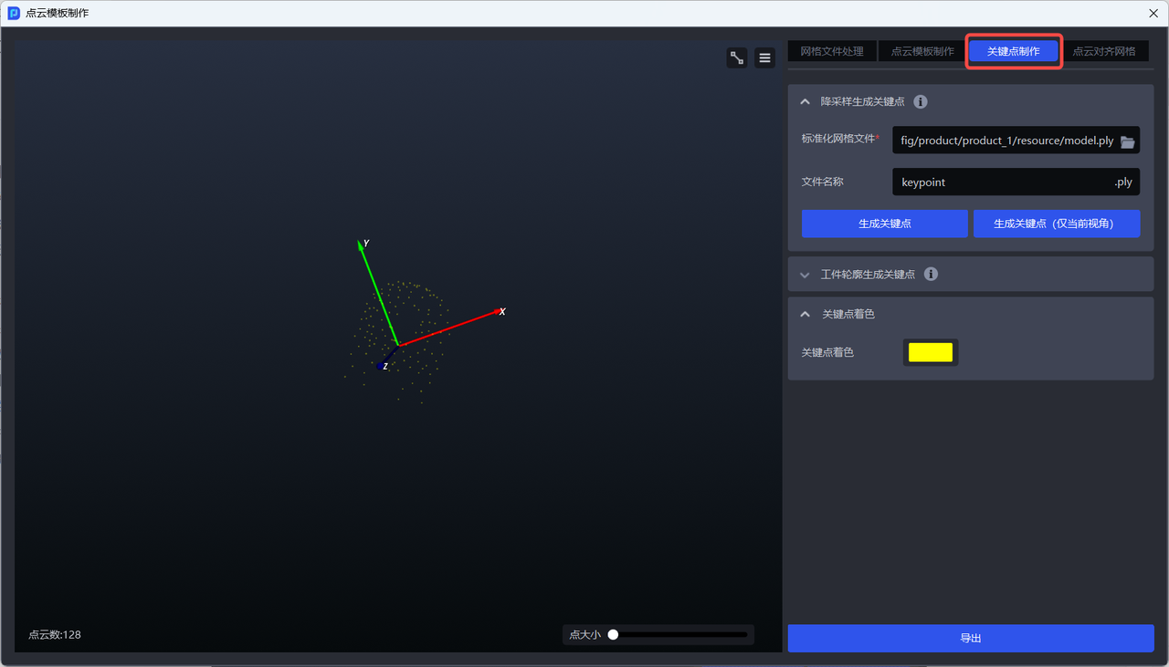
3. Keypoint creation
Keypoints are feature points in a 3D model that have clear semantic or geometric meaning. They are used to describe the local structure or global pose of a workpiece. In pose estimation based on keypoints, the overall position and pose of the workpiece are inferred by detecting the positions of these points.
3.1 Generate keypoints by downsampling
Feature Description
Use the imported standardized mesh file to generate evenly distributed keypoints across the entire workpiece with one click.
Applicable Scenarios
Applicable to most generic workpiece scenarios.
- Switch to the
Keypoint Creationwindow
- Upload the standardized mesh file
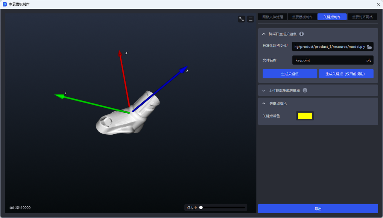
- If you need to generate the full set of keypoints for the workpiece, click
Generate Keypoints. The generated full set of keypoints is shown below.
- If you only need to generate keypoints for the current view, click
Generate Keypoints (Current View Only). The generated current-view keypoints are shown below.
3.2 Generate keypoints from the workpiece contour
Feature Description
Use the imported standardized mesh file to generate keypoints distributed on the workpiece contour with one click.
Applicable Scenarios
Applicable to generic workpiece scenarios where evenly distributed keypoints cannot correctly recognize workpiece characteristics, especially when the workpiece has features such as symmetry or front/back differences. Keypoints generated from the workpiece contour can achieve more accurate matching.
- Switch to the
Keypoint Creationwindow
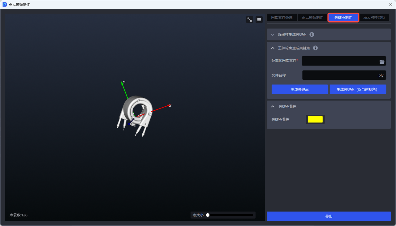
- Click
Generate Keypoints from Workpiece Contourand upload the standardized mesh file
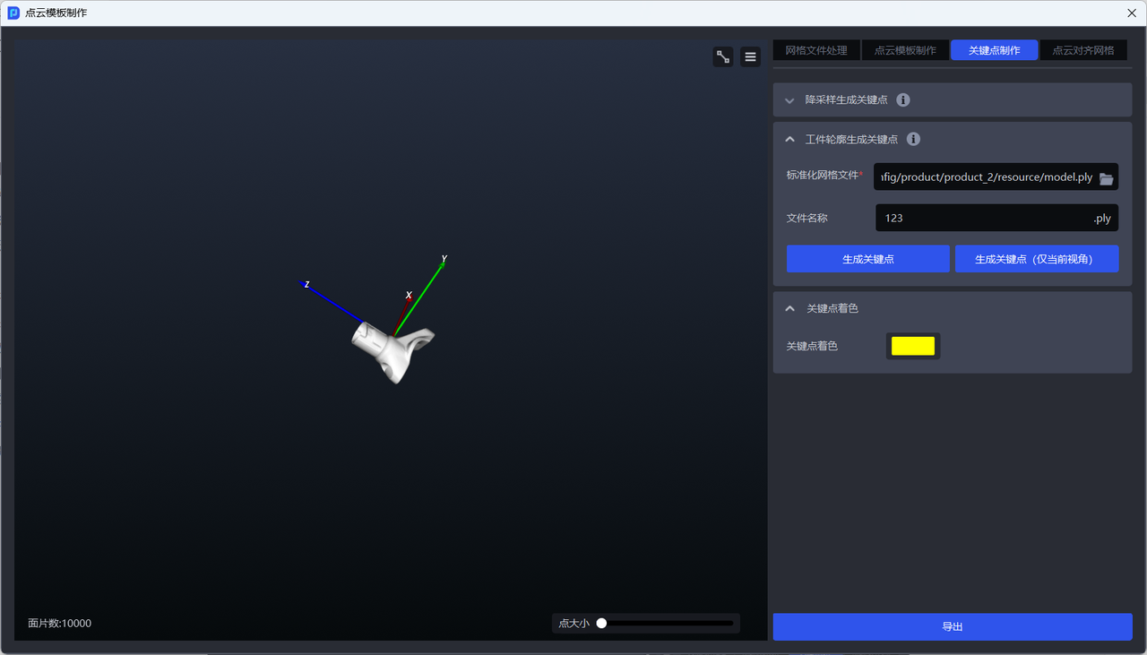
- If you need to generate the full set of keypoints for the workpiece, click
Generate Keypoints. The generated full set of keypoints is shown below.
- If you only need to generate keypoints for the current view, click
Generate Keypoints (Current View Only). The generated current-view keypoints are shown below.
4. Align Point Cloud to mesh
Feature Description
Align the coordinate system of the Point Cloud file with that of the standardized mesh file.
Applicable Scenarios
Applicable to generic workpiece scenarios where the coordinate system of the standardized mesh file is inconsistent with that of the workpiece Point Cloud Template (such as a Point Cloud Template generated by camera capture). Alignment is needed because the Point Cloud Template generated by camera capture uses the camera coordinate system as the origin by default. It must be aligned with the coordinates of the standardized mesh file so that the coordinate relationships among the mesh file, keypoints (generated from the mesh file and consistent with the mesh file coordinate system), and the workpiece Point Cloud Template are all consistent, allowing the generic workpiece to proceed normally with subsequent recognition and matching.
The camera must be connected before using
Align Point Cloud to Mesh
- Switch to the
Align Point Cloud to Meshwindow
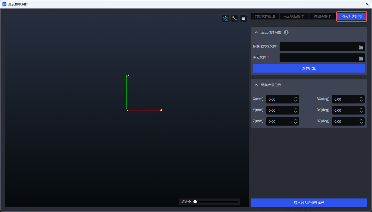
- Upload the standardized mesh file and the Point Cloud Template
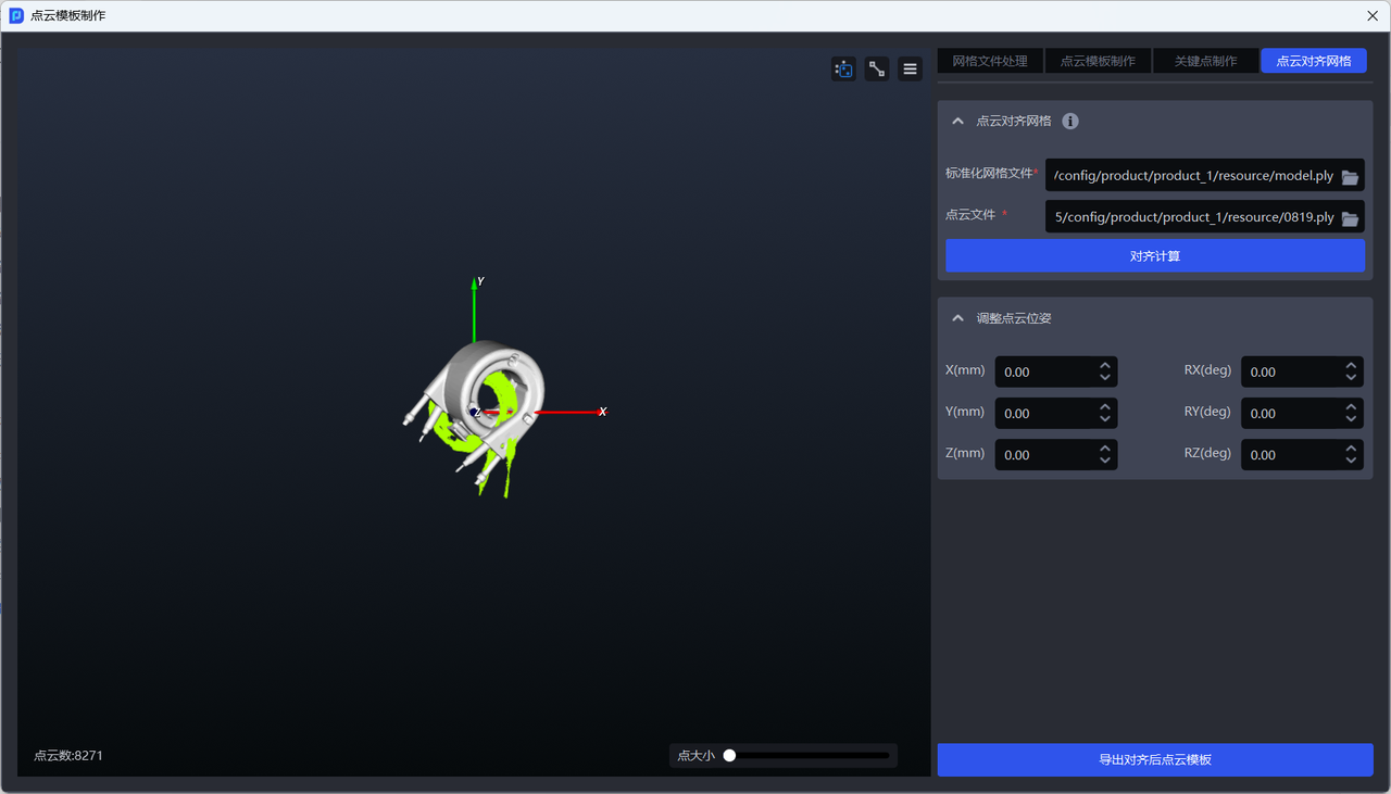
- Click
Compute Alignment
