Circular-Surface Target Object Vision Parameters Adjustment Guide
This article mainly introduces how to adjust Vision Parameters according to actual scenarios in circular-surface-based ordered loading/unloading and random picking.
1. 2D Recognition
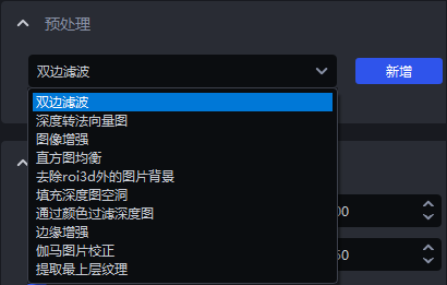
1.1 Preprocessing
The preprocessing of 2D Recognition processes the 2D image before the Deep Learning model performs computation.
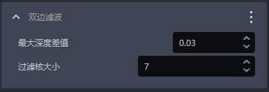
1.1.1 Bilateral Filtering
- Function
Image smoothing based on bilateral filtering.
- Parameter Description
| Parameter | Description | Default Value | Value Range |
|---|---|---|---|
| Maximum depth difference | The maximum depth difference for bilateral filtering | 0.03 | [0.01, 1] |
| Filter kernel size | The convolution kernel size for bilateral filtering | 7 | [1, 3000] |
1.1.2 Depth to Normal Vector Map
- Function
Calculate pixel normal vectors from the depth image and convert the image into a normal vector map.
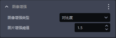
1.1.3 Image Enhancement
- Function
Common image enhancement operations, such as color saturation, contrast, brightness, and sharpness.
- Parameter Description
| Parameter | Description | Default Value | Value Range |
|---|---|---|---|
| Image enhancement type | Enhance a certain element of the image | Contrast | Color saturation, contrast, brightness, sharpness |
| Image enhancement Threshold | How much to enhance a certain element of the image | 1.5 | [0.1, 100] |
1.1.4 Histogram Equalization
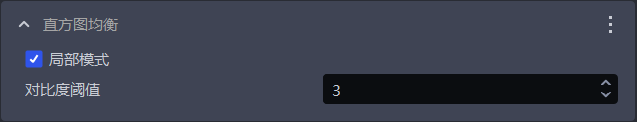
- Function
Improve image contrast.
- Parameter Description
| Parameter | Description | Default Value | Value Range |
|---|---|---|---|
| Local mode | Local or global histogram equalization. Checked means local histogram equalization; unchecked means global histogram equalization | Checked | / |
| Contrast Threshold | Contrast Threshold | 3 | [1,1000] |
1.1.5 Filter Depth Image by Color
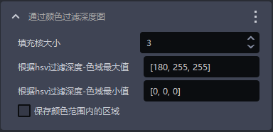
- Function
Filter the depth image according to color values.
- Parameter Description
| Parameter | Description | Default Value | Value Range |
|---|---|---|---|
| Fill kernel size | The size of color filling | 3 | [1,99] |
| Filter depth by HSV - maximum color range value | Maximum color value | [180,255,255] | [[0,0,0],[255,255,255]] |
| Filter depth by HSV - minimum color range value | Minimum color value | [0,0,0] | [[0,0,0],[255,255,255]] |
| Keep regions within the color range | Checked means keep the regions within the color range; unchecked means keep the regions outside the color range | / | / |
1.1.6 Gamma Image Correction
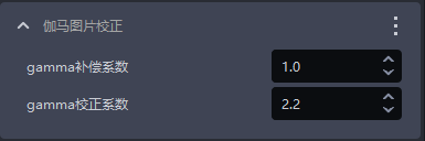
- Function
Gamma correction changes image brightness.
- Parameter Description
| Parameter | Description | Default Value | Value Range |
|---|---|---|---|
| Gamma compensation coefficient | If this value is less than 1, the image becomes darker; if this value is greater than 1, the image becomes brighter | 1 | [0.1,100] |
| Gamma correction coefficient | If this value is less than 1, the image becomes darker and is suitable for overly bright images; if this value is greater than 1, the image becomes brighter and is suitable for overly dark images | 2.2 | [0.1,100] |
1.1.7 Fill Holes in the Depth Image
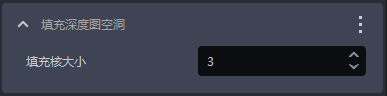
- Function
Fill hole regions in the depth image and smooth the filled depth image.
- Usage Scenario
Due to issues such as structural occlusion of the Target Object itself and uneven lighting, the depth image may miss some regions of the Target Object.
- Parameter Description
| Parameter | Description | Default Value | Value Range |
|---|---|---|---|
| Fill kernel size | The size of hole filling | 3 | [1,99] |
The fill kernel size can only be an odd number
- Parameter Tuning
Adjust according to the detection results. If the filling is excessive, reduce the Parameter; if the filling is insufficient, increase the Parameter.
- Example
1.1.8 Edge Enhancement
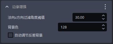
- Function
Set the edge parts of the texture in the image to the Background color or to a color that differs significantly from the Background color, so as to highlight the edge information of the Target Object.
- Usage Scenario
The edges are unclear because Target Objects occlude or overlap each other.
- Parameter Description
| Parameter | Description | Default Value | Parameter Range | Parameter Tuning Suggestion |
|---|---|---|---|---|
| Normal Z-direction filtering Threshold | The angle filtering Threshold between the normal vector corresponding to each point in the depth image and the positive Z-axis direction of the camera coordinate system. If the angle between a point's normal vector and the positive Z-axis direction of the camera coordinate system is greater than this Threshold, the color at the corresponding position of that point in the 2D image will be set to the Background color or to a color that differs significantly from the Background color | 30 | [0,180] | For flat Target Object surfaces, this Threshold can be smaller; for curved-surface Target Objects, increase it appropriately according to the degree of surface inclination |
| Background color | The RGB color Threshold of the Background color | 128 | [0,255] | |
| Automatically adjust contrast Background | Checked After automatically adjusting the contrast Background, the color of points in the 2D image whose angle is greater than the filtering Threshold is set to a color that differs significantly from the Background color; unchecked Without automatically adjusting the contrast Background, the color of points in the 2D image whose angle is greater than the filtering Threshold is set to the color corresponding to the Background color | Unchecked | / |
- Example
1.1.9 Extract the Topmost Texture
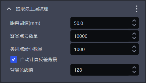
- Function
Extract the texture of the topmost or bottommost Target Object, while setting other regions to the Background color or to a color that differs significantly from the Background color.
- Usage Scenario
Factors such as poor lighting conditions, similar color textures, tight stacking, interleaved stacking, or occlusion may make it difficult for the model to distinguish the texture differences between upper and lower Target Objects, which can easily cause false detections.
- Parameter Description
| Parameter | Description | Default Value | Parameter Range | Unit | Parameter Tuning Suggestion |
|---|---|---|---|---|---|
| Distance Threshold (mm) | If the distance between a point and the topmost plane (bottommost plane) is lower than this Threshold, it is considered a point within the topmost plane (bottommost plane) and should be retained; otherwise it is considered a point in the lower layer (upper layer), and the color of points in the lower layer (upper layer) is set to the Background color or to a color that differs significantly from the Background color | 50 | [0.1, 1000] | mm | Generally adjust to 1/2 of the height of the Target Object |
| Clustered Point Cloud count | The expected number of points participating in clustering, that is, the number of sampled Point Cloud points within the ROI 3D region | 10000 | [1,10000000] | / | The more clustered Point Cloud count, the lower the model Inference speed but the higher the accuracy; the fewer clustered Point Cloud count, the higher the model Inference speed but the lower the accuracy |
| Minimum number of class points | The minimum number of points used to filter classes | 1000 | [1, 10000000] | / | / |
| Automatically calculate contrast Background | Checked After automatically calculating the contrast Background, other regions outside the topmost (bottommost) layer in the 2D image are set to a color that differs significantly from the Background color Threshold; unchecked Without automatically calculating the contrast Background, other regions outside the topmost (bottommost) layer in the 2D image are set to the color corresponding to the Background color Threshold | Checked | / | / | / |
| Background color Threshold | The RGB color Threshold of the Background color | 128 | [0,255] | / | / |
- Example
1.1.10 Remove the image Background outside roi3d
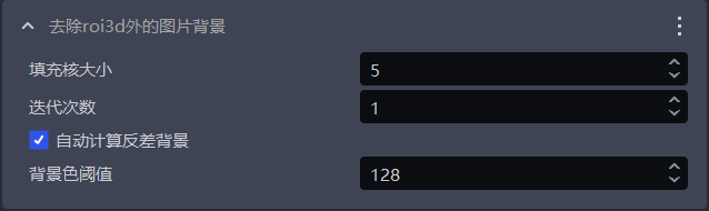
- Function
Remove the Background in the 2D image except for the ROI3D region.
- Usage Scenario
There is too much Background noise in the image, affecting detection results.
- Parameter Description
| Parameter Name | Description | Default Value | Value Range |
|---|---|---|---|
| Fill kernel size | The size of hole filling | 5 | [1,99] |
| Iteration count | The iteration count for image Dilation | 1 | [1,99] |
| Automatically calculate contrast Background | Checked After automatically calculating the contrast Background, regions outside the roi in the 2D image are set to a color that differs significantly from the Background color Threshold; unchecked Without automatically calculating the contrast Background, regions outside the roi in the 2D image are set to the color corresponding to the Background color Threshold | Checked | / |
| Background color Threshold | The RGB color Threshold of the Background color | 128 | [0,255] |
The fill kernel size can only be an odd number
- Parameter Tuning
If you need to remove more Background noise from the image, reduce the fill kernel size.
- Example
1.2 Instance Segmentation
1.2.1 Scaling ratio
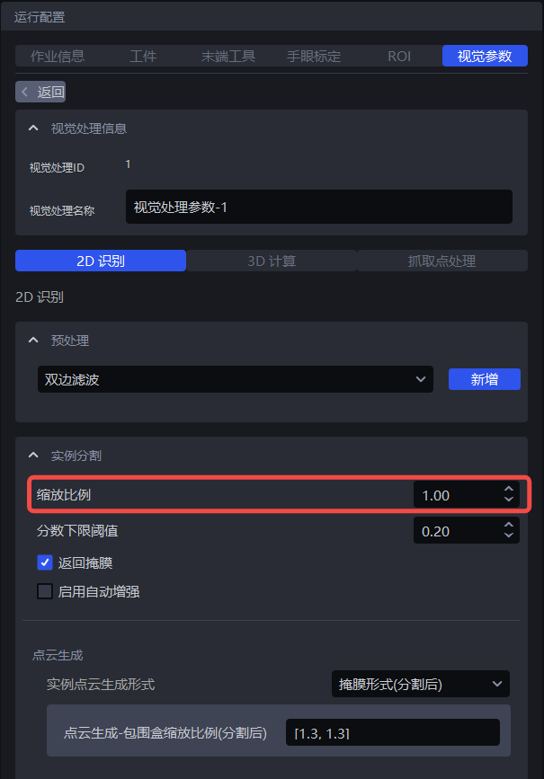
- Function
Improve the accuracy and recall of 2D Recognition by uniformly scaling the original image before Inference.
- Usage Scenario
If the detection result is poor (for example, no instance is detected, missed recognition occurs, one bounding box covers multiple instances, or the bounding box does not fully cover an instance), this function should be adjusted.
Parameter Description
Default value: 1.0
Value range: [0.01, 3.00]
Step size: 0.01
Parameter Tuning
- Run with the default value and check the detection result in the visualization window. If no instance is detected, missed recognition occurs, one bounding box covers multiple instances, or the bounding box does not fully cover an instance, this function should be adjusted.
If you cannot obtain a good detection result after trying all scaling ratios, you can adjust the ROI region
As shown in the figure below, when the scaling ratio is 0.7, the detection result improves significantly, so 0.7 can be determined as the lower limit of the scaling ratio range.
When the scaling ratio is 2, the detection result decreases significantly, so 2 can be determined as the upper limit of the scaling ratio range.
1.2.2 Lower Confidence Threshold
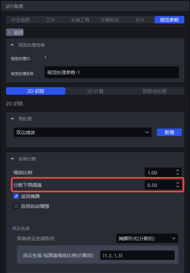
- Function
Only retain recognition results whose Deep Learning model recognition scores are higher than the lower Confidence Threshold.
- Usage Scenario
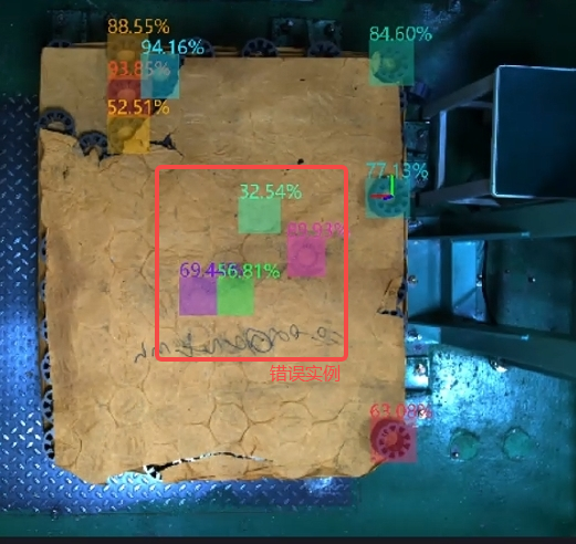
When the detected instances enclosed by the detection boxes do not meet expectations, this function can be adjusted.
- Parameter Description
Default value: 0.5
Value range: [0.01, 1.00]
Parameter Tuning
If the model detects too few instances, reduce this Threshold; if the value is too small, it may affect image recognition accuracy.
If incorrect instances are detected because the lower Confidence Threshold is too small and these incorrect instances need to be removed, increase this Threshold; if the value is too large, the number of retained detection results may become zero, with no output result.
1.2.3 Enable Auto Enhancement
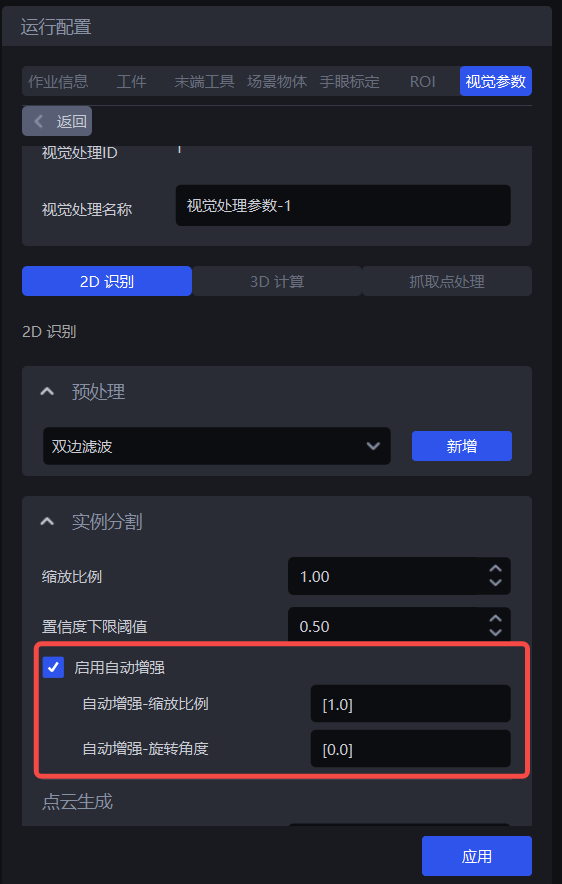
- Function
Combine all values in the input scaling ratios and rotation angles for Inference, and return all results after combination that are greater than the configured lower Confidence Threshold, which can improve model Inference accuracy, but will increase the time consumed.
- Usage Scenario
A single scaling ratio cannot meet actual scenario requirements, resulting in incomplete detection, or the object placement tilt is relatively large.
- Example
If auto enhancement - scaling ratio is set to [0.8, 0.9, 1.0] and auto enhancement - rotation angle is set to [0, 90.0] then the values in the scaling ratios and rotation angles will be combined pairwise. The model will automatically generate 6 images for Inference, and finally merge these 6 Inference results together and output the results greater than the lower Confidence Threshold.
Auto Enhancement - Scaling Ratio
- Function
Scale the original image multiple times and perform Inference multiple times, then output the combined Inference result.
- Usage Scenario
A single scaling ratio cannot meet actual scenario requirements, resulting in incomplete detection.
- Parameter Description
Default value: [1.0]
Value range: the range of each scaling ratio is [0.1, 3.0]
Multiple scaling ratios can be set, separated by English commas.
- Parameter Tuning
Enter multiple scaling ratios from 1.2.1 Scaling ratio that produce better detection results.
Auto Enhancement - Rotation Angle
- Function
Rotate the original image multiple times and perform Inference multiple times, then output the combined Inference result.
- Usage Scenario
Use when the object placement deviates significantly from the coordinate axes.
- Parameter Description
Default value: [0.0]
Value range: the value range of each rotation angle is [0, 360]
Multiple rotation angles can be set, separated by English commas.
- Parameter Tuning
Adjust auto enhancement - rotation angle according to the object angle in the actual scenario. The tilt angle can be judged based on sack patterns and bag opening shapes, or carton edges and brand logos.
1.3 Point Cloud Generation
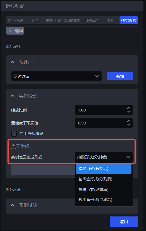
| Instance Point Cloud generation form | Mask form (after segmentation) | - | Use the segmented instance Mask to generate the Point Cloud |
| Bounding box form (after segmentation) | Bounding box scaling ratio (after segmentation) | Use the segmented instance bounding box to generate the Point Cloud | |
| Whether color is needed when generating the Point Cloud (after segmentation) | Whether the generated instance Point Cloud needs attached colors | ||
| Mask form (after filtering) | - | Use the filtered instance Mask to generate the Point Cloud | |
| Bounding box form (after filtering) | Bounding box scaling ratio (after filtering) | Use the filtered instance bounding box to generate the Point Cloud | |
| Whether color is needed when generating the Point Cloud (after filtering) | Whether the generated instance Point Cloud needs attached colors |
If acceleration is not needed, there is no need to use the instance filtering function. Use Mask form (after segmentation) or bounding box form (after segmentation) to generate the instance Point Cloud. You can view the generated instance Point Cloud in the \ProjectName\data\PickLight\HistoricalDataTimestamp\Builder\pose\input folder under the project storage folder;
If acceleration is needed, you can use the instance filtering function to filter instances, and use Mask form (after filtering) or bounding box form (after filtering) to generate the instance Point Cloud. You can view the generated instance Point Cloud in the \ProjectName\data\PickLight\HistoricalDataTimestamp\Builder\pose\input folder under the project storage folder.
1.4 Instance Filtering
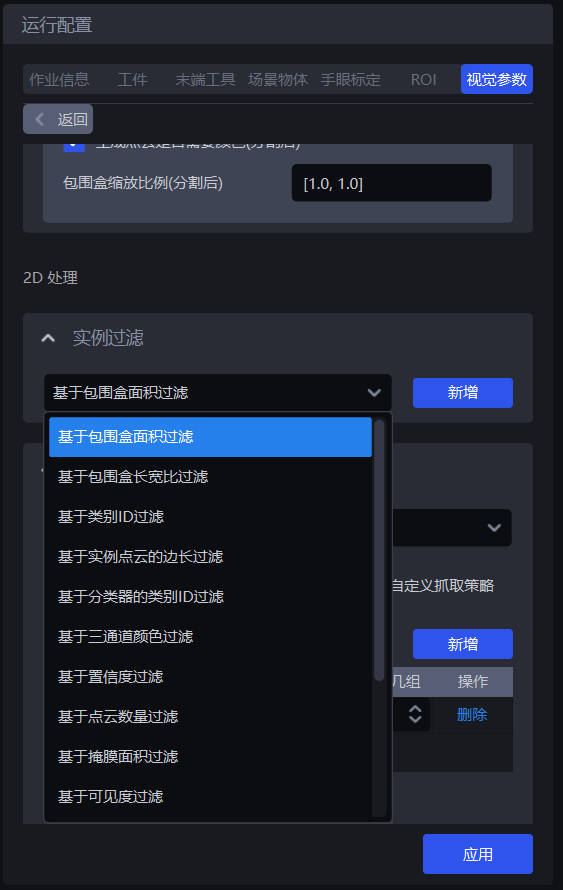
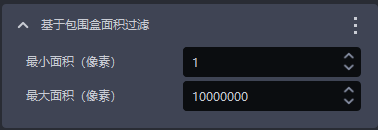
1.4.1 Filter Based on Bounding Box Area
- Function Introduction
Filter based on the pixel area of the detected instance bounding box.
- Usage Scenario
Suitable for scenarios where instance bounding box areas differ greatly. By setting the upper and lower limits of the bounding box area, image noise can be filtered out, improving image recognition accuracy and preventing noise from increasing the time required for subsequent processing.
- Parameter Description
| Parameter | Description | Default Value | Parameter Range | Unit |
|---|---|---|---|---|
| Minimum area (pixels) | This Parameter sets the minimum filtering area of the bounding box. Instances whose bounding box area is lower than this value will be filtered out | 1 | [1, 10000000] | pixels |
| Maximum area (pixels) | This Parameter sets the maximum filtering area of the bounding box. Instances whose bounding box area is higher than this value will be filtered out | 10000000 | [2, 10000000] | pixels |
- Example
Run with the default value. You can view the bounding box area of each instance in the log, as shown below.
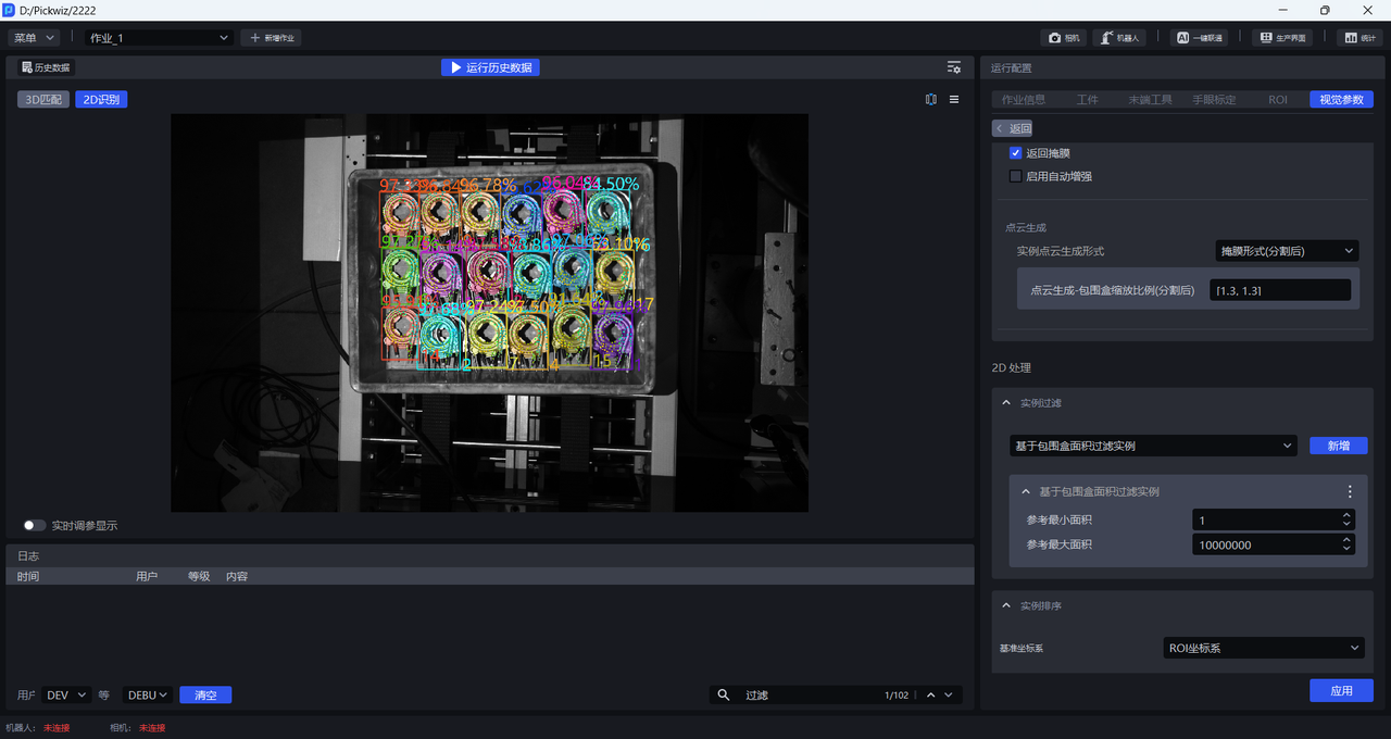
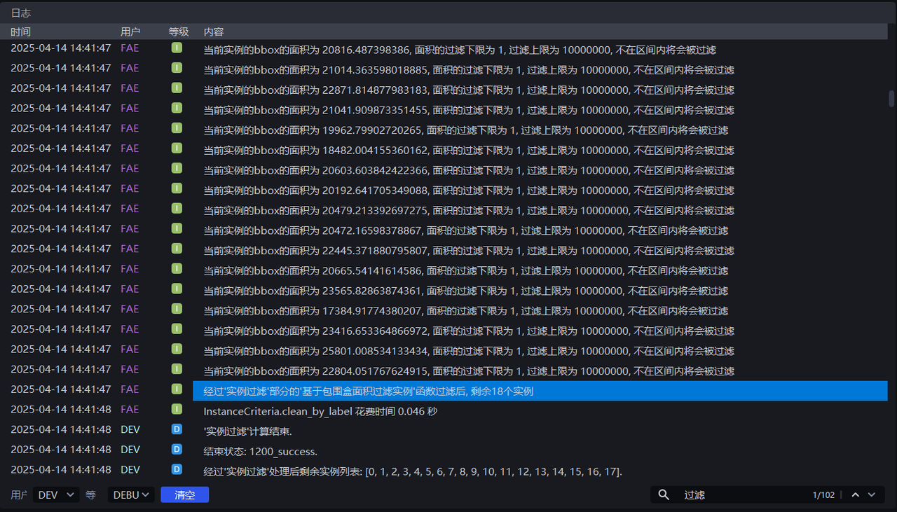
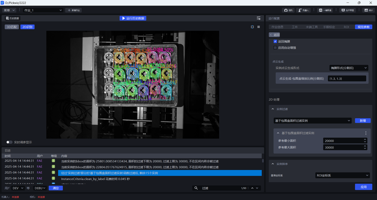
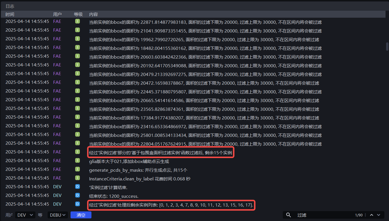
Adjust minimum area and maximum area according to the bounding box area of each instance. For example, if minimum area is set to 20000 and maximum area is set to 30000, instances whose pixel area is less than 20000 or greater than 30000 can be filtered out. The instance filtering process can be viewed in the log.
1.4.2 Filter Based on Bounding Box Aspect Ratio
- Function Introduction
Instances whose bounding box aspect ratios are outside the specified range will be filtered out.
- Usage Scenario
Suitable for scenarios where the aspect ratios of instance bounding boxes differ greatly.
- Parameter Description
| Parameter | Description | Default Value | Parameter Range |
|---|---|---|---|
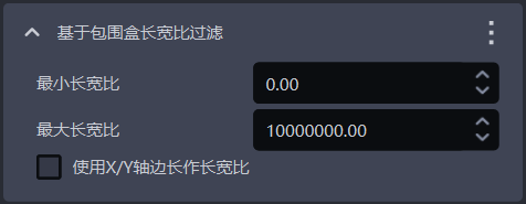
| Minimum aspect ratio | The minimum value of the bounding box aspect ratio. Instances whose bounding box aspect ratio is lower than this value will be filtered out | 0 | [0, 10000000] |
| Maximum aspect ratio | The maximum value of the bounding box aspect ratio. Instances whose bounding box aspect ratio is higher than this value will be filtered out | 10000000 | [0, 10000000] |
| Use X/Y axis side length as aspect ratio | By default, this is unchecked, and the length ratio of the longer side / shorter side of the bounding box is used as the aspect ratio, which is suitable when the lengths of the longer and shorter sides of the bounding box differ greatly; When checked, the length ratio of the bounding box side on the X-axis / side on the Y-axis in the pixel coordinate system is used as the aspect ratio, which is suitable when the longer-side / shorter-side ratio of most normal instance bounding boxes is similar, but some abnormally recognized instance bounding boxes differ greatly in the ratio of their X-axis length to Y-axis length. | Unchecked | / |
1.4.3 Filter Instances Based on Class ID
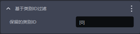
- Function Introduction
Filter according to the instance class.
- Usage Scenario
Suitable for scenarios where the incoming materials contain multiple types of Target Objects.
- Parameter Description
| Parameter | Description | Default Value |
|---|---|---|
| Retained class IDs | Retain instances whose class IDs are in the list; instances whose class IDs are not in the list will be filtered out | [0] |
- Example
1.4.4 Filter Based on Side Lengths of Instance Point Cloud
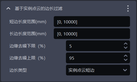
- Function Introduction
Filter according to the long side and short side of the instance Point Cloud.
- Usage Scenario
Suitable for scenarios where the distances of the instance Point Cloud on the x-axis or y-axis differ greatly. By setting the distance range of the instance Point Cloud, image noise can be filtered out, improving image recognition accuracy and preventing noise from increasing the time required for subsequent processing.
- Parameter Description
| Parameter | Description | Default Value | Parameter Range | Unit |
|---|---|---|---|---|
| Short-side length range (mm) | The side length range of the short side of the Point Cloud | [0, 10000] | [0, 10000] | mm |
| Long-side length range (mm) | The side length range of the long side of the Point Cloud | [0, 10000] | [0, 10000] | mm |
| Lower edge denoising limit (%) | Extract the lower percentage limit of X/Y values (camera coordinate system) in the instance Point Cloud, and remove the Point Cloud outside the upper and lower limits to avoid noise affecting length calculation | 5 | [0, 100] | / |
| Upper edge denoising limit (%) | Extract the upper percentage limit of X/Y values (camera coordinate system) in the instance Point Cloud, and remove the Point Cloud outside the upper and lower limits to avoid noise affecting length calculation | 95 | [0, 100] | / |
| Side length type | Filter by the long side and short side of the instance Point Cloud. Instances whose long side or short side length is not within the range will be filtered out | Instance Point Cloud short side | Instance Point Cloud short side; Instance Point Cloud long side; Instance Point Cloud long side and short side | / |
- Example
1.4.5 Class ID Filtering Based on Classifier
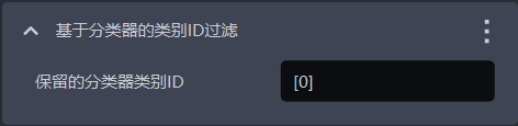
- Function Introduction
Filter instances based on classifier class ID. Instances not in the reference classes will be filtered out.
- Usage Scenario
In multi-class Target Object scenarios, the vision model may detect multiple types of Target Objects, but the actual task may require only one category of Target Object. In this case, this function can be used to filter out unnecessary Target Objects.
- Parameter Description
The default value is [0], which means that instances with class ID 0 are retained by default. Instances whose class ID is not in the list will be filtered out.
1.4.6 Filter Based on Three-Channel Colors
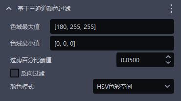
- Function Introduction
Instances can be filtered out by three-channel color Thresholds (HSV or RGB).
- Usage Scenario
Cases where incorrect instances and correct instances are clearly distinguishable by color.
- Parameter Description
| Parameter | Description | Default Value | Value Range |
|---|---|---|---|
| Maximum color range value | Maximum color value | [180,255,255] | [[0,0,0],[255,255,255]] |
| Minimum color range value | Minimum color value | [0,0,0] | [[0,0,0],[255,255,255]] |
| Filtering percentage Threshold | Color pass-rate Threshold | 0.05 | [0,1] |
| Reverse filtering | Checked means remove instances whose proportion outside the color range is lower than the Threshold; unchecked means remove instances whose proportion within the color range in the instance image is lower than the Threshold | Unchecked | / |
| Color mode | The color space selected in color filtering | HSV color space | RGB color space HSV color space |
- Example
1.4.7 Filter Based on Confidence
- Function Introduction
Filter according to the Confidence scores of instances.
- Usage Scenario
Suitable for scenarios where the Confidence values of instances differ greatly.
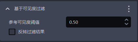
- Parameter Description
| Parameter | Description | Default Value | Parameter Range |
|---|---|---|---|
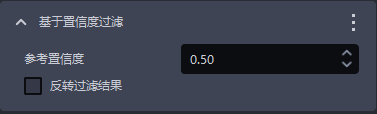
| Reference Confidence | Retain instances with Confidence greater than the Threshold, and filter out instances with Confidence lower than the Threshold. | 0.5 | [0,1] |
| Reverse filtering result | After reversal, retain instances with visibility Confidence lower than the Threshold, and filter out instances with Confidence greater than the Threshold. | Unchecked | / |
- Example
1.4.8 Filter Based on Point Cloud Count
- Function Introduction
Filter according to the number of downsampled instance Point Cloud points.
- Usage Scenario
The instance Point Cloud contains much noise.
- Parameter Description
| Parameter | Description | Default Value | Parameter Range |
|---|---|---|---|
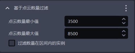
| Minimum Point Cloud count | The minimum value of the Point Cloud count | 3500 | [1, 10000000] |
| Maximum Point Cloud count | The maximum value of the Point Cloud count | 8500 | [2, 10000000] |
| Filter instances whose count is within the interval | Checked means filter instances whose Point Cloud count is within the interval between the minimum and maximum values; unchecked means filter instances whose Point Cloud count is outside the interval | Unchecked | / |
1.4.9 Filter Based on Mask Area
- Function Introduction
Filter image masks according to the sum of detected instance Mask pixels (that is, the pixel area).
- Usage Scenario
Suitable for scenarios where instance Mask areas differ greatly. By setting the upper and lower limits of the Mask area, noise in image masks can be filtered out, improving image recognition accuracy and preventing noise from increasing the time required for subsequent processing.
- Parameter Setting Description
| Parameter Name | Description | Default Value | Parameter Range | Unit |
|---|---|---|---|---|
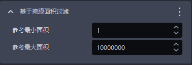
| Reference minimum area | This Parameter is used to set the minimum filtering area of the Mask. Instances whose Mask area is lower than this value will be filtered out | 1 | [1, 10000000] | pixels |
| Reference maximum area | This Parameter is used to set the maximum filtering area of the Mask. Instances whose Mask area is higher than this value will be filtered out | 10000000 | [2, 10000000] | pixels |
- Example
1.4.10 Filter Based on Visibility
- Function Introduction
Filter according to the visibility scores of instances.
- Usage Scenario
Suitable for scenarios where the visibility of instances differs greatly.
- Parameter Description
| Parameter | Description | Default Value | Parameter Range |
|---|---|---|---|
| Reference visibility Threshold | Retain instances whose visibility is greater than the Threshold, and filter out instances whose visibility is lower than the Threshold. Visibility is used to judge the visible degree of instances in the image. The more the Target Object is occluded, the lower the visibility. | 0.5 | [0,1] |
| Reverse filtering result | After reversal, retain instances whose visibility is lower than the Threshold, and filter out instances whose visibility is greater than the Threshold. | Unchecked | / |
1.4.11 Filter Instances with Overlapping Bounding Boxes
- Function Introduction
Filter instances whose bounding boxes intersect and overlap.
- Usage Scenario
Suitable for scenarios where instance bounding boxes intersect each other.
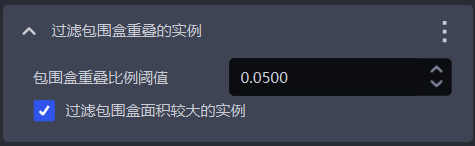
- Parameter Description
| Parameter | Description | Default Value | Parameter Range |
|---|---|---|---|
| Bounding box overlap ratio Threshold | The ratio Threshold of the intersection area of bounding boxes to the area of the instance bounding box | 0.05 | [0, 1] |
| Filter the instance with the larger bounding box area | Checked means filter the instance with the larger area among two instances whose bounding boxes intersect; unchecked means filter the instance with the smaller area among two instances whose bounding boxes intersect | Checked | / |
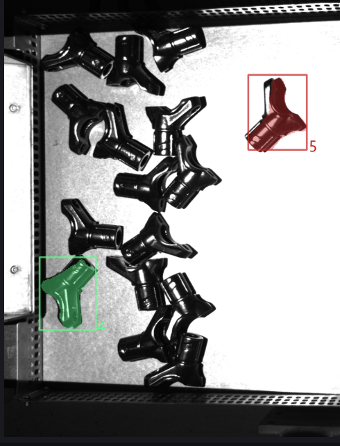
- Example
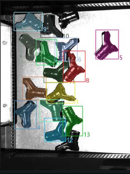
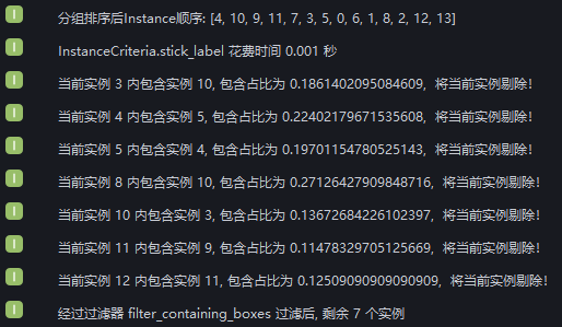
Newly added filter enclosed instances. Run with the default value and check the intersection of instance bounding boxes in the log. After instance filtering, 2 instances remain.
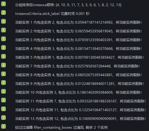
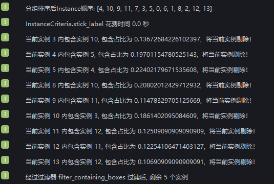
From the log, it can be seen that 12 instances were filtered out due to bounding box intersection, leaving 2 instances whose bounding boxes do not intersect.
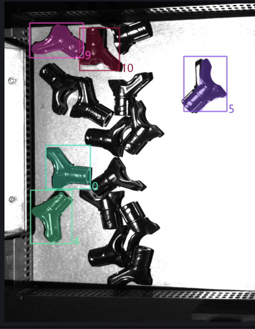
Set bounding box overlap ratio Threshold to 0.1 and check whether to filter larger instances. View the instance filtering process in the log. 9 instances were filtered out because the ratio of their bounding box intersection area to their bounding box area was greater than 0.1, 3 instances were retained because the ratio was less than 0.1, and 2 instances had no bounding box intersection.
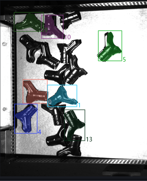
Set bounding box overlap ratio Threshold to 0.1 and uncheck whether to filter larger instances. View the instance filtering process in the log. The ratio of the bounding box intersection area to the instance bounding box area of 9 instances was greater than 0.1, but 2 of them were retained because their bounding box areas were smaller than the intersecting instances, so 7 instances were filtered out; 3 instances were retained because the ratio of the bounding box intersection area to the instance bounding box area was less than 0.1; 2 instances had no bounding box intersection.
1.4.12 [Master] Filter Instances with Concave/Convex Masks Based on Mask / Circumscribed Polygon Area Ratio
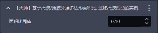
- Function Introduction
Calculate the area ratio of Mask / circumscribed polygon. If it is lower than the configured Threshold, the instance will be filtered out.
- Usage Scenario
Suitable for cases where the Target Object Mask has jagged / concave-convex edges.
- Parameter Description
| Parameter | Description | Default Value | Value Range |
|---|---|---|---|
| Area ratio Threshold | The Threshold of the Mask / convex hull area ratio. If it is lower than the configured Threshold, the instance will be filtered out. | 0.1 | [0,1] |
1.4.13 [Master] Filter Based on Average Point Cloud Distance
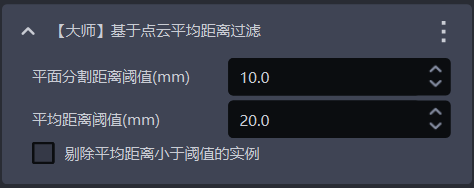
- Function Introduction
Filter based on the average distance from points in the Point Cloud to the fitted plane, removing uneven instance Point Clouds.
- Usage Scenario
Suitable for scenarios where planar Target Object Point Clouds are bent.
- Parameter Description
| Parameter | Description | Default Value | Parameter Range | Unit |
|---|---|---|---|---|
| Plane segmentation distance Threshold (mm) | Extract a plane from the bent instance Point Cloud. Points whose distance to the plane is less than this Threshold are regarded as points on the plane | 10 | [-1000, 1000] | mm |
| Average distance Threshold (mm) | The average distance from points in the instance Point Cloud to the extracted plane | 20 | [-1000, 1000] | mm |
| Remove instances whose average distance is lower than the Threshold | Checked means filter instances whose average distance from points to the extracted plane is lower than the average distance Threshold; unchecked means filter instances whose average distance from points to the extracted plane is greater than the average distance Threshold | Unchecked | / | / |
1.4.14 [Master] Filter Occluded Instances Based on Mask / Bounding Box Area Ratio
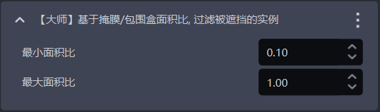
- Function Introduction
Calculate the Mask / bounding box area ratio. Instances whose ratio is not within the minimum and maximum range will be filtered out.
- Usage Scenario
Used to filter instances of occluded Target Objects.
- Parameter Description
On the contrary, it indicates possible occlusion.
| Parameter | Description | Default Value | Value Range |
|---|---|---|---|
| Minimum area ratio | The lower limit of the Mask / bounding box area ratio range. The smaller the ratio, the higher the degree of occlusion of the instance | 0.1 | [0,1] |
| Maximum area ratio | The upper limit of the Mask / bounding box area ratio range. The closer the ratio is to 1, the lower the degree of occlusion of the instance | 1.0 | [0,1] |
1.4.15 [Master] Determine Whether All Topmost Instances Are Fully Detected
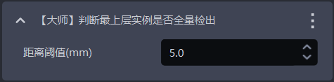
- Function Introduction
One of the foolproof mechanisms. It determines whether all topmost instances have been detected. If there are undetected topmost instances, an error will be reported and the workflow will end.
- Usage Scenario
Suitable for scenarios where one photo is used for multiple picks or where picking must be performed in sequence, preventing missed picks that affect subsequent operations due to incomplete instance detection.
- Parameter Description
| Parameter | Description | Default Value | Parameter Range | Unit | Parameter Tuning |
|---|---|---|---|---|---|
| Distance Threshold | Used to determine the topmost Target Object. If the distance between a point and the highest point of the Target Object Point Cloud is less than the distance Threshold, the point is considered part of the topmost Point Cloud; otherwise, it is not considered part of the topmost Point Cloud. | 5 | [0.1, 1000] | mm | Should be smaller than the height of the Target Object |
1.5 Instance Sorting
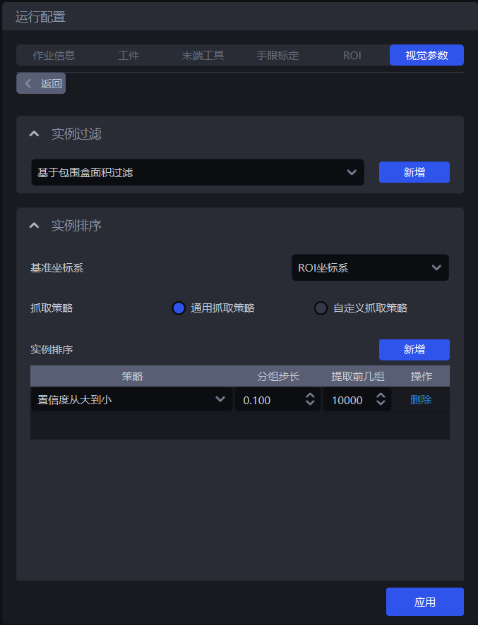
- Function Introduction
Group, sort, and extract instances according to the selected strategy.
- Usage Scenario
Applicable to depalletizing, random picking, and ordered loading/unloading scenarios.
If sorting is not needed, you do not need to configure a specific strategy.
1.5.1 Reference Coordinate System

- Function Introduction
Set a unified coordinate system for all instances to group and sort instances.
- Usage Scenario
Applicable to depalletizing scenarios, random picking scenarios, and ordered loading/unloading scenarios.
When using coordinate-related strategies, the reference coordinate system should be set first
- Parameter Description
| Parameter | Description | Illustration |
|---|---|---|
| Default coordinate system | ||
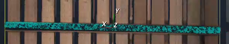
| Camera coordinate system | The origin of the coordinate system is above the object, and the positive Z-axis points downward; the XYZ values are the values of the object center point in this coordinate system | 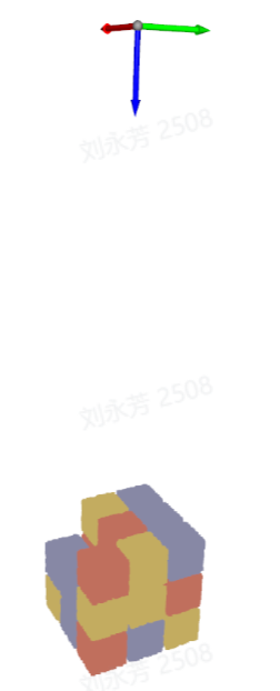 |
| ROI coordinate system | The origin of the coordinate system is approximately at the center of the stack, and the positive Z-axis points upward; the XYZ values are the values of the object center point in this coordinate system | 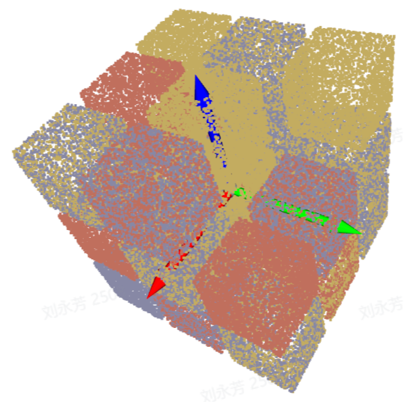 |
| Robot coordinate system | The origin of the coordinate system is on the robot itself, and the positive Z-axis generally points upward; the XYZ values are the values of the object center point in this coordinate system | 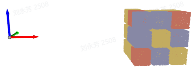 |
| Pixel coordinate system | The origin of the coordinate system is the upper-left vertex of the RGB image, which is a two-dimensional plane coordinate system; the X and Y values are the x value and y value of the bbox detection box, and Z is 0 |  |
1.5.2 General Picking Strategy
- Parameter Description
| Parameter | Description | Default Value |
|---|---|---|
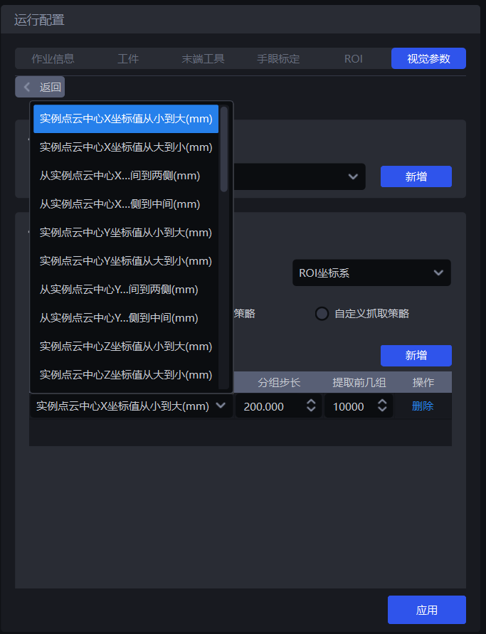
| Strategy | Select which value to use for grouping and sorting and how to sort, including multiple stackable criteria such as the XYZ coordinate values of the instance Point Cloud center, bounding box aspect ratio, and the distance from the instance Point Cloud center to the ROI center, which are executed in sequence | Instance Point Cloud center X coordinate value from small to large (mm) |
| Grouping step size | According to the selected strategy, instances are divided into several groups based on the step size. The grouping step size is the interval between two groups. For example, if the strategy selected is “Instance Point Cloud center Z coordinate value from large to small (mm)”, then the Z coordinates of all instance Point Cloud centers are sorted from large to small, and then grouped by the step size, and the corresponding instances are also divided into several groups | / |
| Extract the first several groups | After grouping and sorting, how many groups of instances need to be retained | 10000 |
| Strategy name* | Description | Grouping step size | Extract the first several groups | |
|---|---|---|---|---|
| Default Value | Value Range | Default Value | ||
| Instance Point Cloud center XYZ coordinate value from large to small / from small to large (mm) | Use the XYZ coordinate values of each instance's Point Cloud center for grouping and sorting Before using this strategy for sorting, the reference coordinate system should be set first | 200.000 | (0, 10000000] | 10000 |
| From the middle of the instance Point Cloud center XY coordinate axis to both sides / from both sides of the instance Point Cloud center XY coordinate axis to the middle (mm) | Use the XY coordinate values of each instance's Point Cloud center and group/sort in the direction of “middle to both sides” or “both sides to middle” Before using this strategy for sorting, the reference coordinate system should be set first | 200.000 | (0, 10000000] | 10000 |
| Bounding box center XY coordinate value from large to small / from small to large (mm) | Use the XY coordinate values of the center point of each instance's bounding box in the pixel coordinate system for grouping and sorting | 200.000 | (0, 10000000] | 10000 |
| Bounding box aspect ratio from large to small / from small to large | Use the ratio of the long side / short side of the bounding box for grouping and sorting | 1 | (0, 10000] | 10000 |
| From the middle of the bounding box center XY coordinate axis to both sides / from both sides to the middle (mm) | Use the XY coordinate values of the center point of the bounding box and group/sort in the direction of “middle to both sides” or “both sides to middle” | 200.000 | (0, 10000000] | 10000 |
| Target Object type ID from large to small / from small to large | Use the ID of the Target Object type for grouping and sorting, suitable for multi-class Target Object scenarios | 1 | [1, 10000] | 10000 |
| Local feature ID from large to small / from small to large | Use the ID of the local feature for grouping and sorting | 1 | [1, 10000] | 10000 |
| Confidence from large to small / from small to large | Use the Confidence of each instance for grouping and sorting | 1 | (0, 1] | 10000 |
| Visibility from small to large / from large to small | Use the visibility of each instance for grouping and sorting | 1 | (0, 0.1] | 10000 |
| Mask area from large to small / from small to large | Use the Mask area of each instance for grouping and sorting | 10000 | [1, 10000000] | 10000 |
| Distance from instance Point Cloud center to ROI center from near to far / from far to near (mm) | Use the distance between each instance's Point Cloud center and the center of the ROI coordinate system for grouping and sorting | 200.000 | (0, 10000000] | 10000 |
| Distance from instance Point Cloud center to robot coordinate origin from near to far / from far to near (mm) | Use the distance between each instance's Point Cloud center and the origin of the robot coordinate system for grouping and sorting | 200.000 | (0, 10000000] | 10000 |
- Example
1.5.3 Custom Picking Strategy
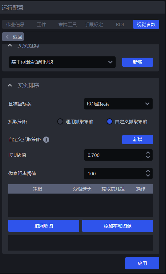
(1) Function Description
Switch Picking Strategy to Custom Picking Strategy, and click Add to add a custom picking strategy.
Customize the picking order of each Target Object. If the general picking strategy is difficult to use for picking, or it is difficult to tune proper Parameters because of Point Cloud noise and other issues, you can consider using a custom picking strategy.
The custom picking strategy is suitable for depalletizing scenarios and ordered loading/unloading scenarios, but not for random picking scenarios, because the Target Objects for a custom picking strategy must be ordered (that is, the order of Target Objects is fixed).
The custom picking strategy can only be combined with a single general picking strategy, and the strategy can only be selected as Z coordinate from small to large.
(2) Parameter Description
| Parameter | Description | Default Value | Value Range | Parameter Tuning |
|---|---|---|---|---|
| IOU Threshold | Represents the overlap Threshold between the annotated bbox and the detected bbox, and determines which image's sorting method should be selected for sorting the current Target Object instance through the overlap degree. | 0.7 | [0,1] | The larger the Threshold, the stricter the matching, and the worse the anti-interference ability. Minor changes in shape or position may cause matching failure, possibly matching the wrong custom strategy and sorting in the wrong order |
| Pixel distance Threshold | Represents the size difference between the bbox that can be matched and the detected bbox. | 100 | [0,1000] | The smaller the Threshold, the stricter the matching and the better the anti-interference ability. If the placement of Target Objects between different layers is similar, the custom strategy may also be mismatched, causing an incorrect sorting order. |
(3) Select the Reference Coordinate System
When using a custom picking strategy, only the camera coordinate system or pixel coordinate system can be selected
If there are multiple layers of Target Objects, select the camera coordinate system; if there is only one layer of Target Objects, select the pixel coordinate system.
(4) Strategy, Grouping Step Size, Extract the First Several Groups
| Parameter | Description | Default Value |
|---|---|---|
| Strategy | Only Instance Point Cloud center Z coordinate value from large to small / from small to large (mm) can be selected | / |
| Grouping step size | Based on the Z coordinate from small to large strategy, sort the Z coordinates of instances from small to large and divide the instances into several groups according to the step size | 10000 |
| Extract the first several groups | After grouping and sorting, how many groups of instances need to be retained | 10000 |
(5) Capture image / Add local image
Click Capture image to obtain an image from the currently connected camera, or click Add local image to import an image locally. However many layers there are, or however many different placement forms of Target Objects there are, that many images need to be captured or imported. If every layer is the same, only one image is needed. Right-click the image with the mouse to delete it.
On the obtained image, press and hold the left mouse button and drag to annotate a bbox. The DELETE key can delete annotated bbox boxes step by step.
2. 3D Calculation
2.1 Preprocessing
The preprocessing of 3D Calculation processes the 3D Point Cloud before the Deep Learning model performs computation.
2.1.1 Point Cloud Clustering Denoising
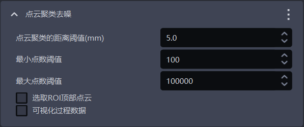
- Function
Remove noise by Point Cloud clustering.
- Usage Scenario
There is much noise in the instance Point Cloud.
- Parameter Description
| Parameter Name | Description | Default Value | Value Range | Unit | Parameter Tuning Suggestion |
|---|---|---|---|---|---|
| Distance Threshold for Point Cloud clustering (mm) | Determine whether Point Clouds in space belong to the same category. If the distance between Point Clouds is lower than this Threshold, they belong to the same category | 5 | [0.1, 1000] | mm | Generally does not need to be changed; it should be greater than the point spacing of the Target Object Point Cloud and smaller than the minimum distance between the Target Object Point Cloud and the noise Point Cloud |
| Minimum point count Threshold | Point Cloud clusters with fewer points than this count will be filtered out | 100 | [1,10000000] | / | Generally does not need to be changed; increase the minimum point count Threshold according to the size of noise in the instance Point Cloud |
| Maximum point count Threshold | Point Cloud clusters with more points than this count will be filtered out | 100000 | [1,10000000] | / | Generally does not need to be changed; if the Target Object Point Cloud count is greater than 100000, increase the maximum point count Threshold |
| Select top ROI Point Cloud | Checked means calculate and sort the average Z coordinate values of Point Clouds of the same category in the ROI coordinate system, and retain the Point Cloud category with the largest average Z coordinate value (top Point Cloud); unchecked means retain all Point Clouds that meet the conditions | Unchecked | / | / | If the Target Object Point Cloud is above the noise Point Cloud, checking this will retain the Target Object Point Cloud; if the Target Object Point Cloud is below the noise Point Cloud, you should check this option and also adjust the Z-axis of the ROI coordinate system downward in order to retain the Target Object Point Cloud |
| Visualize process data | Checked means save the denoised Point Cloud, which can be viewed in C:_data | Unchecked | / | / | In debug mode, if visualized data needs to be saved, this can be checked |
- Example
2.1.2 Point Cloud Downsampling
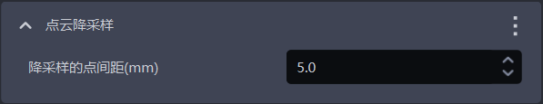
- Function
Sample the Point Cloud according to the specified point spacing during downsampling.
- Usage Scenario
Check this when the camera precision is high and causes the instance Point Cloud count to be too large, and the log reports "The number of instance Point Clouds input for pose estimation exceeds the PMFE algorithm limit".
- Parameter Description
| Parameter | Description | Default Value | Parameter Range | Unit |
|---|---|---|---|---|
| Downsampling point spacing (mm) | Sample the Point Cloud according to the specified point spacing | 5 | [0.1, 1000] | mm |
Parameter Tuning
- Set according to the point spacing of the instance Point Cloud. The larger the value, the fewer Point Cloud points after downsampling
2.1.3 Calculate Normal Vectors
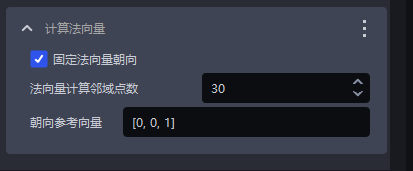
- Function
Calculate Point Cloud normal vectors for subsequent Point Cloud processing.
- Parameter Description
| Parameter Name | Description | Default Value | Value Range |
|---|---|---|---|
| Fix normal vector orientation | Whether to fix the orientation when calculating normal vectors. After enabling, the normal vector is determined by the orientation reference vector | Checked | / |
| Neighbor point count for normal vector calculation | The larger the value, the more neighboring points are referenced, but local variations may be ignored; the smaller the value, the opposite applies | 30 | [1,200] |
| Orientation reference vector | Reference vector for normal vector calculation orientation | [0,0,1] | / |
- Parameter Tuning
Cannot be changed
2.1.4 Point Cloud Contour Extraction
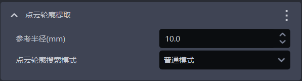
- Function
Extract the contour of the Target Object from the instance Point Cloud.
- Usage Scenario
When using 2.2.4 Enable contour mode, Point Cloud contour extraction should also be checked.
- Parameter Description
| Parameter Name | Description | Default Value | Value Range | Unit | Parameter Tuning Suggestion |
|---|---|---|---|---|---|
| Reference radius (mm) | The search radius for extracting the contour from the instance Point Cloud | 10 | [0.1,10000000000] | mm | The reference radius is recommended to be set to 1/2 of the downsampling point spacing in 2.1.2 Point Cloud Downsampling, and it must be greater than the Point Cloud spacing |
| Point Cloud contour search mode | The mode for searching the Point Cloud contour | Normal mode | Normal mode; Plane mode | Generally select normal mode; for planar Target Objects, select plane mode |
- Example
2.1.5 Filter Point Cloud by HSV color range (hue, saturation, brightness)
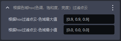
Function
Filter the Point Cloud according to hue, saturation, and brightness in the Point Cloud image, and screen out Point Cloud regions matching the target range
Parameter Description
| Parameter Name | Description | Default Value | Value Range |
|---|---|---|---|
| Filter depth by HSV - maximum color range value | Maximum color value for filtering the Point Cloud | [0.9,0.9,0.9] | [[0,0,0],[1,1,1]] |
| Filter depth by HSV - minimum color range value | Minimum color value for filtering the Point Cloud | [0.0,0.0,0.0] | [[0,0,0],[1,1,1]] |
Example
2.1.6 Filter Point Cloud by Three-Channel Color
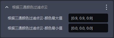
- Function
Filter the Point Cloud according to three-channel color and screen out Point Cloud regions matching the target range.
- Parameter Description
| Parameter Name | Description | Default Value | Value Range |
|---|---|---|---|
| Filter Point Cloud by three-channel color - maximum color value | Maximum color value for filtering the Point Cloud | [0.9,0.9,0.9] | [[0,0,0],[1,1,1]] |
| Filter depth by three-channel color - minimum color value | Minimum color value for filtering the Point Cloud | [0.0,0.0,0.0] | [[0,0,0],[1,1,1]] |
- Example
2.1.7 Select Point Cloud within the ROI region
- Function
Select the Point Cloud within the ROI 3D region from the instance Point Cloud. This default function cannot be deleted.
- Example
2.1.8 Remove Points Whose Normals Exceed the Angle Threshold
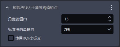
- Function
Remove Point Cloud points whose angle between the normal vector and the axis direction of the standard normal vector is greater than the normal vector angle Threshold.
- Usage Scenario
Circular-surface-based random picking, circular-surface-based ordered loading/unloading.
- Parameter Description
| Parameter Name | Description | Default Value | Value Range | Unit |
|---|---|---|---|---|
| Angle Threshold | Point Clouds greater than this angle Threshold are considered different instances | 15 | [-360, 360] | / |
| Standard normal vector axis direction | The angle formed between the normal vector of the Point Cloud and the axis direction of the standard normal vector | Z-axis | X/Y/Z-axis | / |
| Whether to use ROI coordinate system | Checked means calculate the angle between the normal vector and the axes of the ROI coordinate system; unchecked means calculate the angle between the normal vector and the axes of the camera coordinate system | Unchecked | / | / |
- Parameter Tuning
2.1.9 Point Cloud Plane Segmentation
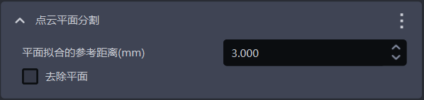
- Function
Retain or remove the plane with the largest number of Point Cloud points in the instance Point Cloud.
- Usage Scenario
The instance Point Cloud contains a noisy plane.
- Parameter Description
| Parameter | Description | Default Value | Value Range | Unit | Parameter Tuning Suggestion |
|---|---|---|---|---|---|
| Reference distance for plane fitting (mm) | If the distance from a point to the plane is less than the reference distance, it is considered a point on the plane; otherwise, it is considered a point outside the plane | 3 | [0.001,10000] | mm | Generally unchanged |
| Remove plane | Checked means remove the plane with the largest number of Point Cloud points; unchecked means retain the plane with the largest number of Point Cloud points | Unchecked | / | / | If the plane with the largest number of Point Cloud points is the Target Object, retain the plane and leave unchecked; if the plane with the largest number of Point Cloud points is noise, remove the plane and check this option |
- Example
2.1.10 Remove outlier points from Point Cloud
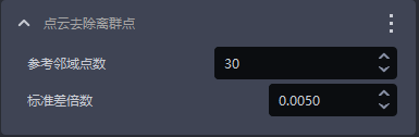
- Function
Identify and remove outlier noise in the Point Cloud to improve Point Cloud quality.
- Usage Scenario
The instance Point Cloud contains many outlier noise points.
- Parameter Description
| Parameter Name | Description | Default Value | Value Range |
|---|---|---|---|
| Reference neighboring point count | The number of neighboring points around each point in the Point Cloud, that is, the neighborhood size. For dense Point Clouds, even a smaller neighborhood is sufficient to reflect the features of the Target Object, so a smaller value can be used; for sparser Point Clouds, a larger neighborhood is needed to reflect the features of the Target Object, so a larger value should be used. | 30 | [1, 10000000] |
| Standard deviation multiplier | Used to identify outlier noise. If the deviation of a point's coordinates from the average coordinates of the instance Point Cloud exceeds the standard deviation multiplier, the point is considered an outlier. The smaller the value, the more points are considered outliers and the more outliers are removed, but it may cause misjudgment and remove important features of the Target Object; the larger the value, the fewer points are considered outliers and the fewer outliers are removed, but some outliers may be retained and affect the accuracy of Target Object recognition. | 0.005 | [0.0001, 2] |
- Parameter Tuning
Generally unchanged. If the Point Cloud becomes too sparse after removing outlier points from Point Cloud, you should increase the standard deviation multiplier.
- Example
2.1.11 Filter Out Point Clouds Whose Object Distance Exceeds the Limit
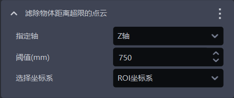
- Function
Filter out Point Clouds in the specified direction, remove noise points, and improve image recognition accuracy.
- Parameter Description
| Parameter | Description | Default Value | Parameter Range | Unit | Parameter Tuning Suggestion |
|---|---|---|---|---|---|
| Specified axis | The specified axis of the Point Cloud, used to filter out Point Clouds in the specified direction | Z-axis | X/Y/Z-axis | / | Specified axis generally does not need to be changed |
| Threshold (mm) | In the specified axis direction, if the distance between the lower-layer Point Cloud and the Target Object Point Cloud is greater than this Threshold, the lower-layer Point Cloud will be filtered out; if the distance between the lower-layer Point Cloud and the Target Object Point Cloud is less than this Threshold, the lower-layer Point Cloud will be retained | 750 | [0, 1000] | mm | Adjust the Threshold according to the actual scenario. The larger the Threshold, the fewer Point Clouds are filtered out; the smaller the Threshold, the more Point Clouds are filtered out |
| Select coordinate system | Filter out Point Clouds in the selected coordinate system | ROI coordinate system | Camera coordinate system; ROI coordinate system; object self coordinate system | / |
- Example
2.1.12 Optimize Mask According to Point Cloud
- Function
Based on the Point Cloud within ROI 3D, remove Point Cloud points in the Mask that are not within ROI 3D, improving the accuracy of the Mask.
2.2 Basic Shape Pose Estimation
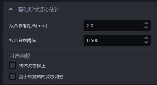
2.2.1 Fitting Reference Distance (mm)
- Function
The model calculates an ideal circle according to the instance Point Cloud, and Point Cloud points whose distance to the ideal circle is less than the fitting reference distance are fitted into a ring.
- Usage Scenario
Circular-surface-based ordered loading/unloading, circular-surface-based random picking scenarios.
- Parameter Description
Default value: 2
Value range: [0.1, 1000]
Unit: mm
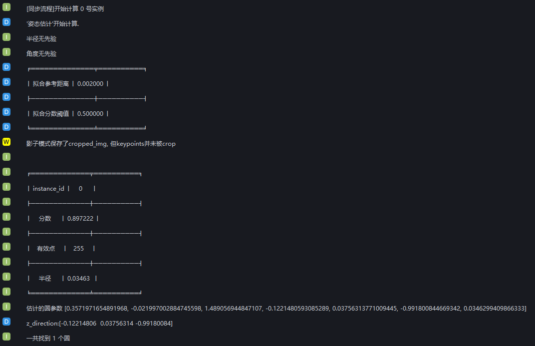
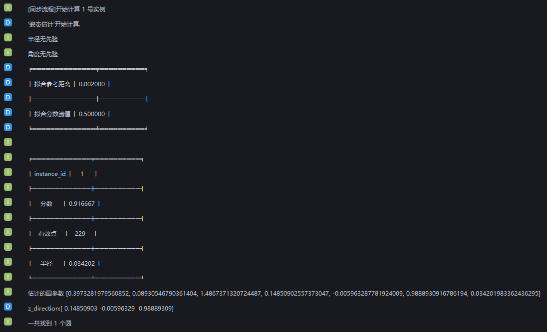
Parameter Tuning
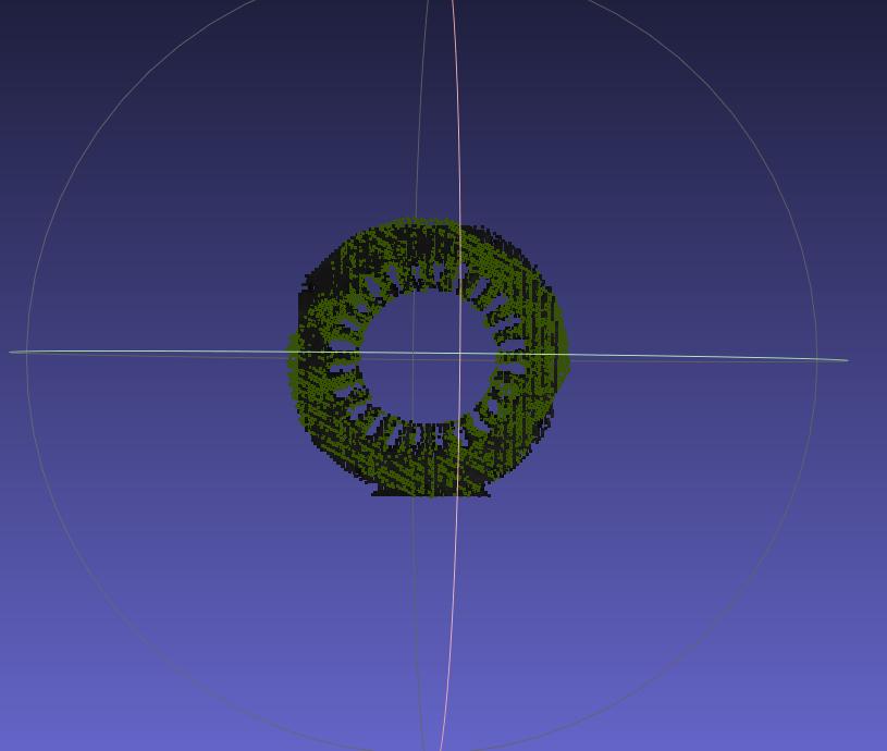
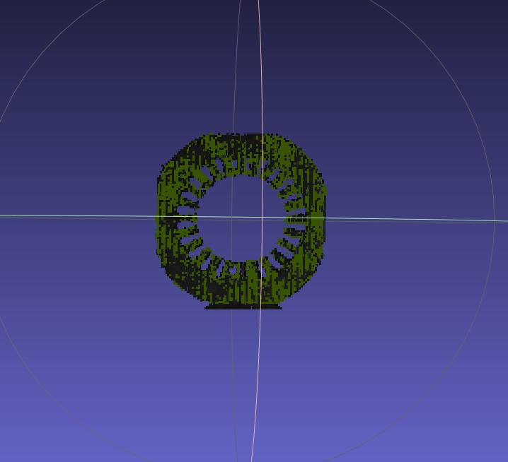
- The log for fitting the circular surface is shown below
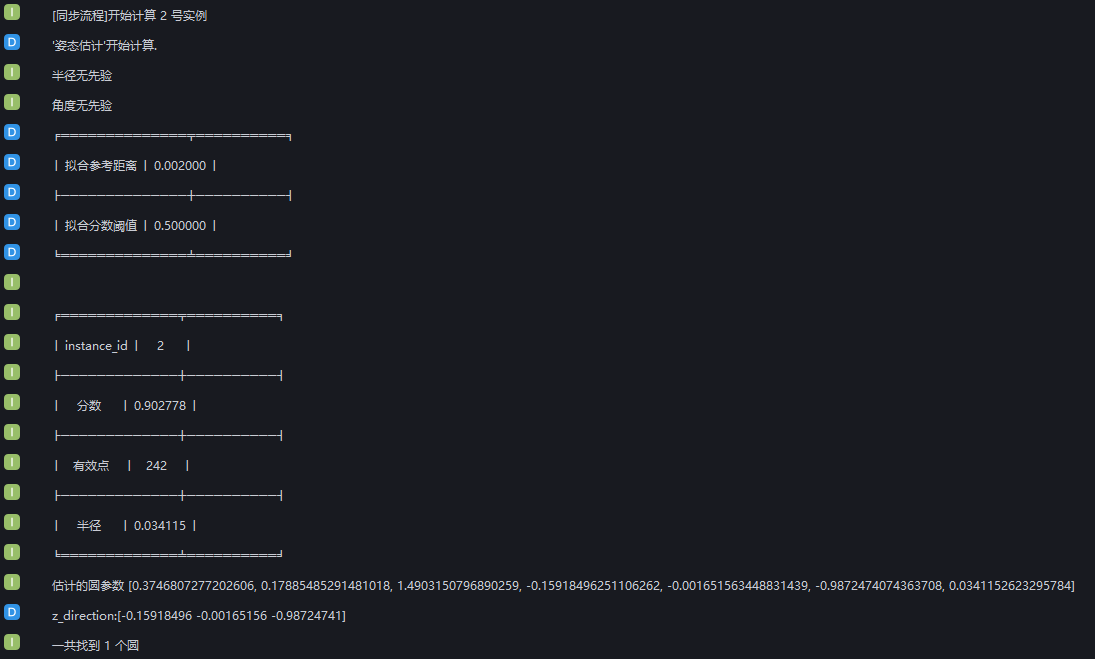
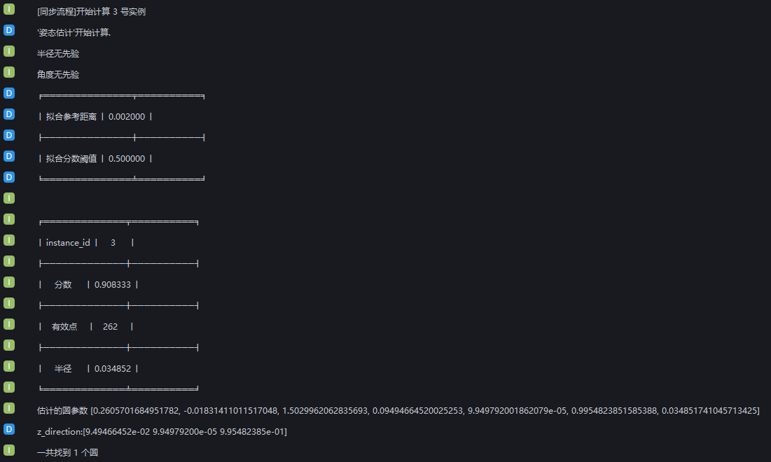
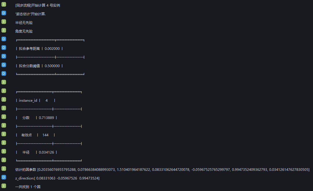
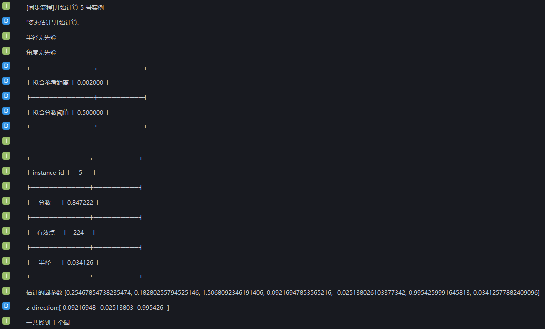
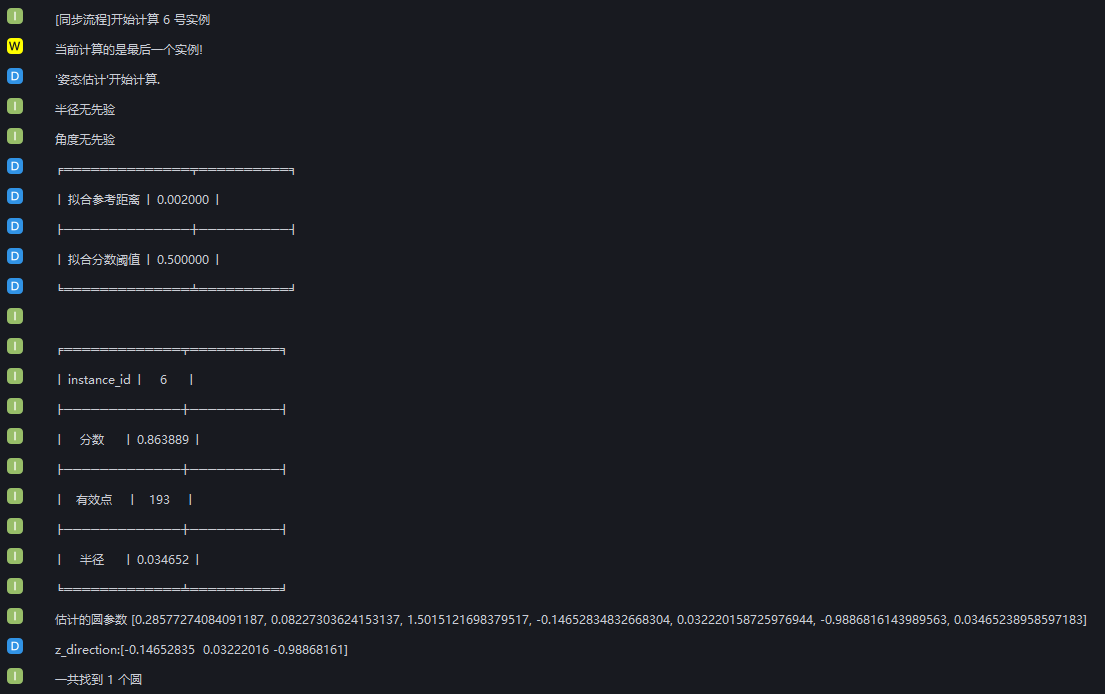
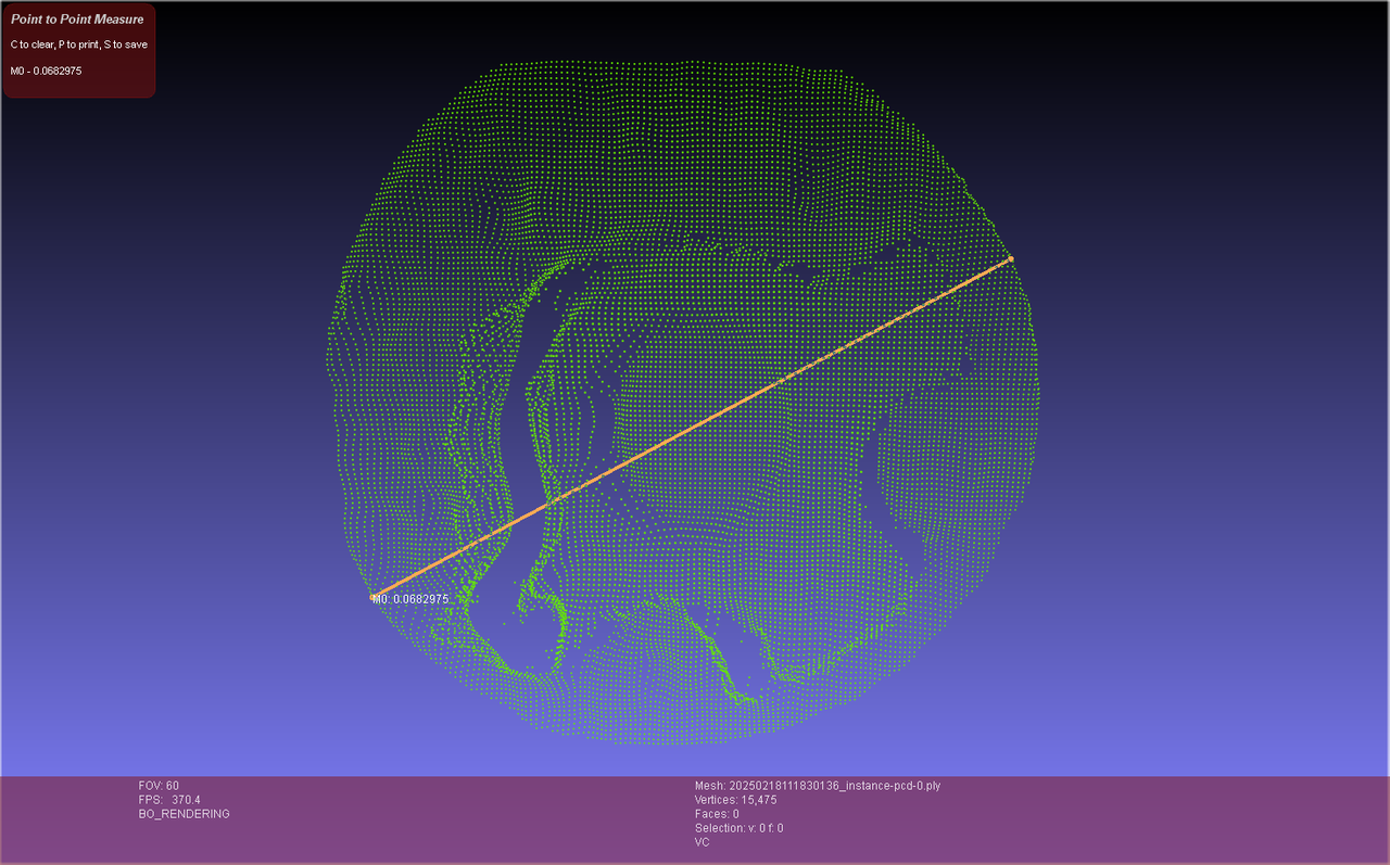
You can view the circular-surface fitting result in the visualization window, as shown below.
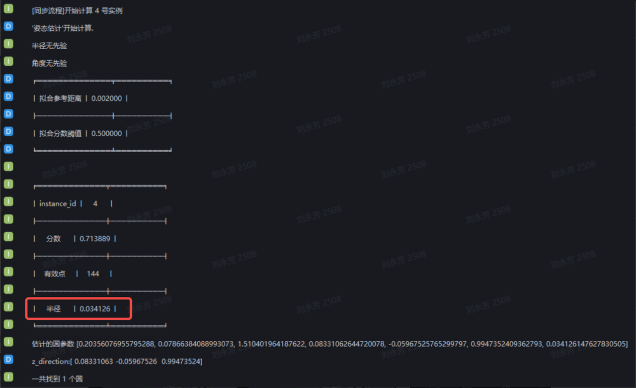
- If the Pick Point deviates from the circle center, you should pre-enter the radius of the circular-surface Target Object in the Target Object interface before running
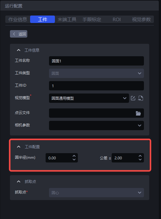
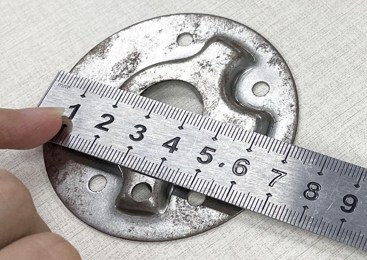
You can obtain the radius of the Target Object from the log, or measure the diameter of the Target Object to get the radius. If there is no Target Object, you can also measure the diameter of the instance Point Cloud to get the radius.
After adding the radius prior, the generated Pick Point is more biased toward the circle center, and the fitted circular surface matches the ideal circle better.
- If the log reports "The x-th circle was not found", it means the circular surface cannot be fitted. You should increase the fitting reference distance so that more Point Cloud points are included in fitting the circular surface. If the value is too large, noise points may be included.
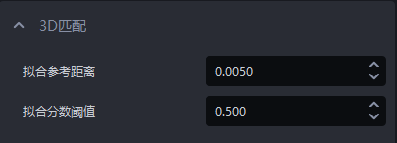
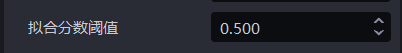
2.2.2 Fitting score Threshold
- Function
Calculate the ratio between the number of Point Cloud points on the fitted circular surface and the number of Point Cloud points on the ideal circular surface. Fitted circular surfaces whose ratio is lower than the fitting score Threshold will be filtered out.
- Usage Scenario
Circular-surface-based ordered loading/unloading, circular-surface-based random picking.
- Parameter Description
Default value: 0.5
Value range: [0,1]
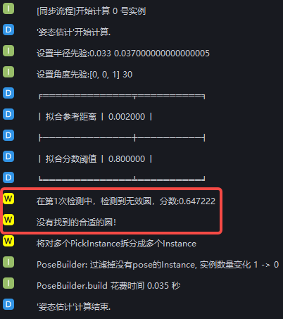
- Parameter Tuning
If the log reports "Invalid circle detected" as shown below, you should reduce the fitting score Threshold according to the score in the log.
- Example
2.2.3 Object Pose Correction
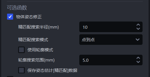
- Function
Optimize the circular-surface fitting result.
- Usage Scenario
The picking pose is not accurate.
- Parameter Description
| Parameter Name | Description | Default Value | Value Range | Unit |
|---|---|---|---|---|
| Fine matching search radius (mm) | During fine matching, the template Point Cloud is matched with the instance Point Cloud, and each point in the template Point Cloud needs to search for the nearest point in the instance Point Cloud. The fine matching search radius represents both the search radius in the instance Point Cloud and the distance Threshold between each point in the template Point Cloud and the nearest point in the instance Point Cloud. If the distance between a point and its nearest point is less than the fine matching search radius, the two points are considered matchable; otherwise, they are considered unmatchable. | 10 | [1, 500] | mm |
| Fine matching search mode | The way the template Point Cloud retrieves the nearest point in the instance Point Cloud during fine matching | Point-to-point | Point-to-point, point-to-plane, combination of point-to-point and point-to-plane | / |
| Template Point Cloud file Path | Upload the template Point Cloud file of the Target Object for fine matching. It should be in C:_pcd文件 | / | / | / |
| Use contour mode | Extract contour Point Clouds from the template Point Cloud and the instance Point Cloud for coarse matching | Unchecked | / | / |
| Contour search range (mm) | The search radius for extracting contour Point Clouds from the template Point Cloud and the instance Point Cloud | 5 | [0.1, 500] | mm |
| Whether to save pose estimation [fine matching] data | Checked means save fine matching data to C: | Unchecked | / | / |
Parameter Tuning
If the output picking pose does not meet the accuracy requirement, check Object Pose Correction
Measure the diameter of the circular-surface Target Object. If the diameter is small, reduce the fine matching search radius
If the circular-surface Target Object is a pure plane, use point-to-plane for fine matching search mode; if the circular-surface Target Object is not a pure plane, use the default point-to-point for fine matching search mode
Check the fine matching result. If the fine matching result is poor, check Use contour mode to extract contour Point Clouds from the template Point Cloud and the instance Point Cloud for matching
Fine Matching Search Radius (mm)

- Function
During fine matching, the template Point Cloud is matched with the instance Point Cloud, and each point in the template Point Cloud needs to search for the nearest point in the instance Point Cloud. The fine matching search radius represents both the search radius in the instance Point Cloud and the distance Threshold between each point in the template Point Cloud and the nearest point in the instance Point Cloud. If the distance between a point and its nearest point is less than the fine matching search radius, the two points are considered matchable; otherwise, they are considered unmatchable.
- Usage Scenario
Planar Target Object ordered loading/unloading, planar Target Object random picking, planar Target Object positioning and assembly scenarios.
- Parameter Description
Default value: 10
Value range: [1, 500]
Unit: mm
- Parameter Tuning
Usually unchanged
Fine Matching Search Mode

- Function
The way the template Point Cloud retrieves the nearest point in the instance Point Cloud during fine matching.
- Usage Scenario
If the fine matching effect between the template Point Cloud and the instance Point Cloud is poor, this function should be adjusted.
- Parameter Description
| Parameter | Description |
|---|---|
| Point-to-point | Each point in the template Point Cloud searches for the nearest point in the instance Point Cloud (the point with the shortest straight-line distance within the search radius). Suitable for all Target Objects |
| Point-to-plane | Each point in the template Point Cloud searches for the nearest point in the instance Point Cloud along its normal vector. Suitable for Target Objects with obvious geometric features |
| Combination of point-to-point and point-to-plane | First use the point-to-point mode to optimize the Target Object pose in the instance Point Cloud, then use the point-to-plane mode to optimize the Target Object pose in the instance Point Cloud. Suitable for Target Objects with obvious geometric features
|
Use Contour Mode
- Function
Extract contour Point Clouds from the template Point Cloud and the instance Point Cloud for coarse matching.
- Usage Scenario
In planar Target Object ordered loading/unloading, planar Target Object random picking, and planar Target Object positioning and assembly scenarios, if the result of coarse matching using key points is poor, this function should be checked to use contour Point Clouds for coarse matching again.
- Parameter Tuning
The coarse matching result affects the fine matching result. If the fine matching result is poor, you can check Use Contour Mode
Contour Search Range (mm)

- Function
The search radius for extracting contour Point Clouds from the template Point Cloud and the instance Point Cloud.
- Usage Scenario
General Target Object ordered loading/unloading, general Target Object random picking, general Target Object positioning and assembly scenarios.
- Parameter Description
Default value: 5
Value range: [0.1, 500]
Unit: mm
- Parameter Tuning
If the value is small, the radius for searching contour Point Clouds is small, which is suitable for extracting fine Target Object contours, but the extracted contours may contain outlier noise;
If the value is large, the radius for searching contour Point Clouds is large, which is suitable for extracting broader Target Object contours, but the extracted contours may ignore some detailed features.
Save Pose Estimation [Fine Matching] Data
- Function
Checked means save fine matching data.
- Usage Scenario
Planar Target Object ordered loading/unloading, planar Target Object random picking, planar Target Object positioning and assembly, planar Target Object positioning and assembly (matching only)
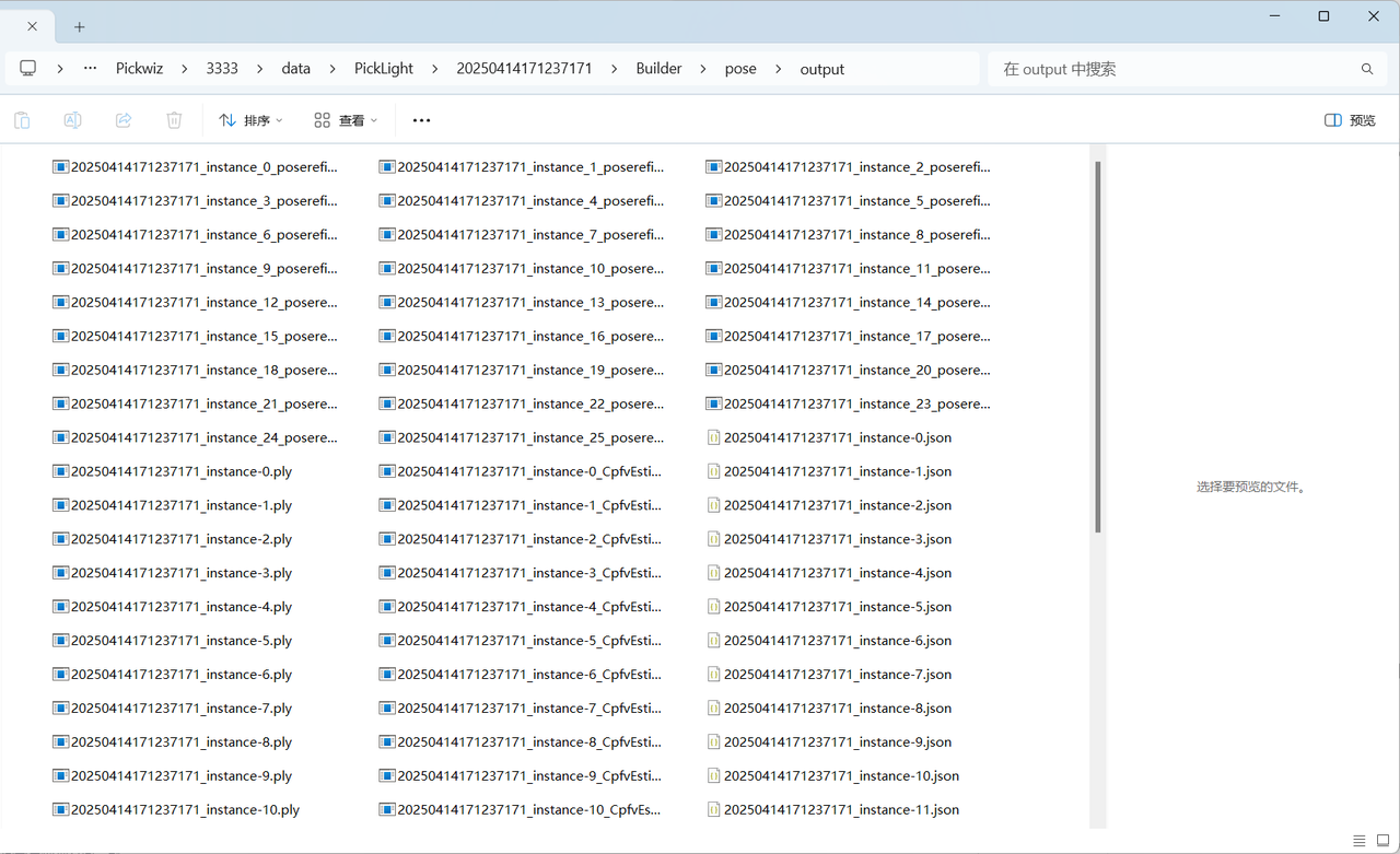
- Example
The fine matching data is saved in the \ProjectFolder\data\PickLight\HistoricalDataTimestamp\Builder\pose\output folder under the project save Path.
2.2.4 Axis-Rotation-Based Pose Adjustment
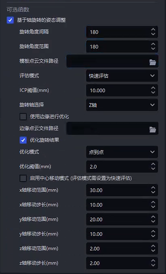
- Function
Rotate and translate the instance Point Cloud around the given axis based on the first Pick Point of the Target Object, calculate the matching score between the instance Point Cloud and the template Point Cloud after each rotation and translation, and select the instance Point Cloud with the highest matching score as the final pose of the rotationally symmetric Target Object.
- Usage Scenario
Deviation occurs when matching the instance Point Cloud and the template Point Cloud of a rotationally symmetric Target Object, and a certain angle of rotation is required for a complete match.
Cannot be used together with the recognition type, front/back recognition (via Point Cloud template), or local feature recognition in the function options
- Parameter Description
| Parameter | Description | Default Value | Parameter Range | Parameter Tuning Suggestion |
|---|---|---|---|---|
| Rotation angle interval | Rotate the instance Point Cloud at equal angle intervals. The angle difference between two adjacent rotations. For example, if the first rotation is 30°, the second is 60°, and the third is 90°, then the rotation angle interval is 30°. | 5 | \[1, 180\] | If the Target Object has many features and matching is difficult and high-precision matching is desired, a smaller angle interval can be set to perform more matches, but the computation will increase. If the Target Object has a simple shape with fewer features, a larger angle interval can be set to improve computational efficiency. |
| Rotation angle range | The maximum angle range through which the instance Point Cloud can rotate from its initial state. | 90 | \[1, 180\] |
|
| Template Point Cloud file Path | Upload the template Point Cloud file of the Target Object. If not uploaded, the Point Cloud template uploaded in the Target Object interface will be used | / | / | |
| Evaluation mode | Evaluate the quality of matching results from different perspectives | Iso-target | Iso-target;Iso-source;Average;Strict;Loose;Fast |
|
| ICP Threshold | The criterion for judging whether registration is successful. If the matching result error is less than this Threshold, the match is successful; if the matching result error is greater than this Threshold, the match is unsuccessful | 0.005 | \[0.000001, 1\] | Generally unchanged. If the actual scenario requires high matching accuracy, reduce this Threshold; if the actual scenario requires high matching speed and lower accuracy, increase this Threshold. If the Target Object Point Cloud quality is good, reduce this Threshold; if the Target Object Point Cloud quality is poor, increase this Threshold. |
| Rotation axis selection | The instance Point Cloud rotates around this axis | Z-axis | X/Y/Z-axis | Generally unchanged. If a certain axis of the rotationally symmetric Target Object is important for recognizing the Target Object pose, the rotation axis can be set to that feature axis |
| Save visualization data | Whether to save visualization data | Unchecked | / | |
| Use edges for optimization | Use the edge contour of the Target Object to optimize matching, reduce matching result errors, and make the matching between the instance Point Cloud and the template Point Cloud more precise | Unchecked | / | If the edge contour of the Target Object has unique geometric features, checking this function can improve matching accuracy. For example, for Target Objects with complex shapes and large differences in edge contours, using the edge contour Point Cloud can identify the Target Object pose more accurately. |
| Edge Point Cloud file Path | Upload the edge Point Cloud file of the Target Object. If not uploaded, the edge Point Cloud will be extracted from the Point Cloud template uploaded in the Target Object interface | / | / | |
| Optimize rotation result | After the best pose is found during matching, optimize it again to reduce matching result errors and make the matching between the instance Point Cloud and the template Point Cloud more precise | Checked | / | Checked by default to improve matching accuracy; generally unchanged |
| Optimization mode | Mode for optimizing matching results | Point | Point;Plane;Full |
|
| Optimization Threshold | The criterion for judging whether registration has reached the expected accuracy during optimization. If the registration error is less than this Threshold, optimization is successful; if the registration error is greater than this Threshold, optimization fails and iteration needs to continue. | 0.002 | \[0.0001, 1\] | Generally unchanged. Reduce this Threshold for scenarios with higher registration accuracy requirements; increase this Threshold for scenarios with lower registration accuracy requirements. |
| Enable center movement mode | When enabled, translation mode is also added, stacking translation while rotating the instance Point Cloud | Unchecked |
| |
| x-axis movement range | The movement range of center movement mode along the Pick Point x-axis (mm) | 0 | \[0,100\] |
|
| x-axis movement step size | The movement step size of center movement mode along the Pick Point x-axis (mm) | 2 | \[0.01,10\] | The step size must be set reasonably according to the offset and accuracy. Setting the step size too small will significantly increase cycle time |
| y-axis movement range | The movement range of center movement mode along the Pick Point y-axis (mm) | 0 | \[0,100\] |
|
| y-axis movement step size | The movement step size of center movement mode along the Pick Point y-axis (mm) | 2 | \[0.01,10\] | The step size must be set reasonably according to the offset and accuracy. Setting the step size too small will significantly increase cycle time |
| z-axis movement range | The movement range of center movement mode along the Pick Point z-axis (mm) | 0 | \[0,100\] |
|
| z-axis movement step size | The movement step size of center movement mode along the Pick Point z-axis (mm) | 2 | \[0.01,10\] | The step size must be set reasonably according to the offset and accuracy. Setting the step size too small will significantly increase cycle time |
- Example
Axis matching offset
After adding center movement mode
- Description of the number of poses evaluated by axis-rotation-based pose adjustment
Total number of pose calculations = number of x-axis movement positions * number of y-axis movement positions * number of z -axis movement positions * number of angle positions
An excessively large movement range or too small a step size will increase the total number of poses that need to be evaluated and lengthen the cycle time. The range and step size Parameters must be set reasonably
2.3 Empty ROI Judgment
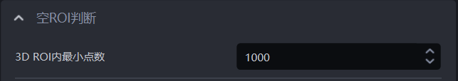
- Function
Determine whether there are still remaining Target Objects (Point Clouds) in ROI 3D. If the number of 3D points in ROI 3D is less than this value, it means there is no Target Object Point Cloud remaining, and no Point Cloud is returned at this time.
- Parameter Description
Default value: 1000
Value range: [0, 100000]
- Usage Process
Set the minimum 3D ROI point count judgment Threshold. If it is lower than this Threshold, the Target Object Point Cloud in ROI 3D is insufficient, so it is determined that there is no Target Object in ROI 3D;
In the robot configuration, add a new vision status code to facilitate subsequent robot signal processing.