Common Recognition and Picking Issues
1. Stereo Camera
Stereo Camera Windows PickWiz Deployment (Application)
1.1 Image Acquisition Takes Too Long with Automatic Exposure
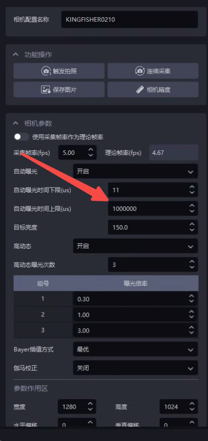
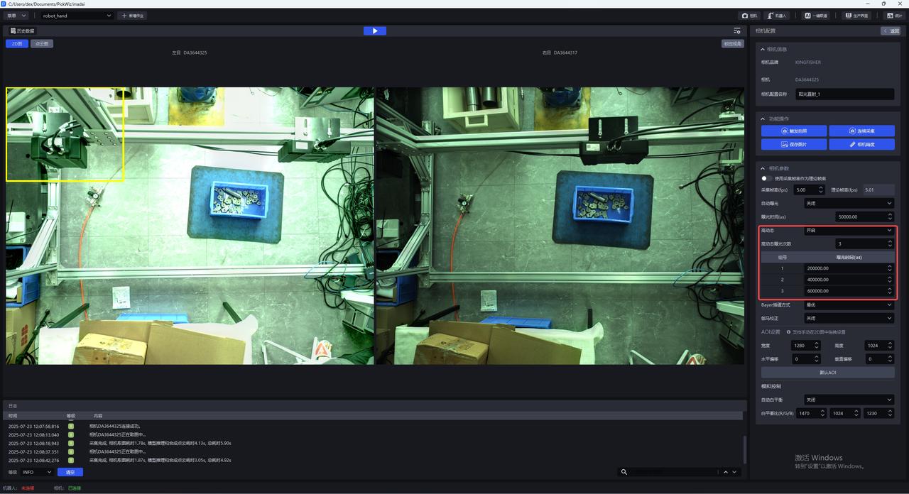
Issue: When using a stereo Camera, how can the image capture Takt Time be further optimized under auto exposure or multiplier-based HDR mode 【≥1.7.1】:
Solution: The upper limit of the auto exposure time can be used to control the maximum exposure time of a single image (it is recommended to set it greater than 200000μs, that is, 200ms. Setting it lower will not improve the frame rate either. The maximum frame rate is 5 frames, and it will instead damage image quality). 200000μs is already the fastest Takt Time. The algorithm will automatically compensate brightness according to the gain, so the overall effect remains unchanged, but the image capture time is reduced. Under HDR mode, this parameter can also be used to control the maximum exposure time, thereby reducing the overall HDR time.
1.2 Crash During Photo Capture
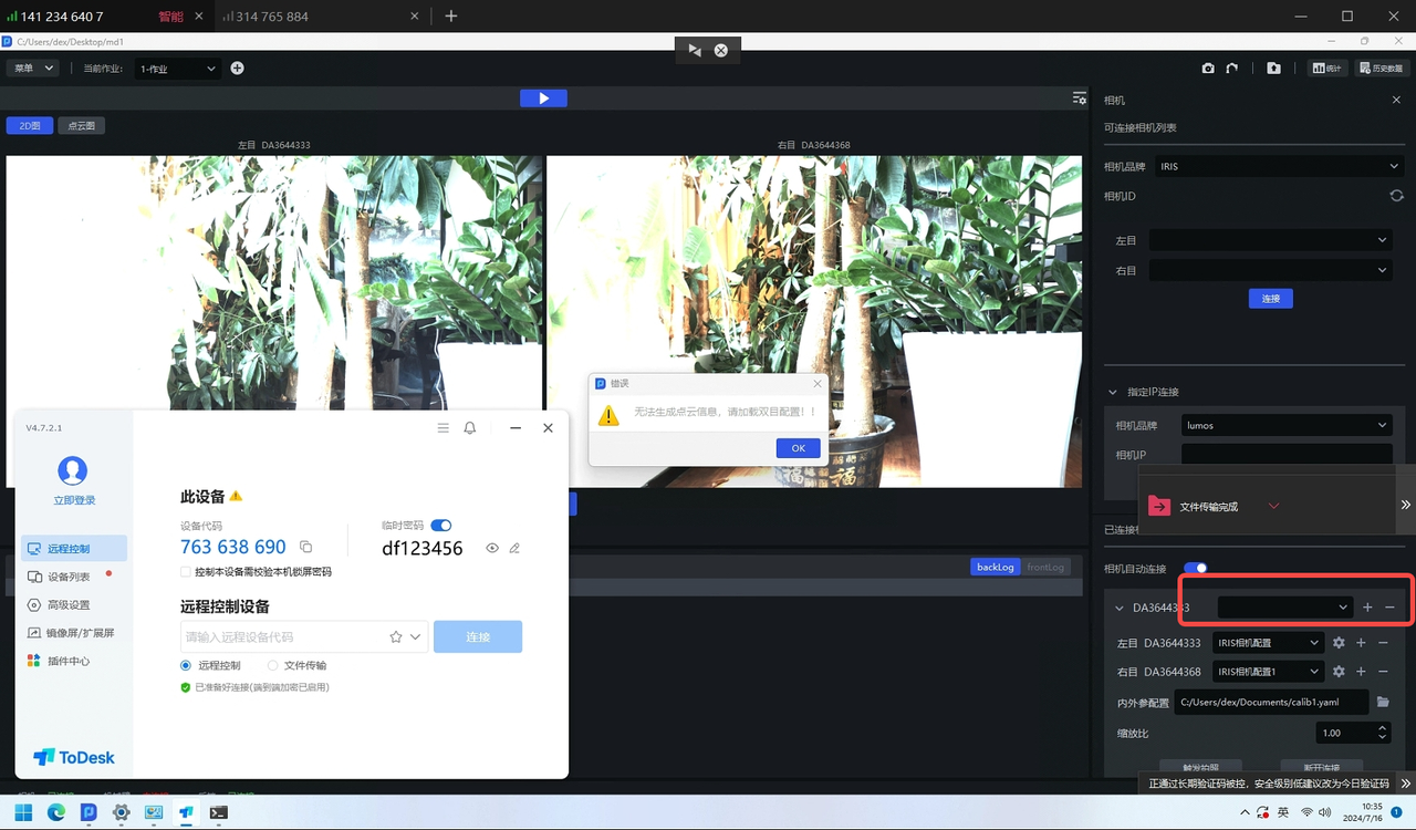
Issue: The software crashes when photographing with a stereo Camera
Possible cause: The stereo Camera is not using Gigabit Ethernet
Solution: The stereo Camera must use Gigabit Ethernet. First check whether the network cable supports Gigabit Ethernet. If not, replace it.
1.3 Image capture failed error
Issue: The stereo Camera reports an image capture failed error
Solution: Create a new stereo Camera configuration, and then capture the image again.
1.4 Image capture failed error
Issue: The stereo Camera reports an image capture failed error
Possible cause: Severe packet loss
Solution:
Use the MVS software to connect to the stereo Camera and start acquisition to check whether a pop-up indicates severe packet loss
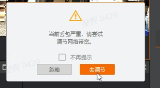
If yes
Ensure that the Camera switch is dedicated to Camera use to keep the network stable, and set the Camera exposure to 5000 to facilitate subsequent bandwidth testing;
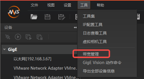
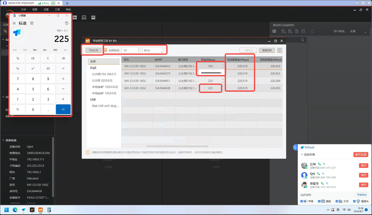
Open the bandwidth management tool and connect to the Camera you want to use;
Confirm the maximum network bandwidth: slide the Camera bandwidth to the maximum and confirm this maximum value, for example 964M. According to testing, part of the bandwidth (tentatively 64M) should be reserved as margin, so the total available bandwidth is 900M;
Allocate bandwidth according to the number of devices in use: for example, if 4 cameras need to be used at the same time, set the Camera bandwidth to 900/4=225M;
Click Start Analysis. If the bandwidth for (sent data volume) is not fully utilized or the Camera still experiences packet loss, continue locating the cause;
1.5 Abnormal Point Cloud
Issue: The Point Cloud imaging of the stereo Camera is collapsed / distorted
Possible cause: The 2D imaging is overexposed / too dark, the long side of the workpiece is not perpendicular to the image, and there is a visual blind spot
Solution:
- First check whether the 2D imaging is overexposed / too dark. If yes, adjust the exposure first.
| Status | 2D Image | Point Cloud | Remarks | Handling Method |
|---|---|---|---|---|
| Before exposure adjustment (too dark) |  |  | Collapsed | Add a light source so that the surface of the Target Object is clearly visible |
| After exposure adjustment |  | 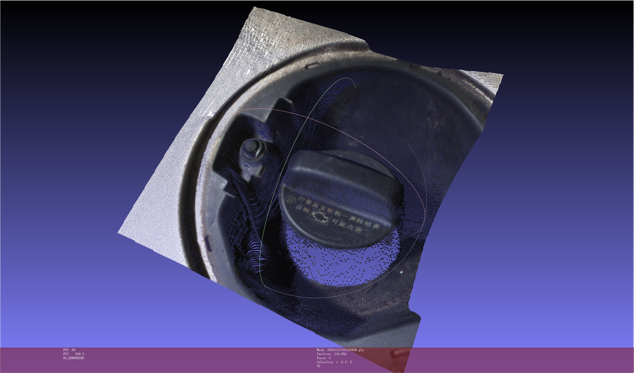 | Normal | / |
| Status | Point Cloud | Remarks | Handling Method |
|---|---|---|---|
| Before exposure adjustment (too dark) | 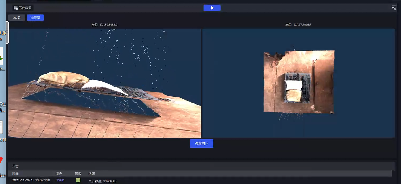 | Collapsed | 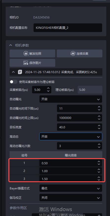 |
| After exposure adjustment | 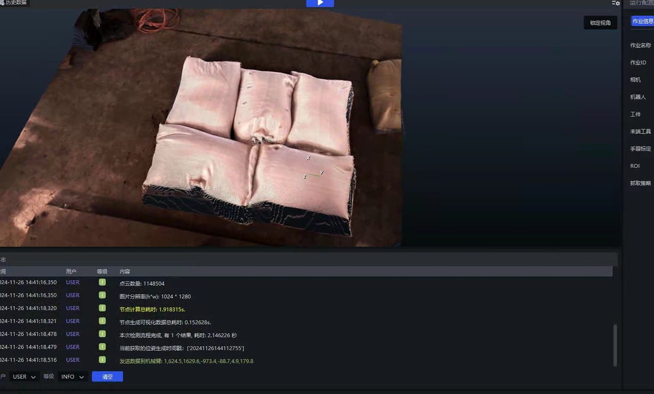 | Normal | / |
Check whether the long side of the workpiece is perpendicular to the image. This involves the stereo principle issue of "corresponding points". It is recommended to rotate the Camera installation angle by 90 degrees, as shown below.

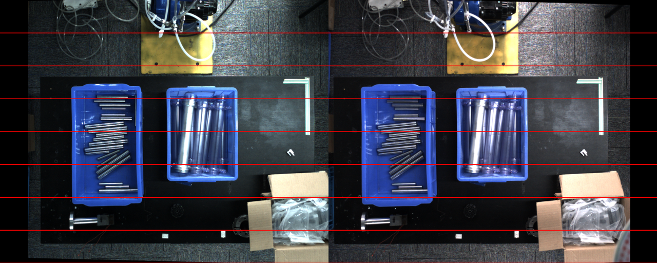
If the object has a "visual blind spot" in the left and right images, the model will not be able to correctly predict the Point Cloud, causing distortion or collapse
How should this visual blind spot be understood? Is it that only one Camera can capture it?: The left Camera can see it while the right Camera cannot (and vice versa)
Why "can't it be solved by the model"?: Usually, the way to solve this issue is Shadow mode, but this area happens to be an occluded area, and such an area will not enter Shadow mode learning. Therefore it is ineffective.Example Imaging 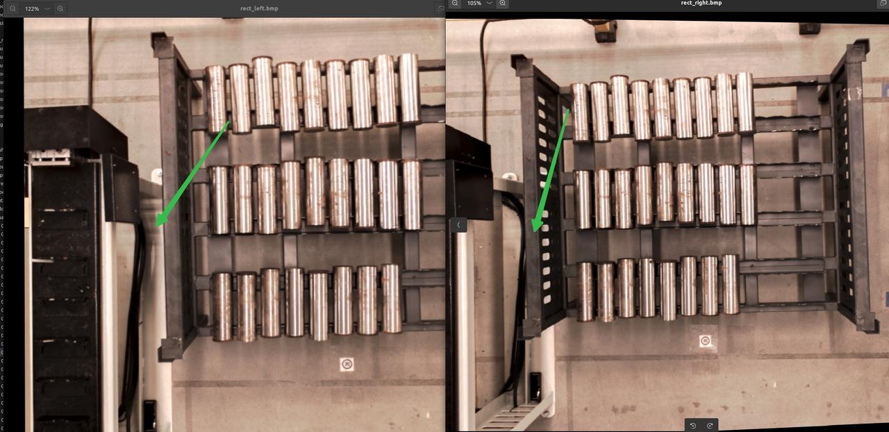
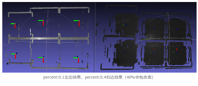
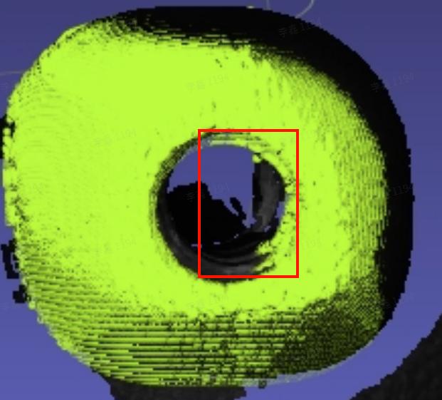
If the red-line image is normal but the Point Cloud imaging is abnormal, modifying either the zoom ratio or the minimum distance between the object and the Camera can produce a normal Point Cloud. In practice, the minimum distance between the object and the Camera should be modified first.
| Example | Red-line Image | Point Cloud |
|---|---|---|
| Abnormal | 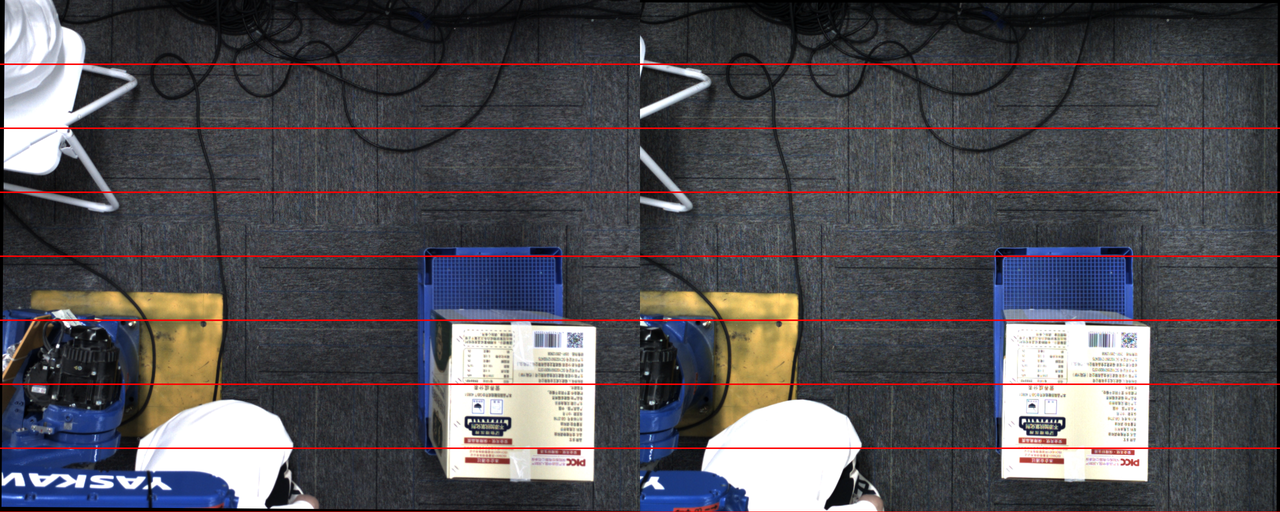 | 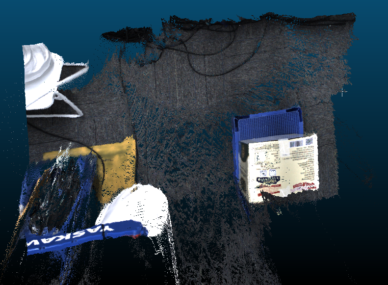 |
| Normal | 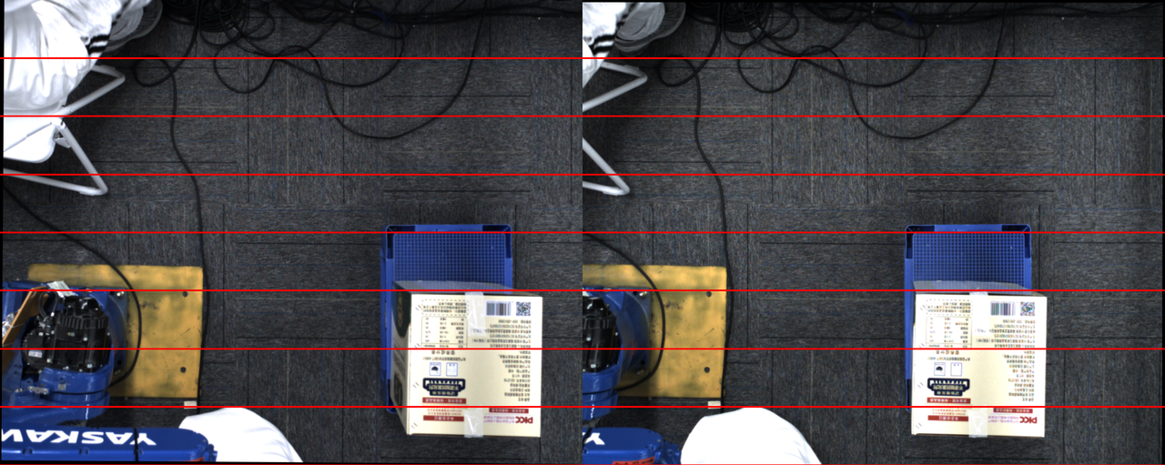 | 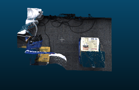 |
1.6 Partial overexposure in the 2D image of the stereo Camera
Issue: The stereo Camera has a "split lighting face" effect, causing partial overexposure in the 2D image
Possible cause: HDR exposure mode is not enabled, and the lighting is abnormal
Solution:
- For general simple large-object scenes, such as sacks and cartons
Enable HDR high dynamic range. You can see that the partially overexposed areas on the workpiece surface can show texture, and the Point Cloud improves.
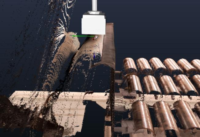
For complex-shaped workpieces with split lighting, such as cylinders and specific shapes
Currently, stereo imaging cannot solve this, as in the following scenarios
1.7 Takt Time optimization for high-resolution stereo photographing
Issue: When using a high-resolution stereo Camera, the Takt Time for a single photograph is too long (a single photograph is nearly more than 8~10s)
Possible cause:
The zoom ratio is set to 1.0, making the image too large for a high-resolution Camera
High dynamic range is enabled, which is equivalent to triggering multiple image captures
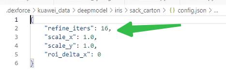
The model Inference uses the default 16 iterations, which takes too long for high-resolution images
Solution:
- Check whether the zoom ratio setting on the photographing interface is 0.5
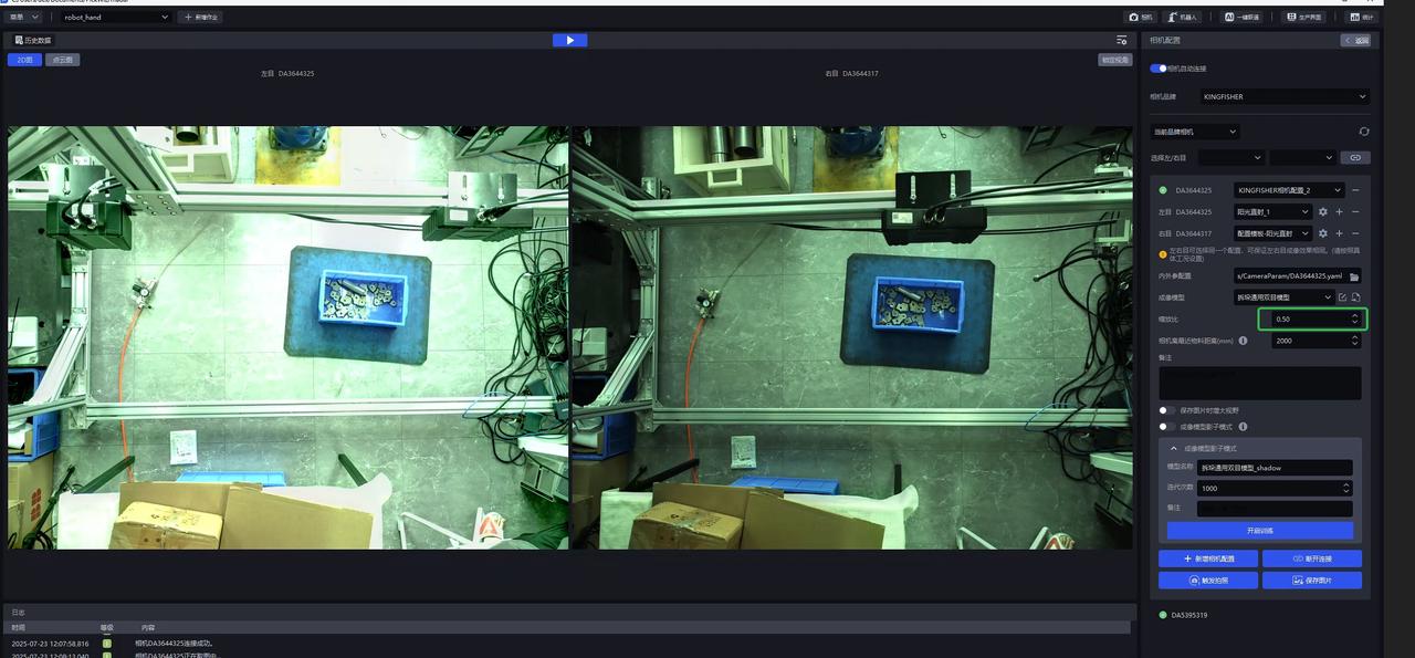
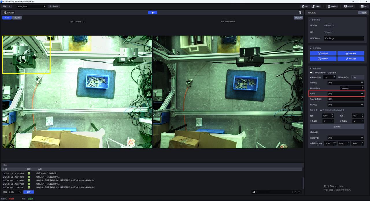
- Check whether high dynamic range is turned off
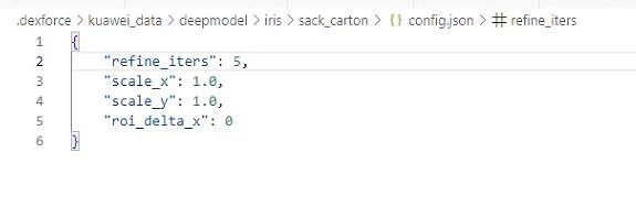
- By modifying the "refine_iters" field in the
C:\Users\dex\.dexforce\kuawei_data\deepmodel\iris\sack_carton\config.jsonfile from 16 to 5, restart the software after the change.
- Note that the Point Cloud effect may worsen at this time. You can use the stereo Shadow mode in the product to adapt to it (requires >=1.7.6).
1.8 Black lines appear in stereo Camera image capture
Issue: Black lines appear in stereo Camera image capture, as shown below.
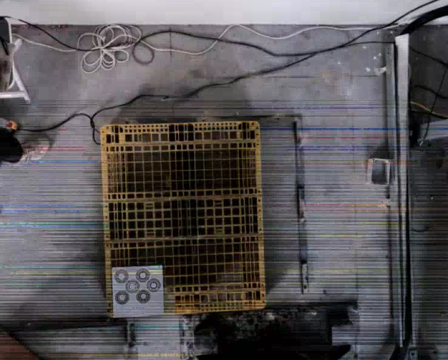

Possible cause: The customer replaced the network cable with a longer one, causing unstable network speed. Network issues cause black lines in images captured by the KINGFISHER stereo Camera
Solution: Prioritize checking the on-site network conditions or the status of the network cable.
2. Mask mode & Shadow mode
2.1 The difference between Mask mode and Shadow mode
Issue: What is the difference between Mask mode and Shadow mode, and what scenarios are they suitable for?
Answer:
Mask mode: refers to data quickly constructed based on texture + synthetic data and directly used for training. Its detection capability is equivalent to the given texture (if multiple textures are provided, it can detect cartons or sacks with multiple textures) in the corresponding scene. It is generally used directly for cases where actual material detection fails (for example, the recent Yushi case, where the detection performance was too poor); versions after 132 all support it. The training duration on the IPC is expected to be within 1 hour.
Shadow mode: refers to real data accumulated after the model runs in the actual scene and then reused for training. The typical use scenario is when a detection success rate of over 95% has already been achieved and the goal is to reach 99.9%. Versions after 130 all support it. The training duration on the IPC is expected to be within 1 hour (with an initial data volume of more than 100 samples).
2.2 Save path of texture data in Mask mode
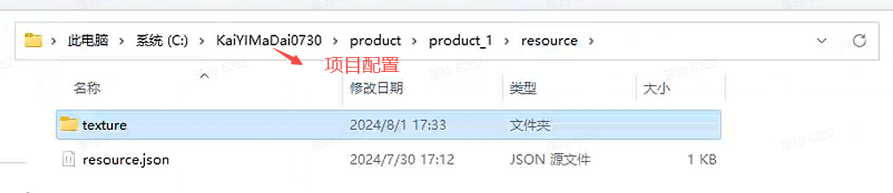
Issue: Where is the texture data saved after training with Mask mode?
Answer: In the corresponding Project configuration folder
2.3 Training new workpieces in Mask mode
Issue: After using Mask mode to train and obtain model A, a different carton is added on site. Can Mask mode continue to be used for training on the basis of A?
Answer: Yes. You only need to replace the model used during Mask mode training with the corresponding model and enter the new texture.
2.4 Mask mode training has no effect
Issue: After using Mask mode, there is no change in the effect. What is the reason?
Possible cause: The workpiece model has not been updated, and the selected texture is incomplete
Solution:
2.5 Mask mode training failed
Issue: Mask mode training failed
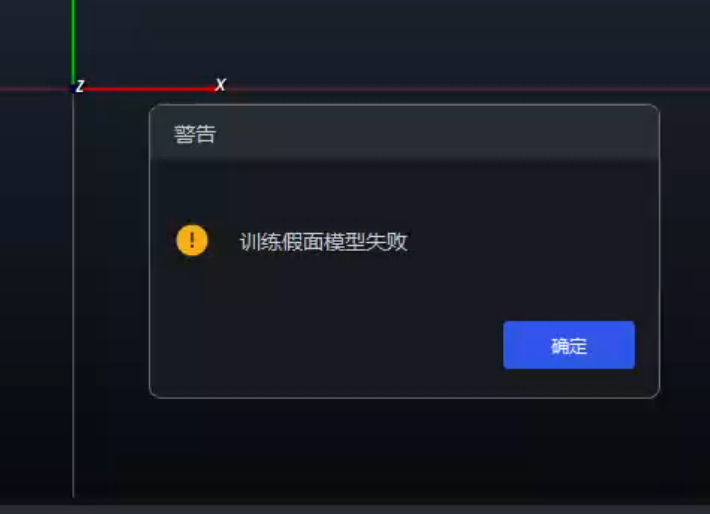
Possible cause:
Solution:
It may be caused by a code bug that prevented the folder from being created successfully
If not, create it and rerun Mask mode or Shadow mode
It may be caused by file corruption due to a direct power-off or direct restart
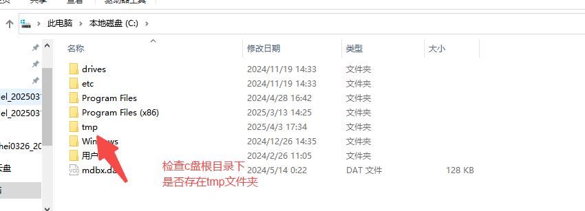
- Check these 5 folders under this path. Each folder contains
info.yaml. If you openinfo.yamland find that the file is corrupted and cannot be opened normally, proceed to step 2
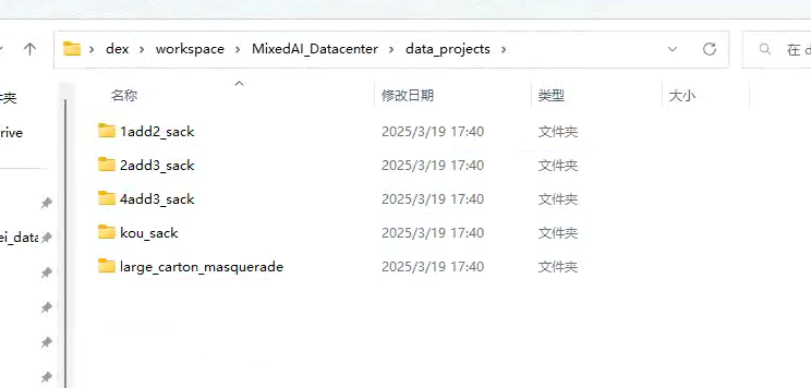
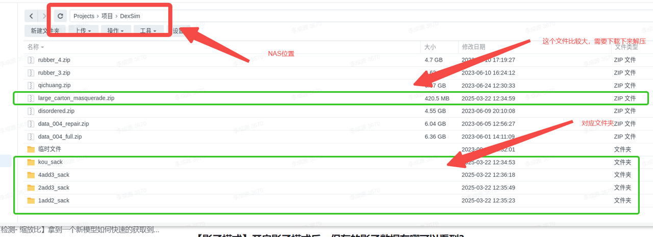
- Find the corresponding folder at the location shown below on the NAS (note that one folder needs to be decompressed). After decompression, replace the folder with the same name in the
data projectsshown above. (First delete the folder indata projects, then update it)
- Check these 5 folders under this path. Each folder contains
2.6 Shadow data save path
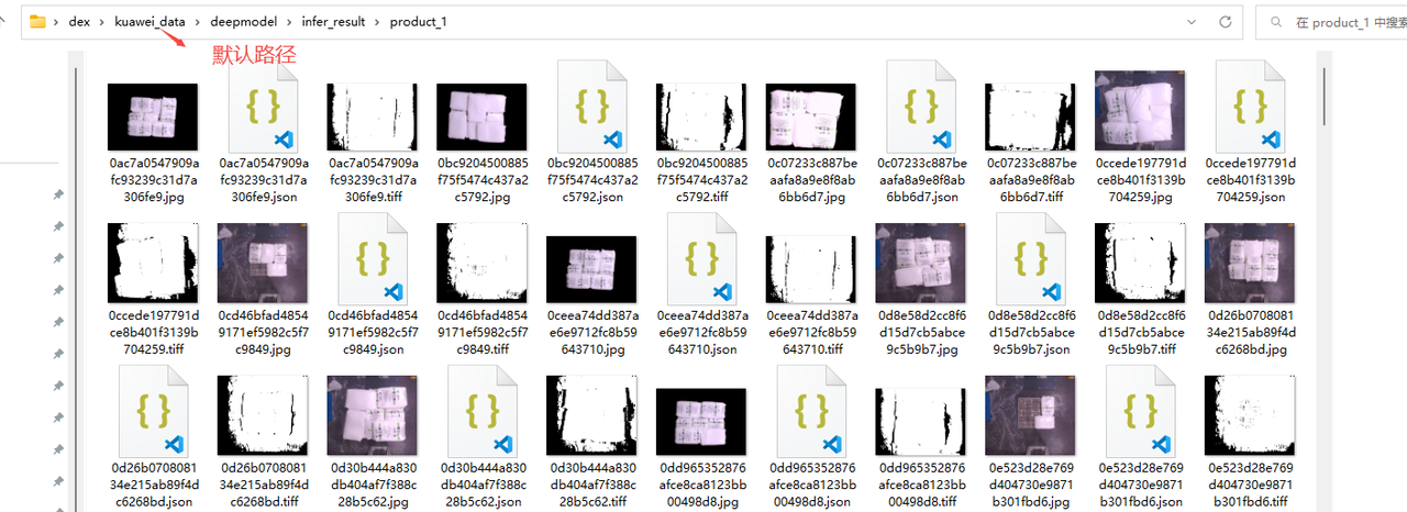
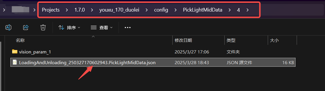
Issue: After enabling Shadow mode, where can the saved shadow data be viewed?
Answer: By default, it is under the kuawei\_data path. The save path can also be modified (it is recommended to use the default path)
2.7 Shadow mode training has no effect
Issue: After using Shadow mode, there is no change in the effect. What is the reason?
Possible cause: The model was not updated, or the workpiece type does not match
Solution:
2.8 Location to enable Shadow mode
Issue: Where is Shadow mode enabled in unordered and ordered scenes?
Answer: Shadow mode is enabled by default in unordered and ordered scenes. If you are not sure, you can check according to the following path
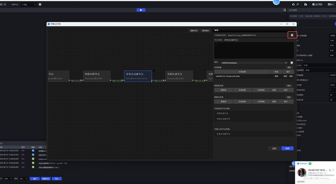
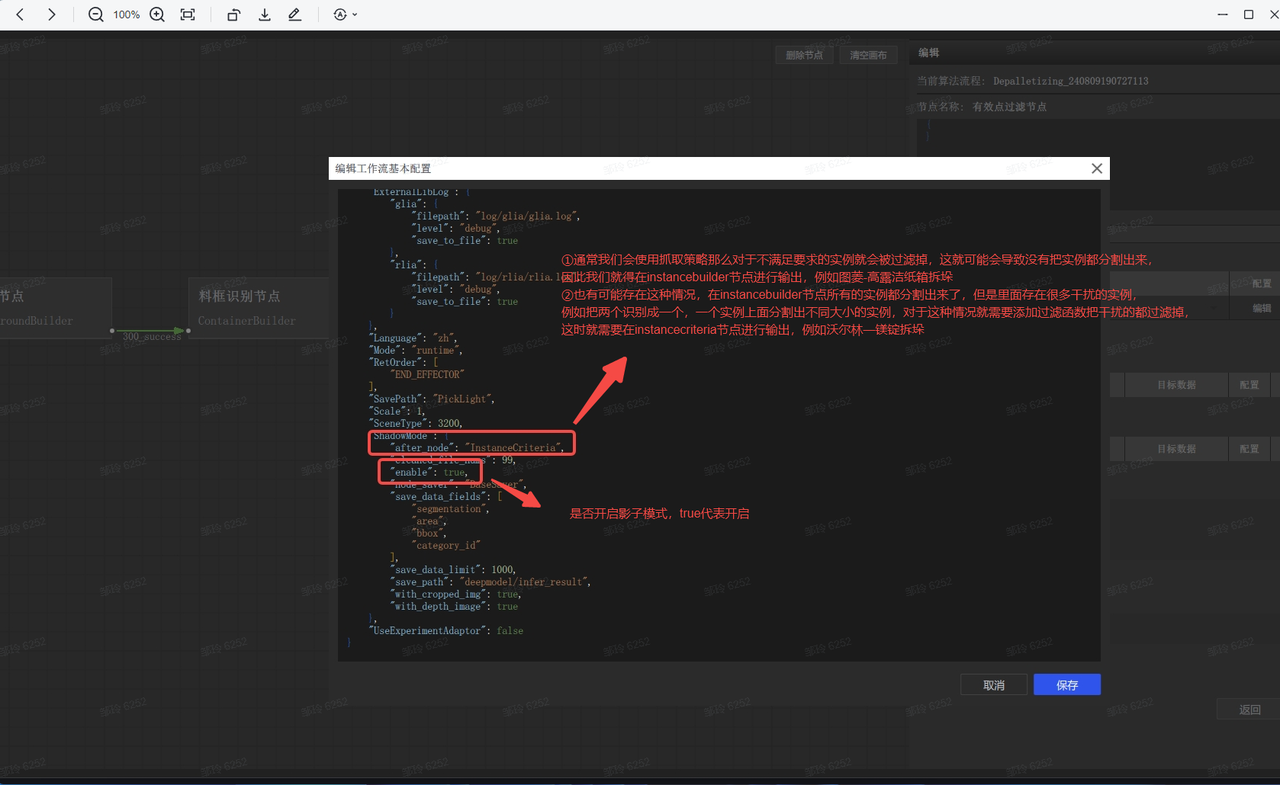
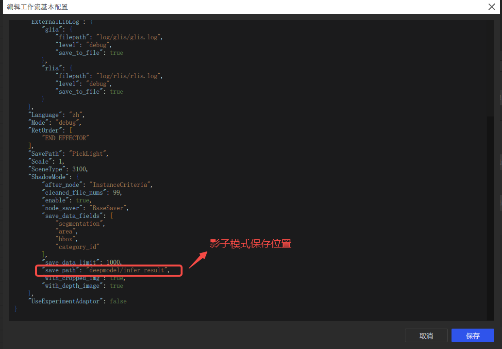
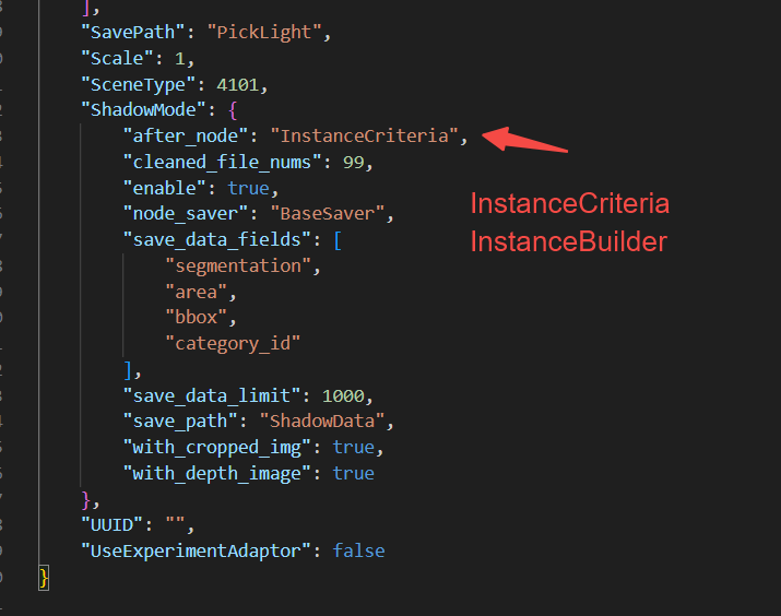
2.9 Modify the Shadow mode save node 【1.6.0-1.7.0】 for all scenes
Issue: How to modify the Shadow mode save node?
Answer: Enter the Project directory and find the task configuration according to the task ID
Enter the configuration and modify the contents of the ShadowMode section
3. Depalletizing scenarios
3.1 2D recognition
3.1.1 Quickly obtain the most suitable zoom ratio
Issue: How to quickly obtain the most suitable zoom ratio
Answer:
Use run.py locally for Inference (Windows)
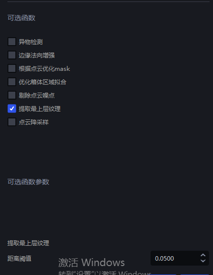
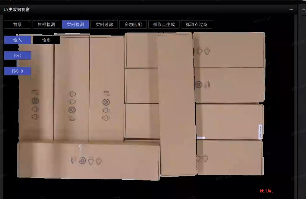
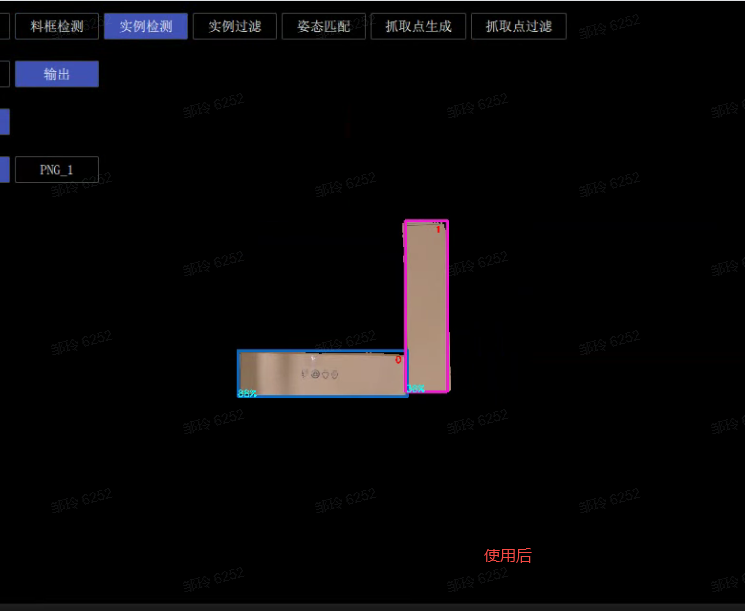
3.1.2 Extract top-layer texture - some instances cannot be recognized
Issue: For cartons of the same size arranged in order, some cartons cannot be detected. Besides optimizing the model, are there any other methods?
Possible cause:
Solution: You can modify the parameters for extracting the top-layer texture so that only the top-layer cartons are retained
3.2 Pick Point processing
3.2.1 Pose adjustment
Issue: The carton coordinates output by the software by default have x pointing to the long side and y pointing to the short side. If y is expected to point to the long side, how should the parameters be set?
Answer: Configure according to two cases
The RZ angle is not fixed (accepts ±180 rotation)
- Just add a fixed 90° rotation in the grasping strategy

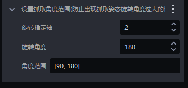
The Rz angle is fixed
- First add a fixed rotation angle to the grasp to make y point to the short side
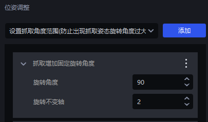
- Then add the setting for the grasp angle range (set the angle range according to the actual situation)
3.3 Picking accuracy
3.3.1 The Pick Point is not at the center - resolution
Issue: The carton instance segmentation is normal and the Mask is complete, but the Pick Point is not at the center. How should it be adjusted?
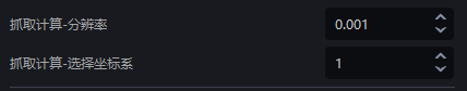
Possible cause: This issue may occur because the grasp calculation - resolution parameter is relatively large, resulting in large spacing in the calculated Mask
Solution: You can modify the size of the grasp - resolution parameter. The tuning suggestion is as follows
Parameter tuning
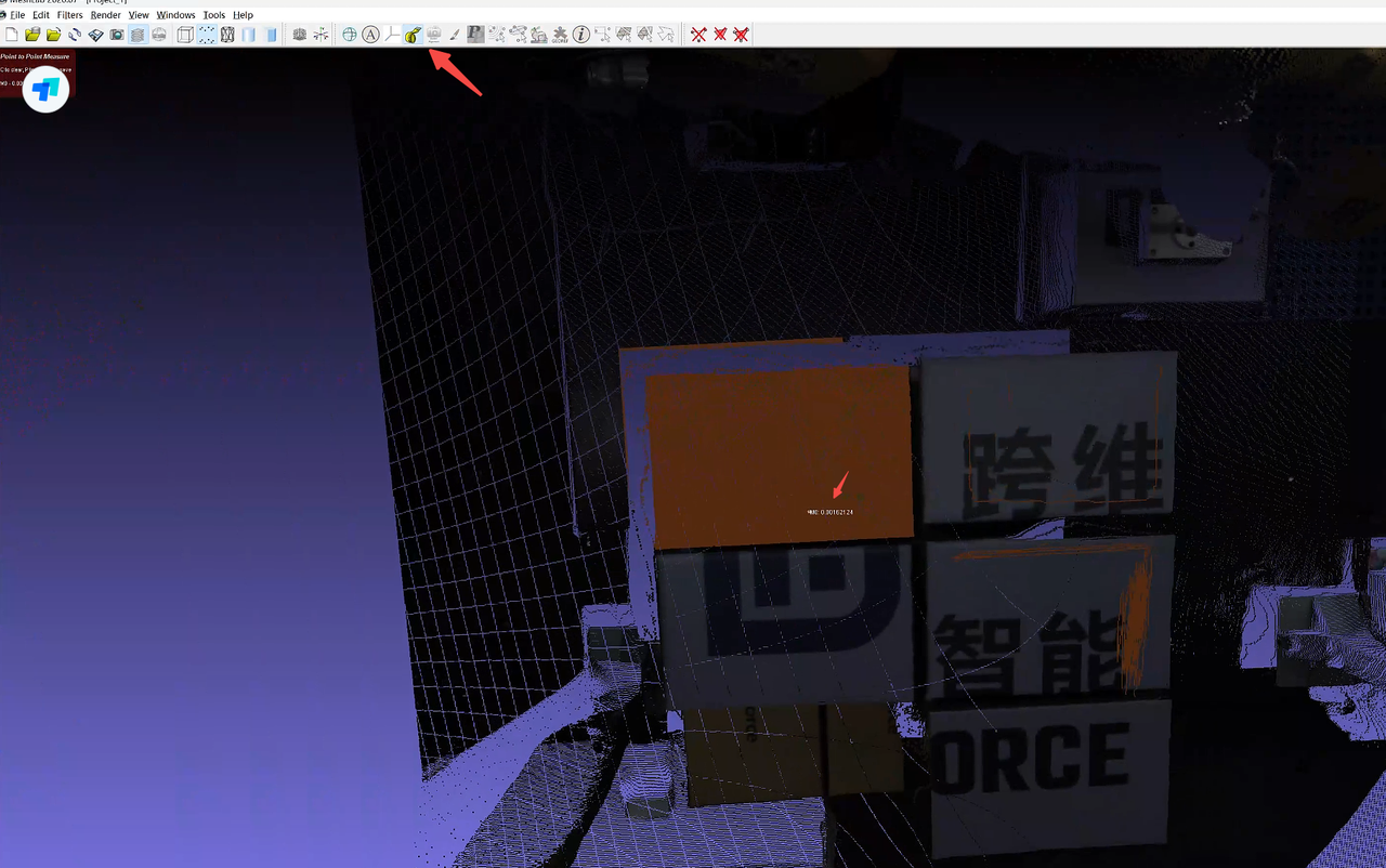
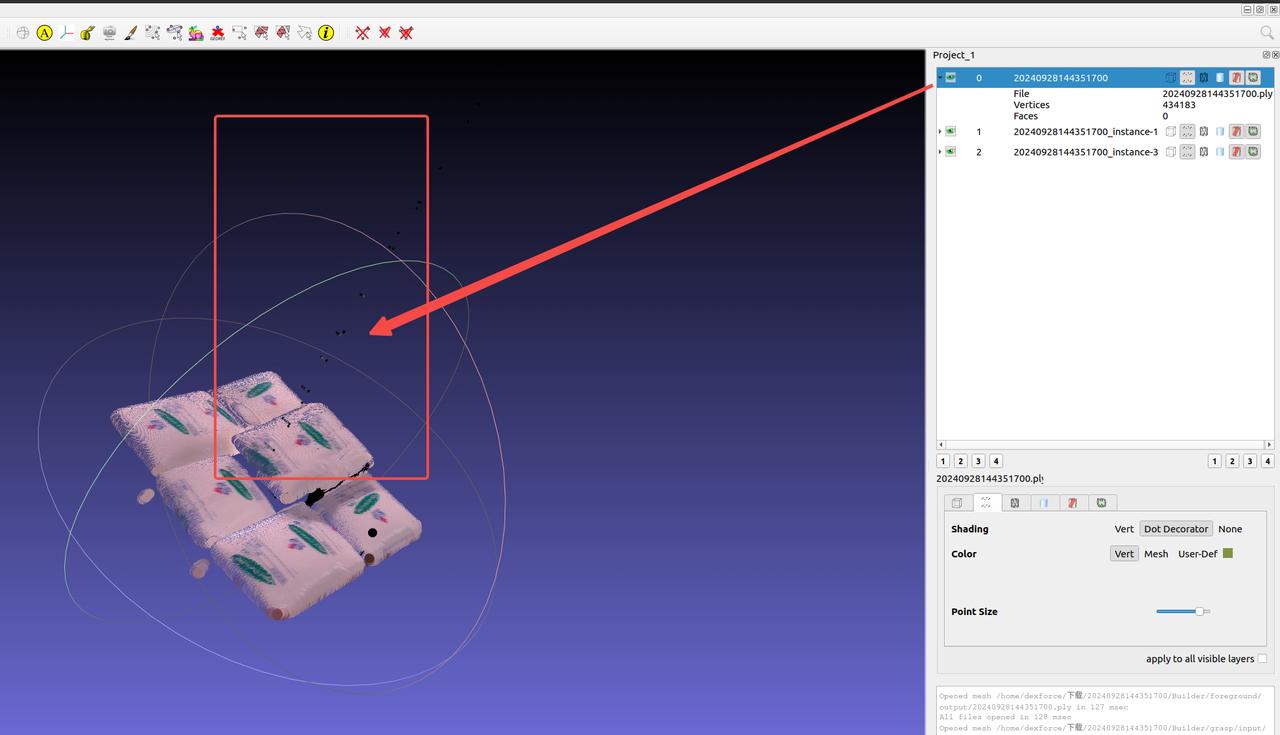
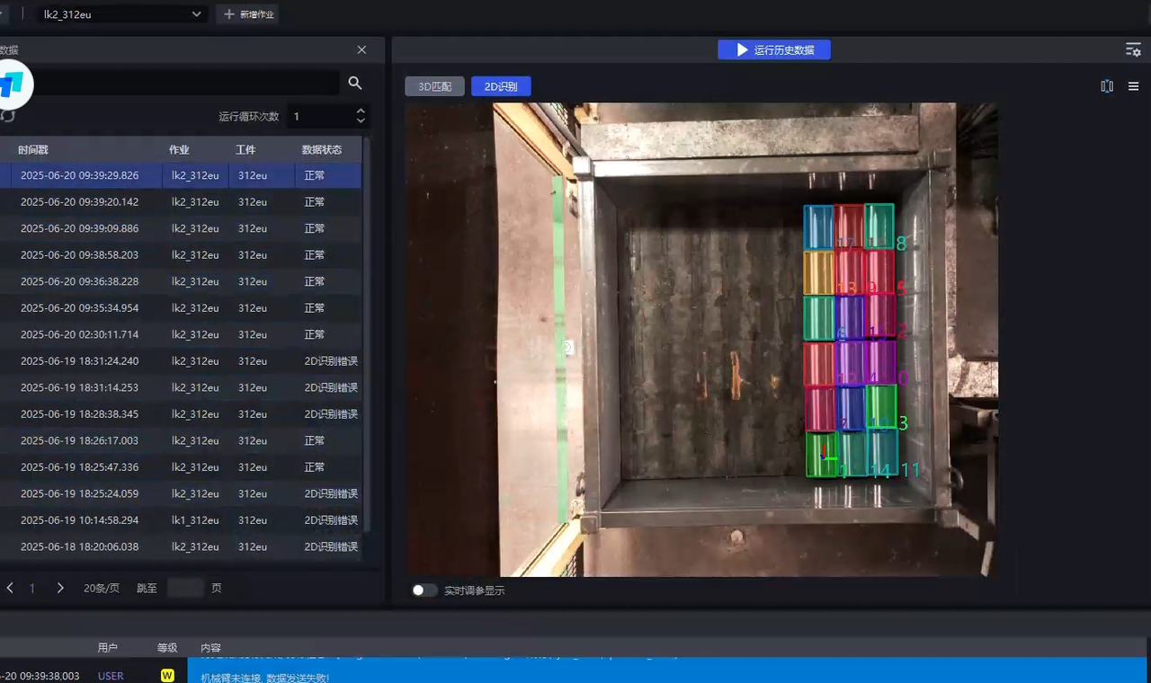
Use Meshlab to open the Point Cloud in the folder where the historical data is located. The file path of the historical data is
C:\Users\dex\kuawei\_data\PickLightMeshlab is a powerful 3D display and manipulation tool. Download address: https://www.meshlab.net/#download
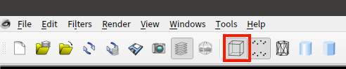
After opening the corresponding Point Cloud in Meshlab, click

Measure the distance between adjacent points and fill in a nearby value
In actual scenarios, the Point Cloud precision of upper-layer objects is smaller, while that of lower-layer objects is larger, so it is recommended to fill in a slightly larger value
As shown below, the measured Point Cloud value is 0.0016, so you can fill in a nearby value such as 0.002 as the Point Cloud precision
3.3.2 Excessive grasp angle
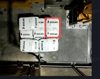
Issue: The sack instance segmentation is normal and the Mask is complete, but the sack bulges, causing the grasp angle to be too large. How can the grasp angle be made smaller?
Solution:
The size of the patch can be adjusted
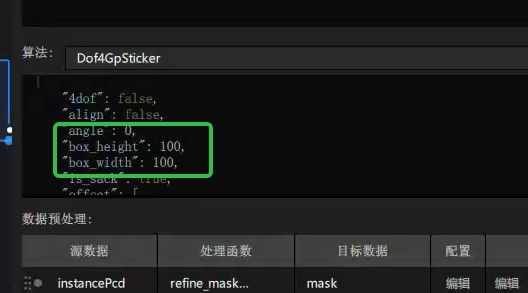
Enter the visualized Workflow, and add
"box\_width" :100and"box\_height" :100(representing the patch size, which can be adjusted according to the actual sack) to thedof4algorithm
3.3.3 Pick Point not centered - segmented into the side
Issue: During detection, segmentation is correct, but the side of the sack is also segmented, causing the grasp to deviate and not land at the center.
Possible cause: The side was also included in the calculation.
Solution: In the vision parameters, change Grasp Calculation - Select Coordinate System from 1 (roi coordinate system) -> 2 (the coordinate system perpendicular to the sack)
3.3.4 Pick Point not centered - large Pick Point deviation
Issue: The segmented Mask is correct and complete, but the Point Cloud output by the Pick Point generation node is incorrect?
Possible cause: This is generally caused by incorrect parameter settings in the optional functions. For example, if the average distance ratio parameter in the Point Cloud removal function is set too small, a large number of sack Point Cloud points will be removed, causing the Pick Point to shift.
Solution: Adjust the parameter settings.
3.3.5 Pick Point not centered - rough segmentation
Issue: The sack segmentation box is too large and the Mask sticks to the lower layer, causing the Pick Point to shift. How can this be resolved?
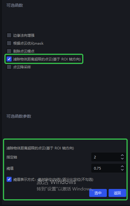
Solution: Because the Mask is too large, the main body Point Cloud is connected to the lower-layer Point Cloud. The lower-layer Point Cloud needs to be removed so that only the upper-layer Point Cloud is retained.
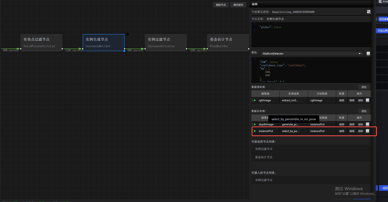
- In the vision parameters, check the optional function to filter out Point Clouds whose object distance exceeds the limit (based on the roi axis direction) (v1.4.2)
3.3.6 Pick Point not centered
Issue: From the segmentation result image, both the segmentation and Mask are normal, but the Pick Point is not at the center. How can this be resolved?
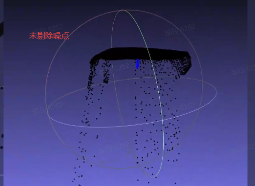
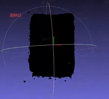
Possible cause: In this example, too many noise points are attached.
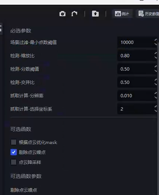
Solution: Check the output of the grasp node in the corresponding historical data. You can enable Point Cloud noise removal.
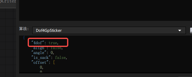
3.3.7 Pick Point mode: 4-axis/6-axis (≤1.4.1)
Issue: When the robot arm is 4-axis, where is the corresponding coordinate output configured?
Answer: If the robot arm is 4-axis, set 4dof to true in the dof4 algorithm configuration of the grasp generation node; if it is 6-axis, set it to false (you need to enter the visual Workflow).
3.4 Optional functions
3.4.1 fill_hole Point Cloud noise appears after hole filling
| Version dependency | Add location | Source data | Target data |
|---|---|---|---|
| PickLight >= 1.5.0 | Post-processing of foreground node or pre-processing of instance generation node | depthImage | depthImage |
Recommended for use with glia-0.3.3 and later.
Issue: In the visual Workflow, when using fille_hole to fill holes, pyramid-like stepped noise appears, for example:
Possible cause: Areas with depth 0 in the depth image affect hole filling. This was fixed in PickWiz versions >= 1.5.0.
Solution:
It is recommended to contact product/R&D support to update the on-site software version.
Confirm or upgrade
glia >= 0.3.3. Refer to Windows Development Environment Setup - PickLight. As shown below, find the corresponding download version forglia-0.3.3.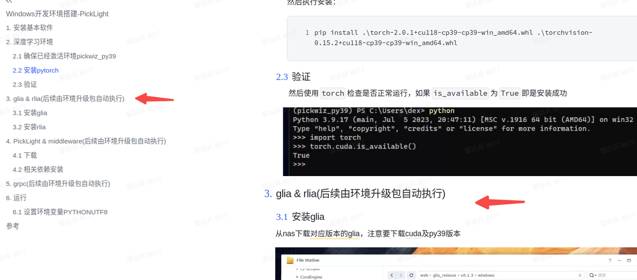
Confirm or upgrade
pickwiz >= 1.5.0or upgrade the backend whl package torelease-1.4.5.1(commit version >=xxx, PR pending merge )
Restart the software after the update, then rerun the historical data.
3.4.2 Using the filter_by_color function
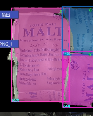
Issue: False positives are generated during instance generation, detecting the bottom pallet or other parts by mistake.
Solution: When false positives occur during instance generation and the bottom pallet or other areas are mistakenly detected as workpieces to be picked, first observe the differences between these detected instances and normal workpieces.
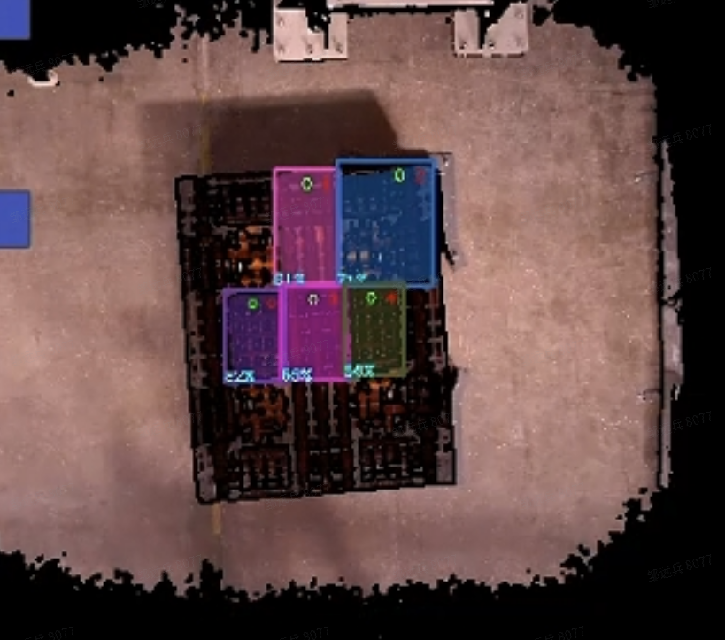
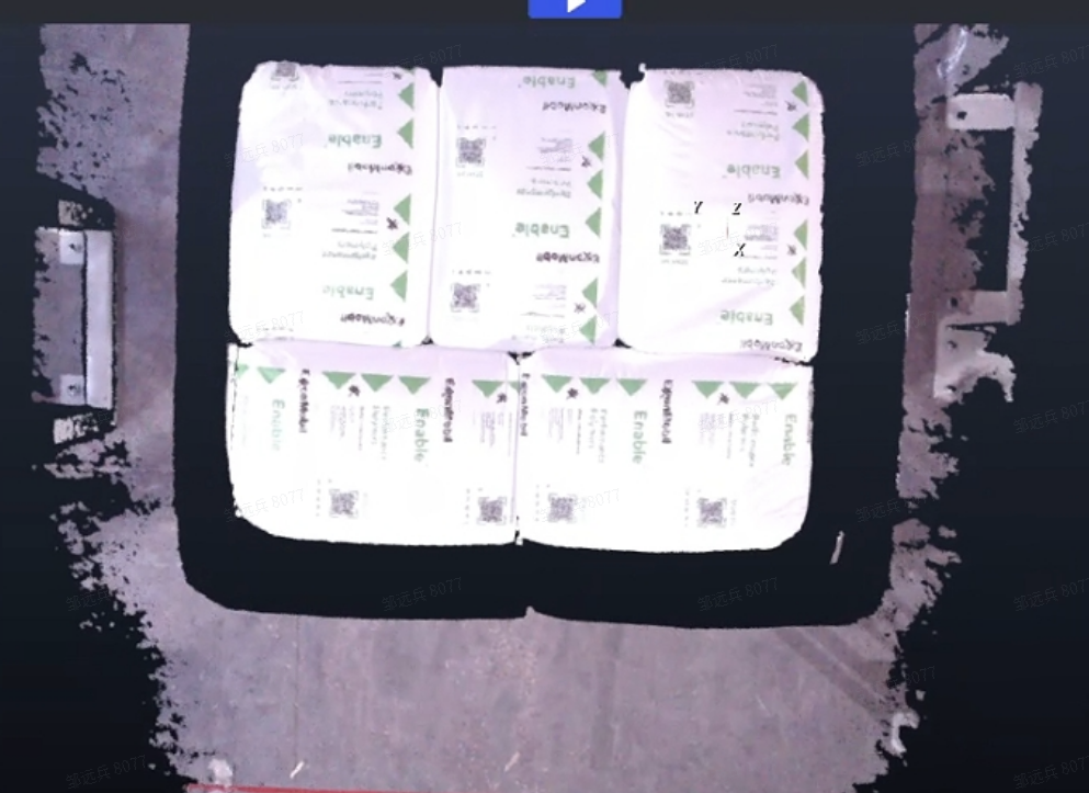
For scenes like the one above where the sack and pallet differ greatly, enter the visual Workflow and add the filter_by_color function to filter according to the specified upper and lower color bounds.
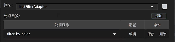
- Add
filter_by_colorin the instance filter node.
- Parameter description
| Parameter | Setting value | Description |
|---|---|---|
| min_c | 0.1 | Minimum value for color filtering; 0 is black and 1 is white |
| max_c | 2 | Maximum value for color filtering; cannot be smaller than `min_c` |
| threshold | 0.7 | Filtering Threshold. If the ratio of the number of pixels within the filtering range (`min_c`, `max_c`) in the instance Mask to the Mask area is lower than this Threshold, the instance is filtered out |
| inverse | false | Whether to invert. If `true`, points in the Mask whose color is less than `min_c` or greater than `max_c` are used to calculate the Threshold |
With the above parameter settings, pallet instances containing black can be filtered out, leaving only sack instances.
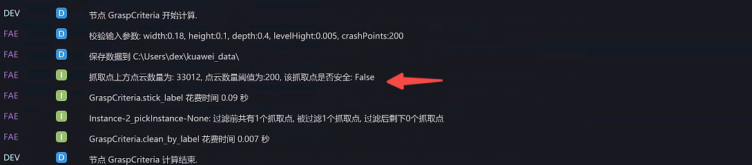
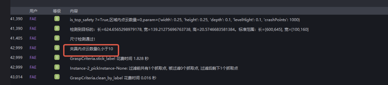
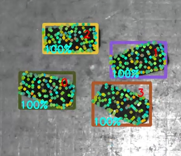
3.4.3 is_top_safety Whether there is other occlusion above the Pick Point
Issue: How can you determine whether the Target Object to be picked is safe and unobstructed in some scenarios?
Answer: You can add the is_top_safety function in the instance filter node.
- Parameter description
| Parameter | Default value | Description |
|---|---|---|
| x_length | 1.0 | Required parameter for cuboid generation, used to determine whether there is an occlusion within the length range of the Pick Point along the pose x direction |
| y_width | 1.0 | Required parameter for cuboid generation, used to determine whether there is an occlusion within the width range of the Pick Point along the pose y direction |
| z_depth | 2.0 | Required parameter for cuboid generation, used to determine whether there is an occlusion within the width range of the Pick Point along the pose z direction |
| bindwidth | 0.1 | Distance Threshold in the z direction, in m. Point Clouds whose height difference from the Pick Point in the z direction exceeds this distance are considered occlusion points |
| num_threshold | 1000 | If the number of occlusion points exceeds this Threshold, the Pick Point is considered occluded |
| debug | false | Whether to save Point Cloud data, used to observe whether the cuboid generation is reasonable |
| save_path | "" | Data save path. Note that on Windows, paths are separated with \\ |
3.4.4 is_safety Whether the gripper at the Pick Point collides
Issue: What is the purpose of the is_safety function?
Answer: It is used to filter out Pick Points that may result in collisions, and is suitable for cases where a robot arm grips an object and the gripper model is known.
- Parameter description
| Parameter | Default value | Description |
|---|---|---|
| prewin | 100 | Unit: pixels. Generates a Mask within a specified pixel range around the Pick Point for subsequent collision-range evaluation. If this value is too large, it may increase runtime and cause calculation anomalies. It is recommended to set it slightly larger than the pixel length of the long side of the workpiece Mask itself. You can evaluate it by checking the data in `debug_vis` |
| threshold | 1.0 | Threshold for determining whether the grasp pose is safe. If the number of Point Cloud points inside the gripper exceeds the Threshold, it is judged unsafe |
| roi_crop | true | Whether to crop the Point Cloud and retain only the Point Cloud within the `roi3d` range |
| debug_vis | "" | Debug data save path. Saves information from the debugging process to the specified path: `mask.png`: Mask range generated according to the `prewin` parameter `object_mask.png`: instance object Mask `shell_mask.png`: result of subtracting the above two Masks, used to determine the surrounding range for collision checking `crop.ply`: surrounding Point Cloud used to determine collision |
| use_projected_mask | false | Whether to use model projection. If `false`, the `mask` passed in from the instance generation node is used. Enable this only when the workpiece itself to be picked has an accurate model |
- Usage log
4. Loading and unloading scenarios (ordered/unordered)
4.1 Deep Learning model
4.1.1 Incomplete model recognition
Issue: The model recognition is incomplete. The Inference count across multiple images is capped at a maximum value (generally 20).
Possible cause: When the model was exported, the maximum recognizable count was set to (20).
Solution: Contact the model provider and export the model again.
4.1.2 Abnormal keypoints in model detection
Issue: Abnormal keypoints appear in model detection.
Possible cause: This issue occurs because when we use one-click connectivity for model training, the keypoints are generated by our own downsampling. When we receive the trained model, new keypoints are generated.
Solution: The keypoints need to be replaced with the new ones.
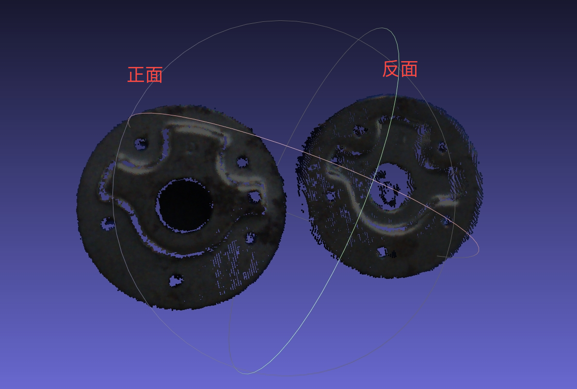
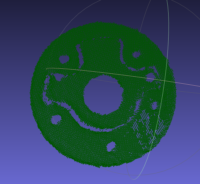
4.1.3 Method for creating dual/multi-templates
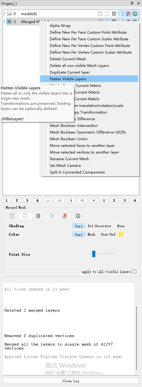
Use the Camera to capture the Point Cloud files of the front and back sides of the workpiece, color them separately, align them with the model CAD, and then merge the colored front and back Point Cloud files together as the template Point Cloud file; perform point-by-point coloring on the keypoint Point Cloud file so that the two colors are evenly spaced.
Procedure:
|
|
|---|---|
|
 |
|    |
|  |
| |
| Like this: 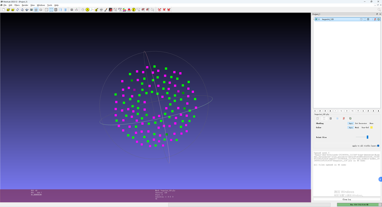 |

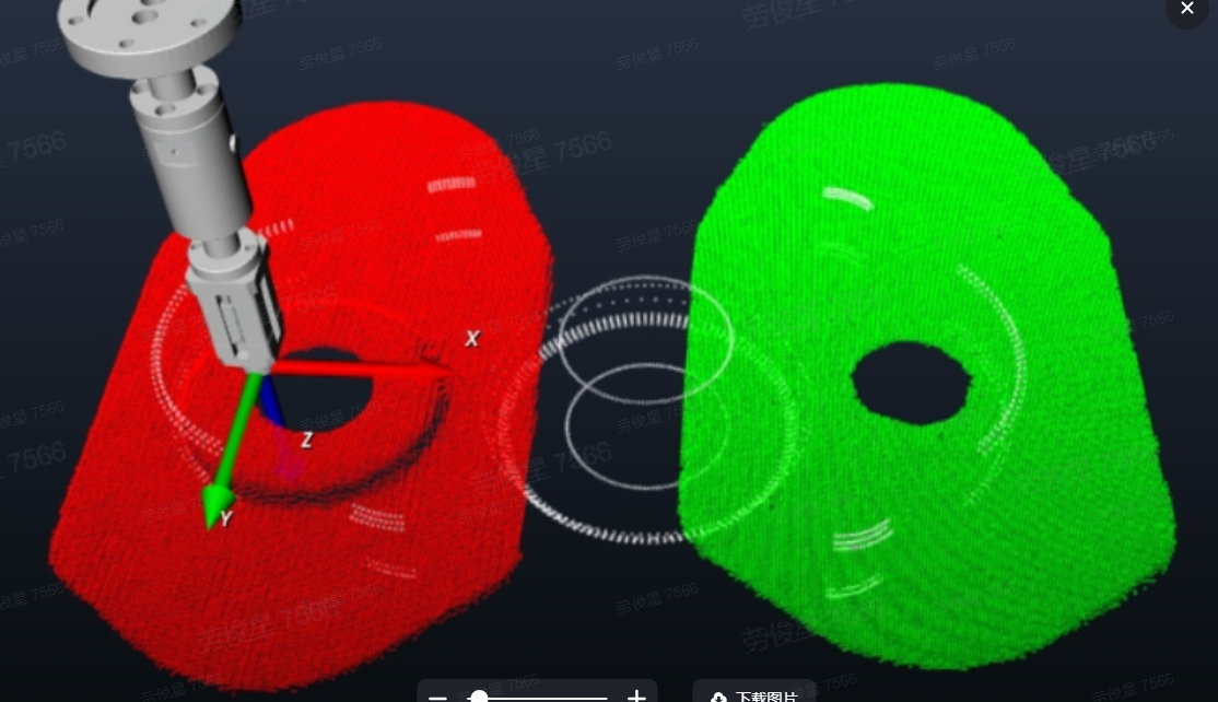
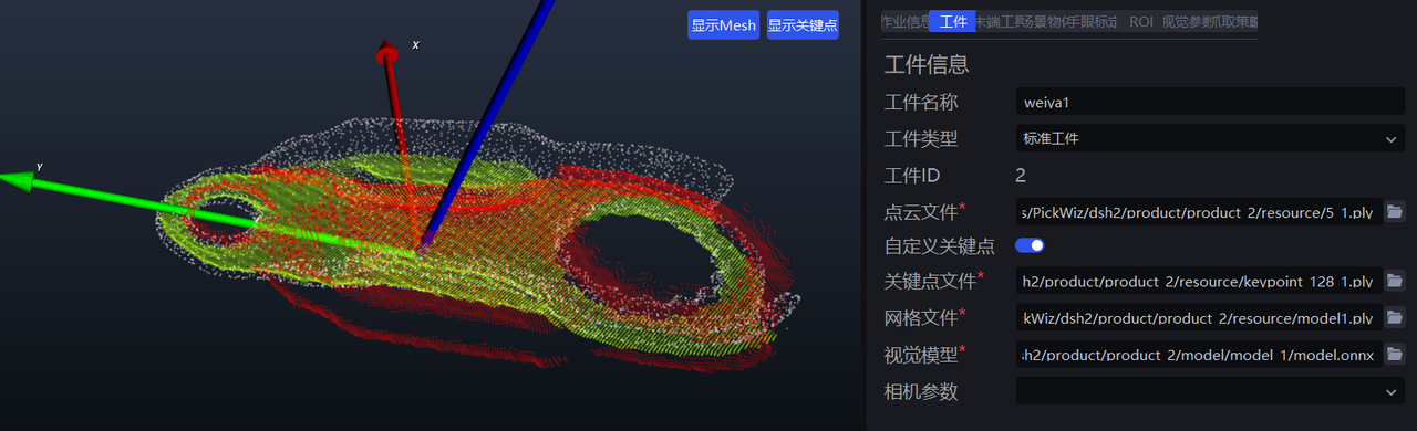
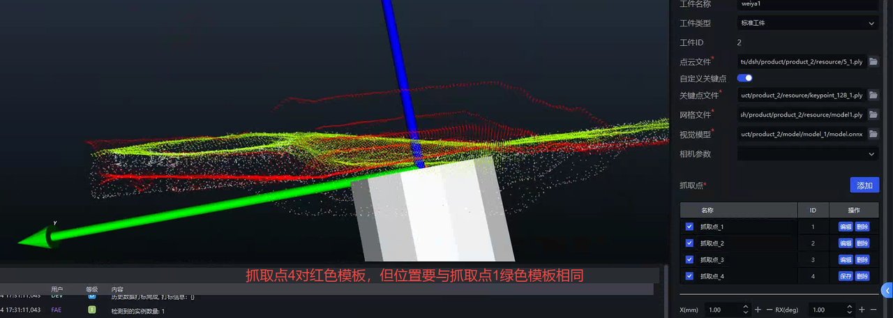
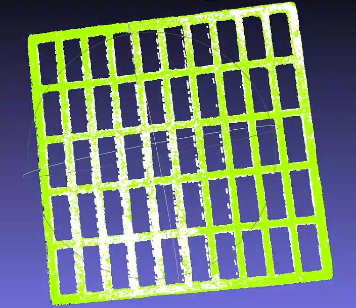
4.1.4 Method for creating and using dual templates with SpitialRansc registration for flat workpieces with identical front and back shapes
Prepare three types of files
Keypoint ply file (
keypoint_128.ply)Front and back Point Cloud model files. These are generally cut out from the scene Point Cloud, with the front template colored green and the back template colored red. (
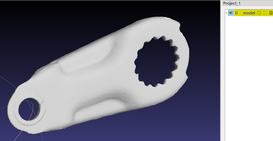
point_front.ply,point_back.ply)Mesh model (
model.ply)
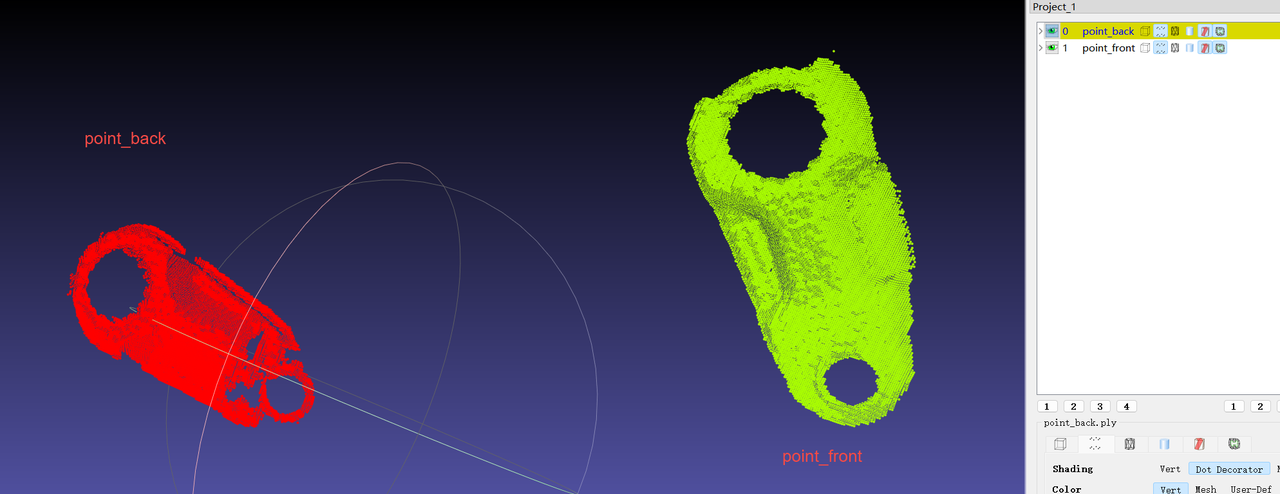
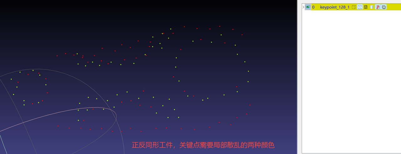
【For 3D parts, use layered dual-color keypoints, and the Point Cloud template only needs the Point Cloud visible to the Camera】
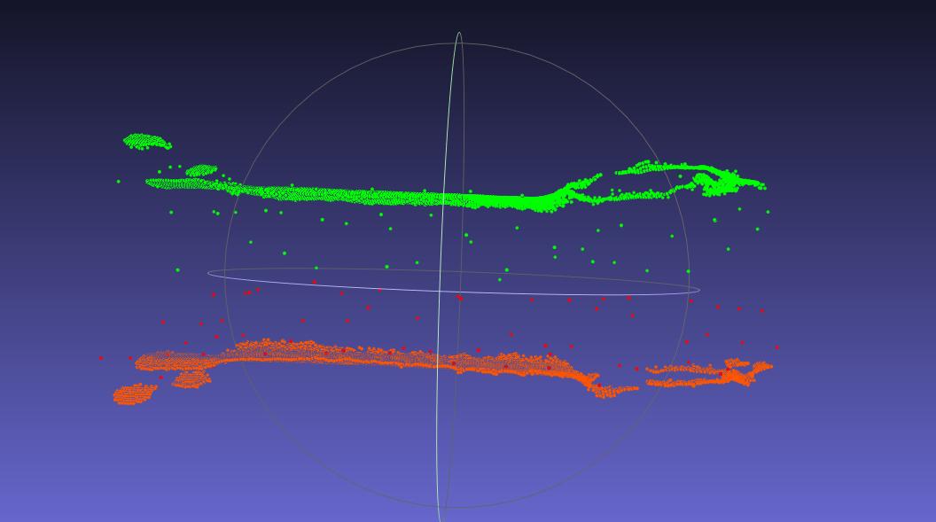
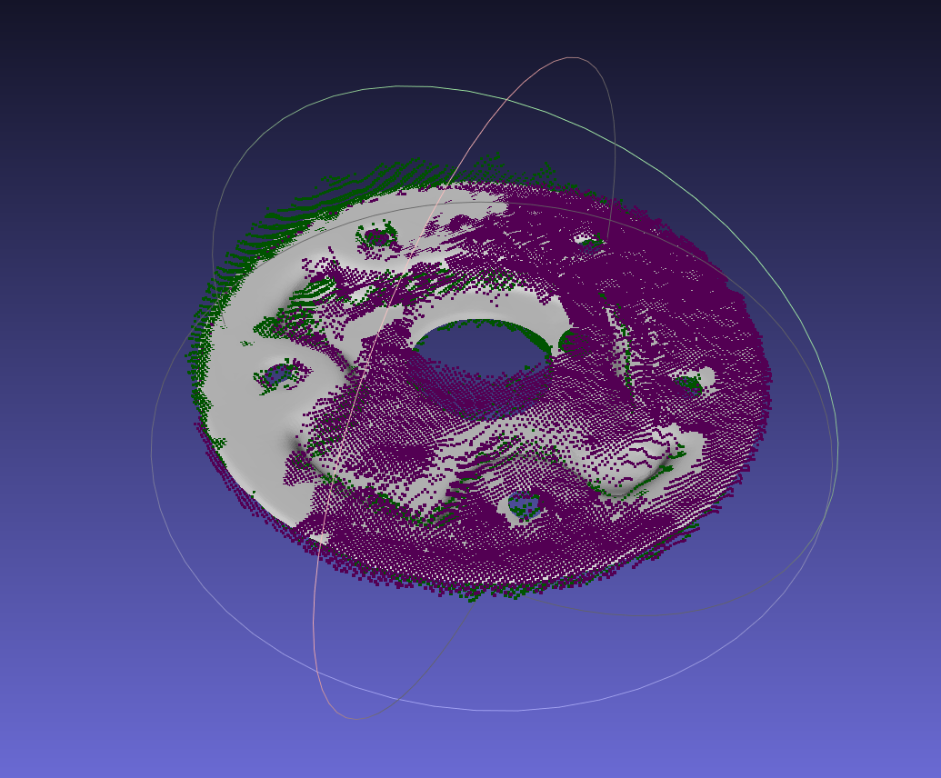
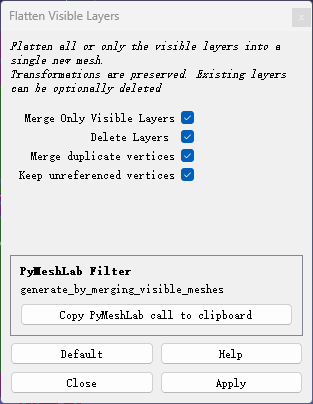
- After aligning the two Point Cloud templates to the CAD, merge the Point Clouds to generate a dual-template Point Cloud ply file.【After aligning the Point Cloud files to the CAD, save each template separately to avoid having to realign them when adjusting templates later】
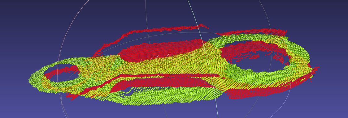
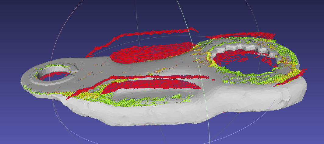
Import the three files into pickwiz
【Note】: Check whether the dual Point Cloud templates are already aligned and colored in two colors, and check whether the keypoints are locally scattered in two colors. The dual colors of the templates and keypoints must correspond.
Create Pick Points
【Note】: Create the Pick Points in order, and read the requirements for creating each Pick Point carefully.
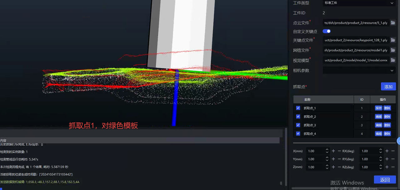
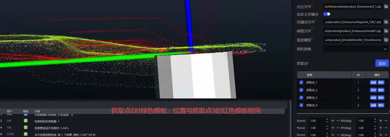
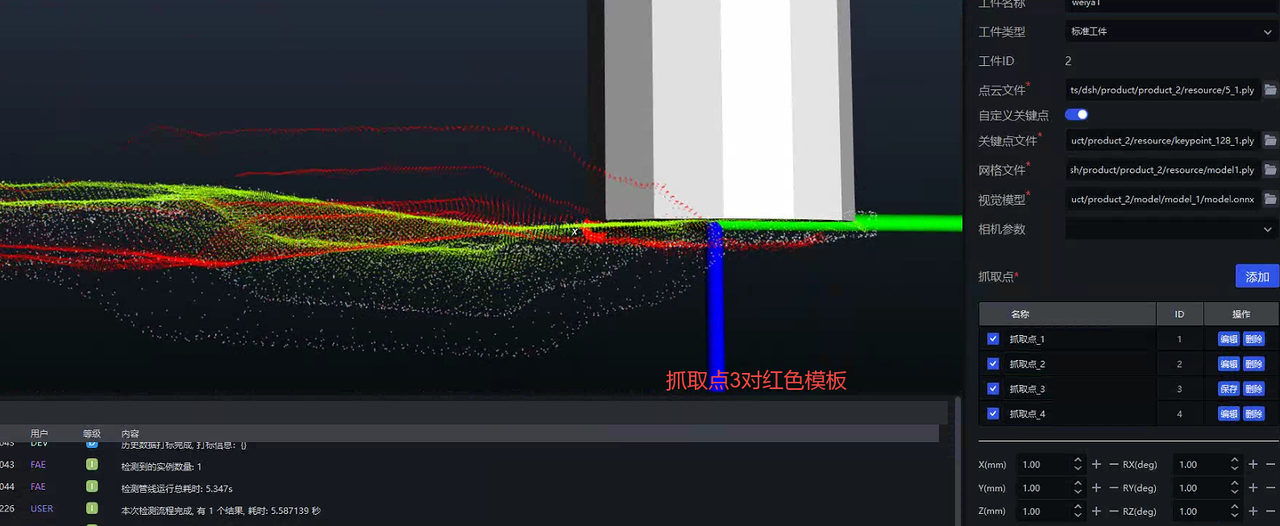
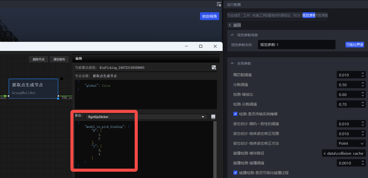
- Open the visualization interface and add the dual-template binding information
{
    "model_to_pick_binding": {
        "0": [
            1,
            2
        ],
        "1": [
            3,
            4
        ]
    }
}
- Add the option to select "Pick Point index" in the Robot settings
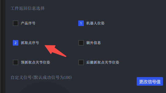
- Click Run. The returned Pick Point index has 4 possible values (1,2,3,4). If high accuracy is required, use a script to teach all 4 Pick Points.
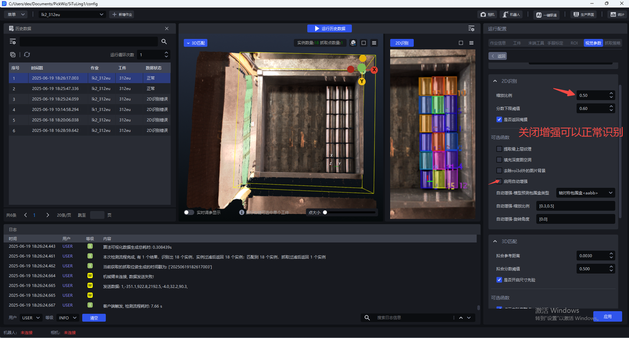
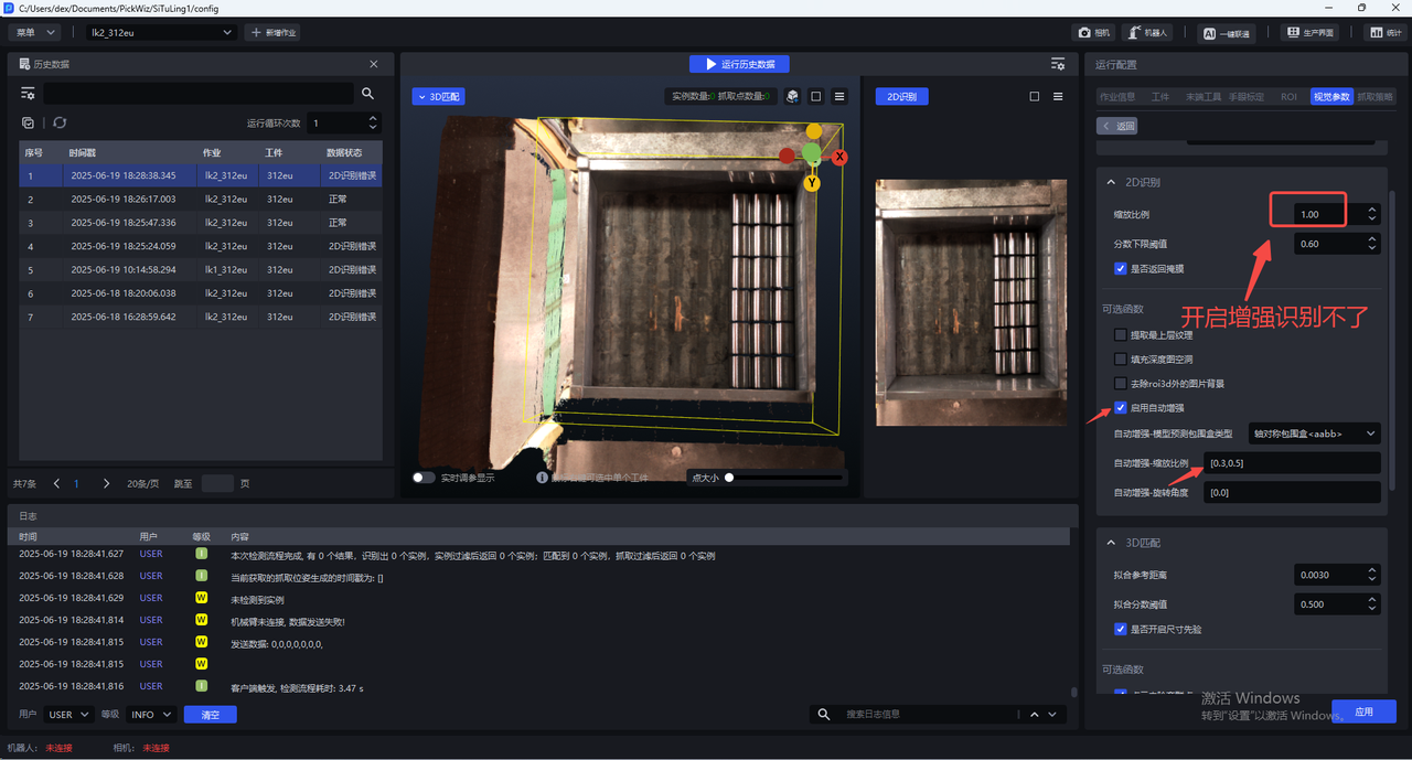
4.1.5 Using Auto Enhancement: Improve prediction performance through data augmentation
Please see the detailed introduction in General Workpiece Vision Parameter Tuning Guide
4.1.6 Correctness of the CAD model used for data rendering
Current ways to obtain the CAD model:
The customer directly provides the original CAD
Scan the actual workpiece
Whichever method is used, please ensure the CAD model is correct (dimensions, orientation, type, etc.)
Counterexample 1: The scanned workpiece Point Cloud is inconsistent with the actual workpiece (opening angle is inconsistent)
4.1.7 TRT model export
When exporting the onnx model, add the
use-trtoptionpython -m mixedai.scripts.export \ --config-file config_path \ --model-file model_path \ --sample-image image_path \ --use-trtUse glia to export the trt model
The following operations are all in the
pickwiz\_py39environment,conda activate pickwiz\_py39- rcnn
python -m glia.dl.utils.trt_converter \ --onnx ONNX_file_path, e.g. xxx.onnx \ --image image_file_path, e.g. xxx.png \ --model-type rcnn \ --saveEngine xxx.trt \- yolo
python -m glia.dl.utils.trt_converter \ --onnx ONNX_file_path, e.g. xxx.onnx \ --model-type yolo \ --saveEngine xxx.trt \- stereo
python -m glia.dl.utils.trt_converter \
        --onnx ONNX_file_path \
        --model-type stereo \
        --saveEngine xxx.trt \
        --optShapes=image1:1x3x480x640,image2:1x3x480x640 \
        --fp32 \
        --workspace=6000 \
        --tacticSources=-CUDNN,+CUBLAS \
        –-builderOptimizationLevel=3
For more detailed export instructions, see: http://doc.open3dv.site/glia/doc/master/text/application/trt_converter.html
- Use glia to run Inference on the onnx model and trt model, and check whether the results are consistent
python -m glia.dl.utils.inference --image-file "./*.png" \
--model-file .trt .engine or .onnx model \
--output-dir ./ \
--bbox-mode aabb (or obb)\
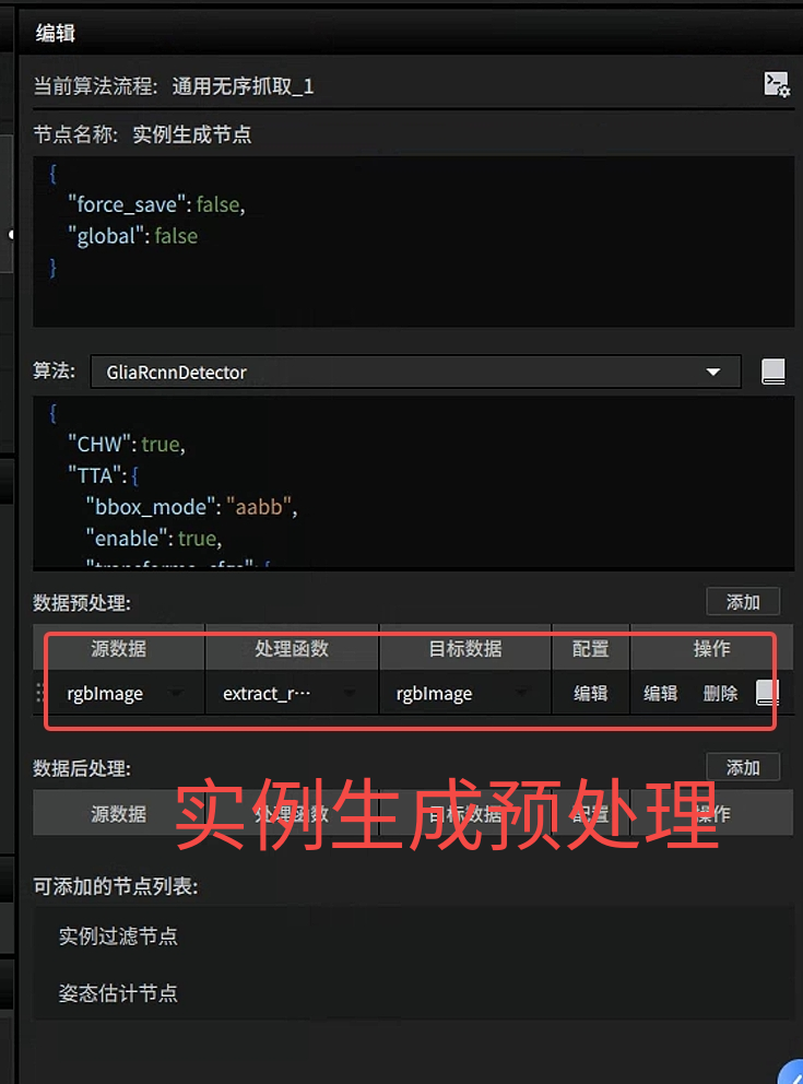
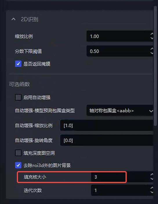
--scale 1.04.1.8 extract_roi3d_rgb settings
Remove the corresponding image content outside the ROI3D area to remove the Background
Parameter: fill kernel size
Before 1.5.1: kernel_size
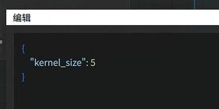
After 1.5.1:
*******Note*******If Point Cloud data is missing in the area to be detected, holes may appear in the image after Background removal, affecting detection performance. In this case, increase the fill kernel size to fill the holes. The specific effect is as follows
| kernel_size | Original image | Detection result |
|---|---|---|
| 5 | 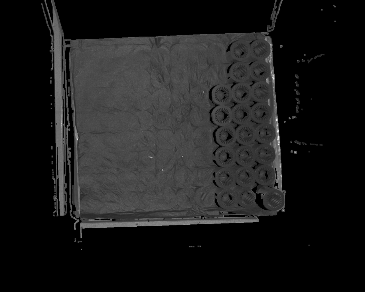 The default configuration is 5. If Point Cloud data is missing in the area to be detected, there may be many holes in that area, affecting detection results The default configuration is 5. If Point Cloud data is missing in the area to be detected, there may be many holes in that area, affecting detection results | 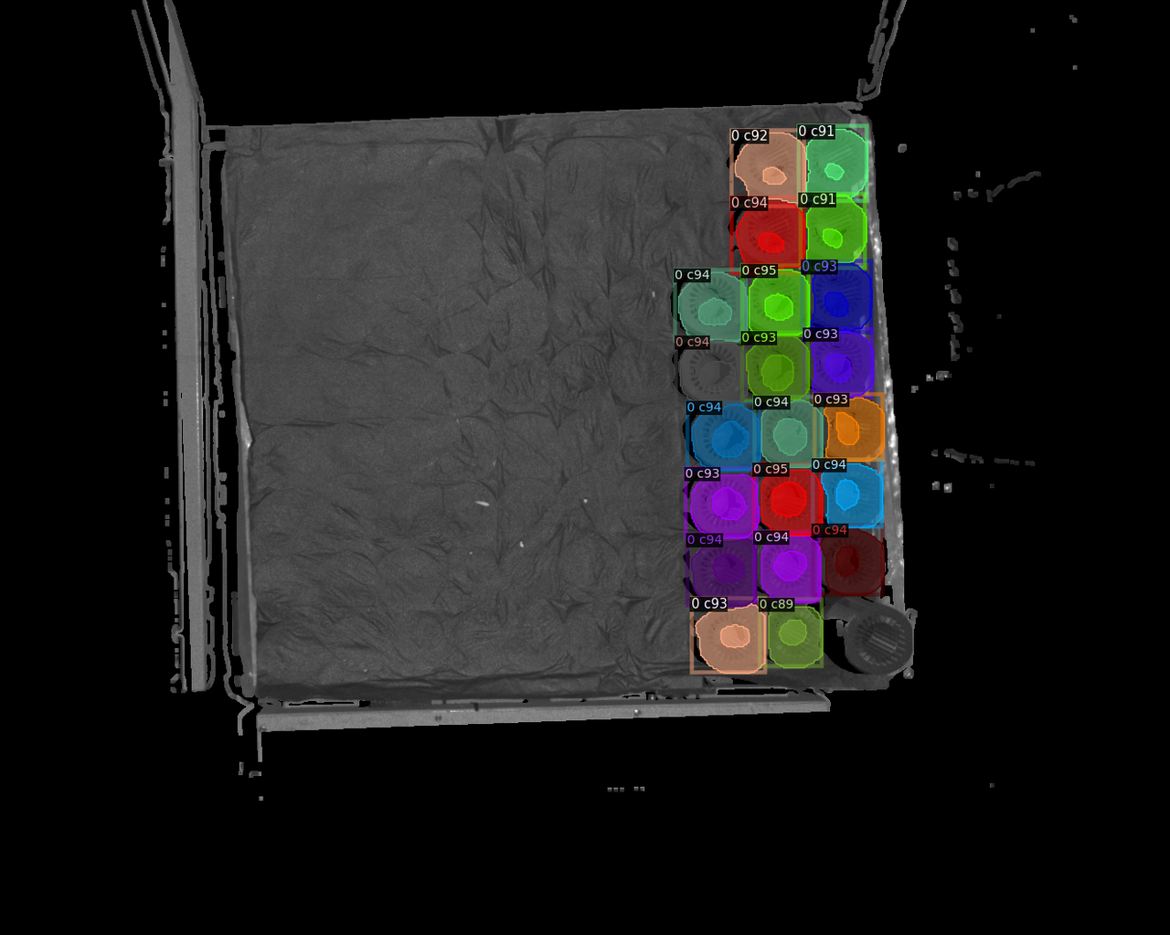 |
| 7 | 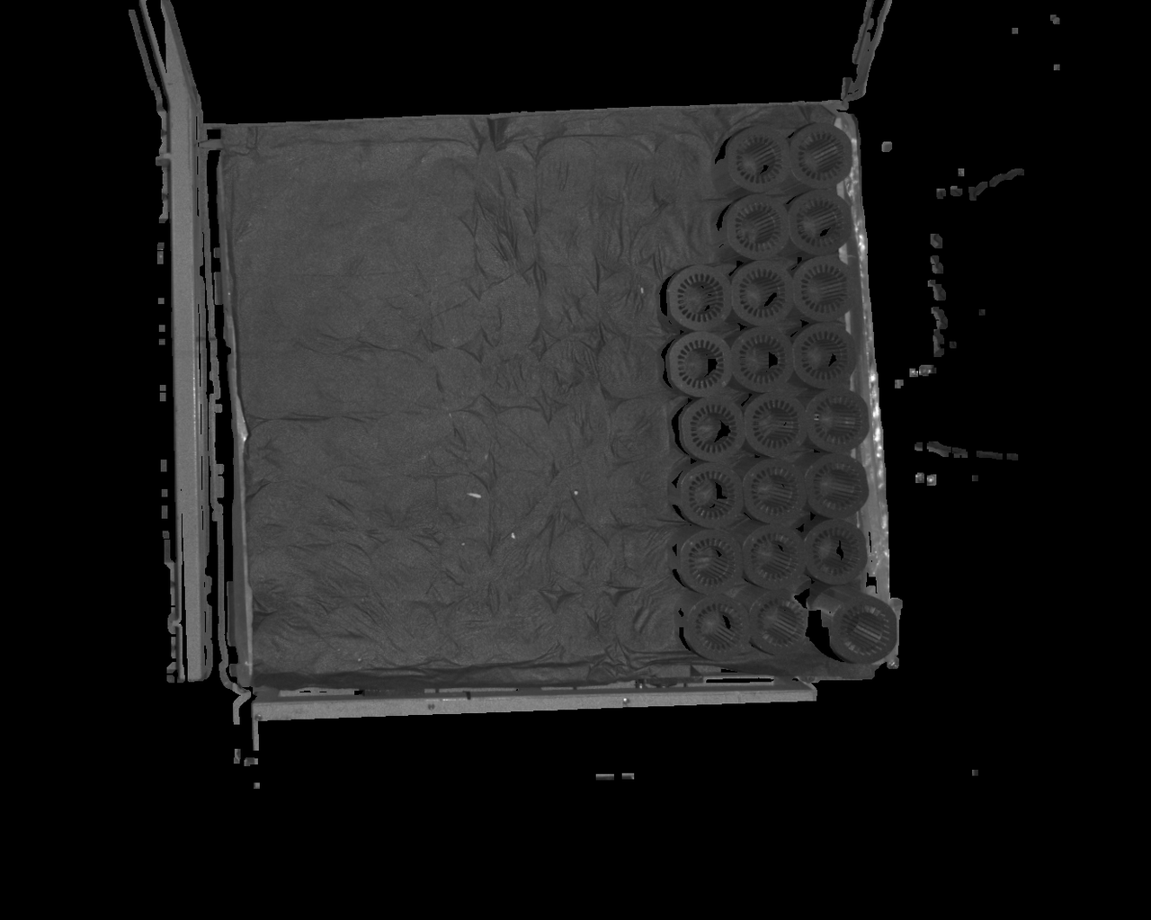 | 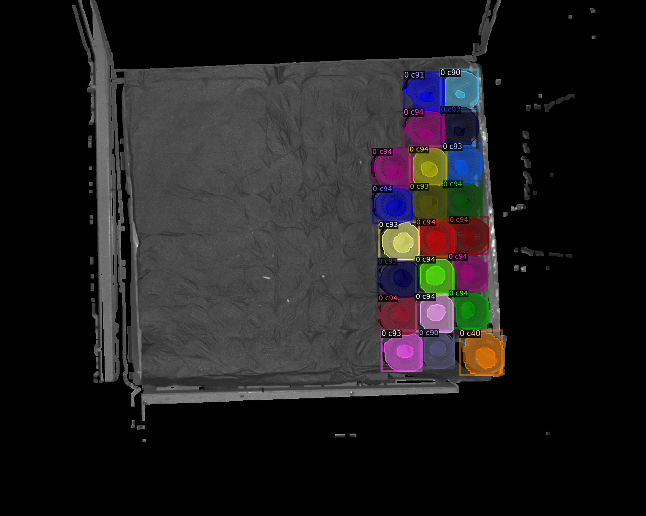 |
| 9 | 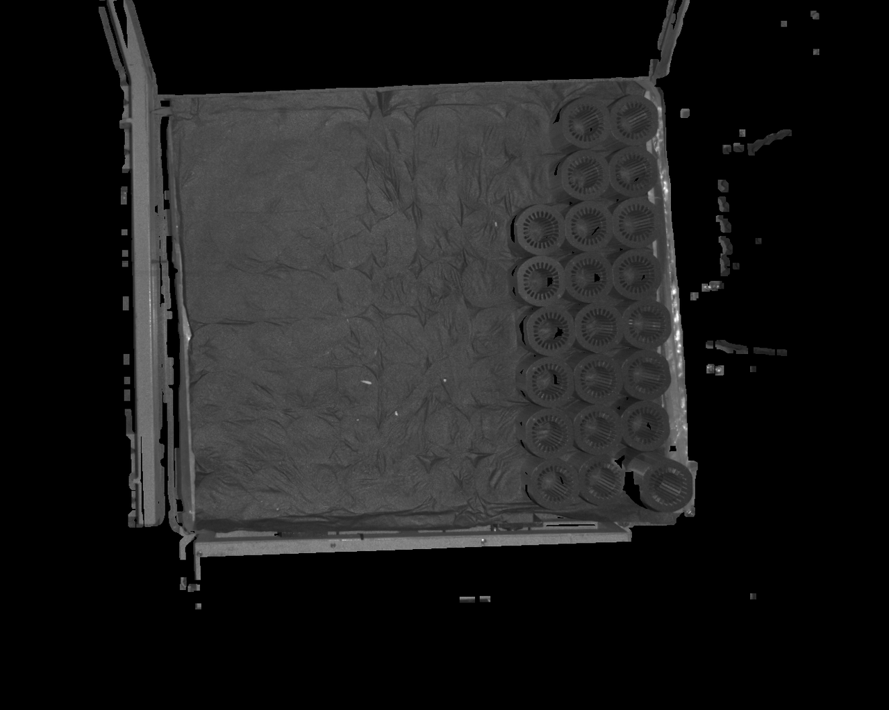 | 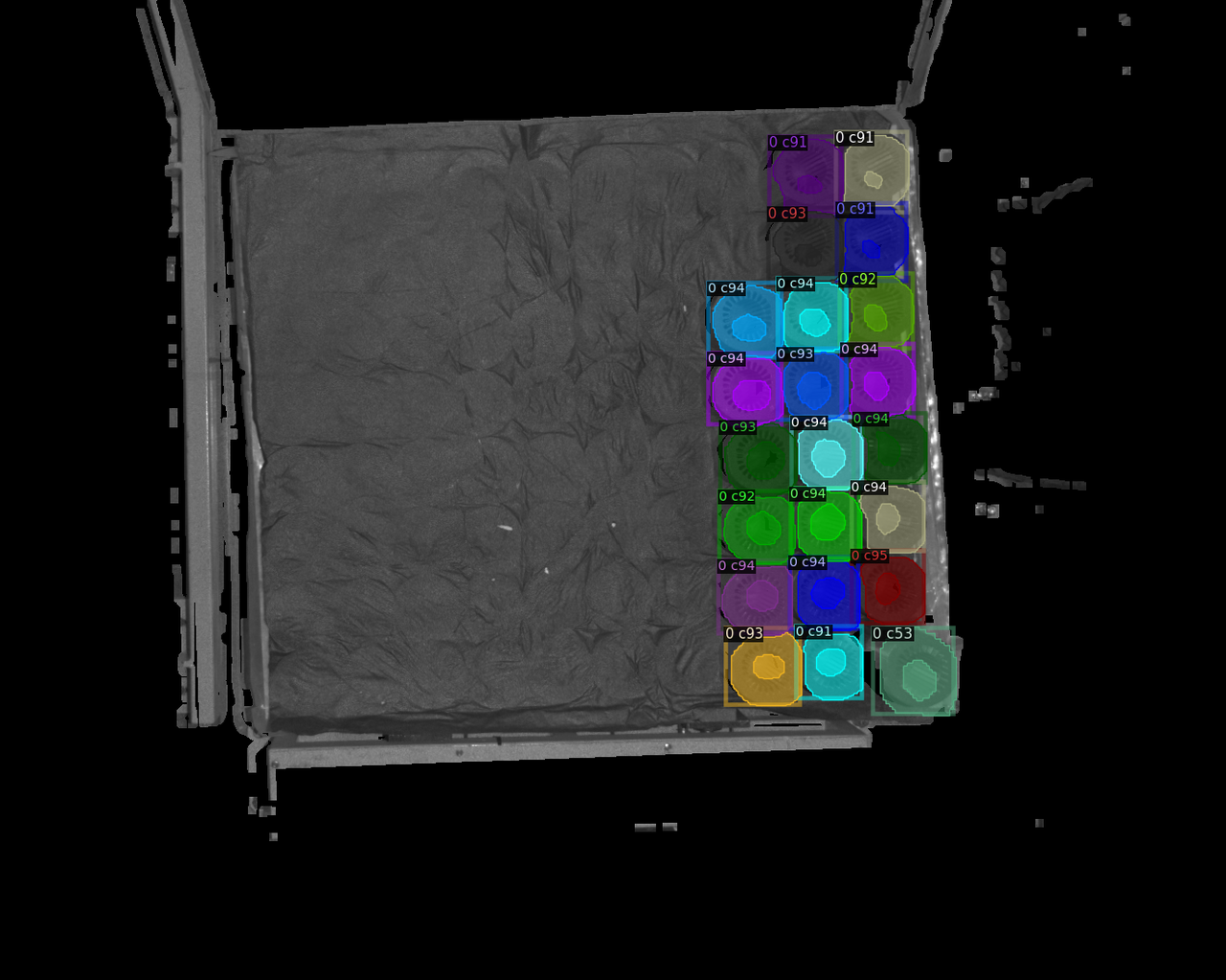 |
| 11 |  | 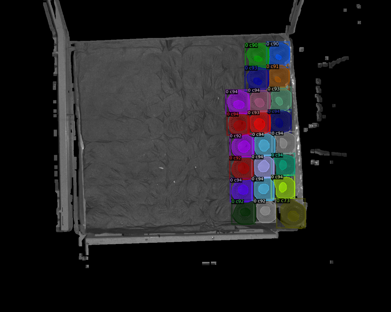 |
| 13 | 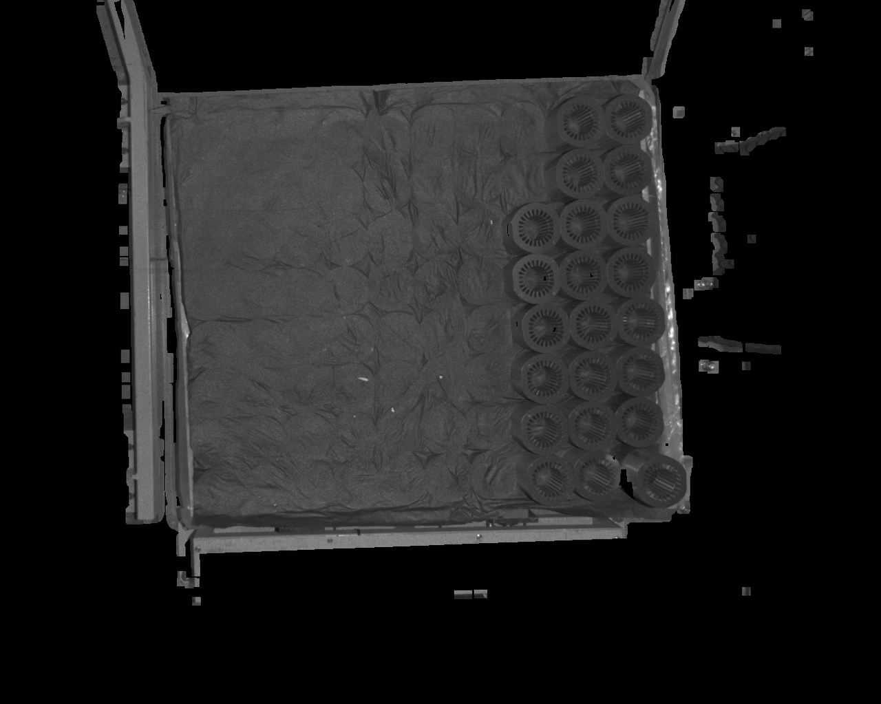 | 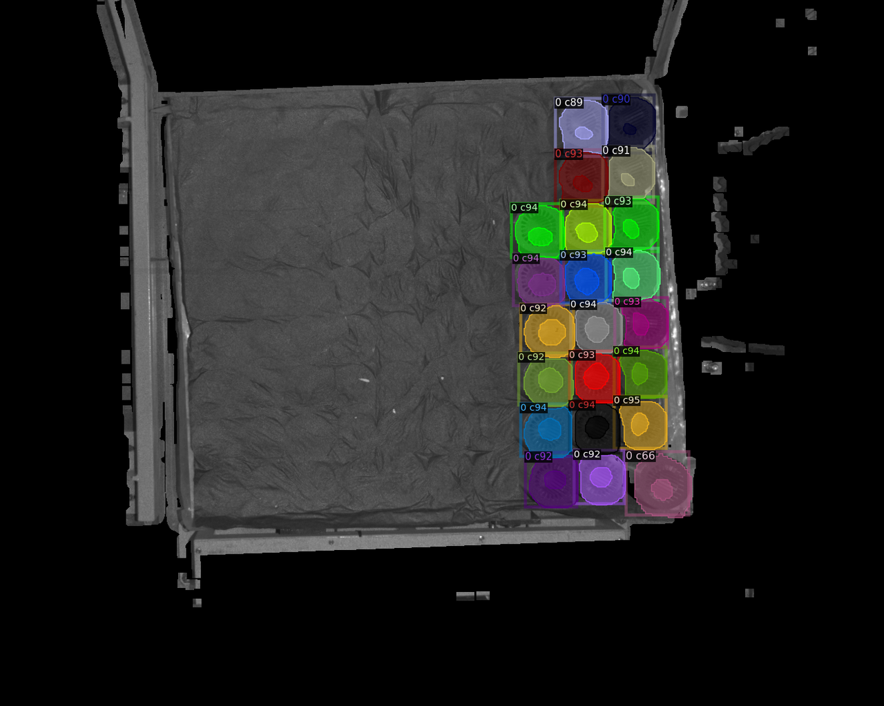 |
| 15 |  | 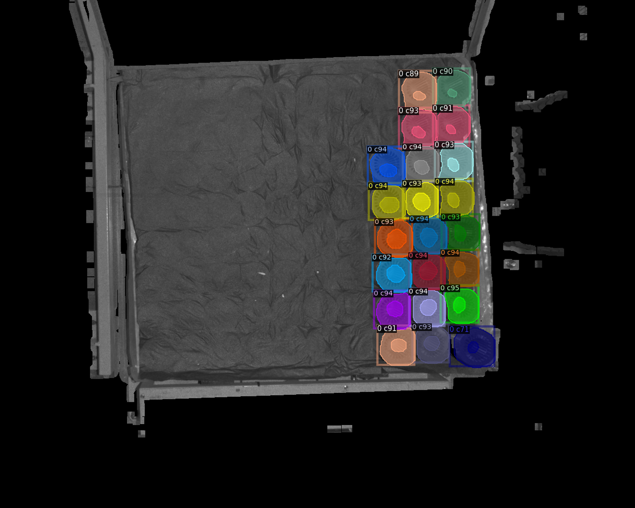 |
| 17 |  | 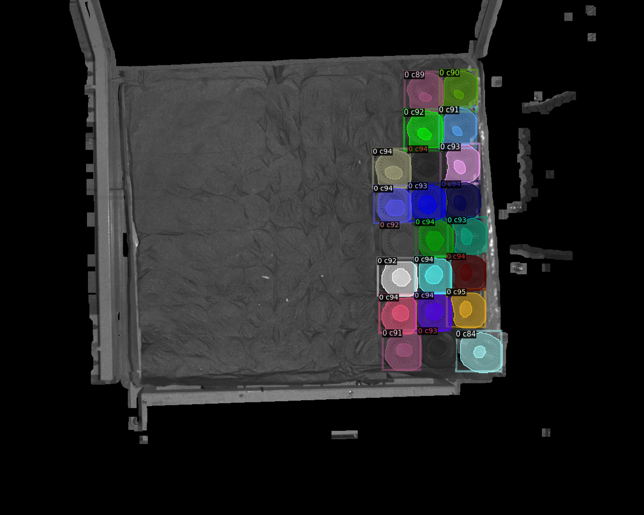 |
| 19 | 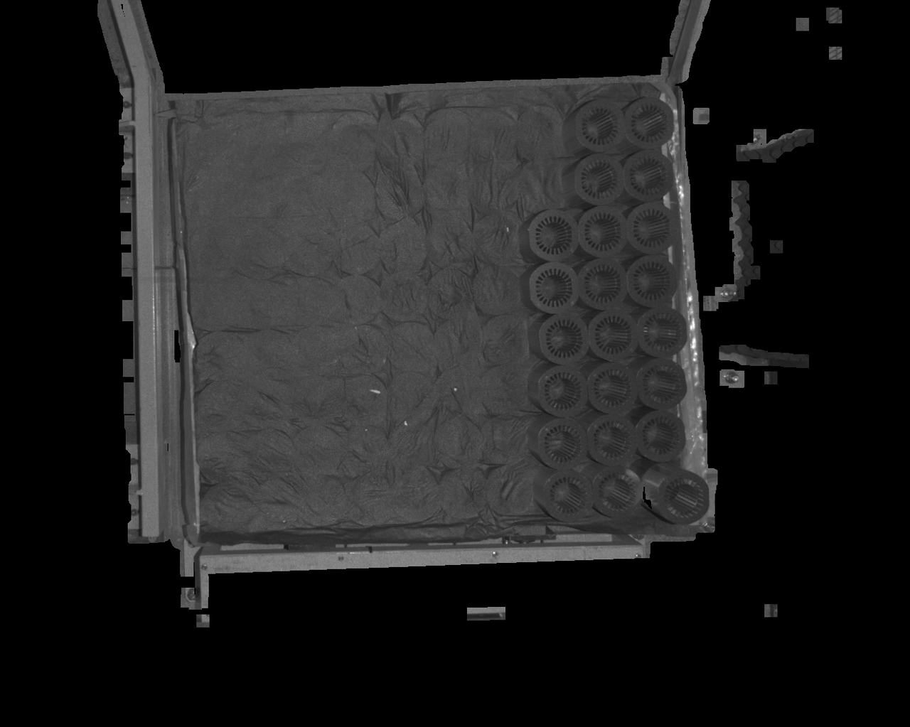 After increasing the fill kernel size, the black holes in the detection area are clearly reduced, and detection performance improves After increasing the fill kernel size, the black holes in the detection area are clearly reduced, and detection performance improves | 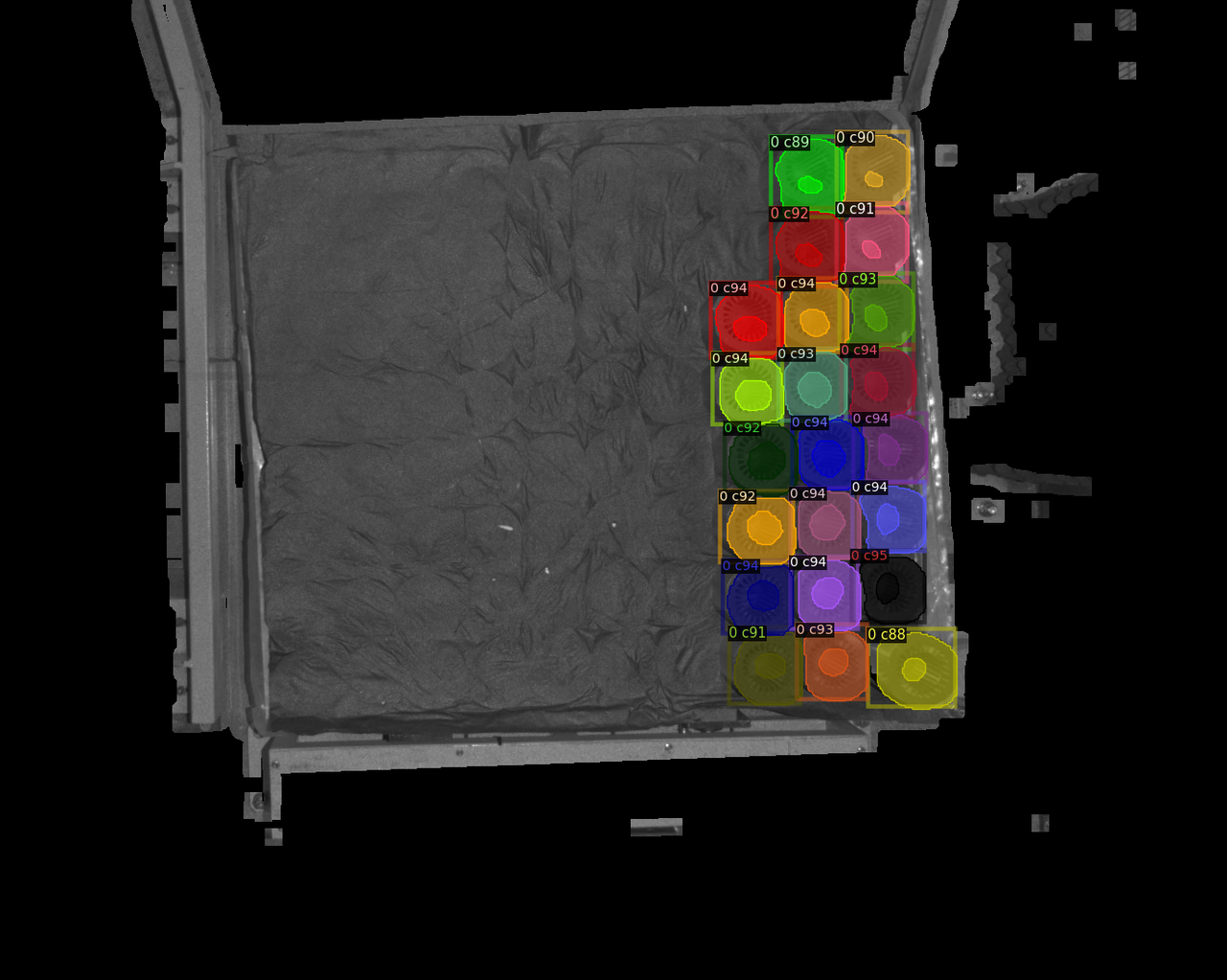 |
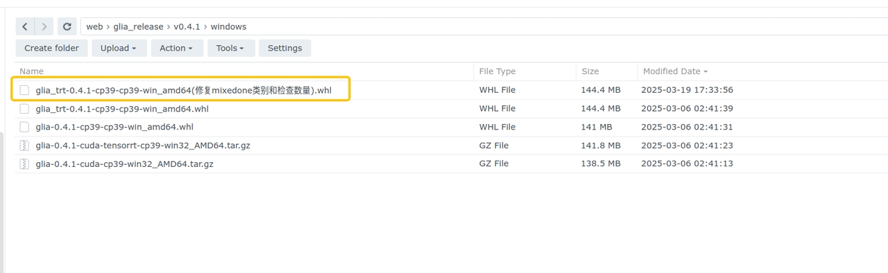
4.1.9 Model not recognized
Issue: When picking the last remaining layer of workpieces, the Deep Learning model cannot recognize them
Affected version: 1.6.1
Possible cause: The glia version is glia 0.4.1, which is not compatible with the model
Solution: Download the fix package from the NAS system. After updating the glia version, the model can recognize the last layer
4.2 CPFV
Surface Workpiece Vision Parameter Tuning Guide
4.2.1 No CPFV detection result
Issue: Detection failed. CPFV has no detection result.
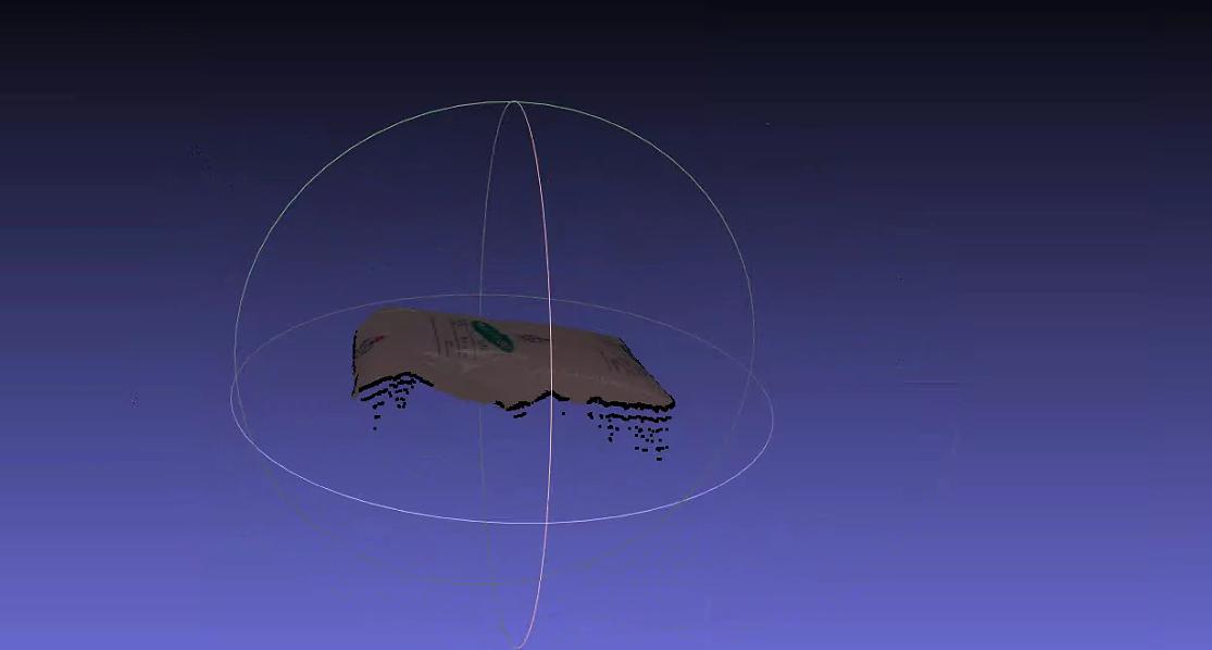
Solution:
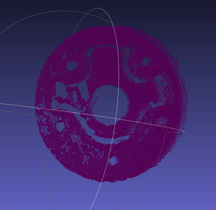
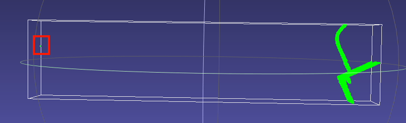
Check whether there are noise points unrelated to the main body in the template Point Cloud. The viewing method in meshlab is shown below. If the bounding box is larger than the expected template Point Cloud, it indicates that undeleted noise exists
When prompted that no pose was detected, first focus on the
bootstrap_percentageparameter. Set it to 1. Once matching is accurate, then consider reducing cycle time through parameters such as downsamplingCheck whether the order of magnitude of the template Point Cloud matches the scene instance Point Cloud (
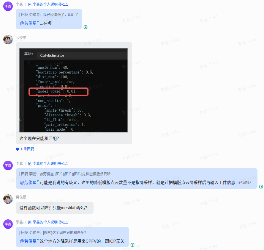
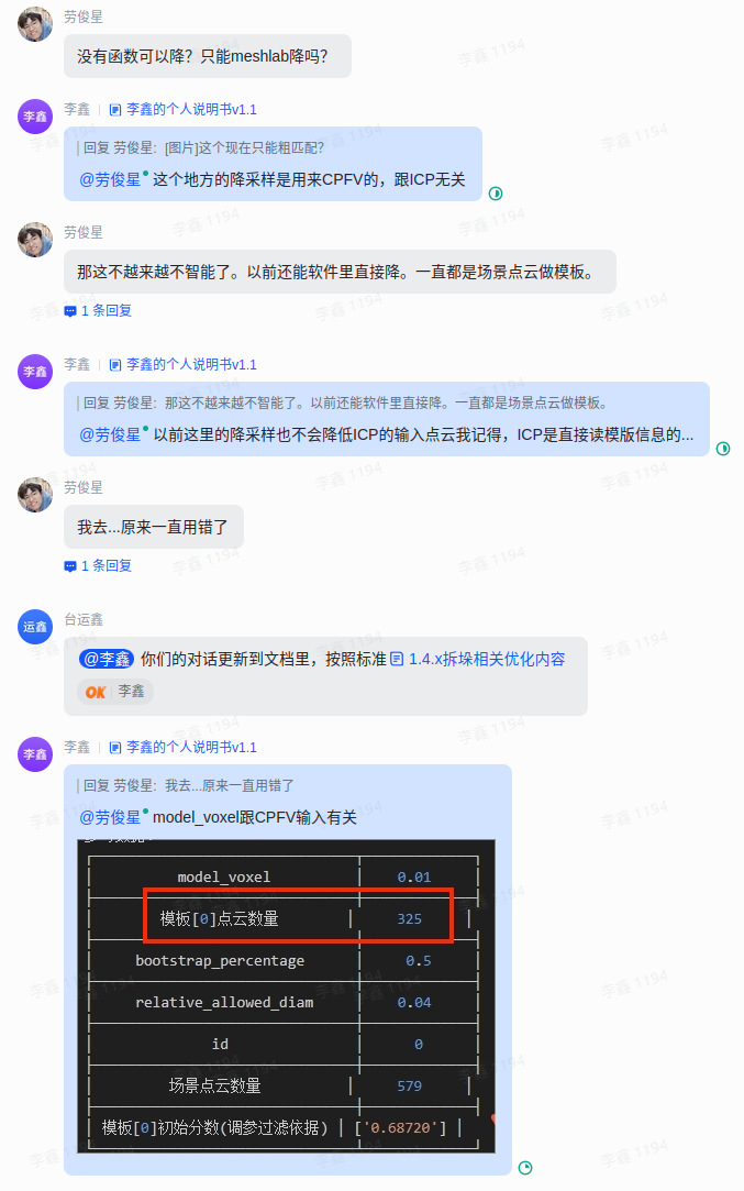
instancepcd) before downsampling (it is recommended to use the undownsampled scene Point Cloud as the template Point Cloud; when the scene Point Cloud is downsampled, the input Point Cloud for pose estimation should also be downsampled accordingly)Check whether the
model_voxelparameter is consistent with the scene Point Cloud downsampling parameter in preprocessingTry lowering both
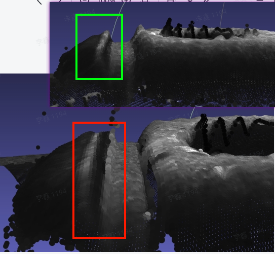
model_voxeland the scene Point Cloud downsampling parameter in preprocessing to increase the number of matchable pointsWhen the downsampling of the template Point Cloud and scene Point Cloud is consistent, and both Point Cloud counts are still 200+, but detection still fails, the issue may be due to differences in Normal between the template Point Cloud and scene Point Cloud (mainly possible when using contour mode, and fixed in version 1.5.2). You can open meshlab and load the Point Clouds to check the consistency of Normals between the template and instance Point Clouds. If the Normal consistency is high but detection still fails, contact product/R&D support
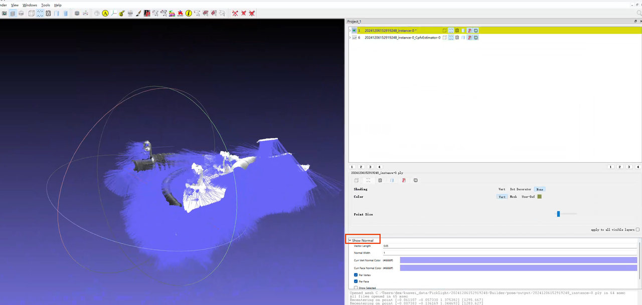
How to view Point Cloud Normals in meshlab
Load the Point Cloud
Select the Point Cloud whose Normals you want to view, then click
renderin the upper left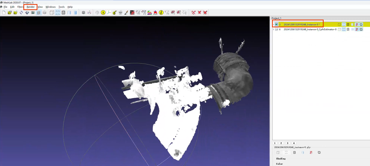
In the
renderdropdown list, clickshow normal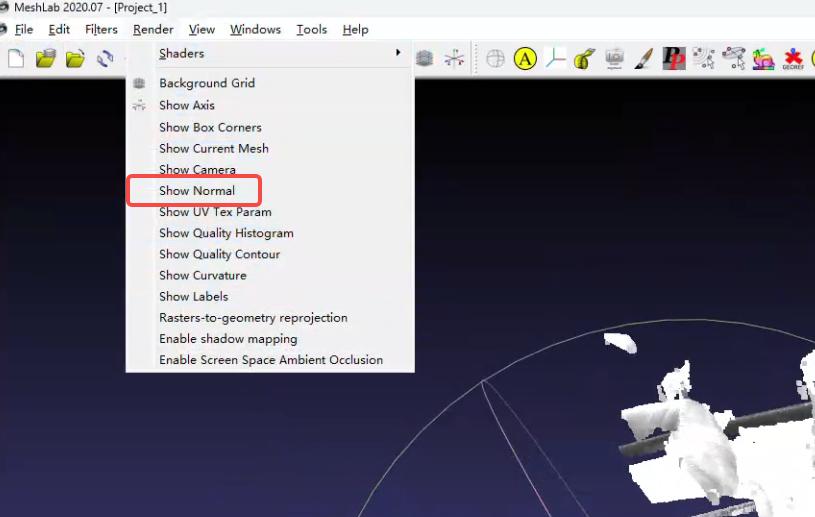
The color size can be set in the lower right
4.2.2 Poor model localization accuracy / poor repeat localization accuracy
Problem: Accuracy is poor. Model localization accuracy is poor / repeat localization accuracy is poor
Solution:
When matching is inaccurate, first focus on the
bootstrap_percentageparameter. Set it to 1. Once matching is accurate, then consider reducing cycle timeCheck whether a direction prior is set, and test whether disabling the direction prior is effective
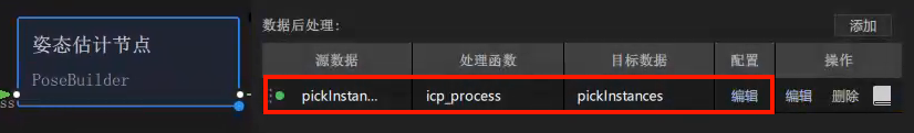
In backend PickLight versions after 1.4.0, CPFV does not perform ICP fine registration by default. Check whether the
icp_processfunction exists in the post-processing of the pose estimation node. For how to use the function, refer to Surface Workpiece Vision Parameter Tuning GuideSoftware version <= 1.4.2, note! When the
icp_processpost-processing function exists, to view the pose estimation result you need to enable theicp_processparameter"save_data": trueand inspect it in thepose_refinefolder. In other words, the Point Cloud registration result in the existing Pose folder ≠ the final pose estimation result, so you cannot determine that pose estimation is inaccurate based on the Point Cloud at that locationSoftware version >= 1.4.3: ICP registration results are saved in the two Point Cloud files with the
poserefinesuffix in Pose/output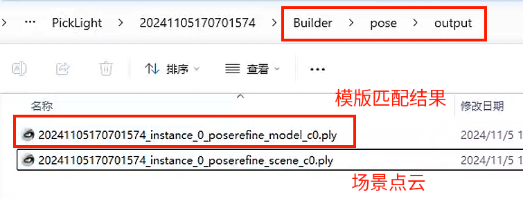
If the visualized accuracy result is still unsatisfactory after using the ICP function, you can try changing
icp_mode="Plane"in theicp_processfunctionWhen the localized object is small, reduce
icp_dist=0.xxxin theicp_processfunction according to the log promptWhen the same scene is photographed and matched multiple times but the results differ, check the consistency of the Point Clouds across the multiple captures (for example, whether multi-angle photography causes spatial changes in key feature regions of the Point Cloud)
Check and remove noise points in the Point Cloud template (parts that appear intermittently in the scene Point Cloud)
4.2.3 Rotation exists in model localization
Issue: Angle accuracy is poor / angle accuracy is required, and rotation exists in model localization
Solution:
When the workpiece is rotationally symmetric and consistent, rotation may cause
RZto rotate by 180 degrees. If the incoming workpiece orientation is always consistent, it is recommended to set the CPFV direction prior to[1,0,0,0]to maintain registration consistency. If the incoming workpiece orientation is not reliably consistent, then do not add a prior, and instead add and use thebound_euler_anglefunction. For the function description, refer to document 3.1 Grasping Strategy Tuning Guide【To Be Updated】"prior_direction": [[1,0,0,0]]
Add the
refine_pose_by_z_axis_rotationfunction in the post-processing section after the Pick Point generation node to correct the rotated pose (after 1.4.2)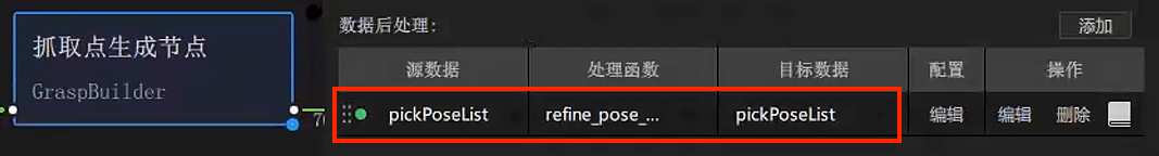
For the function Parameter usage, refer to Surface Workpiece Vision Parameter Tuning Guide
4.2.4 Registration cycle time does not match the expected cycle time
Issue: Poor cycle time. The registration cycle time does not match the expected cycle time
Note: CPFV cycle time is currently generally expected to be controlled within 2 seconds (1 second for detection, 1 second for fine registration)
Solution: On the premise that matching accuracy is acceptable, adjust the following parameters (it is recommended to test matching accuracy or check visualization results after each adjustment)
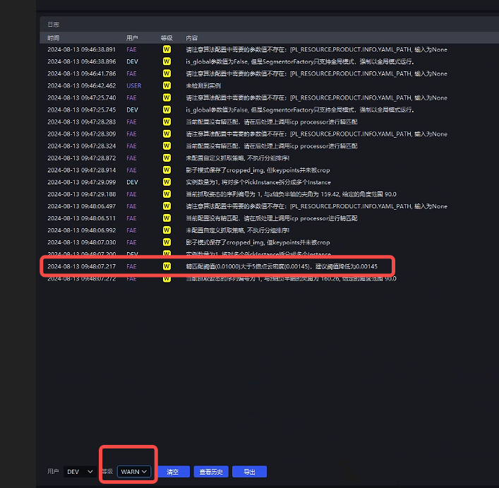
Check the detection time in the logs as shown below. The detection time represents CPFV runtime. Pose estimation runtime - detection time can be regarded as the post-processing ICP runtime

When CPFV runtime is high:
Adjust the downsampling parameters so that the number of template Point Cloud points and scene Point Cloud points in the reference data is around 200, which gives better results
bootstrap_percent5age0-1, speed: 1 is the slowest, 0.1 is the fastest; stability: 1 is the best, 0.1 is the worst; it is recommended to reduce by 0.1 each time, and in general the minimum should be adjusted to 0.3-0.5. If it is too low, occasional missed pose detections are likelyCheck
relative_allowed_diamParameter = 0.04
When post-processing ICP runtime is high:
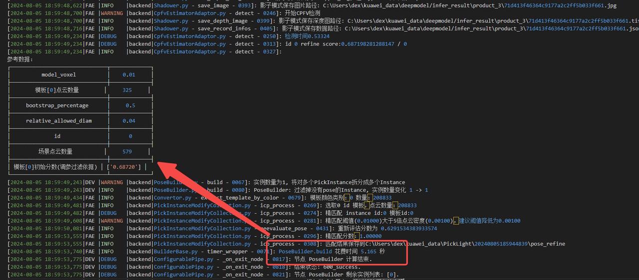
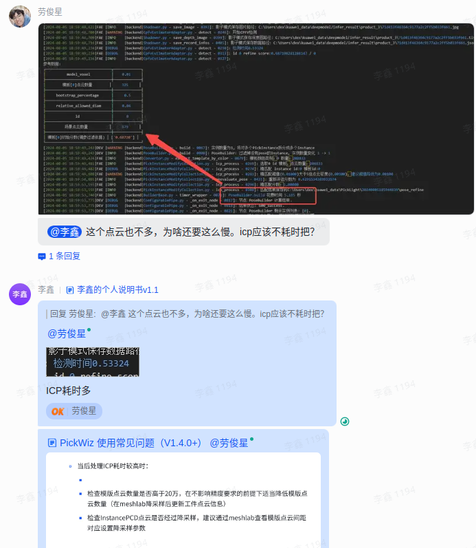
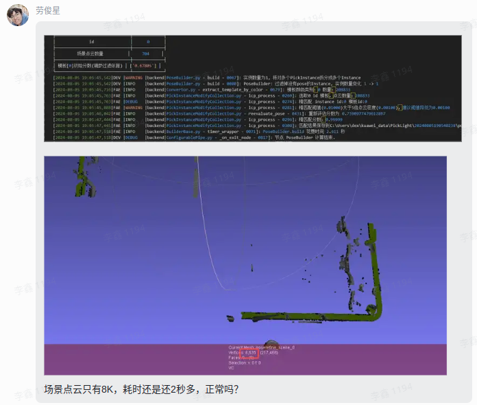
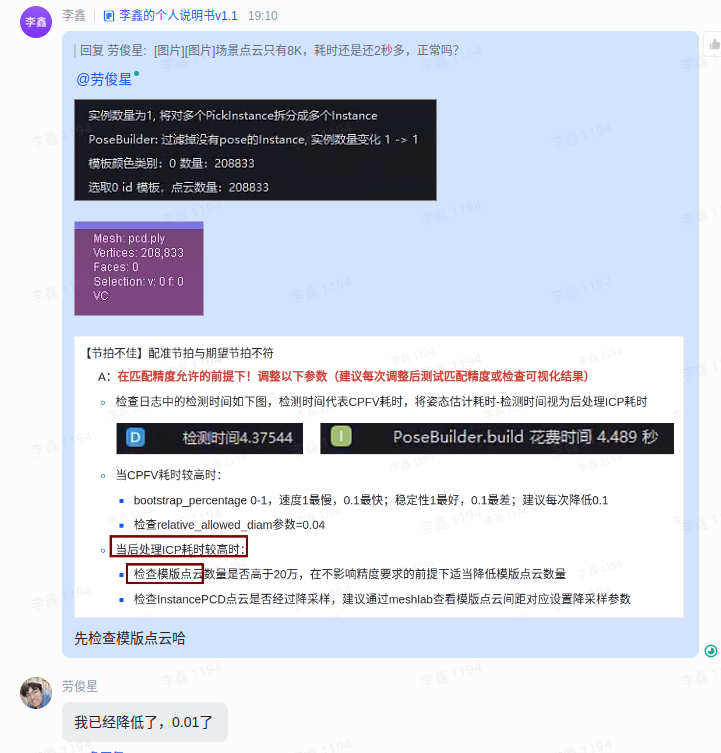
Check whether the number of template Point Cloud points is higher than 200,000. Without affecting accuracy requirements, appropriately reduce the number of template Point Cloud points (downsample in meshlab and then update the workpiece Point Cloud information)
Check whether the InstancePCD Point Cloud has been downsampled. It is recommended to use meshlab to inspect the template Point Cloud spacing and set the corresponding downsampling parameters
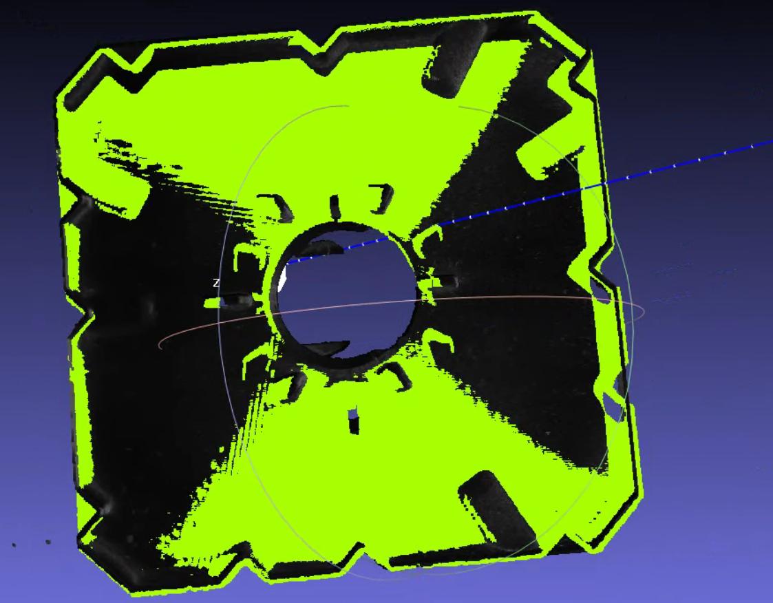
4.2.5 Flat workpiece matching produces offset sliding
Issue: Matching offset. Flat workpiece matching produces offset sliding
Solution: First confirm whether the dimensions of the target Point Cloud will change in each direction. If they do, you need to confirm the unchanged part of the main body
Use the template shown in the figure, and fill in the coarse registration template in the workpiece properties
Add the
icp_processParametermode_path="fine_registration_template_file_path"- For Windows paths, double backslashes or forward slashes are recommended
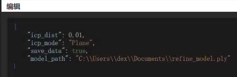
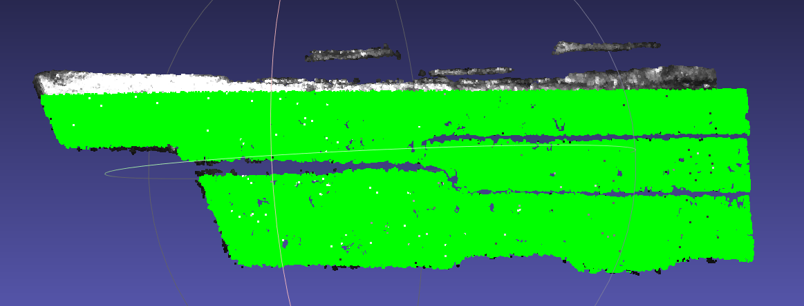
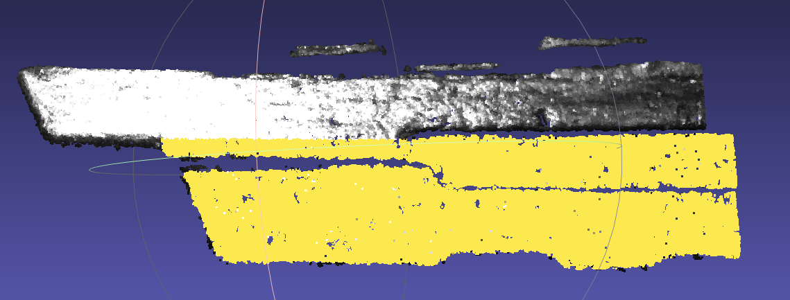
{
    "icp_dist": 0.01,
    "icp_mode": "Plane",
    "save_data": true,
    "model_path": "C:\\Users\\dex\\Documents\\refine_model.ply"
}
Scene Point Cloud (the dimensions inside the red box will change) Coarse registration template (the right side is recommended to be larger than the scene) Fine registration template (take the unchanged region) 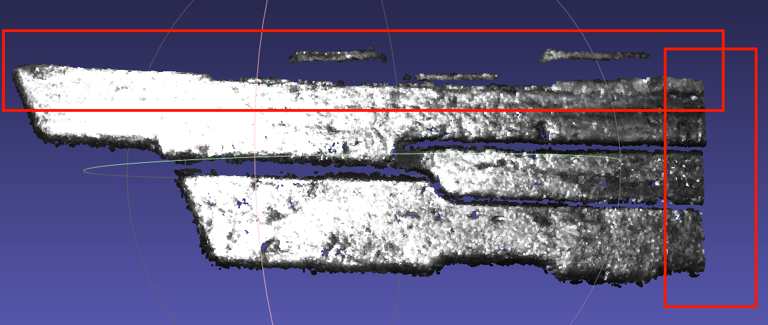
Add extraction of boundary points
Add the function
get_boundary_pointsin cpfv preprocessing{ "angle_threshold": 90, "max_nn": 30, "radius": 0.005 }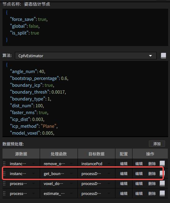
Warning! When using get_boundary_points, pay attention to changing the downsampling input data type
Add the
boundary_typetype to the cpfv parameters{ "angle_num": 40, "bootstrap_percentage": 1.0, "boundary_type": 1, "dist_num": 100, "faster_nms": true, "icp_dist": 0.01, "icp_method": "Plane", "model_voxel": 0.005, "nms_thresh": 0.5, "num_results": 1, "prior": { "angle_thresh": 30, "distance_thresh": 0.3, "is_flat": false, "pair_criterion": 1, "pair_mode": 0, "prior_direction": [] }, "process_in_roi": true, "refine": true, "relative_allowed_diam": 0.04, "scene_ratio": 1, "score_thresh": 0.5, "update_prior": false }When flat parts on site still show smooth offset after using
boundary_type, you can use the contour refine feature (currently exists in branchcwy/add-boundary-refine, and will later be merged into1.4.x). The usage is to add the parametersboundary_icp,boundary_threshParameter description:
When
boundary_icpistrue, contour refine is enabled. The default isfalseboundary_threshis the radius parameter used to calculate the model contour. The default value is0.005, the same as theradiusparameter in preprocessingget_boundary_points. (The contour radius parameter is recommended to be half of the downsampling coefficient, and should be adjusted according to the contour Point Cloud status of the template and scene inBuilder/pose/input){ "angle_num": 40, "bootstrap_percentage": 1.0, "boundary_type": 1, "boundary_icp": true, "boundary_thresh": 0.005, "dist_num": 100, "faster_nms": true, "icp_dist": 0.01, "icp_method": "Plane", "model_voxel": 0.005, "nms_thresh": 0.5, "num_results": 1, "prior": { "angle_thresh": 30, "distance_thresh": 0.3, "is_flat": false, "pair_criterion": 1, "pair_mode": 0, "prior_direction": [] }, "process_in_roi": true, "refine": true, "relative_allowed_diam": 0.04, "scene_ratio": 1, "score_thresh": 0.5, "update_prior": false }
4.2.6 Experience: debugging single-target precise positioning
Project name: Suzhou Samsung - Washing machine inner tub bottom screw hole positioning
Workflow characteristics
The Instance Segmentation node has no algorithm and only uses the ROI to frame part of the target workpiece area
It relies only on CPFV+ICP to register and precisely position the target
Project requirements
Positioning accuracy <=1 mm
Total runtime requirement <=2 s
Theoretical debugging process
First satisfy positioning accuracy, then consider reducing runtime. Refer to 【Detection failed】 and 【Poor accuracy】
It is recommended to first debug the Camera until the Point Cloud quality is stable, and then collect a scene Point Cloud dataset of different angle positions within a fixed ROI
Uniformly compare the scene dataset, confirm the feature region that appears 100% of the time, and select the relatively "3D" part in space as the Point Cloud template. If it is a flat workpiece, it is recommended to use contour registration
According to the log feedback in actual use, adjust the scene Point Cloud downsampling and CPFV+ICP parameters until the matching effect is stable
Test the repeat positioning accuracy. If it meets the conditions, end the positioning debugging; otherwise continue adjusting parameters
Accelerate CPFV+ICP on the basis that positioning accuracy meets the conditions
Refer to 【Poor cycle time】
If the pose estimation node is adjusted to about 1s but the overall runtime still exceeds expectations, refer to Algorithm process runtime analysis to analyze the cycle time, and then submit a request and consult product/R&D for other possible acceleration operations
Specific debugging issues and experience
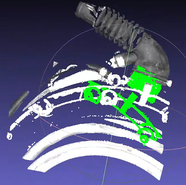
Issue 1: Matching offset + high runtime
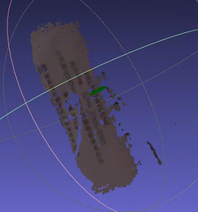
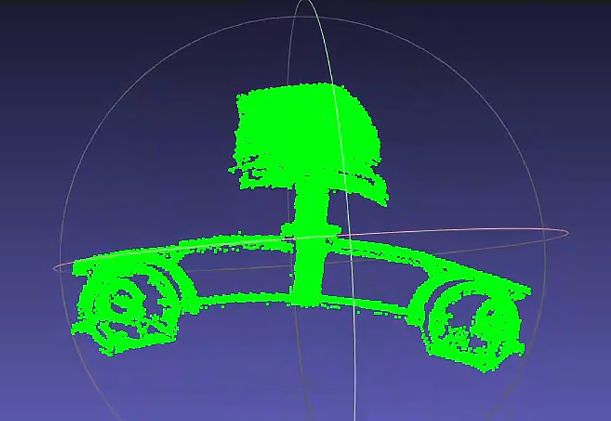
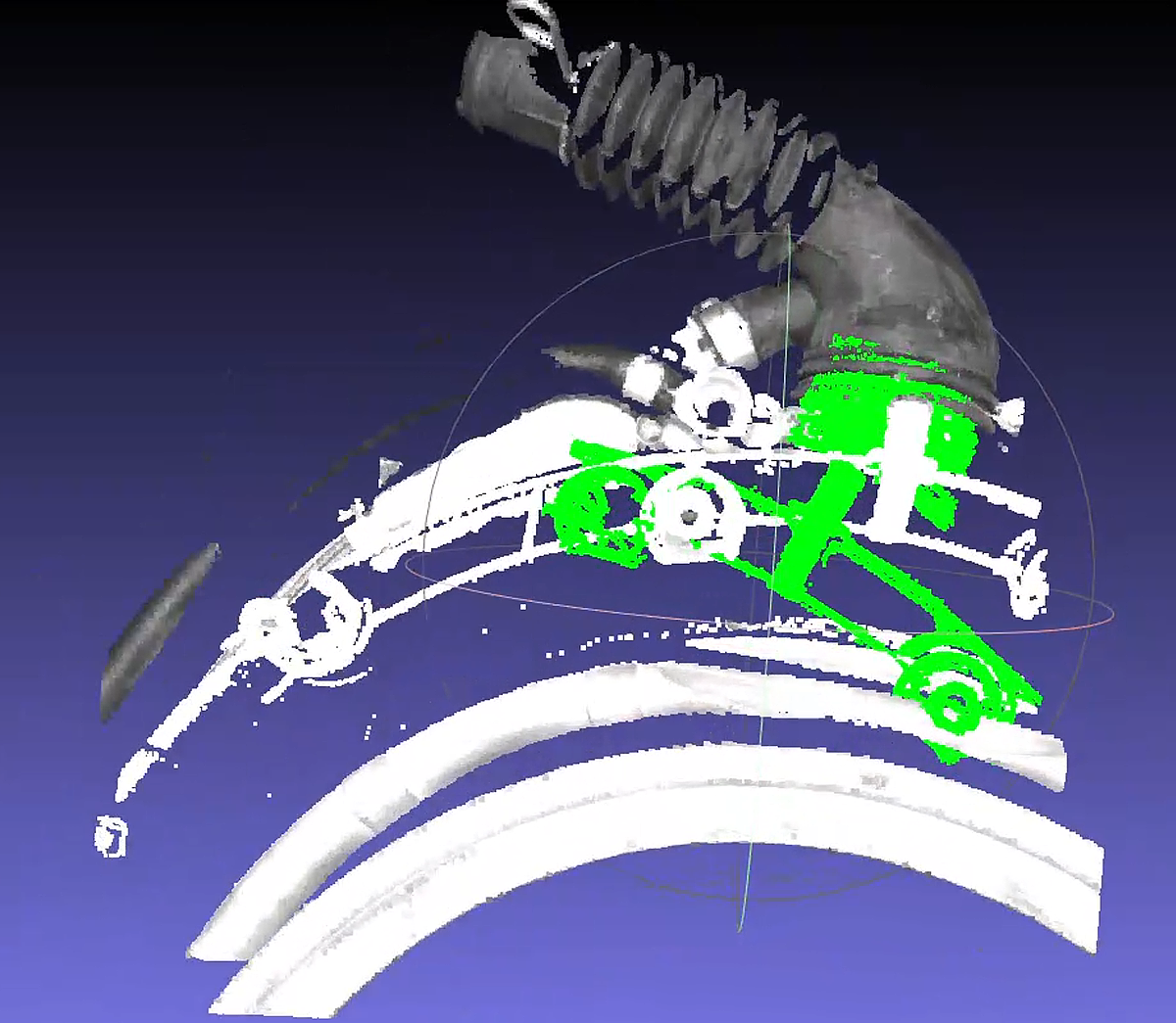
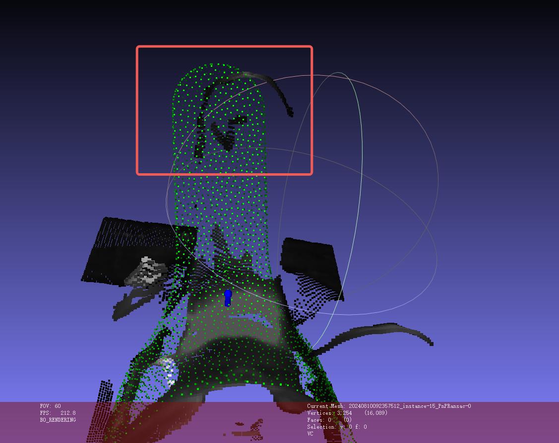
The on-site feedback on the pose estimation matching result is shown below. Green is the template matching result, and white is the scene Point Cloud
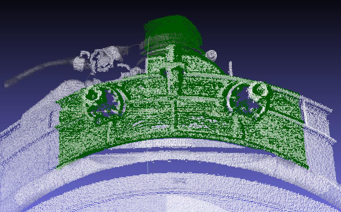
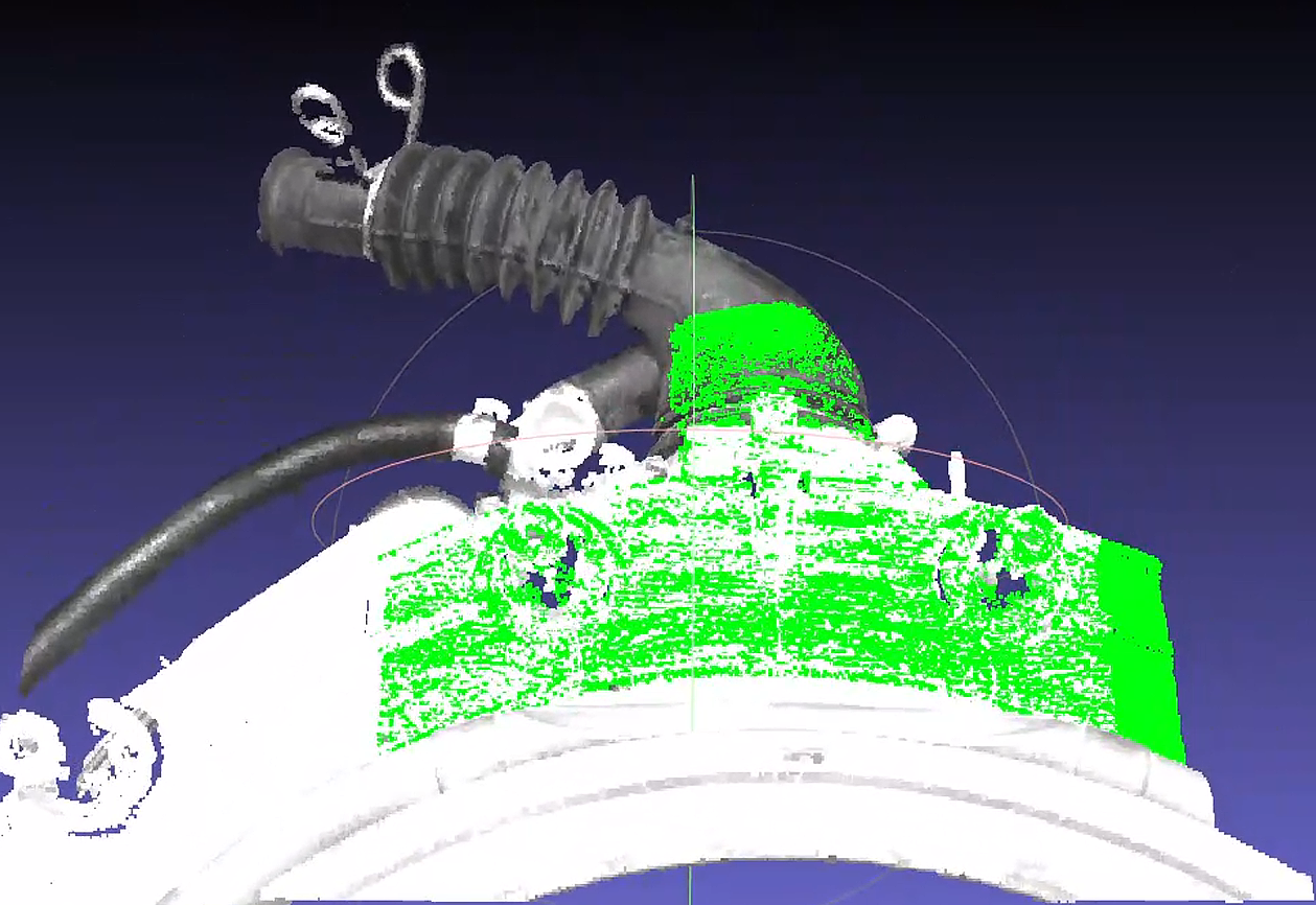
First, check the overlap between the template Point Cloud and the scene Point Cloud.
It can be seen that the main body of the pipe at the very top of the figure is largely missing in the scene Point Cloud.
The larger main body is the plane in the middle of the figure, and there are similar planar Point Clouds on both sides of that planar section.
Because the relative relationship between the ROI and the target is not fixed, the planar portion of the template on one side may extend beyond the scene Point Cloud.
Determine the cause of the matching offset.
Due to ICP's point-pair matching characteristics, a greater number of similar points can cause the head of the template T-shape to "sway" left and right at the scene Point Cloud position, while the pipe main body at the tail of the T-shape cannot be effectively "anchored" by the scene Point Cloud, resulting in possible deviation.
In addition, the
icp_disThreshold is set to0.01by default, causing the template Point Cloud to treat points within about10mmas "its own," which further increases the randomness of matching.
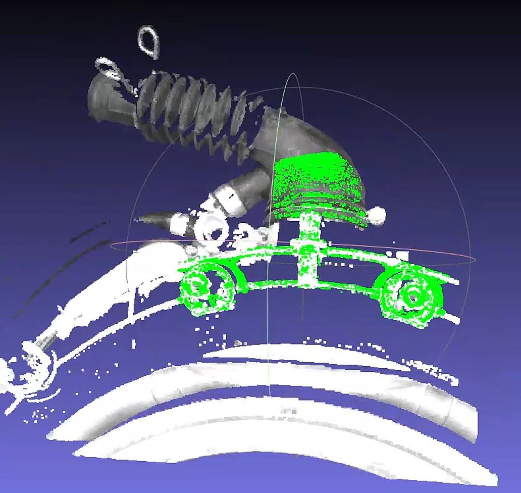
Solution 1:
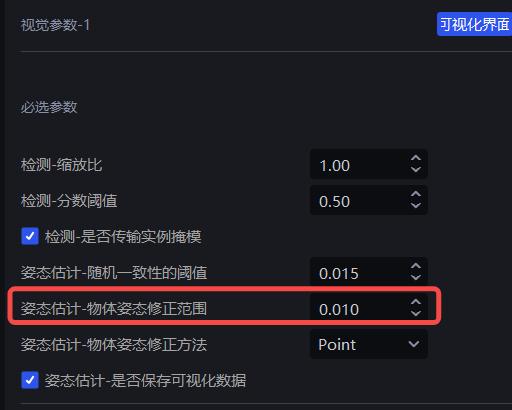
Set
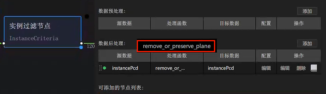
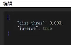
icp_dis=0.002to reduce the randomness of movement of the template Point Cloud.Adjust plane removal for the Point Cloud template, and add
remove_or_preserve_planein the post-processing after the instance filtering node to reduce the abnormal impact of missing planar regions on matching. The Parameter settings are shown in the figure. When actually creating it, there will be one extrareturn_paramsParameter; just delete it.Set
dist_thresaccording to the fluctuation thickness of the planar Point Cloud.When
inverseis set totrue, the plane is removed; otherwise, the plane is preserved.
Create a new template based on the Point Cloud with the plane removed.
Adjust CPFV and preprocessing downsampling parameters to improve speed. You can directly refer to 【Poor cycle time】.
Issue 2: Low repeat positioning accuracy in matching
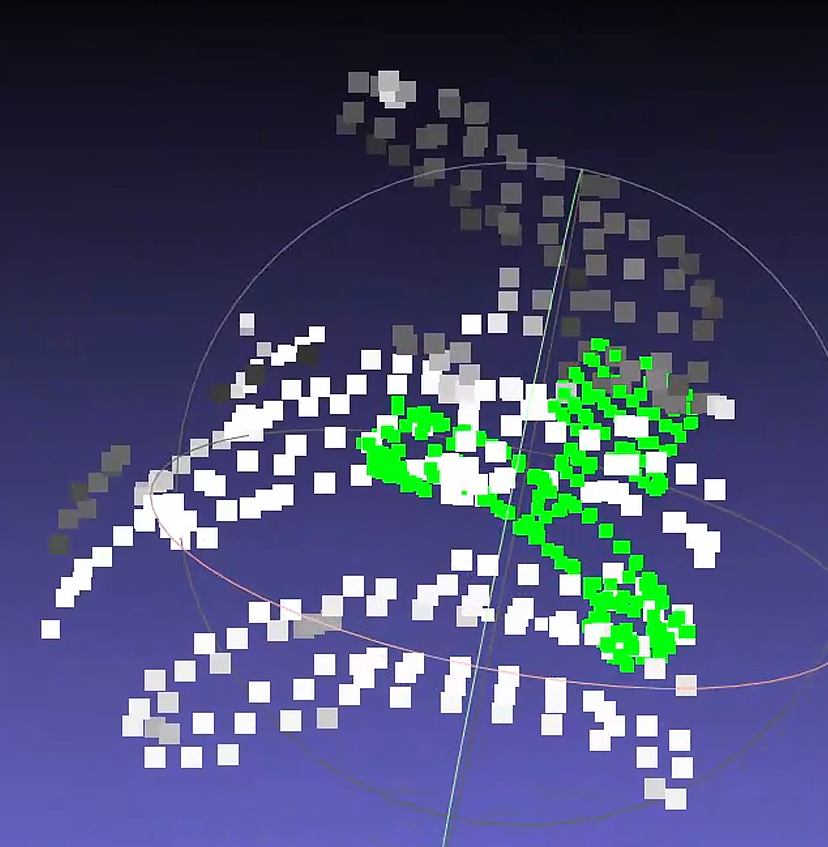
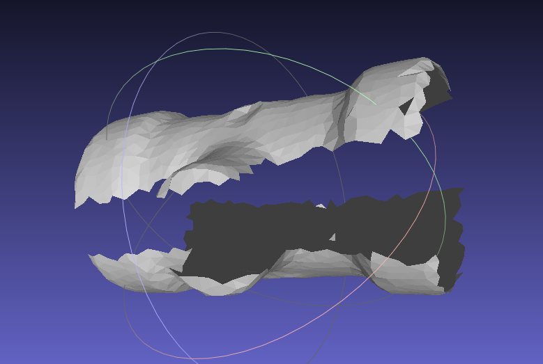
The pose estimation result is severely misaligned.
Check the coarse registration Point Cloud condition.
The CPFV coarse registration result of the new template may be poor, causing ICP to fail to produce the correct result.
It was found that there is a severe difference in point spacing between the template Point Cloud and the scene Point Cloud. Inspection showed a large difference between the parameters
model_voxel=0.01andvoxel_size=0.02.
Solution 2:
- Adjust the preprocessing downsampling Parameter to
0.015so that it is close to CPFV's"model_voxel"=0.01.
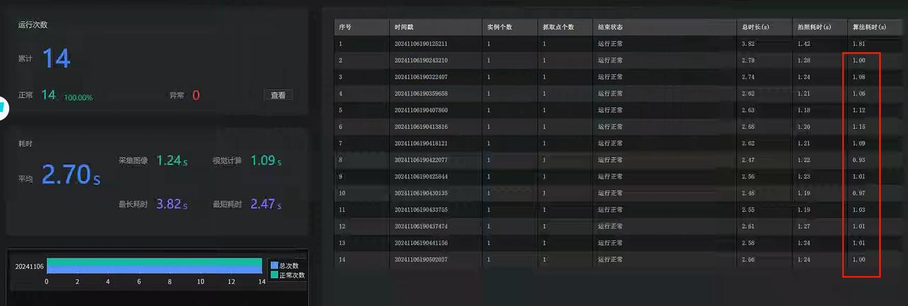
After correction, tests on 13 sets of historical data matched normally. At the site, the Camera was used to take 10 shots, and the repeatability met the requirements. The algorithm runtime was about 1s.
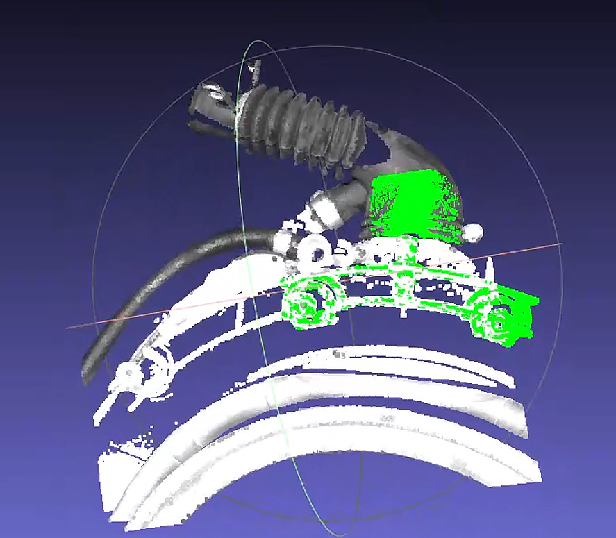
Notes
The main body in the new template has been changed from a plane to the front end of the black pipe, so it is still necessary to ensure that this part is always within the ROI regardless of the incoming part angle; otherwise, it may still cause matching deviation!
4.3 PNP
4.3.1 Inaccurate matching / reversed matching
Issue: Inaccurate matching / reversed matching occurs during the matching process.
Solution:
Check the template Point Cloud and delete interfering Point Clouds.
Check whether the template Point Cloud and the scene Point Cloud are exactly reversed by
180°. If so, flip the template Point Cloud by180°.
 |
  |
|---|
4.3.2 Matching offset
Issue: In random picking based on CAD, pose matching is offset when using the SpatialRansac algorithm.
Solution:
- Use surface workpieces + the cpfv algorithm, and obtain the model Point Cloud file by photographing with the Camera and extracting it.
If inaccurate matching still exists after using cpfv, refer to the following solutions:
Adjust Camera parameters to obtain high-quality Point Cloud images.
Process the Point Cloud image after Instance Segmentation and use it as the Point Cloud template.
Adjust the number of points in the template Point Cloud and the scene Point Cloud, and control the number of points between
200\~400.Adjust the
bootstrap_percentageParameter to1to remove the pose angle prior in pose estimation.
4.4 Cylinder fitting PMFE
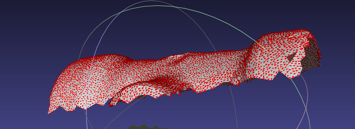
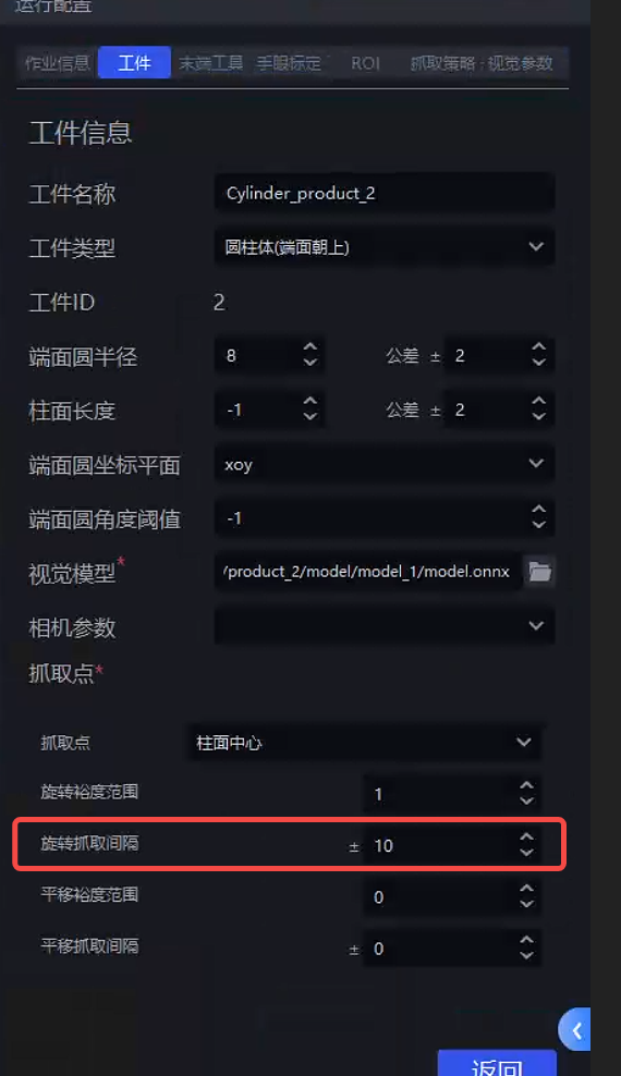
4.4.1 Pick Point angle not vertical
Issue: How can the Z-axis Pick Point angle be kept in a state that appears more vertical to the human eye?
Solution: Reduce the rotation interval in the cylinder workpiece properties so that there is one Pick Point every small angle around the cylinder surface. This makes the Pick Points denser, meaning the angle difference between the most vertical Pick Point and the ROI Z-axis or Camera Z-axis will be smaller, as shown below:
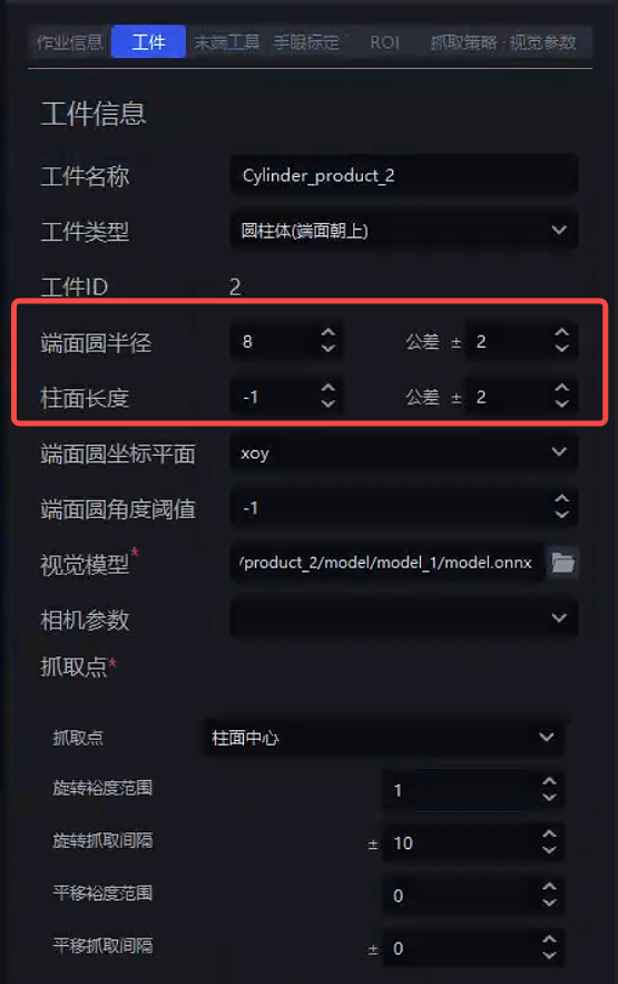
4.4.2 The fitted Pick Point is not at the cylinder center
Issue: How to ensure the Pick Point is at the cylinder center
Solution: Set the radius prior and length prior in the cylinder workpiece properties, as shown below (unit: mm)
4.5 Classification
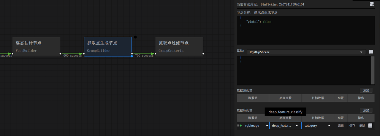
4.5.1 Add orientation classification for cylinders
Issue: How can a new cylinder orientation classification be added?
Solution: To create a new part, you need to add front/back orientation:
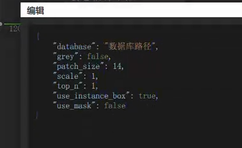
- Perform front/back classification on a single instance. First, add the processor
deep_feature_classifyin the post-processing after Pick Point generation, with the parameters shown below.
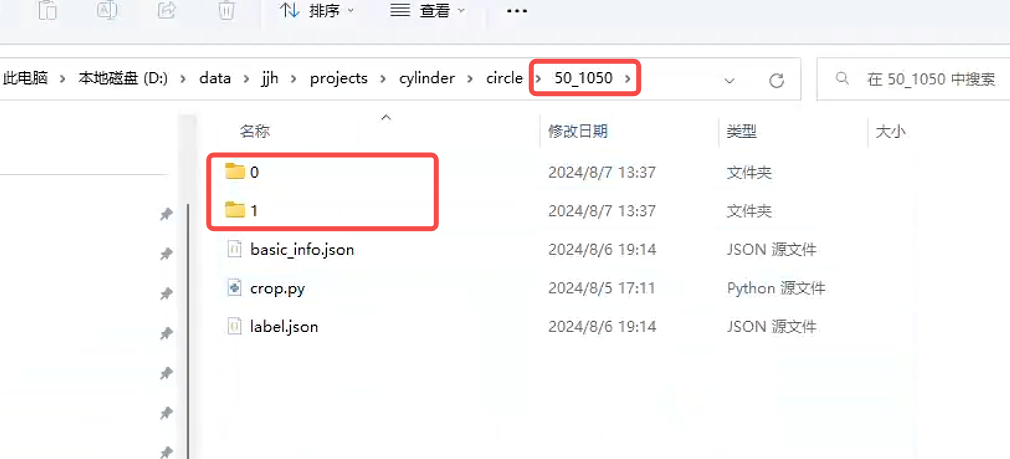
- Create a folder to store the front/back data, and under the created folder create two folders named
"0"and"1", as shown below.
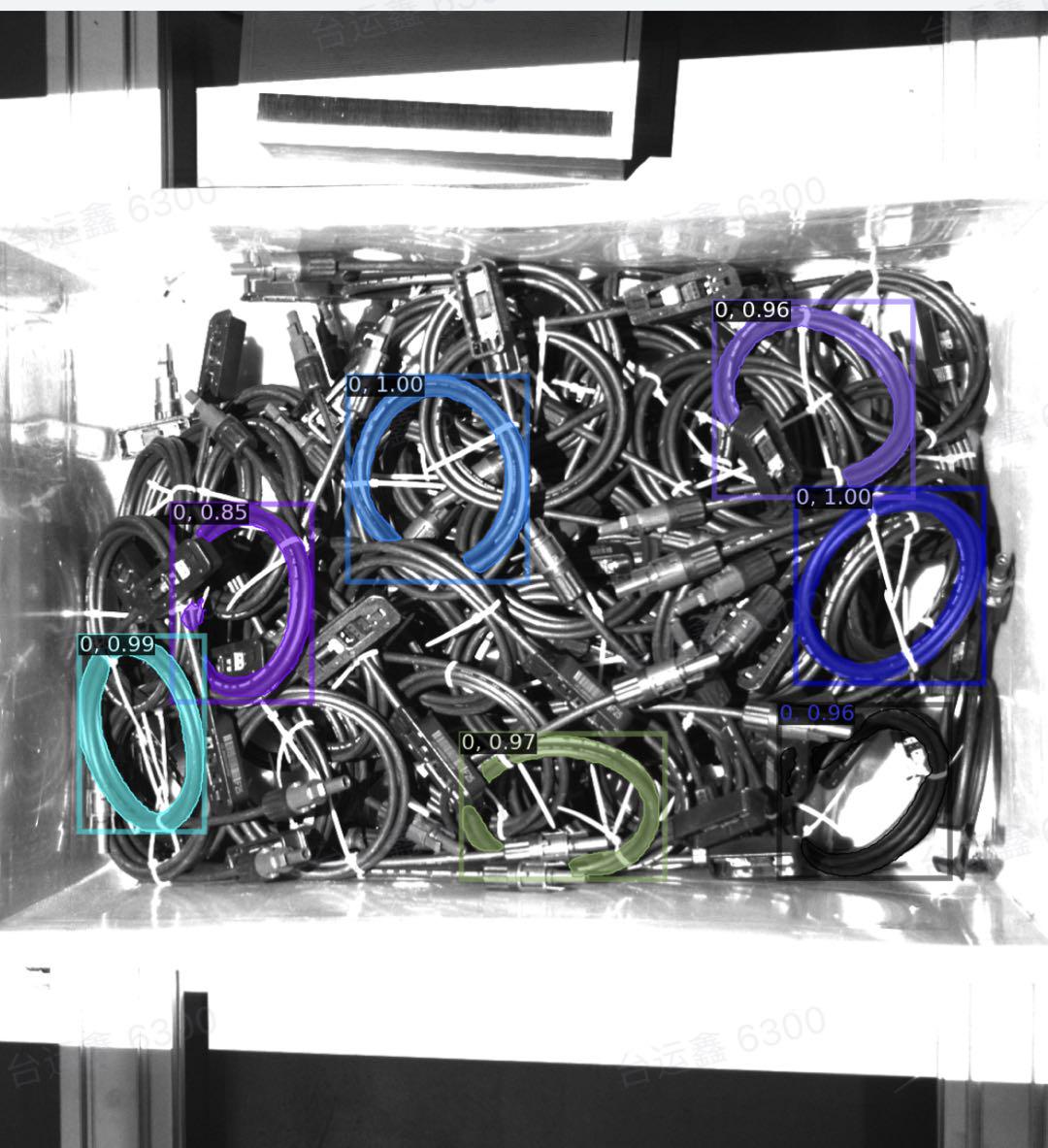
Then run the Workflow once. After
deep_featrue_classifyis called, it will automatically crop the front/back images and store them in the historical data.View the latest historical data in picklight.
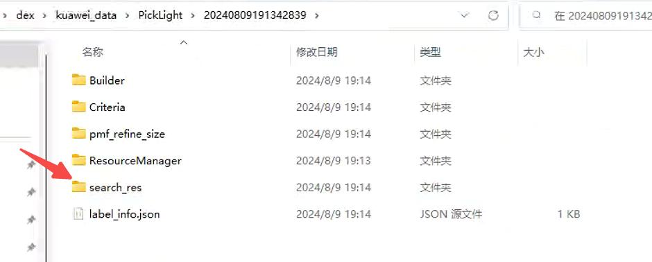
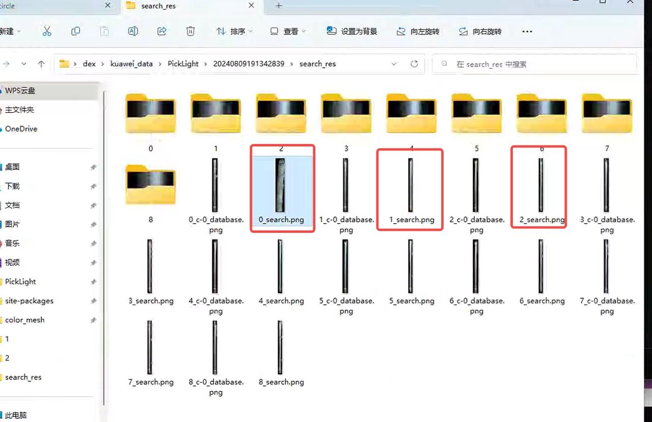
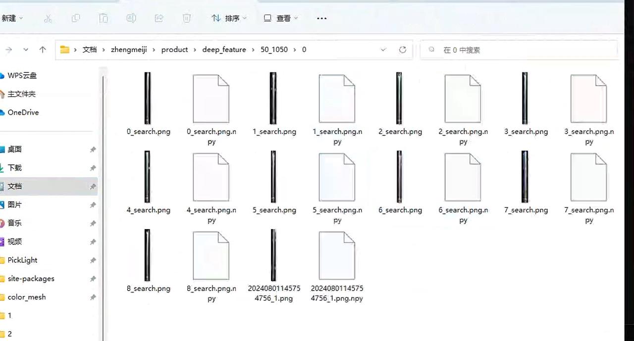
- Copy
x_search.png, then under the specified path create a folder named with the size of the part you want to add. The most direct way is to copy an existing folder and then clear its contents. Inside are the0and1folders. After clearing them, put in the images classified by orientation (Tip: in this step, the operator must distinguish the front and back by themselves).
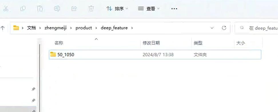
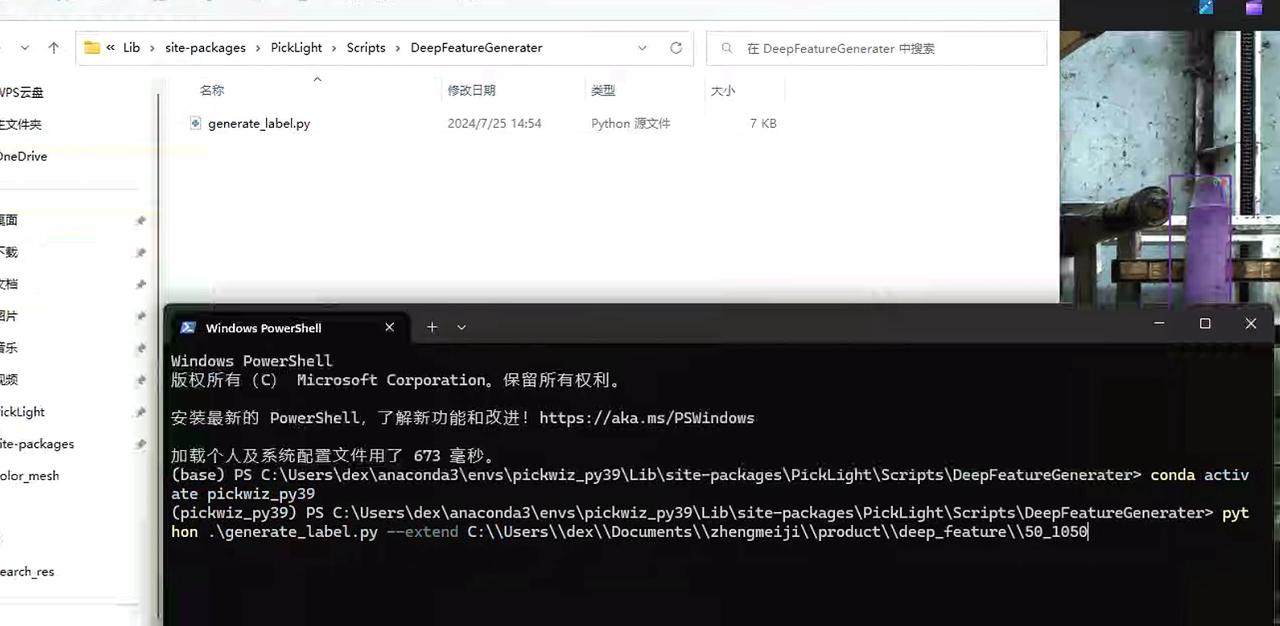
- Go to this path and execute these two commands. Remember to change the path to the part you want to add. In this way, the front/back templates will be created. (How to find the path: open the folder on the desktop named
New Folder 2, find the folder namedsite-packageson the left and click to enter it, then create the folder according to the path shown in the figure.)
- If you want to add a new part, just repeat this step starting from step 2.
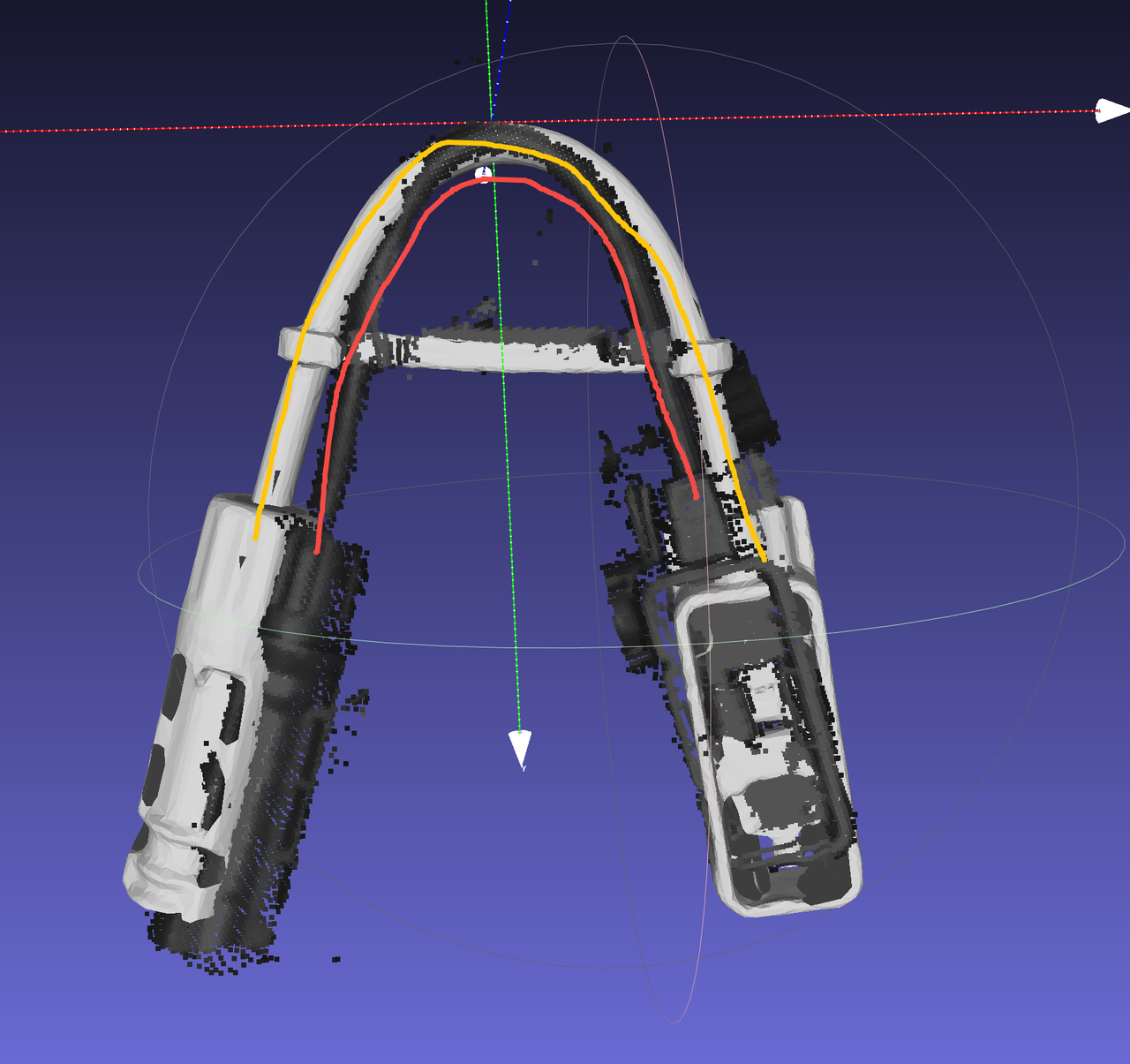
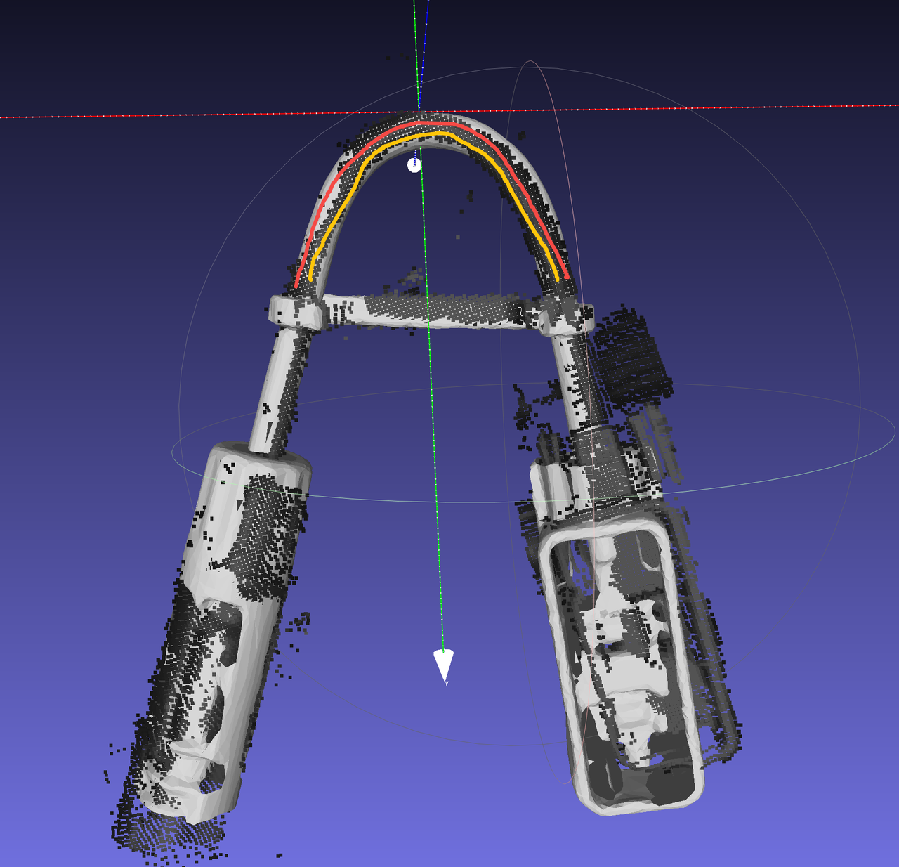
4.6 Wire harness Workflow
4.6.1 Camera configuration
Adjust the 2D exposure. The exposure needs to be high enough so that the wire harness does not appear "completely black."
4.6.2 Workpiece template
Use the extracted Point Cloud as the template, and align it with
keypoints,mesh, etc. This can be done using meshlab.O-shaped wire harnesses generally have dimensional differences. You can scale both the Cad and the feature points at the same time; refer to Common Meshlab Operations, form a model with dimensions equivalent to the actual wire harness, and register it into the software.
4.6.3 Bin detection
Extract the bin opening, and refine the extraction of the bin opening.
Keep the Point Cloud storage path well managed; bin templates for different workstations are independent of each other.
In the backend logs, pay attention to
backend.logand search for "container score" to check whether the matching score is normal (generally it should be above0.3-0.4).Use
Pointsfor the matching mode.If the material has not passed the bin opening, note that additional handling is required.
In the
outputof thecontainernode, the item with theicpsuffix indicates the final bin opening matching result;initindicates the initial bin opening pose.
For detailed usage documentation, see Circle3D, IcpEstimator and CPFV Parameter Description
4.6.4 Pose estimation
In the wire harness scenario, use
Pointsfor the matching mode.After changing the Camera exposure, be sure to change the Processor as well, because there may be color filtering that causes abnormal Point Cloud filtering.
The runtime branch for the wire harness is the specific branch
cwy/collection_add_collision_score(only for version1.2.x; version1.4.xdoes not require this). To prevent an empty bin report during mid-process picking,fitnessneeds to be set to0.
4.6.5 Collision detection
Special handling is required when configuring the gripper; otherwise, it is easy to encounter the "gripping the bin wall" phenomenon.
The bin height setting must be reasonable; otherwise, "false collision detection" can easily occur, causing the materials at the bottom of the bin to become ungraspable.
When the gripper scrapes the edge of the bin, it is recommended to determine whether the root cause is a positioning issue or a gripper size issue. The gripper can be expanded. For the method, see Common Meshlab Operations.
4.6.6 No Pick Point
4.6.7 Pick Point settings
For the
xandyaxes, the gripper coordinate system needs to be set at the center of the wire harness Point Cloud.The
zaxis needs to be set on the surface of the Point Cloud; it must not be too high or too low.The
rzangle needs to be adjusted correctly to match the actual grasping pose.The
rxandryposes need to be set perpendicular to the Point Cloud.In the case of an eccentric gripper, collision detection filters out more candidates, so symmetric Pick Points need to be set to avoid collision detection.
4.7 Pick sorting
4.7.1 Sorting abnormality: not picking in the expected order
Solution:
- Check whether the instance filtering function has taken effect and reduced the number of instances participating in pick sorting. All instances need to be sorted to obtain the correct pick order.
4.7.2 Grasping strategy: picking the lower layer
Solution: Troubleshoot step by step.
Based on the visualization of the instance generation node, determine whether the upper-layer instances have been segmented correctly.
Confirm at which node the instance Point Cloud is generated; the height-sorted grasping strategy will be executed after that node.
If the grasping strategy is executed earlier than instance filtering, the existing instances may be correctly sorted, but the instance filtering node filters out some upper-layer instances (for example, they are filtered out due to low Confidence). In that case, those upper-layer instances will not be provided later, and the visible effect is that the lower layer gets picked.
Solution: remove some unnecessary filtering functions; train a new model in Shadow mode.