Eye-to-Hand Calibration for Four-Axis Robots
This article describes how to perform eye-hand calibration for four-axis Robots in an Eye-to-hand scenario.
1. Random Pose Sampling Calibration
1.1 Preparation Before Calibration
Before starting eye-hand calibration, complete the following preparations:
(1) Complete the 3D Vision Guidance Kit hardware setup
Please refer to 3D Vision Guidance Kit Hardware Setup to complete the installation and connection of the Robot, Camera, and IPC
(2) Create a Project and a task
Please refer to Project Operation Guide and Task Operation Guide to create a Project and a task.
(3) Complete Camera connection and parameter tuning, then configure it in the task information
Please refer to Camera Connection and Parameter Tuning Guide to connect the Camera, perform camera imaging quality adjustment, verify Camera accuracy, and configure it in the task information.
(4) Complete Robot communication configuration
Please refer to Robot Configuration and Communication Operation Guide to establish communication between the Robot and PickWiz
(5) Prepare the materials required for calibration
Please ensure that the Calibration Board is flat and clear, with no obvious scratches, dirt, bending, or deformation
If the calibration method is random pose sampling calibration, please ensure that the Calibration Board is placed on the work platform and is within the Camera field of view.
1.2 Calibration Information Configuration
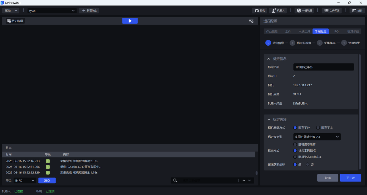
Enter the eye-hand calibration interface, click Add Eye-Hand Calibration, and enter the calibration information configuration interface.
Calibration Namecan be used to name the current calibration configurationCalibration IDis used by the Robot to switch calibration configurationsCamerais the IP address of the currently connected CameraCamera Brandis the brand of the currently connected CameraRobot Typemust be consistent with the Robot type in Robot ConfigurationFor
Camera Installation Method, selectEye-to-HandFor
Calibration Board Type, select the current Calibration Board type
The appropriate Calibration Board mainly depends on the Robot type and Camera height. Please select a suitable Calibration Board according to the actual application scenario and the table below.
| Robot Type | Camera Mounting Height | Select Calibration Board |
|---|---|---|
| Six-axis Robot | Under 0.5 m | A6 Multi-Concentric-Circle Calibration Board |
| Under 1.5 m | A5 Multi-Concentric-Circle Calibration Board | |
| 1.5 m -- 2.5 m | A4 Multi-Concentric-Circle Calibration Board | |
| Over 2.5 m | A3 Multi-Concentric-Circle Calibration Board | |
| Three-axis/Four-axis Robot | Under 0.5 m | A6 Multi-Concentric-Circle Calibration Board |
| Under 1.5 m | A5 Multi-Concentric-Circle Calibration Board | |
| 1.5 m -- 2.5 m | A4 Multi-Concentric-Circle Calibration Board | |
| Over 2.5 m | A3 Multi-Concentric-Circle Calibration Board |
For
Calibration Method, selectRandom Pose Sampling CalibrationIf the Robot has a corresponding calibration program, and the Robot needs to run that program to send the pose to PickWiz while sampling the Calibration Board, then for
Get Coordinates Online** selectYes; if the Robot does not have a corresponding calibration program, and the pose of the Robot end Tool must be entered manually while sampling the Calibration Board, then forGet Coordinates Online**selectNo.
1.3 Checks Before Calibration

- Ensure that the Robot base is securely installed
Before starting eye-hand calibration, carefully inspect the installation of the Robot base. If the Robot base is not firmly installed, the Robot may shake noticeably during movement, affecting Robot accuracy and thus the calibration result.
Check whether the Robot base installation meets the requirements as follows:
First, the surface where the Robot base is installed must be flat and kept clean;
Second, operate the Robot at 100% speed with large translational or rotational movements and observe whether there are signs of shaking. If shaking is present, readjust and secure the Robot base to ensure that no displacement or tilting occurs during Robot movement;
Third, check whether the Robot body and the base are tightly connected, and tighten the screws to prevent loosening.
- Ensure that the Camera and its bracket are securely installed
Before starting eye-hand calibration, carefully inspect the installation of the Camera and its bracket. If the Camera and its bracket are not firmly installed, Camera imaging quality will be affected, which in turn will affect the calibration result.
Check whether the Camera and its bracket installation meets the requirements as follows:
First, check whether the Camera bracket is a machined part, and avoid using aluminum profiles as the bracket material;
Second, shake the bracket and observe whether there is any obvious wobbling. If so, readjust and secure the bracket;
Third, shake the Camera and observe whether there is any obvious wobbling to ensure that the Camera is firmly installed.
- Ensure that the Calibration Board is stably placed within the Camera field of view
When the Camera installation method is Eye to hand, the Calibration Board must be mounted on the Tool and kept within the Camera field of view.
- Ensure that Robot accuracy meets the project requirements
If Robot accuracy does not meet the project requirements, please refer to Calibration Verification to correct Robot accuracy.
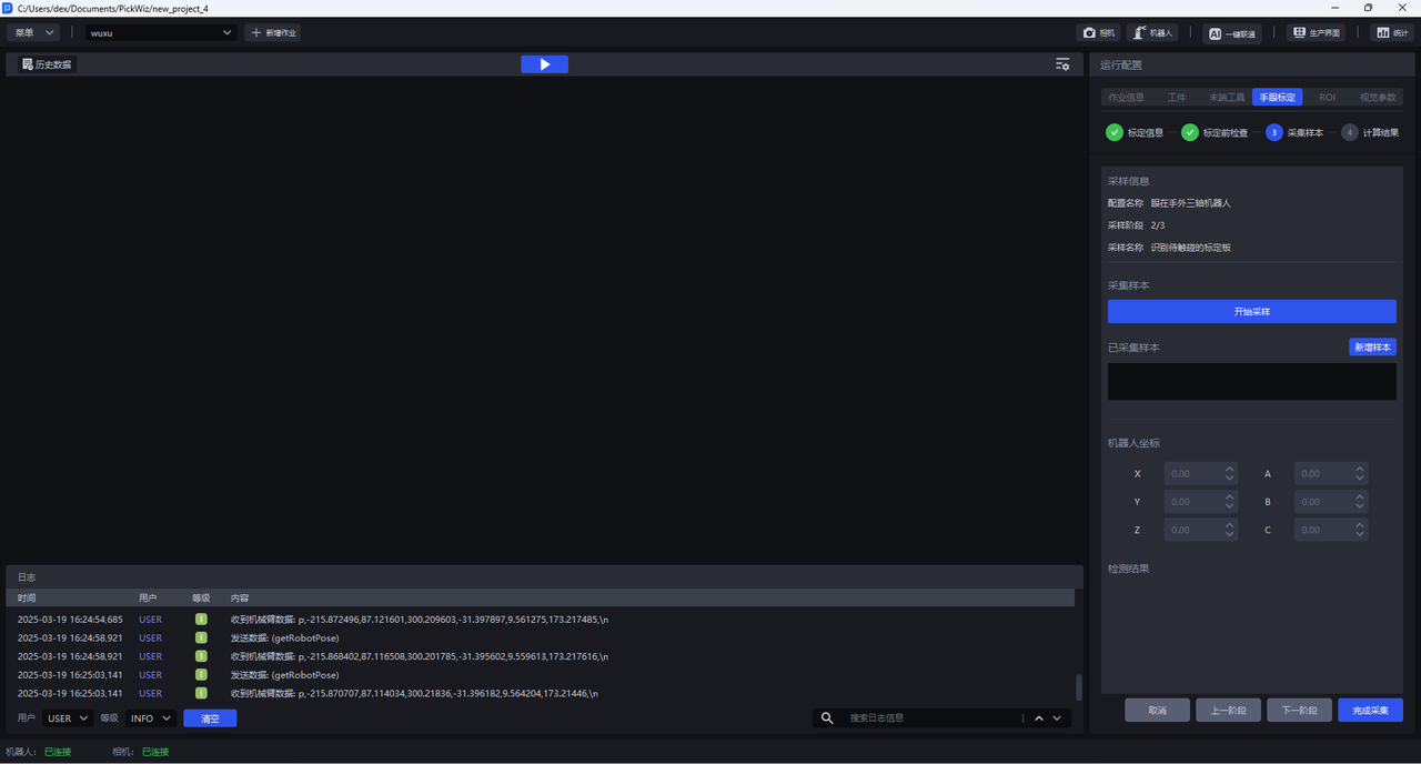
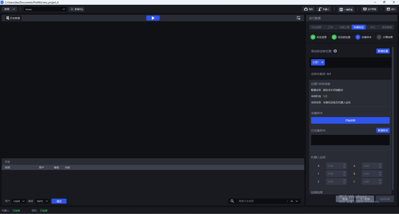
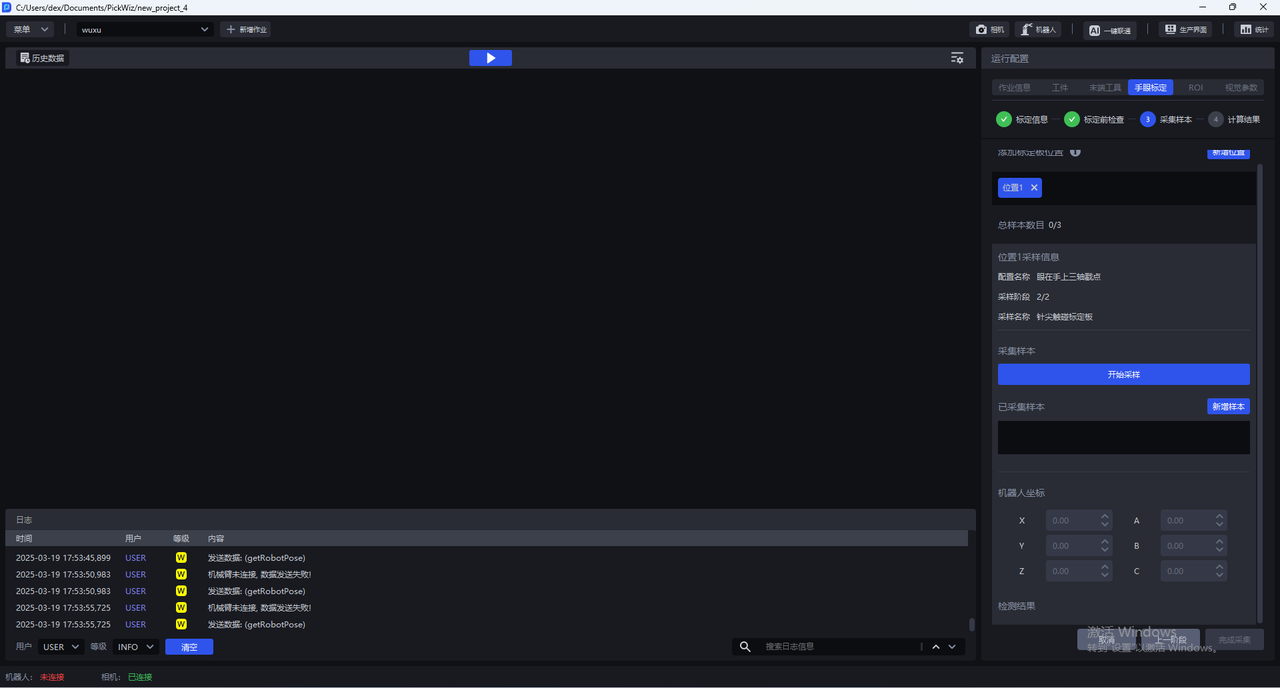
1.4 Collect Samples

1.4.1 Collect Multiple Sets of Calibration Board and Robot Coordinates
(1) Control the Robot carrying the Calibration Board to move so that the Calibration Board is at the center of the Camera field of view and parallel to the Camera imaging plane.
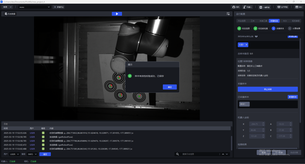
(2) Click Start Sampling. The Start Sampling button changes to Stop Sampling, and the Detection Results Panel below displays two types of detection results: Camera and Robot. If both Camera detection and Robot detection are green icons, the detection passes. If any red icon appears, the detection has failed and should be checked.

(3) Camera detection is divided into 4 aspects:
(4) Robot detection is divided into 3 aspects:
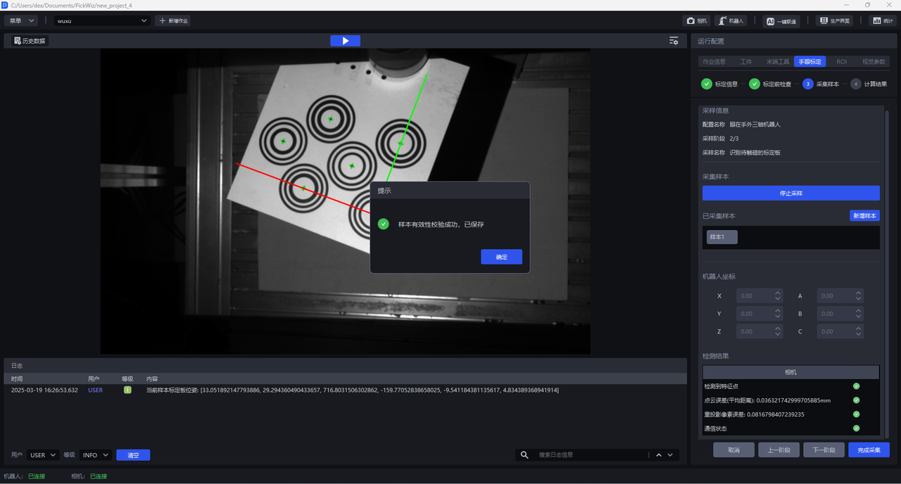
(5) If coordinate axes appear on the Calibration Board in the visualization window and the centers of all concentric circles are green, the current pose meets the requirements.

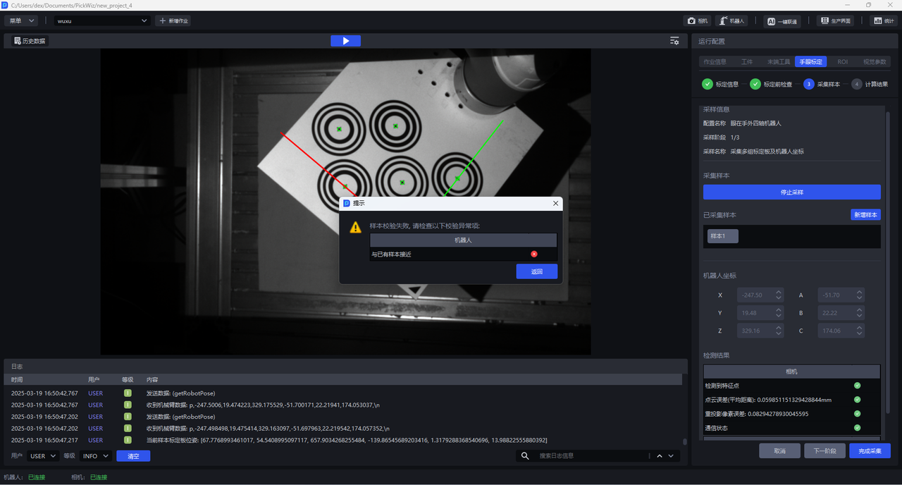
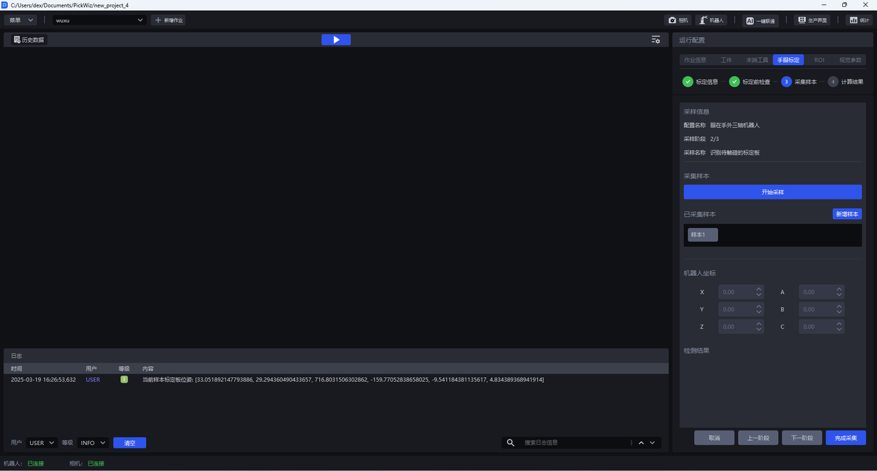
(6) Click Add Sample. If the sample is valid, a Sample Validity Check Passed popup appears. After you click OK, Sample 1 appears under Collected Samples. Click Sample 1 to view the saved sample, and click the close button after Sample 1 to delete the sample.

If the sample is close to an existing sample, the sample is invalid. A Sample Validation Failed popup appears with the message Close to Existing Samples. Click Back, then control the Robot carrying the Calibration Board to move and collect the sample again.
(7) Control the Robot carrying the Calibration Board to move so that the Calibration Board reaches the four corners of the Camera field of view, and the rotation angles on the X, Y, and Z axes are all greater than 10°. Repeat the above sample collection steps until at least 5 samples are saved.
(8) After saving at least 5 valid samples, click Finish Collection to enter the Calculation Results interface.
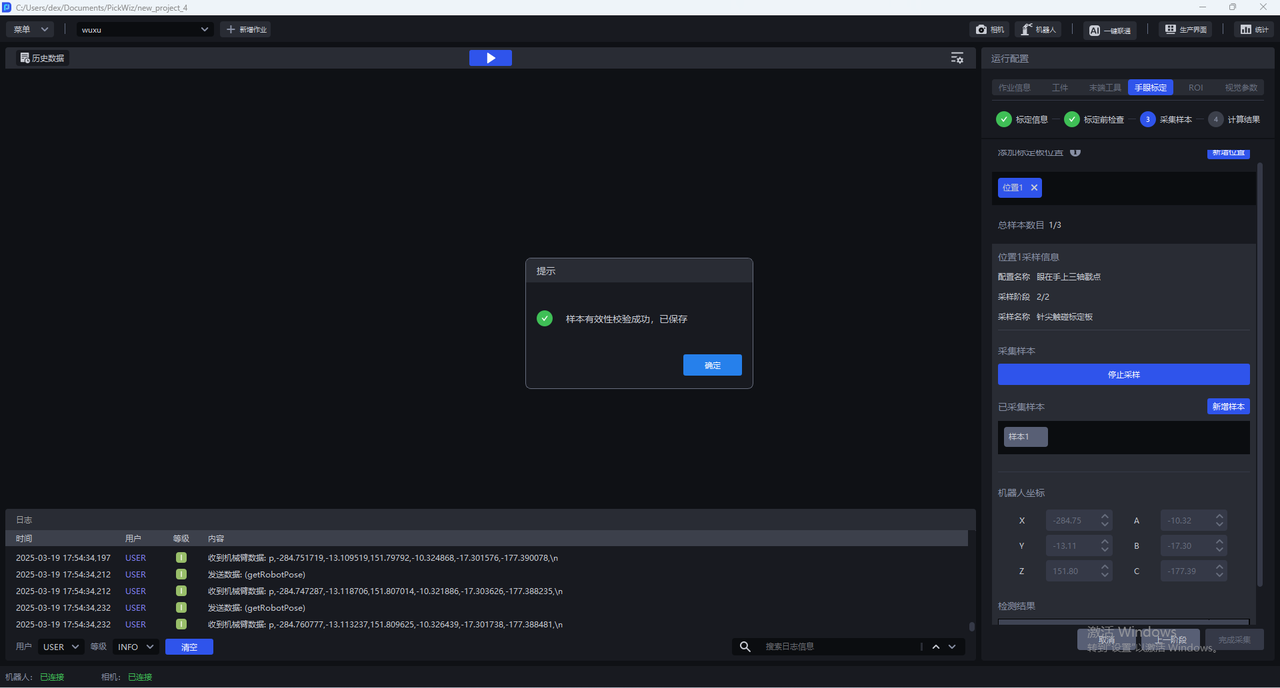
1.4.2 Identify the Calibration Board to Be Touched
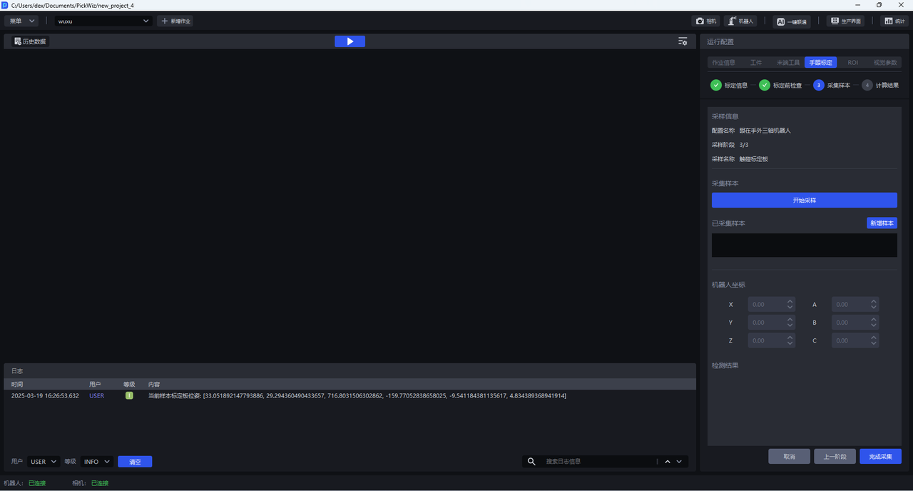
(1) Place the Calibration Board within the Camera field of view and ensure that the Robot with the pin tip installed can touch the Calibration Board.
(2) Click Start Sampling until coordinate axes and feature points appear in the visualization window and all dots are green, indicating that the current pose meets the requirements.
(3) Click Add Sample. If the sample is valid, Saved Successfully is displayed. If the sample is close to an existing sample, the sample is invalid and a save failure message is displayed.
(4) Click Next
1.4.3 Touch the Calibration Board
- (1) Click
Start Sampling, control the Robot to move, and have the pin tip touch the center of each corresponding concentric circle in the numerical order marked in the visualization window.
(2) Click Add Sample to collect the Robot coordinates at the moment of contact-point sampling.

(3) Repeat the above steps to collect at least 3~6 concentric-circle contact-point samples.
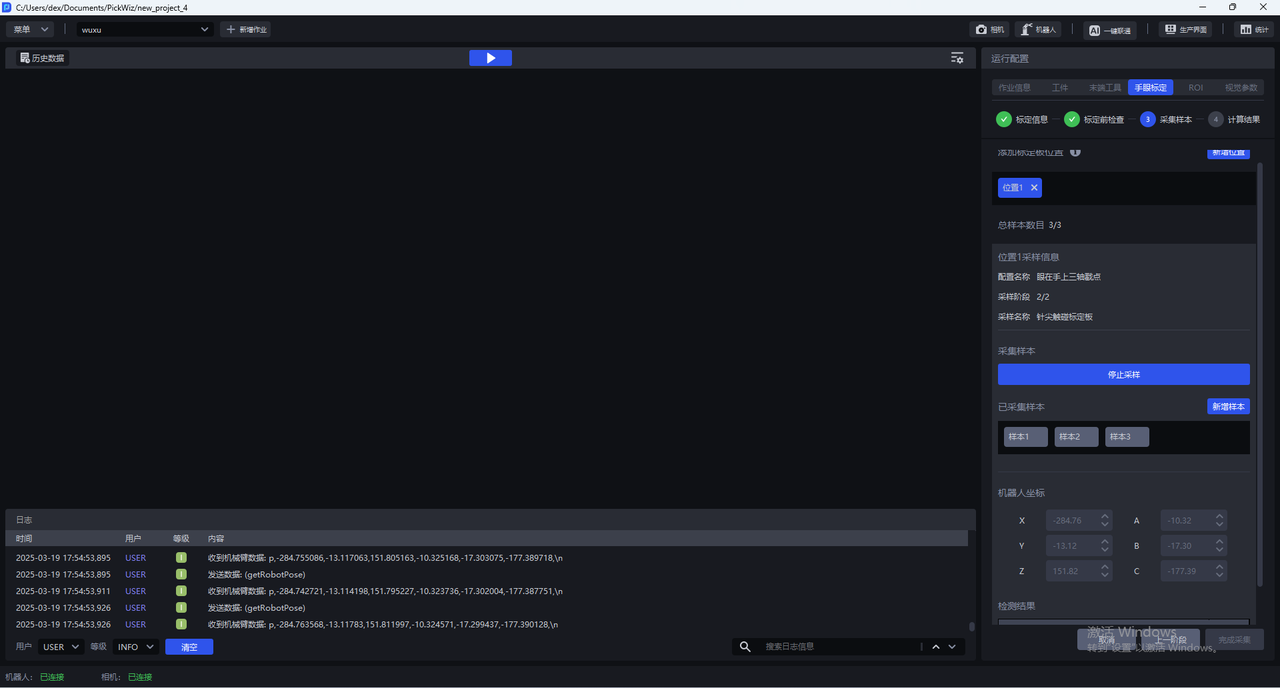
- Click
Next
1.4.4 Calculate Calibration Results
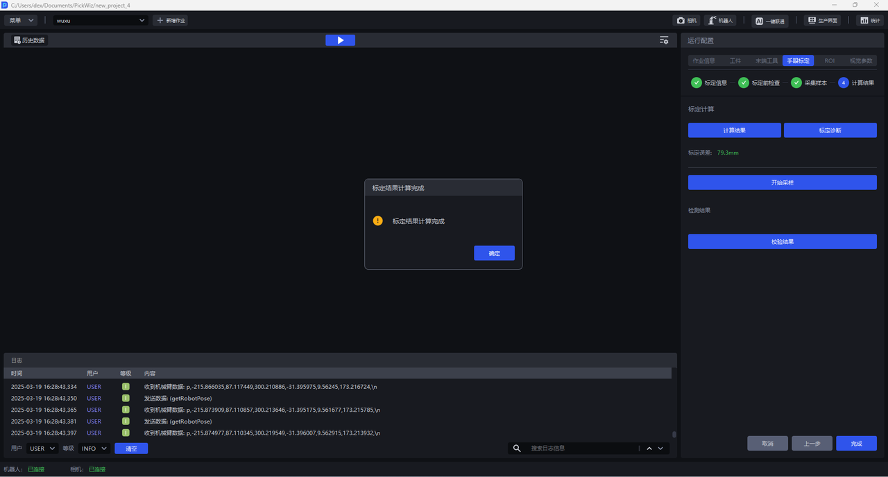
Click Calculate Results. PickWiz calculates the calibration result based on the collected samples. If the calibration error does not meet the requirements, perform Calibration Result Inspection and Analysis.
1.5 Calibration Result Inspection and Analysis
If the Calibration Error exceeds the normal range, the cause of the error must be identified. Click Calibration Diagnosis, then refer to Calibration Result Inspection and Analysis to analyze the calibration result, resolve the issue, and check again until the calibration accuracy meets the application requirements.
1.6 Select the Eye-Hand Calibration Configuration
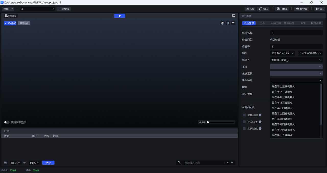
After the calibration workflow is completed, return to the Run Configuration interface, click Job Information, click the dropdown list for Eye-Hand Calibration, and select the corresponding eye-hand calibration configuration.
2. Pin Tool Contact-Point Calibration
2.1 Preparation Before Calibration
Before starting eye-hand calibration, complete the following preparations:
(1) Complete the 3D Vision Guidance Kit hardware setup
Please refer to 3D Vision Guidance Kit Hardware Setup to complete the installation and connection of the Robot, Camera, and IPC
(2) Create a Project and a task
Please refer to Project Operation Guide and Task Operation Guide to create a Project and a task.
(3) Complete Camera connection and parameter tuning, then configure it in the task information
Please refer to Camera Connection and Parameter Tuning Guide to connect the Camera, perform camera imaging quality adjustment, verify Camera accuracy, and configure it in the task information.
(4) Complete Robot communication configuration
Please refer to Robot Configuration and Communication Operation Guide to establish communication between the Robot and PickWiz
(5) Prepare the materials required for calibration
Please ensure that the Calibration Board is flat and clear, with no obvious scratches, dirt, bending, or deformation
Install the pin-tip device on the Robot end, create the corresponding Tool coordinate system, and verify that the Tool coordinate system is accurate
After TCP calibration is completed, try moving the Robot under this Tool coordinate system. For four-axis robots, the positive Z-axis usually points downward along the Robot end
You can also inspect the calibrated Tool coordinate values. If the pin-tip device is installed as shown below and extends along the center of the Flange, the TCP x and y should be 0
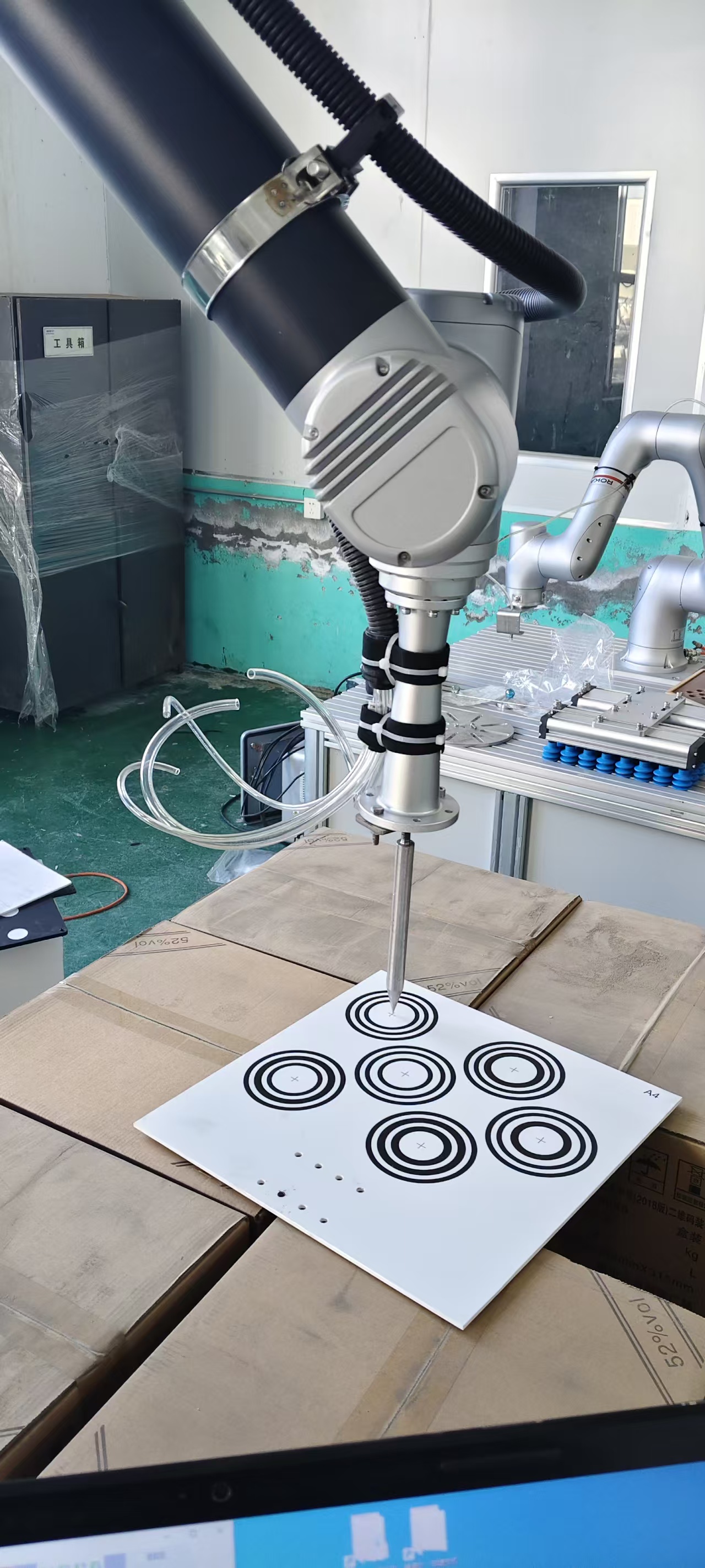
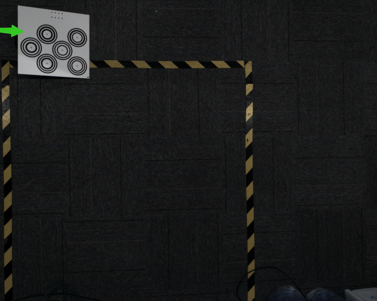
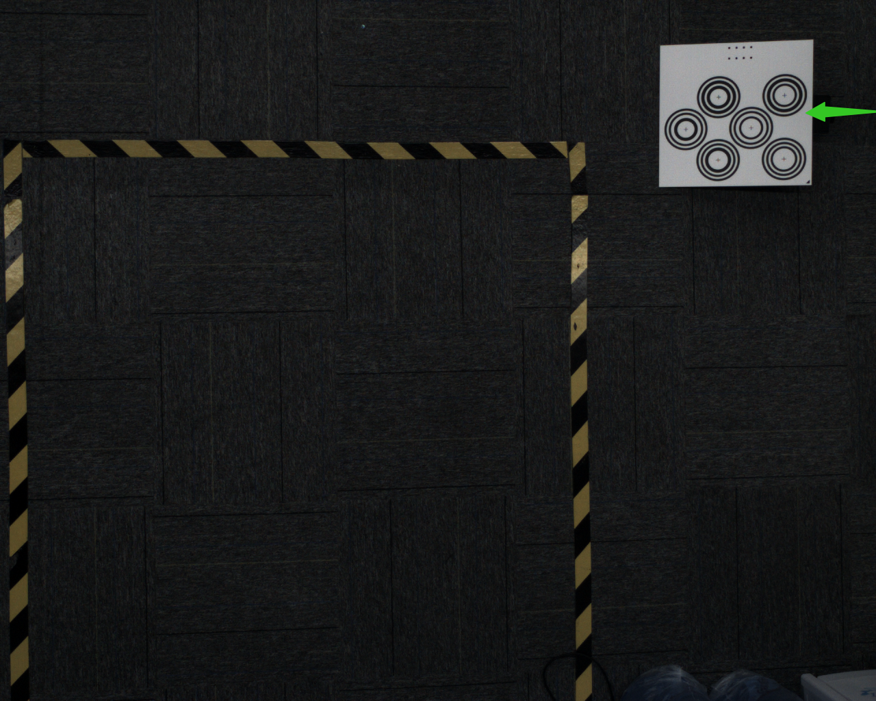
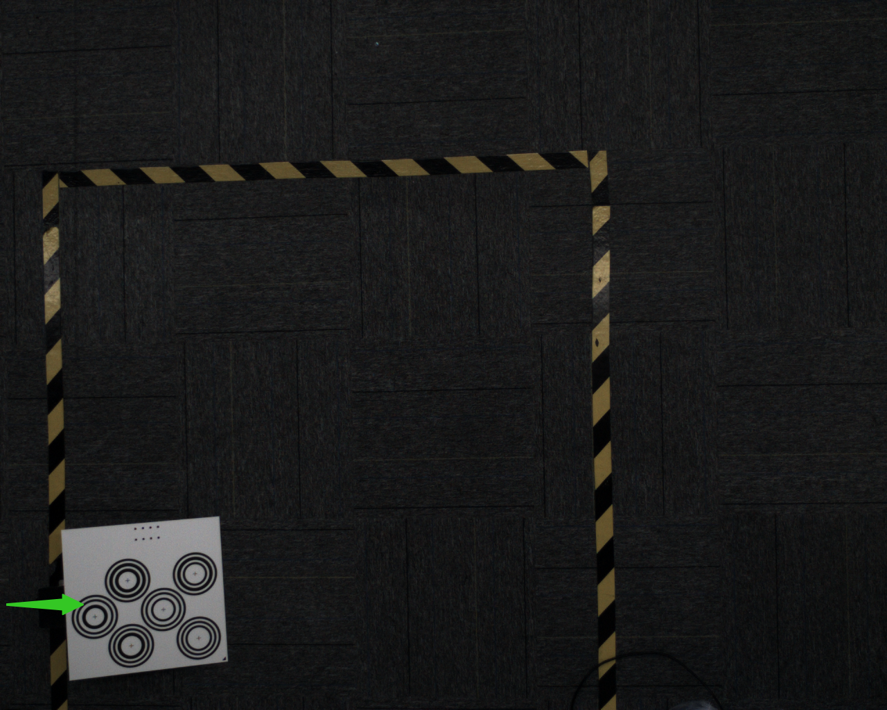
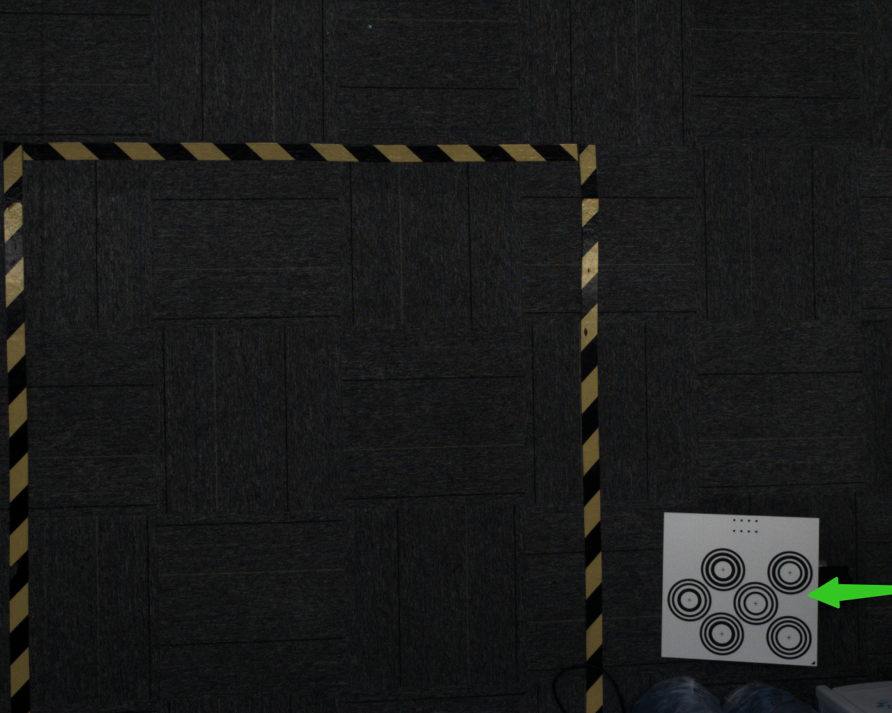
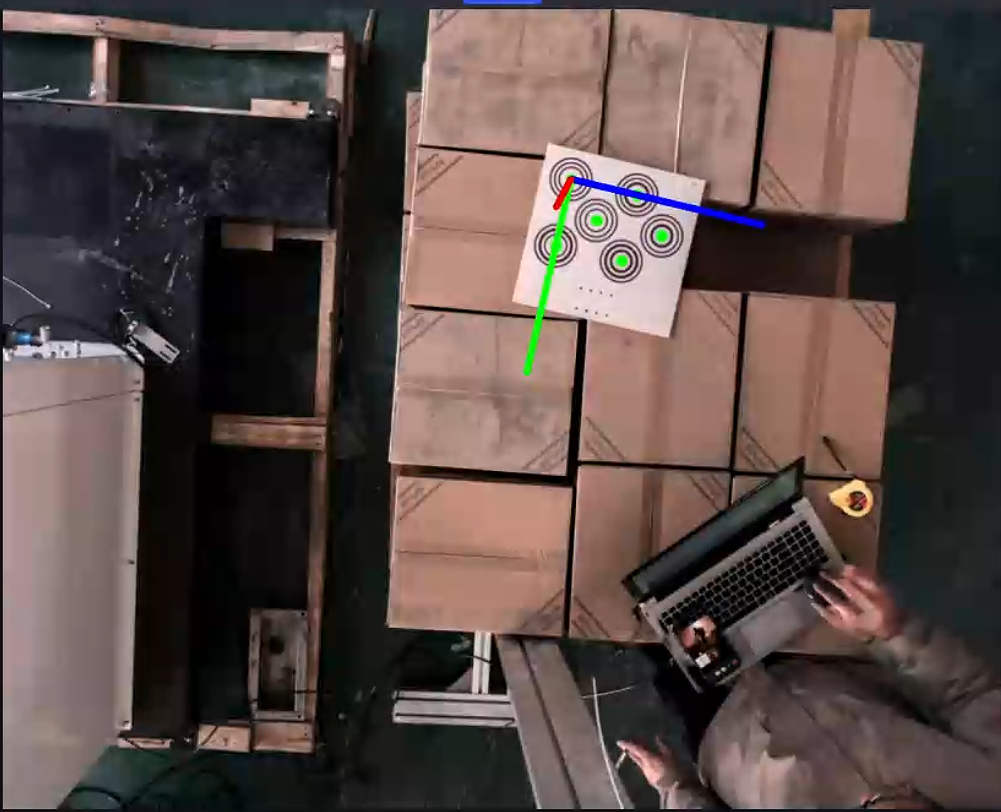
For the pin tool contact-point calibration method, please ensure that the Calibration Board is placed horizontally on the work platform and is within the Camera field of view, as shown below.
2.2 Calibration Information Configuration
Enter the eye-hand calibration interface, click Add Eye-Hand Calibration, and enter the calibration information configuration interface.
Calibration Namecan be used to name the current calibration configurationCalibration IDis used by the Robot to switch calibration configurationsCamerais the IP address of the currently connected CameraCamera Brandis the brand of the currently connected CameraRobot Typemust be consistent with the Robot type in Robot Configuration- If a six-axis Robot is displayed here, go to Robot Configuration and change it to four-axis. Save the change, then return to the eye-hand calibration configuration and create a new calibration for the change to take effect
For
Camera Installation Method, selectEye-to-HandFor
Calibration Board Type, select the current Calibration Board type
The appropriate Calibration Board mainly depends on the Robot type and Camera height. Please select a suitable Calibration Board according to the actual application scenario and the table below.
| Robot Type | Camera Mounting Height | Select Calibration Board |
|---|---|---|
| Six-axis Robot | Under 0.5 m | A6 Multi-Concentric-Circle Calibration Board |
| Under 1.5 m | A5 Multi-Concentric-Circle Calibration Board | |
| 1.5 m -- 2.5 m | A4 Multi-Concentric-Circle Calibration Board | |
| Over 2.5 m | A3 Multi-Concentric-Circle Calibration Board | |
| Three-axis/Four-axis Robot | Under 0.5 m | A6 Multi-Concentric-Circle Calibration Board |
| Under 1.5 m | A5 Multi-Concentric-Circle Calibration Board | |
| 1.5 m -- 2.5 m | A4 Multi-Concentric-Circle Calibration Board | |
| Over 2.5 m | A3 Multi-Concentric-Circle Calibration Board |
For
Calibration Method, selectPin-Tip Touch CalibrationIf the Robot has a corresponding calibration program, and the Robot needs to run that program to send the pose to PickWiz while sampling the Calibration Board, then for
Get Coordinates Online** selectYes; if the Robot does not have a corresponding calibration program, and the pose of the Robot end Tool must be entered manually while sampling the Calibration Board, then forGet Coordinates Online**selectNo.
2.3 Checks Before Calibration
Ensure that the Robot base is securely installed
Before starting eye-hand calibration, carefully inspect the installation of the Robot base. If the Robot base is not firmly installed, the Robot may shake noticeably during movement, affecting Robot accuracy and thus the calibration result.
Check whether the Robot base installation meets the requirements as follows:
First, the surface where the Robot base is installed must be flat and kept clean;
Second, operate the Robot at 100% speed with large translational or rotational movements and observe whether there are signs of shaking. If shaking is present, readjust and secure the Robot base to ensure that no displacement or tilting occurs during Robot movement;
Third, check whether the Robot body and the base are tightly connected, and tighten the screws to prevent loosening.
Ensure that the Camera and its bracket are securely installed
Before starting eye-hand calibration, carefully inspect the installation of the Camera and its bracket. If the Camera and its bracket are not firmly installed, Camera imaging quality will be affected, which in turn will affect the calibration result.
Check whether the Camera and its bracket installation meets the requirements as follows:
First, check whether the Camera bracket is a machined part, and avoid using aluminum profiles as the bracket material;
Second, shake the bracket and observe whether there is any obvious wobbling. If so, readjust and secure the bracket;
Third, shake the Camera and observe whether there is any obvious wobbling to ensure that the Camera is firmly installed.
Ensure that the Calibration Board is stably placed within the Camera field of view
- When the Camera installation method is Eye to hand, place the Calibration Board at a possible incoming-material position and ensure that it is within the Camera field of view.
Ensure that Robot accuracy meets the project requirements
- If Robot accuracy does not meet the project requirements, please refer to Calibration Verification to correct Robot accuracy.
Ensure that the Tool coordinate system of the contact-point device meets the accuracy requirements
- TCP accuracy can be verified by rotating pin tip to pin tip under the Tool coordinate system
2.4 Collect Samples
2.4.1 Collect Calibration Board and Robot Coordinates
(1) Adjust the position of the Calibration Board, place it within the target object placement area, and click Start Sampling.
(2) Click Add Sample. If the sample is valid, Saved Successfully is displayed. If the sample is close to an existing sample, the sample is invalid and a save failure message is displayed.
(3) Check the detection result. If all inspection items show green icons, coordinate axes and feature points appear in the visualization window, and all circle centers are green, the current pose meets the requirements.
Detection is divided into 4 aspects:
2.4.2 Touch the Calibration Board with the Pin Tip
(1) Click Start Sampling, control the Robot to move, and have the pin tip touch the center of each corresponding concentric circle in the numerical order marked in the visualization window.
(2) Click Add Sample to collect the Robot coordinates at the moment of contact-point sampling.
(3) Repeat the above steps to collect at least 3~6 concentric-circle contact-point samples.

- Click
Next
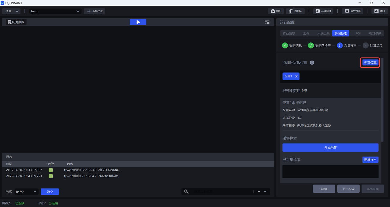
2.4.3 [Optional] Add a New Calibration Position
During the calibration sampling stage, the system uses a single-pose calibration mode by default. However, in specific application scenarios, it can be extended to a multi-position calibration strategy, improving calibration robustness and system adaptability under complex working conditions:
To address accuracy deviation caused by depth-of-field changes in wide-angle vision systems, layered sampling along the Z-axis can effectively balance the error distribution across different focal planes;
For space-constrained work environments, when a single Calibration Board placement cannot complete the collection of more than 3 feature points, a multi-position Calibration Board placement and batch-by-batch sampling method can be used to cumulatively satisfy the minimum sample size requirement.
Click Add Position to add a new calibration position, then repeat 2.4.1 Collect Calibration Board and Robot Coordinates and 2.4.2 Touch the Calibration Board with the Pin Tip to collect calibration samples and perform Calibration Board contact-point sampling.
2.4.4 Calculate Calibration Results
Click Calculate Results. PickWiz calculates the calibration result based on the collected samples. If the calibration error does not meet the requirements, perform Calibration Result Inspection and Analysis.

2.5 Calibration Result Inspection and Analysis
If the Calibration Error exceeds the normal range, the cause of the error must be identified. Click Calibration Diagnosis, then refer to Calibration Result Inspection and Analysis to analyze the calibration result, resolve the issue, and check again until the calibration accuracy meets the application requirements.
2.6 Select the Eye-Hand Calibration Configuration
After the Calibration Workflow is completed, return to the Run Configuration interface, click Job Information, click the dropdown list for Eye-Hand Calibration, and select the corresponding eye-hand calibration configuration.
