Guide to Adjusting Vision Parameters for Ordered Loading and Unloading of Planar Target Objects (Parallelized)
Getting Started
Background Introduction
The new "Ordered Loading and Unloading of Planar Target Objects (Parallelized)" scenario is a vision acceleration solution for ordered planar scenes. Its main feature is that it improves visual computation Takt Time, reduces intermediate computation steps such as instance generation/filtering and pose generation, and directly generates Pick Points.
Unlike the way visual acceleration mode is enabled in other scenarios, the ordered planar scenario is enabled by creating a new task.
Task Scenario Selection
In the current ordered planar scenario, there are two available task scenarios. Their comparison is shown in the table below.
| Workflow | Ordered Loading and Unloading of Planar Target Objects | Ordered Loading and Unloading of Planar Target Objects (Parallelized) | Remarks |
|---|---|---|---|
| Accuracy | High, depends on Point Cloud density and scene Point Cloud consistency | Relatively high, depends on image features, Point Cloud density, and scene Point Cloud consistency | / |
| Speed | Relatively fast (single instance) | Fast (multiple instances) | Only the parallelized mode can output all valid results in the scene |
| Parameter tuning | Medium, requires matching parameter tuning experience | Simple, relatively simple and fixed (similar to general target objects) | Some advanced parameters will be hidden in the parallelized mode in the future |
| Applicability | Strong, suitable for all planar target objects | Relatively weak; the current version supports cases where incoming material orientations are inconsistent | The parallelized mode has been updated with multi-template mode and supports multiple incoming directions |
| Template creation difficulty | Average, software-supported | Relatively complex, the current version requires scripts | Template creation for the parallelized mode will be integrated into PickWiz in the future |
| Template characteristics | For reference | Select a complete scene instance Point Cloud relatively centered in the Camera field of view | / |
Build a Project
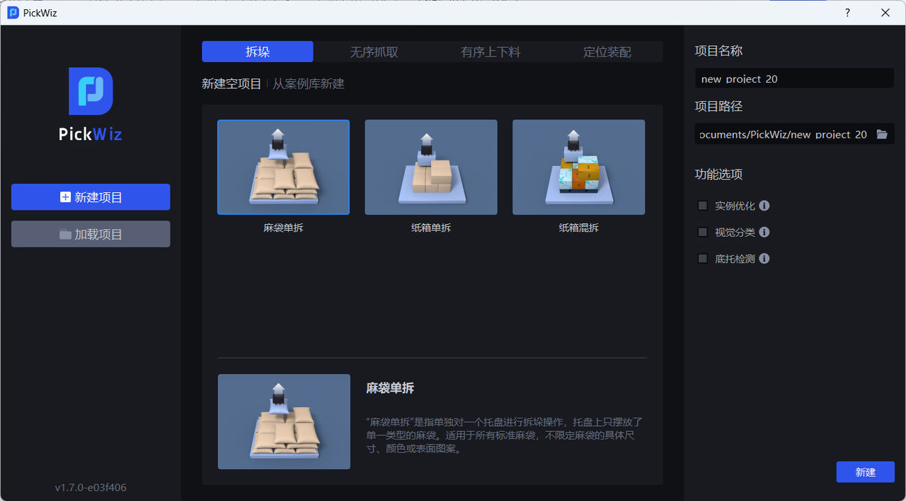
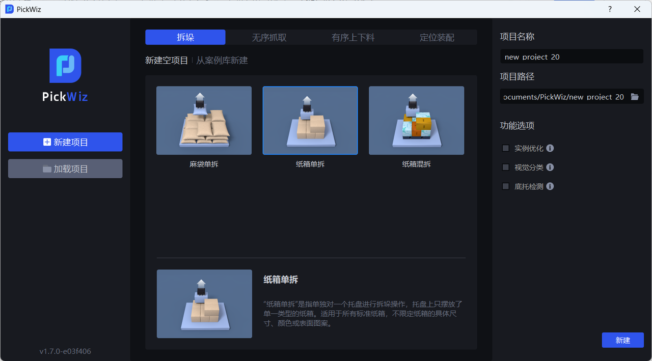
(1)Create a new ordered loading and unloading project for planar target objects (parallelized) (the project name and project path can be customized, but the project name cannot contain Chinese characters)
Target Object type: planar target objects (not circular, cylindrical, or quadrilateral, and with relatively small differences between the front and back sides)

(2)Camera and Robot configuration
(3)Add Target Object
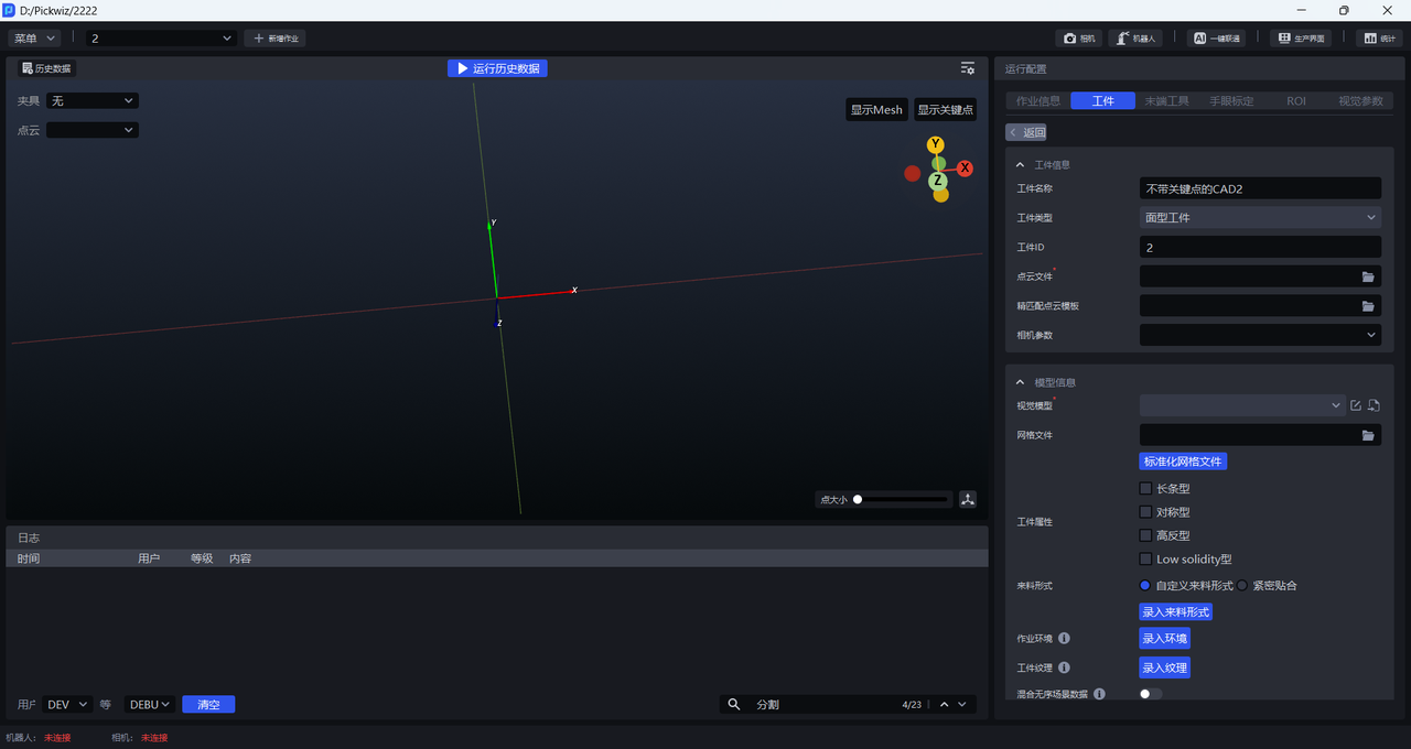
- Target Object Information
The Target Object name can be customized. The Target Object type defaults to standard target object and cannot be changed. The Target Object ID can be customized and is used for automatic Target Object switching during Robot picking.
Point Cloud file: the Target Object Point Cloud template. In the ordered loading and unloading scenario for planar target objects (parallelized), the Point Cloud file is special. For the creation method, refer to 2.2.1 Template File Path.
Fine matching Point Cloud template: used for fine matching.
Camera parameters: not required.
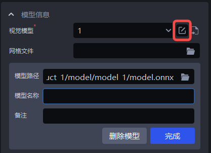
- Model Information
Vision model: the 2D Recognition solution used for planar target object applications is CAD-Based Synthetic Data Training (One-click Connection). The vision model for different planar target object applications must be obtained through one-click connection training.
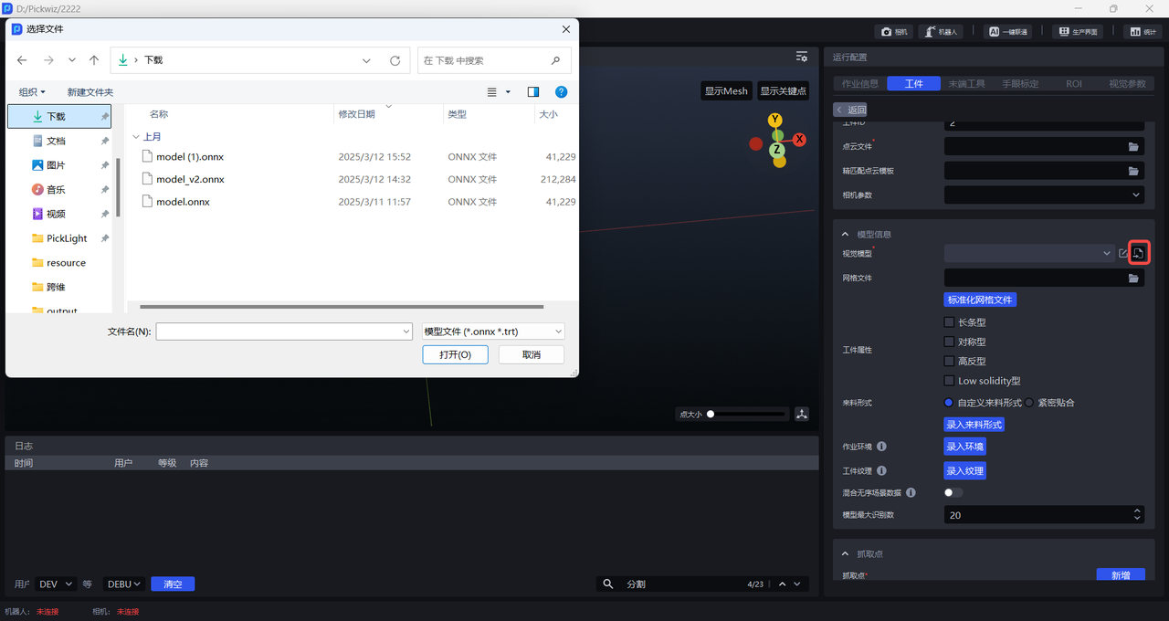
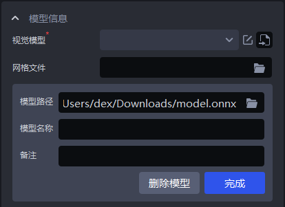
Mesh file: normally upload the Target Object CAD. To eliminate some noise, a standardized mesh file is required. The mesh file can also be standardized in Point Cloud Template Creation.
Target Object attributes: elongated, symmetrical, highly reflective, and low-solidity.
Incoming material type: custom incoming material type — enter the incoming material type; tightly fitted — the range of the number of target objects in each row and column.
task environment: enter the environment file. In one-click connection, the environment used for data generation will be automatically replaced with the entered environment to improve recognition performance.
Target Object texture: enter the Target Object texture. During model training in one-click connection, the entered Target Object texture will be used for data augmentation to improve recognition performance.
Mixed random-scene data: when enabled, one-click connection generates synthetic data for both random and ordered scenes during model training to improve recognition performance.
Maximum number of model recognitions: the default is 20; modify it according to scene requirements.
- Pick Point: configure the Pick Point according to the Target Object.
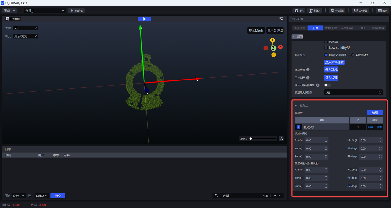
Absolute coordinate system: uses the initial point as the origin. The initial point is built into the Target Object Point Cloud and CAD.
Pick Point coordinate system (offset): uses the current Pick Point as the origin.
(4)Add Tool, eye-hand calibration, and ROI
(5)Optional functional options: instance optimization, collision detection, collision detection (new), visual classification, front/back recognition (via Point Cloud templates)
Instance optimization: optimizes instances generated by the model and processes the instance Masks.
Collision detection (new): this function is used to detect collisions between the Tool and the container, and to filter out Picking Poses that may collide. Collision Detection User Guide
Visual classification: used to identify features such as different textures and different orientations of the same target object. Visual Classification User Guide
Front/back recognition (via Point Cloud templates): you can import the front-side and back-side Point Cloud templates of the target object to match the front or back side of the picked target object, and you can configure Pick Points separately for the front and back sides. Front/Back Recognition (via Point Cloud Templates) User Guide
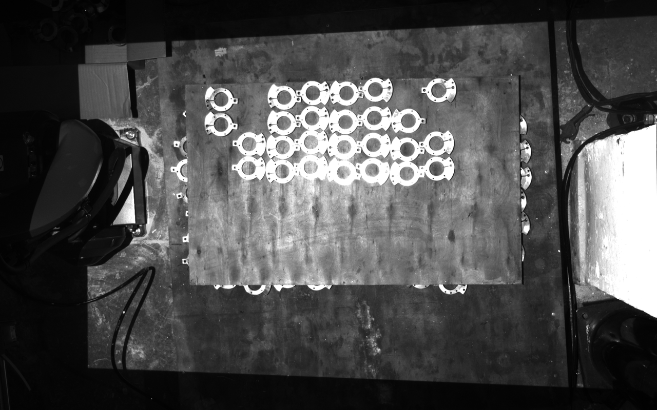
(6)Test data (historical data is provided for subsequent practice. You can use the 2D images and 3D Point Clouds in the foreground\input folder of the historical data to configure the ROI instead of capturing images with the Camera)
Ordered loading and unloading data for planar target objects:
Point Cloud file:
Mesh file:
Vision model:
Tool:
Historical data:
Vision Parameters
- 2D Recognition: recognize and segment instances from the actual scene
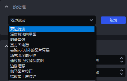
Preprocessing: process the 2D image before instance segmentation (commonly used: fill holes in the depth map & edge enhancement & extract the top-layer texture & remove image background outside ROI 3D)
Instance Segmentation: segment instances (scaling ratio & lower Confidence threshold & auto enhancement). To accelerate processing, you can clear the checkbox for Return Mask.
Point Cloud Generation: the method for generating instance Point Clouds — generate instance Point Clouds using segmented instance Masks or bounding boxes / generate instance Point Clouds using filtered instance Masks or bounding boxes
Instance Filtering: filter the segmented instances
Instance Sorting: sort instances
- 3D Computation: calculate the instance pose in the Camera coordinate system and generate Pick Points
Preprocessing: preprocess the 3D Point Cloud before calculating Pick Points
Pose estimation: calculate the instance pose in the Camera coordinate system (coarse matching and fine matching) and generate Pick Points
- Pick Point Processing: filter, adjust, and sort Pick Points
Pick Point filtering: filter Pick Points
Pick Point adjustment: adjust Pick Points
Pick Point sorting: sort Pick Points
1. 2D Recognition
1.1 Preprocessing
Preprocessing for 2D Recognition is performed on the 2D image before instance segmentation.
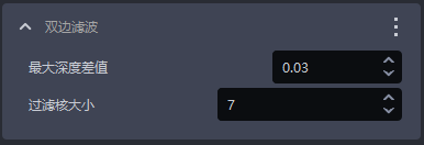
1.1.1 Bilateral Filtering
- Function
Image smoothing based on bilateral filtering
- Parameter Description
| Parameter | Description | Default Value | Value Range |
|---|---|---|---|
| Maximum depth difference | The maximum depth difference for bilateral filtering | 0.03 | [0.01, 1] |
| Filter kernel size | The convolution kernel size for bilateral filtering | 7 | [1, 3000] |
1.1.2 Convert Depth to Normal Map
- Function
Compute pixel normals from the depth map and convert the image into a normal map
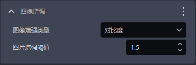
1.1.3 Image Enhancement
- Function
Common image enhancement operations such as color saturation, contrast, brightness, and sharpness
- Parameter Description
| Parameter | Description | Default Value | Value Range |
|---|---|---|---|
| Image enhancement type | Enhance a certain element of the image | Contrast | Color saturation, contrast, brightness, and sharpness |
| Image enhancement threshold | How much to enhance a certain element of the image | 1.5 | [0.1, 100] |
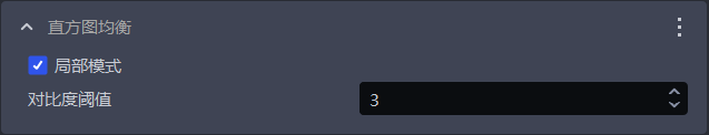
1.1.4 Histogram Equalization
- Function
Improve image contrast
- Parameter Description
| Parameter | Description | Default Value | Value Range |
|---|---|---|---|
| Local mode | Local or global histogram equalization. When selected, local histogram equalization is used; when cleared, global histogram equalization is used. | Selected | / |
| Contrast threshold | Contrast threshold | 3 | [1,1000] |
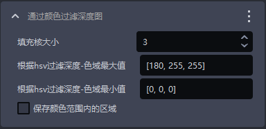
1.1.5 Filter Depth Map by Color
- Function
Filter the depth map according to color values
- Parameter Description
| Parameter | Description | Default Value | Value Range |
|---|---|---|---|
| Fill kernel size | The size of color filling | 3 | [1,99] |
| Max color range value for filtering depth by HSV | Maximum color value | [180,255,255] | [[0,0,0],[255,255,255]] |
| Min color range value for filtering depth by HSV | Minimum color value | [0,0,0] | [[0,0,0],[255,255,255]] |
| Keep areas within the color range | When selected, keep areas within the color range; when cleared, keep areas outside the color range | / | / |
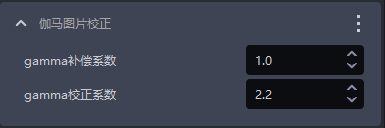
1.1.6 Gamma Image Correction
- Function
Gamma correction changes image brightness
- Parameter Description
| Parameter | Description | Default Value | Value Range |
|---|---|---|---|
| Gamma compensation factor | If this value is less than 1, the image becomes darker; if it is greater than 1, the image becomes brighter | 1 | [0.1,100] |
| Gamma correction factor | If this value is less than 1, the image becomes darker and is suitable for overly bright images; if it is greater than 1, the image becomes brighter and is suitable for overly dark images | 2.2 | [0.1,100] |
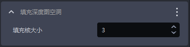
1.1.7 Fill Holes in the Depth Map
- Function
Fill the hole regions in the depth map and smooth the filled depth map
- Use Case
Due to issues such as structural occlusion of the target object itself and uneven lighting, some regions of the target object may be missing in the depth map
- Parameter Description
| Parameter | Description | Default Value | Value Range |
|---|---|---|---|
| Fill kernel size | The size of hole filling | 3 | [1,99] |
The fill kernel size can only be an odd number
- Tuning
Adjust according to the detection results. If the filling is excessive, reduce the parameter; if the filling is insufficient, increase the parameter.
- Example
1.1.8 Edge Enhancement
- Function
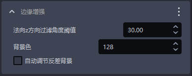
Set the texture edge regions in the image to the background color or to a color that contrasts strongly with the background color, thereby highlighting the edge information of the target object
- Use Case
Used when target objects occlude or overlap each other, resulting in unclear edges
- Parameter Description
| Parameter | Description | Default Value | Parameter Range | Tuning Suggestion |
|---|---|---|---|---|
| Normal Z-direction filtering threshold | The angle filtering threshold between the normal vector corresponding to each point in the depth map and the positive Z-axis direction of the Camera coordinate system. If the angle between the point normal and the positive Z-axis direction of the Camera coordinate system is greater than this threshold, the color at the corresponding position of that point in the 2D image will be set to the Background color or to a color that strongly contrasts with the Background color. | 30 | [0,180] | For flat target object surfaces, this threshold can be smaller; for curved target objects, increase it appropriately based on the degree of surface inclination |
| Background color | The RGB color threshold of the Background color | 128 | [0,255] | |
| Automatically adjust contrast background | When selected, the color of points in the 2D image whose angle is greater than the filtering threshold is set to a color that strongly contrasts with the Background color. When cleared, the color of points in the 2D image whose angle is greater than the filtering threshold is set to the color corresponding to the Background color. | Cleared | / |
- Example
1.1.9 Extract the Top-Layer Texture
- Function
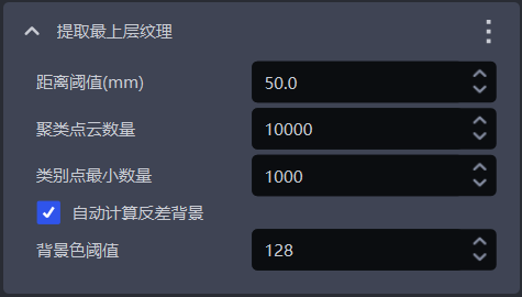
Extract the texture of the topmost or bottommost target object layer, and set other regions to the Background color or to a color that strongly contrasts with the Background color.
- Use Case
Factors such as poor lighting conditions, similar color textures, tight stacking, interleaved stacking, or occlusion may make it difficult for the model to distinguish the texture differences between upper and lower target objects, which can easily cause false detections.
- Parameter Description
| Parameter | Description | Default Value | Parameter Range | Unit | Tuning Suggestion |
|---|---|---|---|---|---|
| Distance threshold (mm) | If the distance between a point and the topmost plane (or bottommost plane) is lower than this threshold, the point is considered to be on the topmost plane (or bottommost plane) and should be retained; otherwise, it is considered a point on the lower layer (or upper layer), and its color is set to the Background color or to a color that strongly contrasts with the Background color | 50 | [0.1, 1000] | mm | Generally adjusted to half of the target object height |
| Number of clustered Point Clouds | The expected number of points participating in clustering, that is, the number of sampled Point Cloud points within the ROI 3D region | 10000 | [1,10000000] | / | The greater the number of clustered Point Clouds, the lower the model inference speed but the higher the accuracy; the smaller the number of clustered Point Clouds, the higher the model inference speed but the lower the accuracy |
| Minimum number of category points | The minimum number of points used to filter categories | 1000 | [1, 10000000] | / | / |
| Automatically calculate contrast background | When selected, regions outside the topmost (or bottommost) layer in the 2D image are set to a color that strongly contrasts with the Background color threshold. When cleared, regions outside the topmost (or bottommost) layer in the 2D image are set to the color corresponding to the Background color threshold. | Selected | / | / | / |
| Background color threshold | The RGB color threshold of the Background color | 128 | [0,255] | / | / |
1.1.10 Remove Image Background Outside ROI 3D
- Function
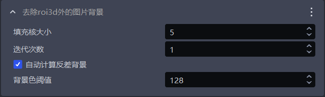
Remove the background in the 2D image outside the ROI 3D region
- Use Case
Used when heavy background noise in the image affects the detection results
- Parameter Description
| Parameter Name | Description | Default Value | Value Range |
|---|---|---|---|
| Fill kernel size | The size of hole filling | 5 | [1,99] |
| Number of iterations | The number of image dilation iterations | 1 | [1,99] |
| Automatically calculate contrast background | When selected, regions outside the ROI in the 2D image are set to a color that strongly contrasts with the Background color threshold. When cleared, regions outside the ROI in the 2D image are set to the color corresponding to the Background color threshold. | Selected | / |
| Background color threshold | The RGB color threshold of the Background color | 128 | [0,255] |
The fill kernel size can only be an odd number
- Tuning
If you need to remove more background noise from the image, reduce the fill kernel size
- Example
1.2 Instance Segmentation
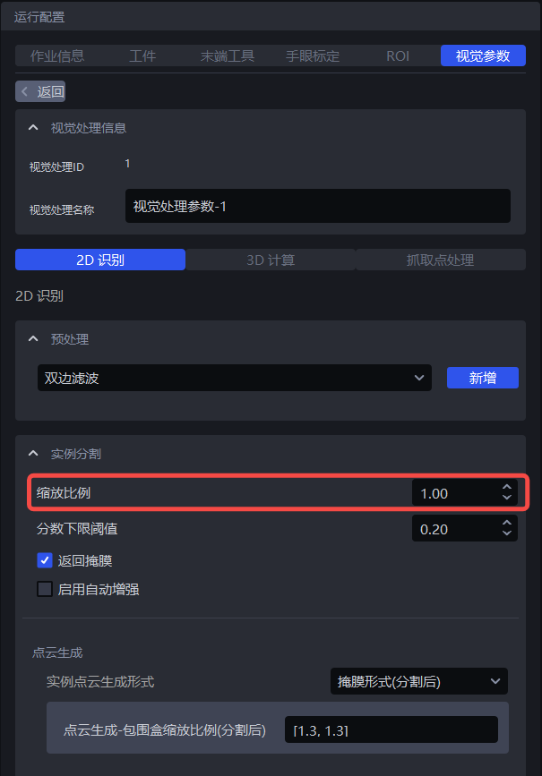
1.2.1 Scaling Ratio
- Function
Improve the accuracy and recall of 2D Recognition by uniformly scaling the original image before inference.
- Use Case
Adjust this function when the detection effect is poor (for example, no instance is detected, missed recognition occurs, one bounding box covers multiple instances, or the bounding box does not fully cover an instance).
- Parameter Description
Default value: 1.0
Value range: [0.01, 3.00]
Step size: 0.01
Tuning
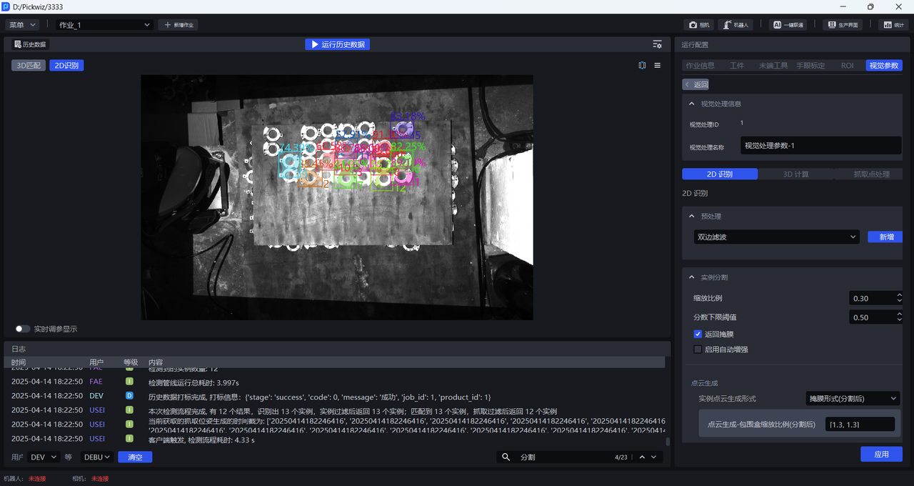
- Run with the default value and view the detection results in the visualization window. If no instance is detected, recognition is missed, one bounding box covers multiple instances, or the bounding box does not fully cover an instance, adjust this function.
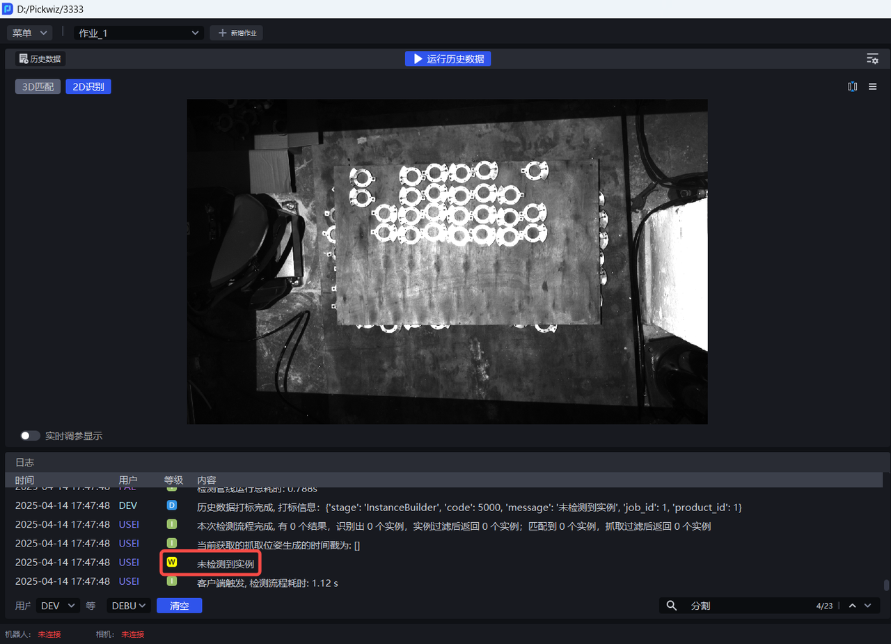

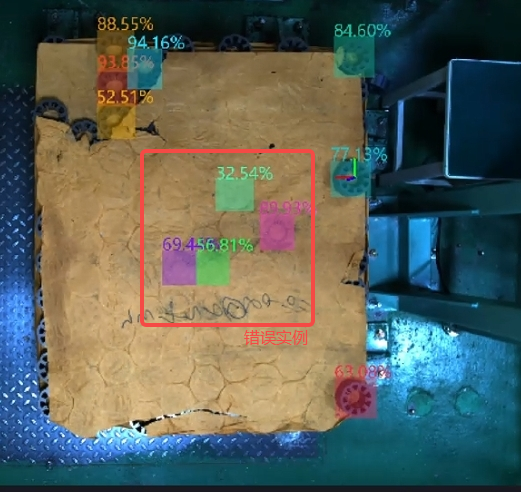
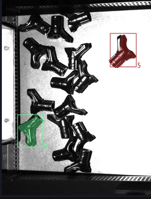
In 2D Recognition, the percentage shown on an instance is the Confidence score, and the number is the instance ID (the recognition order of the instance).
In 2D Recognition, the colored shadow on an instance is the Mask, and the rectangle surrounding the instance is the bounding box.
- Try different scaling ratios, observe changes in the detection results, and gradually determine the range of scaling ratios. If the detection effect improves significantly at a certain scaling ratio, use that scaling ratio as the lower bound; if the detection effect decreases significantly at a certain scaling ratio, use that scaling ratio as the upper bound.
If no good detection result can be obtained after trying all scaling ratios, adjust the ROI region
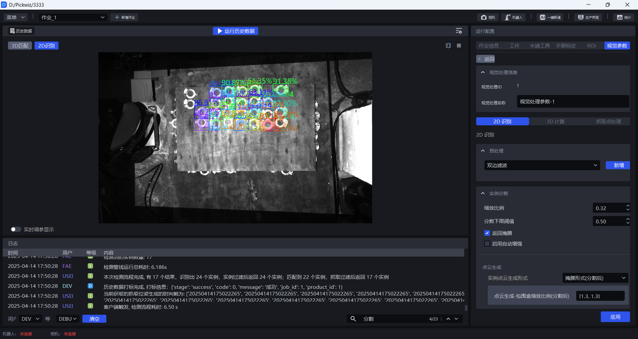
As shown below, when the scaling ratio is 0.33, the detection effect improves significantly, so 0.33 can be set as the lower bound of the scaling ratio range


When the scaling ratio is 3, the detection effect remains good, so 3 can be set as the upper bound of the scaling ratio range
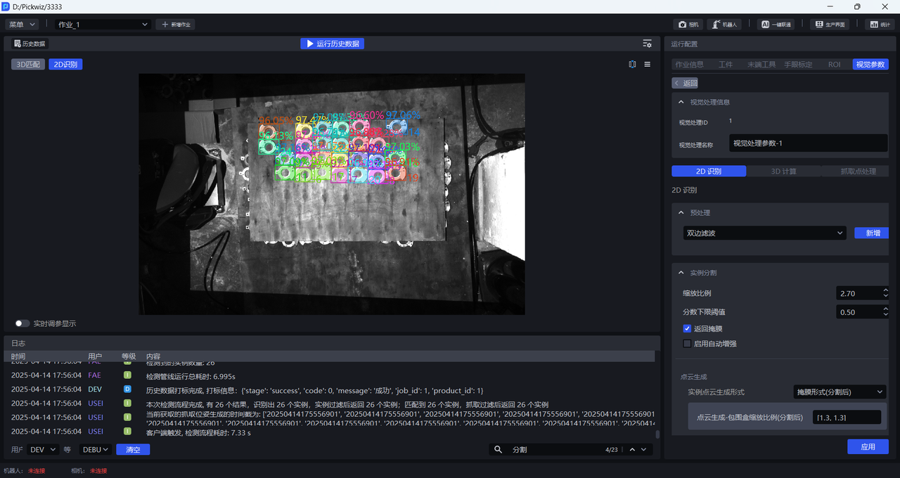
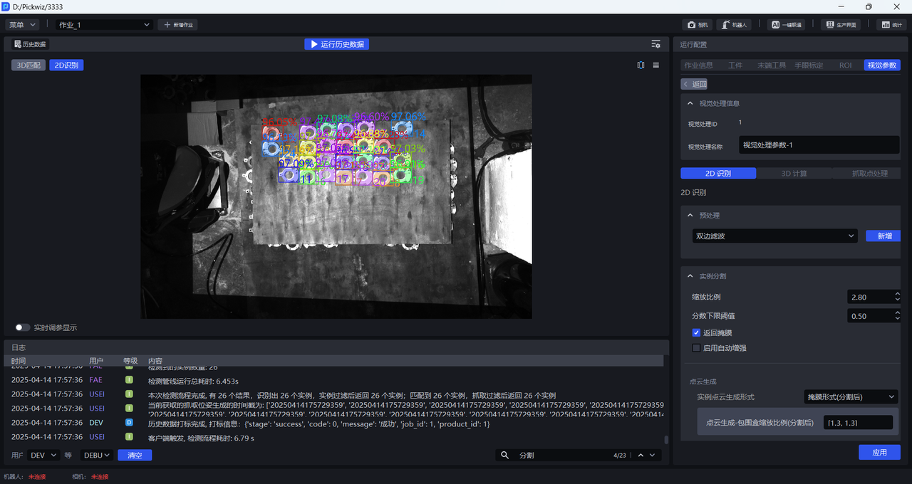

- If the actual scene does not require high picking accuracy, you can select a scaling ratio with a good detection effect within the range [0.33,3]. If the actual scene requires higher picking accuracy, further refine the scaling ratio range and adjust it with a smaller step size until the scaling ratio with the best detection effect is found.
1.2.2 Lower Confidence Threshold
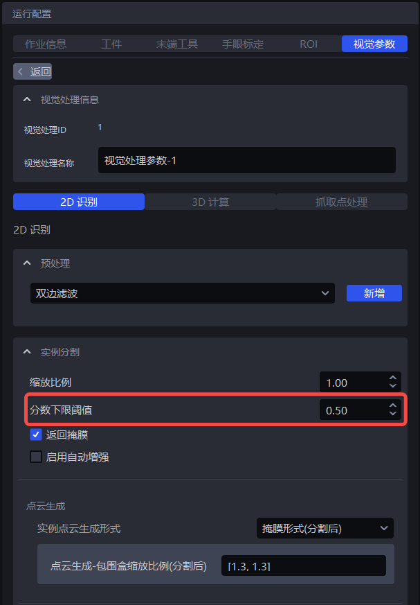
- Function
Retain only recognition results whose Deep Learning model score is higher than the lower Confidence threshold
- Use Case
Adjust this function when the instances enclosed by the detection results do not match expectations
- Parameter Description
Default value: 0.5
Value range: [0.01, 1.00]
Tuning
- If the model detects too few instances, reduce this threshold. If the value is too small, it may affect the accuracy of image recognition.
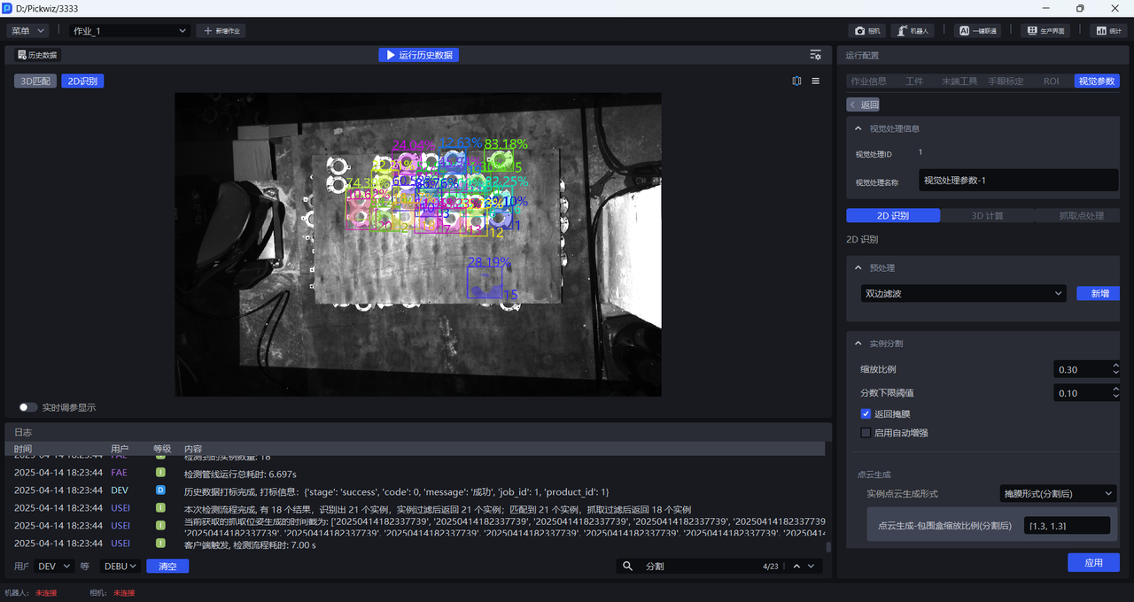
- If an excessively small lower Confidence threshold causes incorrect instances to be detected and you need to remove them, increase this threshold. If the value is too large, the number of retained detection results may become zero, resulting in no output.
1.2.3 Enable Auto Enhancement
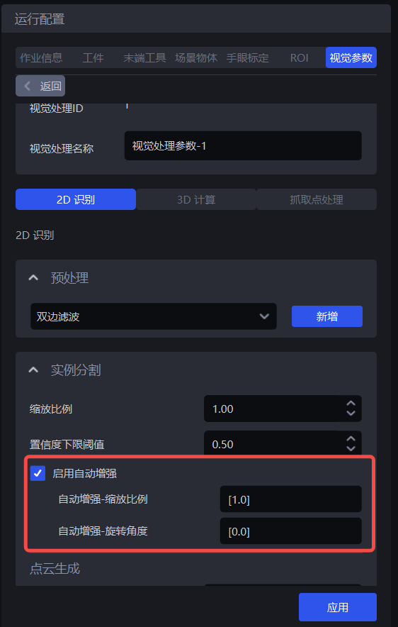
- Function
Combine all values in the input scaling ratios and rotation angles for inference, and return all results whose values after combination are greater than the configured lower Confidence threshold. This can improve model inference accuracy, but it increases processing time.
- Use Case
Used when a single scaling ratio cannot satisfy actual scene requirements, resulting in incomplete detection, or when target objects are placed at a large inclination angle.
- Example
If Auto Enhancement - Scaling Ratio is set to [0.8, 0.9, 1.0] and Auto Enhancement - Rotation Angle is set to [0, 90.0], the values in the scaling ratios and rotation angles are combined pairwise. The model internally generates 6 image variants for inference, then merges the 6 inference results and outputs those greater than the lower Confidence threshold.
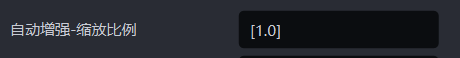
Auto Enhancement - Scaling Ratio
- Function
Scale the original image multiple times and perform inference multiple times, then output the aggregated inference result
- Use Case
Used when a single scaling ratio cannot satisfy actual scene requirements, resulting in incomplete detection
- Parameter Description
Default value: [1.0]
Value range: the range for each scaling ratio is [0.1, 3.0]
Multiple scaling ratios can be set, separated by English commas
- Tuning
Enter multiple scaling ratios that produced good detection results in 1.2.1 Scaling Ratio
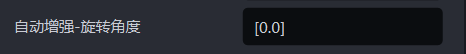
Auto Enhancement - Rotation Angle
- Function
Rotate the original image multiple times and perform inference multiple times, then output the aggregated inference result
- Use Case
Used when target object placement deviates significantly from the coordinate axes
- Parameter Description
Default value: [0.0]
Value range: the range for each rotation angle is [0, 360]
Multiple rotation angles can be set, separated by English commas
- Tuning
Adjust Auto Enhancement - Rotation Angle according to the target object angle in the actual scene. The inclination angle can be judged based on sack patterns and bag opening shapes, or on carton edges and brand marks.
1.3 Point Cloud Generation
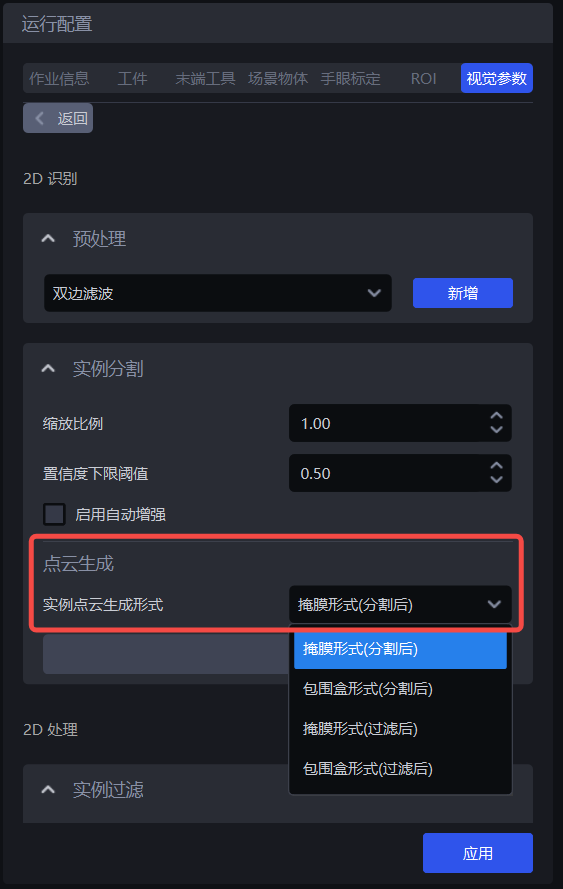
| Instance Point Cloud generation format | Mask format (after segmentation) | — | Generate Point Clouds using segmented instance Masks |
| Bounding box format (after segmentation) | Bounding box scaling ratio (after segmentation) | Generate Point Clouds using segmented instance bounding boxes | |
| Whether color is needed when generating Point Clouds (after segmentation) | Whether the generated instance Point Cloud needs attached color | ||
| Mask format (after filtering) | — | Generate Point Clouds using filtered instance Masks | |
| Bounding box format (after filtering) | Bounding box scaling ratio (after filtering) | Generate Point Clouds using filtered instance bounding boxes | |
| Whether color is needed when generating Point Clouds (after filtering) | Whether the generated instance Point Cloud needs attached color |
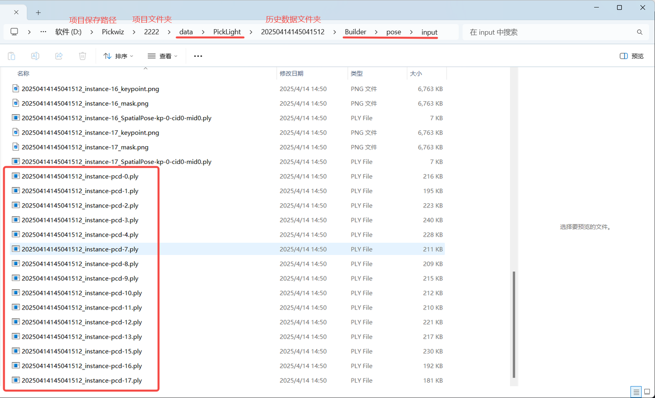
If acceleration is not required, there is no need to use the Instance Filtering function. Use Mask format (after segmentation) or Bounding box format (after segmentation) to generate instance Point Clouds. The generated instance Point Clouds can be viewed in the \project name\data\PickLight\historical data timestamp\Builder\pose\input folder under the project storage folder;
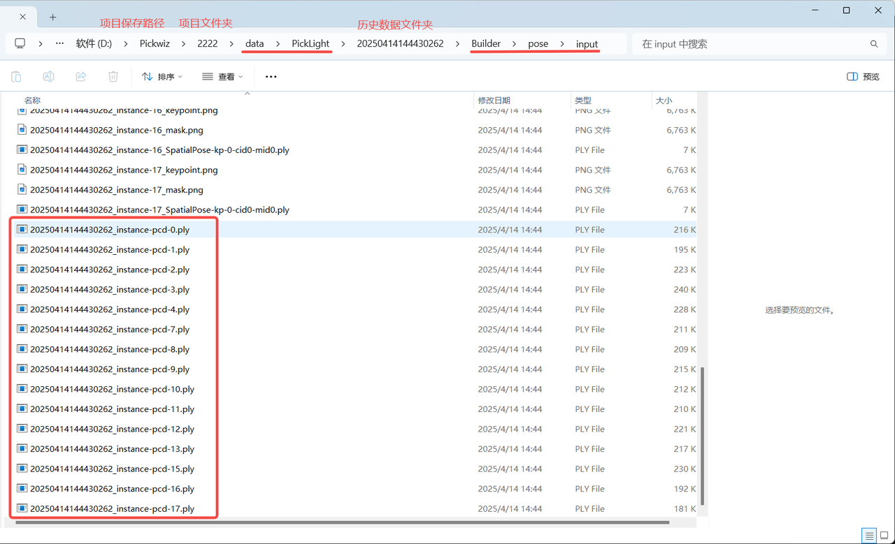
If acceleration is required, you can use the Instance Filtering function to filter instances, and use Mask format (after filtering) or Bounding box format (after filtering) to generate instance Point Clouds. The generated instance Point Clouds can be viewed in the \project name\data\PickLight\historical data timestamp\Builder\pose\input folder under the project storage folder
1.4 Instance Filtering
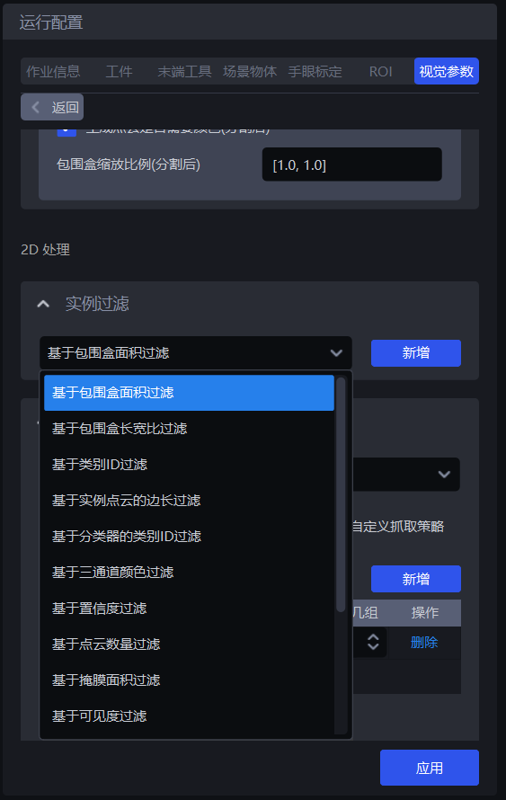
1.4.1 Filter Based on Bounding Box Area
- Function Description
Filter based on the pixel area of the bounding boxes of detected instances.
- Use Case
Suitable for scenarios where the bounding box areas of instances differ greatly. By setting upper and lower limits for the bounding box area, image noise can be filtered out, improving image recognition accuracy and avoiding additional processing time caused by noise.
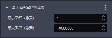
- Parameter Description
| Parameter | Description | Default Value | Parameter Range | Unit |
|---|---|---|---|---|
| Minimum area (pixels) | This parameter is used to set the minimum filter area of the bounding box. Instances whose bounding box area is smaller than this value will be filtered out | 1 | [1, 10000000] | pixels |
| Maximum area (pixels) | This parameter is used to set the maximum filter area of the bounding box. Instances whose bounding box area is larger than this value will be filtered out | 10000000 | [2, 10000000] | pixels |
- Example
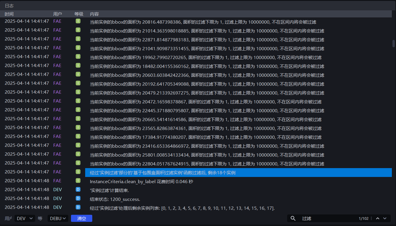
Run with the default values. You can view the bounding box area of each instance in the log, as shown below.
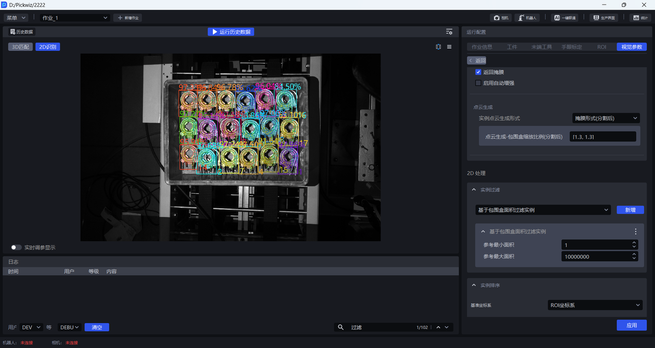
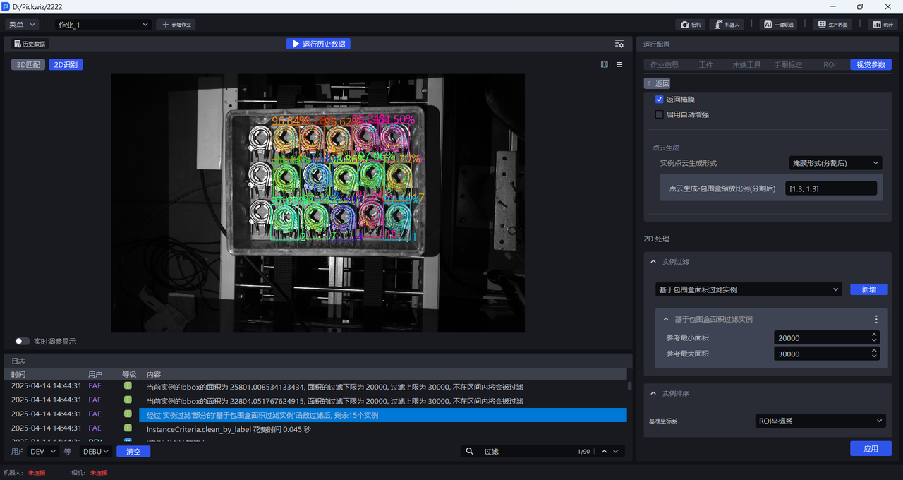
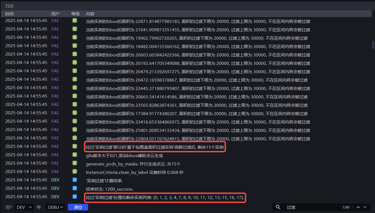
Adjust Minimum area and Maximum area according to the bounding box area of each instance. For example, if Minimum area is set to 20000 and Maximum area is set to 30000, instances with a pixel area smaller than 20000 or larger than 30000 will be filtered out. The instance filtering process can be viewed in the log.
1.4.2 Filter Based on Bounding Box Aspect Ratio
- Function Description
Instances whose bounding box aspect ratios are outside the specified range will be filtered out
- Use Case
Suitable for scenarios where the bounding box aspect ratios of instances differ greatly
- Parameter Description
| Parameter | Description | Default Value | Parameter Range |
|---|---|---|---|
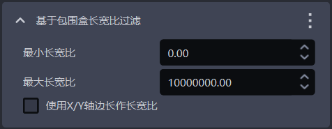
| Minimum aspect ratio | The minimum value of the bounding box aspect ratio. Instances whose bounding box aspect ratio is lower than this value will be filtered out | 0 | [0, 10000000] |
| Maximum aspect ratio | The maximum value of the bounding box aspect ratio. Instances whose bounding box aspect ratio is higher than this value will be filtered out | 10000000 | [0, 10000000] |
| Use X/Y-axis side lengths as the aspect ratio | By default, this option is cleared, and the ratio of the longer side to the shorter side of the bounding box is used as the aspect ratio, which is suitable when the lengths of the longer and shorter sides of the bounding box differ greatly; when selected, the ratio of the side lengths of the bounding box along the X-axis and Y-axis in the pixel coordinate system is used as the aspect ratio. This is suitable when the ratios of the longer side to the shorter side are similar for most normal instance bounding boxes, but some abnormally recognized instance bounding boxes differ greatly in the ratio of their X-axis length to Y-axis length. | Cleared | / |
1.4.3 Filter Instances Based on Category ID
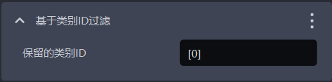
- Function Description
Filter according to instance categories
- Use Case
Suitable for scenarios where incoming materials contain multiple types of target objects
- Parameter Description
| Parameter | Description | Default Value |
|---|---|---|
| Retained category IDs | Instances whose category IDs are in the list are retained; instances whose category IDs are not in the list are filtered out | [0] |
- Example
1.4.4 Filter Based on Instance Point Cloud Side Length
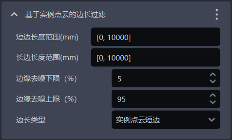
- Function Description
Filter according to the long side and short side of the instance Point Cloud
- Use Case
Suitable for scenarios where the distances of instance Point Clouds along the X-axis or Y-axis differ greatly. By setting the distance range of instance Point Clouds, image noise can be filtered out, improving image recognition accuracy and avoiding additional processing time caused by noise.
- Parameter Description
| Parameter | Description | Default Value | Parameter Range | Unit |
|---|---|---|---|---|
| Short-side length range (mm) | The side length range of the short side of the Point Cloud | [0, 10000] | [0, 10000] | mm |
| Long-side length range (mm) | The side length range of the long side of the Point Cloud | [0, 10000] | [0, 10000] | mm |
| Lower bound of edge denoising (%) | Extract the lower percentage bound of X/Y values (Camera coordinate system) in the instance Point Cloud, and remove Point Clouds outside the upper and lower bounds to prevent noise from affecting length calculation | 5 | [0, 100] | / |
| Upper bound of edge denoising (%) | Extract the upper percentage bound of X/Y values (Camera coordinate system) in the instance Point Cloud, and remove Point Clouds outside the upper and lower bounds to prevent noise from affecting length calculation | 95 | [0, 100] | / |
| Side length type | Filter according to the long side and short side of the instance Point Cloud. Instances whose long-side or short-side length is outside the range will be filtered out | Short side of instance Point Cloud | Short side of instance Point Cloud; long side of instance Point Cloud; long and short sides of instance Point Cloud | / |
- Example
1.4.5 Filter Category ID Based on Classifier
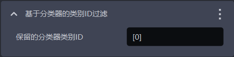
- Function Description
Filter instances based on the classifier category ID. Instances not in the reference categories will be filtered out.
- Use Case
In multi-category target object scenarios, the vision model may detect multiple types of target objects, but the actual task may require only one category. In this case, this function can be used to filter out unnecessary target objects
- Parameter Description
The default value is [0], which means that instances with category ID 0 are retained by default. Instances whose category IDs are not in the list will be filtered out.
1.4.6 Filter Based on Three-channel Color
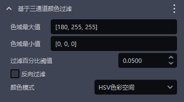
- Function Description
Instances can be filtered out using three-channel color thresholds (HSV or RGB).
- Use Case
Suitable when incorrect instances and correct instances have clearly distinguishable colors.
- Parameter Description
| Parameter | Description | Default Value | Value Range |
|---|---|---|---|
| Maximum color range value | Maximum color value | [180,255,255] | [[0,0,0],[255,255,255]] |
| Minimum color range value | Minimum color value | [0,0,0] | [[0,0,0],[255,255,255]] |
| Filtering percentage threshold | Color pass-rate threshold | 0.05 | [0,1] |
| Reverse filtering | When selected, remove instances whose proportion outside the color range is lower than the threshold; when cleared, remove instances whose proportion within the color range in the instance image is lower than the threshold | Cleared | / |
| Color mode | The color space selected for color filtering | HSV color space | RGB color space; HSV color space |
- Example
1.4.7 Filter Based on Confidence
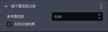
- Function Description
Filter according to the Confidence scores of instances
- Use Case
Suitable for scenarios where the Confidence scores of instances differ greatly
- Parameter Description
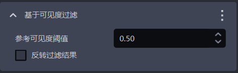
| Parameter | Description | Default Value | Parameter Range |
|---|---|---|---|
| Reference Confidence threshold | Retain instances whose Confidence is greater than the threshold, and filter out instances whose Confidence is lower than the threshold. | 0.5 | [0,1] |
| Reverse filtering result | After reversal, retain instances whose visibility Confidence is lower than the threshold, and filter out instances whose Confidence is greater than the threshold. | Cleared | / |
- Example
1.4.8 Filter Based on Point Cloud Quantity
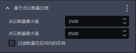
- Function Description
Filter according to the quantity of downsampled instance Point Cloud points
- Use Case
Suitable when the instance Point Cloud contains a large amount of noise
- Parameter Description
| Parameter | Description | Default Value | Parameter Range |
|---|---|---|---|
| Minimum Point Cloud quantity | The minimum number of Point Cloud points | 3500 | [1, 10000000] |
| Maximum Point Cloud quantity | The maximum number of Point Cloud points | 8500 | [2, 10000000] |
| Filter instances whose quantity is within the interval | When selected, filter out instances whose Point Cloud quantity is within the interval between the minimum and maximum values; when cleared, filter out instances whose Point Cloud quantity is outside the interval | Cleared | / |
1.4.9 Filter Based on Mask Area
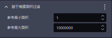
- Function Description
Filter image Masks according to the sum of Mask pixels (that is, the pixel area) of detected instances.
- Use Case
Suitable for scenarios where instance Mask areas differ greatly. By setting upper and lower limits for the Mask area, noise in image Masks can be filtered out, improving image recognition accuracy and avoiding additional processing time caused by noise.
- Parameter Description
| Parameter Name | Description | Default Value | Parameter Range | Unit |
|---|---|---|---|---|
| Reference minimum area | This parameter is used to set the minimum filter area of the Mask. Instances whose Mask area is smaller than this value will be filtered out | 1 | [1, 10000000] | pixels |
| Reference maximum area | This parameter is used to set the maximum filter area of the Mask. Instances whose Mask area is larger than this value will be filtered out | 10000000 | [2, 10000000] | pixels |
- Example
1.4.10 Filter Based on Visibility
- Function Description
Filter according to the visibility scores of instances
- Use Case
Suitable for scenarios where the visibility scores of instances differ greatly
- Parameter Description
| Parameter | Description | Default Value | Parameter Range |
|---|---|---|---|
| Reference visibility threshold | Retain instances whose visibility is greater than the threshold, and filter out instances whose visibility is lower than the threshold. Visibility is used to judge how visible an instance is in the image; the more the target object is occluded, the lower the visibility. | 0.5 | [0,1] |
| Reverse filtering result | After reversal, retain instances whose visibility is lower than the threshold, and filter out instances whose visibility is greater than the threshold. | Cleared | / |
1.4.11 Filter Instances with Overlapping Bounding Boxes
- Function Description
Filter instances whose bounding boxes intersect and overlap
- Use Case
Suitable for scenarios where the bounding boxes of instances intersect with each other
- Parameter Description
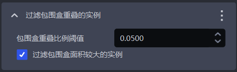
| Parameter | Description | Default Value | Parameter Range |
|---|---|---|---|
| Bounding box overlap ratio threshold | The threshold for the ratio of the intersecting area of bounding boxes to the area of the instance bounding box | 0.05 | [0, 1] |
| Filter the instance with the larger bounding box area | When selected, filter out the instance with the larger area among two instances whose bounding boxes intersect; when cleared, filter out the instance with the smaller area among the two intersecting instances | Selected | / |
- Example
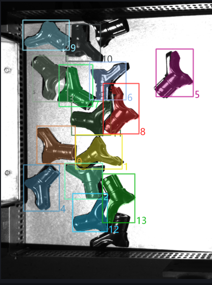
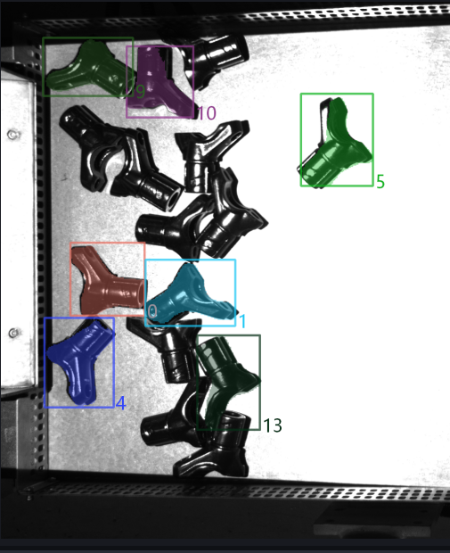
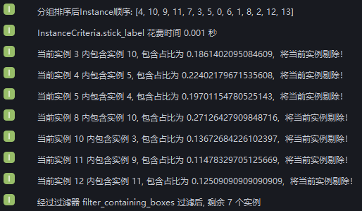
New: filter enclosed instances. Run with the default values and view the bounding box intersection status of instances in the log. After instance filtering, 2 instances remain.
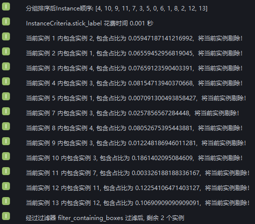
From the log, it can be seen that 12 instances were filtered out because their bounding boxes intersected, leaving 2 instances whose bounding boxes do not intersect
Set Bounding box overlap ratio threshold to 0.1 and select Filter the instance with the larger bounding box area. View the instance filtering process in the log: 9 instances were filtered out because the ratio of the intersecting area of their bounding boxes to their own bounding box area was greater than 0.1; 3 instances were retained because that ratio was less than 0.1; and 2 instances had no bounding box intersection.
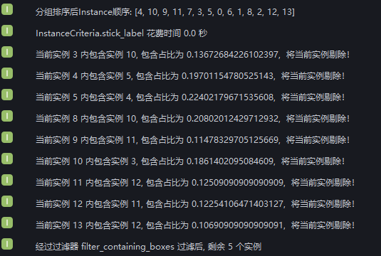
Set Bounding box overlap ratio threshold to 0.1 and clear Filter the instance with the larger bounding box area. View the instance filtering process in the log: for 9 instances, the ratio of the intersecting area of their bounding boxes to their own bounding box area was greater than 0.1, but 2 of them were retained because their bounding box area was smaller than that of the intersecting instance, so 7 instances were filtered out. Another 3 instances were retained because that ratio was less than 0.1, and 2 instances had no bounding box intersection.
1.4.12 [Advanced] Filter Instances with Uneven Masks Based on the Mask/Enclosing Polygon Area Ratio
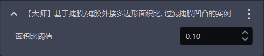
- Function Description
Calculate the ratio of the Mask area to the area of the Mask's enclosing polygon. If the ratio is smaller than the configured threshold, the instance will be filtered out.
- Use Case
Suitable for cases where the target object Mask has serrations or bumps.
- Parameter Description
| Parameter | Description | Default Value | Value Range |
|---|---|---|---|
| Area ratio threshold | The threshold for the Mask/convex hull area ratio. If the ratio is smaller than the configured threshold, the instance will be filtered out. | 0.1 | [0,1] |
1.4.13 [Advanced] Filter Based on Average Point Cloud Distance
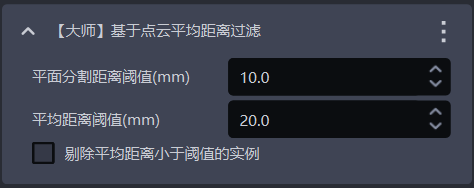
- Function Description
Filter based on the average distance from points in the Point Cloud to the fitted plane, and remove uneven instance Point Clouds.
- Use Case
Suitable for scenarios where the Point Cloud of a planar target object is bent.
- Parameter Description
| Parameter | Description | Default Value | Parameter Range | Unit |
|---|---|---|---|---|
| Plane segmentation distance threshold (mm) | Extract a plane from the bent instance Point Cloud. Points whose distance to the plane is smaller than this threshold are regarded as points on the plane. | 10 | [-1000, 1000] | mm |
| Average distance threshold (mm) | The average distance from points in the instance Point Cloud to the extracted plane | 20 | [-1000, 1000] | mm |
| Filter instances whose average distance is smaller than the threshold | When selected, instances whose average distance from points to the extracted plane is smaller than the average distance threshold are filtered out; when cleared, instances whose average distance from points to the extracted plane is greater than the average distance threshold are filtered out. | Cleared | / | / |
1.4.14 [Advanced] Filter Occluded Instances Based on the Mask/Bounding Box Area Ratio
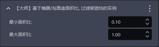
- Function Description
Calculate the Mask-to-bounding-box area ratio. Instances whose ratios are outside the minimum and maximum range will be filtered out.
- Use Case
Used to filter instances of occluded target objects.
- Parameter Description
Conversely, it may be occluded.
| Parameter | Description | Default Value | Value Range |
|---|---|---|---|
| Minimum area ratio | The lower bound of the Mask/bounding-box area ratio range. The smaller the ratio, the more severely the instance is occluded. | 0.1 | [0,1] |
| Maximum area ratio | The upper bound of the Mask/bounding-box area ratio range. The closer the ratio is to 1, the less the instance is occluded. | 1.0 | [0,1] |
1.4.15 [Advanced] Determine Whether All Top-layer Instances Have Been Fully Detected
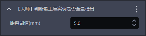
- Function Description
This is one of the error-proofing mechanisms. It determines whether all top-layer instances have been detected. If there are any undetected top-layer instances, an error is reported and the Workflow ends.
- Use Case
Suitable for scenarios where one image is used for multiple picks, or picking must be performed in sequence, to prevent missed picks caused by incomplete instance detection from affecting subsequent tasks.
- Parameter Description
| Parameter | Description | Default Value | Parameter Range | Unit | Tuning |
|---|---|---|---|---|---|
| Distance threshold | Used to determine whether a target object is on the top layer. If the distance between a point and the highest point of the target object's Point Cloud is smaller than the distance threshold, the point is considered part of the top-layer Point Cloud; otherwise, it is not. | 5 | [0.1, 1000] | mm | Should be smaller than the height of the target object |
1.5 Instance Sorting
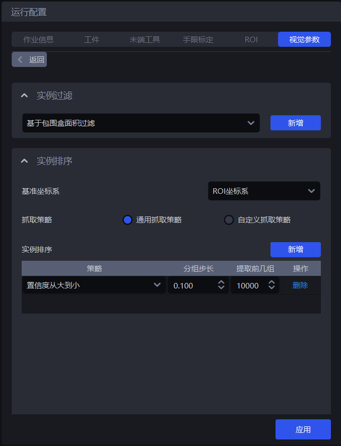
- Function Description
Group, sort, and extract instances according to the selected strategy
- Use Case
Common to depalletizing, random picking, and ordered loading and unloading scenarios
If sorting is not required, you do not need to configure a specific strategy.
1.5.1 Reference Coordinate System
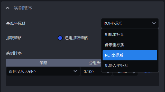
- Function Description
Set a unified coordinate system for all instances to group and sort them
- Use Case
Common to depalletizing scenarios, random picking scenarios, and ordered loading and unloading scenarios
When using coordinate-related strategies, the reference coordinate system should be set first
- Parameter Description
| Parameter | Description | Illustration |
|---|---|---|
| Camera coordinate system | The origin of the coordinate system is above the target object, and the positive Z-axis points downward; the XYZ values are the values of the target object's center point in this coordinate system | 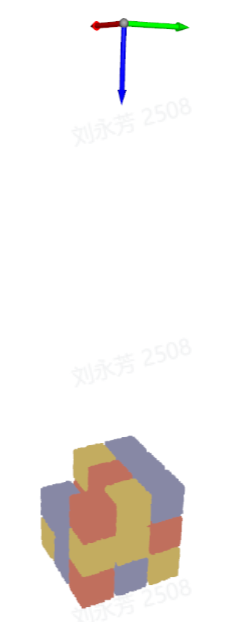 |
| ROI coordinate system | The origin of the coordinate system is approximately at the center of the stack, and the positive Z-axis points upward; the XYZ values are the values of the target object's center point in this coordinate system | 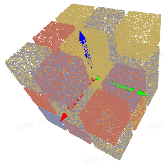 |
| Robot arm coordinate system | The origin of the coordinate system is on the robot arm itself, and the positive Z-axis generally points upward; the XYZ values are the values of the target object's center point in this coordinate system | 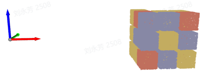 |
| Pixel coordinate system | The origin of the coordinate system is at the top-left point of the RGB image. It is a 2D planar coordinate system; the X and Y values are the x and y values of the bbox recognition box, and Z is 0 | 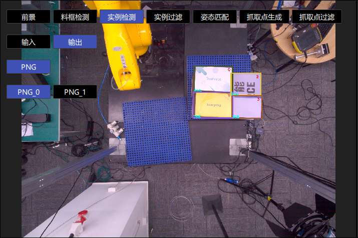 |
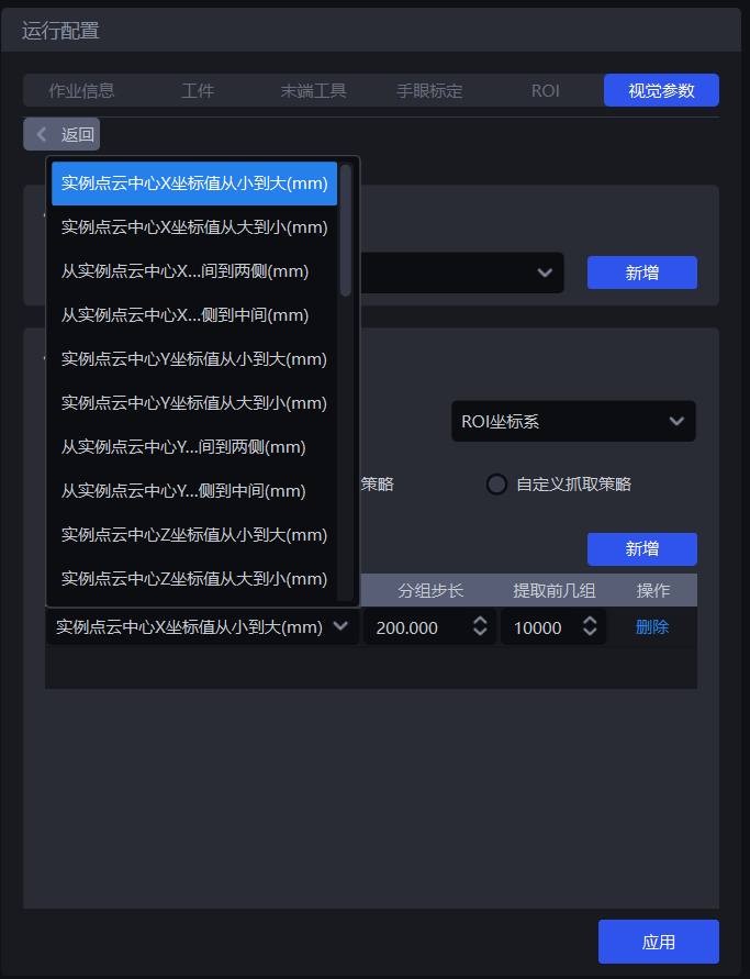
1.5.2 General Picking Strategy
- Parameter Description
| Parameter | Description | Default Value |
|---|---|---|
| Strategy | Select which value to use for grouping and sorting and how to sort, including the XYZ coordinate values of the instance Point Cloud center, the bounding box aspect ratio, the distance between the instance Point Cloud center and the ROI center, and more. Multiple strategies can be superimposed and are executed in sequence. | Instance Point Cloud center X-coordinate value from small to large (mm) |
| Grouping step size | According to the selected strategy, instances are divided into several groups based on the step size. The grouping step size is the interval between two groups. For example, if the strategy "Instance Point Cloud center Z-coordinate value from large to small (mm)" is selected, the Z coordinates of all instance Point Cloud centers are sorted from large to small and then grouped by step size; the corresponding instances are also divided into several groups. | / |
| Number of leading groups to extract | How many groups of instances need to be retained after grouping and sorting | 10000 |
| Strategy name* | Description | Grouping step size | Number of leading groups to extract | |
|---|---|---|---|---|
| Default Value | Value Range | Default Value | ||
| Instance Point Cloud center XYZ coordinate values from large to small / from small to large (mm) | Use the XYZ coordinate values of each instance's Point Cloud center for grouping and sorting The reference coordinate system should be set before using this strategy for sorting | 200.000 | (0, 10000000] | 10000 |
| From the middle to both sides / from both sides to the middle along the XY axes of the instance Point Cloud center (mm) | Use the XY coordinate values of each instance's Point Cloud center for grouping and sorting in the direction of "from the middle to both sides" or "from both sides to the middle" The reference coordinate system should be set before using this strategy for sorting | 200.000 | (0, 10000000] | 10000 |
| Bounding box center XY coordinate values from large to small / from small to large (mm) | Use the XY coordinate values of each instance's bounding box center in the pixel coordinate system for grouping and sorting | 200.000 | (0, 10000000] | 10000 |
| Bounding box aspect ratio from large to small / from small to large | Use the ratio of the bounding box's long side to short side for grouping and sorting | 1 | (0, 10000] | 10000 |
| From the middle to both sides / from both sides to the middle along the XY axes of the bounding box center (mm) | Use the XY coordinate values of the bounding box center for grouping and sorting in the direction of "from the middle to both sides" or "from both sides to the middle" | 200.000 | (0, 10000000] | 10000 |
| Target Object type ID from large to small / from small to large | Use the Target Object type ID for grouping and sorting. Suitable for multi-category target object scenarios. | 1 | [1, 10000] | 10000 |
| Local feature ID from large to small / from small to large | Use the local feature ID for grouping and sorting | 1 | [1, 10000] | 10000 |
| Confidence from large to small / from small to large | Use the Confidence of each instance for grouping and sorting | 1 | (0, 1] | 10000 |
| Visibility from small to large / from large to small | Use the visibility of each instance for grouping and sorting | 1 | (0, 0.1] | 10000 |
| Mask area from large to small / from small to large | Use the Mask area of each instance for grouping and sorting | 10000 | [1, 10000000] | 10000 |
| Distance from instance Point Cloud center to ROI center from near to far / from far to near (mm) | Use the distance between each instance's Point Cloud center and the center of the ROI coordinate system for grouping and sorting | 200.000 | (0, 10000000] | 10000 |
| Distance from instance Point Cloud center to robot coordinate origin from near to far / from far to near (mm) | Use the distance between each instance's Point Cloud center and the origin of the Robot coordinate system for grouping and sorting | 200.000 | (0, 10000000] | 10000 |
- Example
1.5.3 Custom Picking Strategy
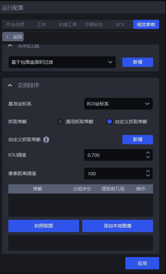
(1) Function Description
Switch Picking Strategy to Custom Picking Strategy, and click Add to add one custom picking strategy.
Use a custom picking strategy to define the order in which each target object is picked. If it is difficult to achieve picking with the general picking strategy, or if suitable parameters are difficult to tune due to Point Cloud noise and other issues, consider using a custom picking strategy
Custom picking strategies are suitable for depalletizing scenarios and ordered loading and unloading scenarios, but not for random picking scenarios, because target objects using a custom picking strategy must be ordered (that is, the order of target objects is fixed)
A custom picking strategy can only be used in combination with a single general picking strategy, and the strategy can only select Z-coordinate values from small to large
(2) Parameter Description
| Parameter | Description | Default Value | Value Range | Tuning |
|---|---|---|---|---|
| IoU threshold | Represents the overlap threshold between the annotated bbox and the detected bbox. The overlap is used to determine which image's sorting order should be selected for the current target object instance sorting. | 0.7 | [0,1] | The larger the threshold, the stricter the matching and the worse the anti-interference capability. Tiny shape or position changes may cause matching failure, possibly matching the wrong custom strategy and sorting in the wrong order. |
| Pixel distance threshold | Represents the size difference between the bbox that can be matched and the detected bbox. | 100 | [0,1000] | The smaller the threshold, the stricter the matching and the better the anti-interference capability. If the placement of target objects across different layers is relatively similar, the wrong custom strategy may still be matched, resulting in an incorrect sorting order. |
(3) Select the Reference Coordinate System
When using a custom picking strategy, only the Camera coordinate system or the pixel coordinate system can be selected
If there are multiple layers of target objects, select the Camera coordinate system; if there is only one layer, select the pixel coordinate system
(4) Strategy, Grouping Step Size, and Number of Leading Groups to Extract
| Parameter | Description | Default Value |
|---|---|---|
| Strategy | Only Instance Point Cloud center Z-coordinate value from large to small / from small to large (mm) can be selected | / |
| Grouping step size | According to the strategy of sorting Z coordinates from small to large, sort the Z coordinates of instances from small to large and divide the instances into several groups based on the step size | 10000 |
| Number of leading groups to extract | How many groups of instances need to be retained after grouping and sorting | 10000 |
(5) Capture Images / Add Local Images
Click Capture Images to obtain images from the currently connected Camera, or click Add Local Images to import images locally. For each layer or each different placement pattern of target objects, one image is required. If every layer is the same, only one image is needed. Right-click an image to delete it.
On the acquired image, press and hold the left mouse button and drag to annotate bbox boxes. Press the DELETE key to remove annotated bbox boxes one by one.
2. 3D Computation
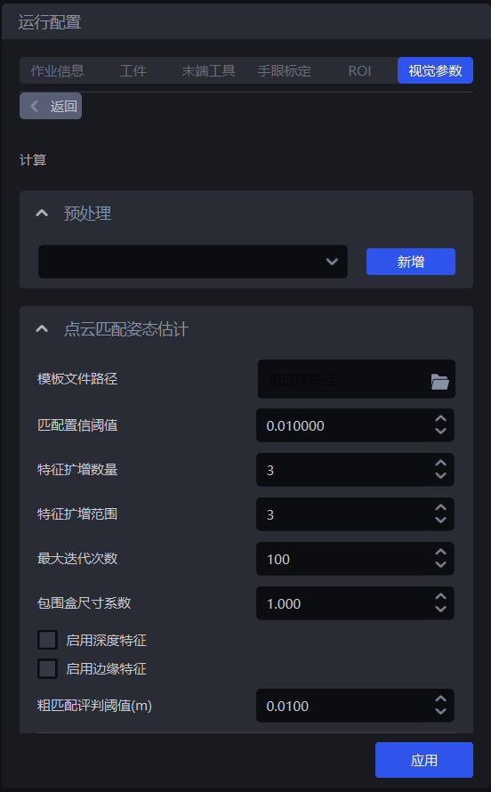
2.1 Preprocessing
Preprocessing in 3D Computation means processing the 3D Point Cloud before performing pose estimation on instances and generating Pick Points. In the ordered loading and unloading scenario for planar target objects (parallelized), the 3D Point Cloud does not need to be processed.
2.2 Point Cloud Matching Pose Estimation
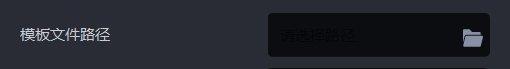
2.2.1 Template File Path
- Function
Upload the Point Cloud template to match it with the instance Point Cloud in the scene
- Use Case
Ordered loading and unloading scenario for planar target objects (parallelized)
- Tuning Instructions
This Point Cloud template must be created using the template generation script. The creation method is as follows:
- Copy the scene's 2D image, depth image, and Point Cloud image
(1) Select the timestamp of the historical data to copy
Select a timestamp folder from the PickLight historical data folder (for example, /home/xxx/PickLight/20240718201333036), and copy its full path for later use.
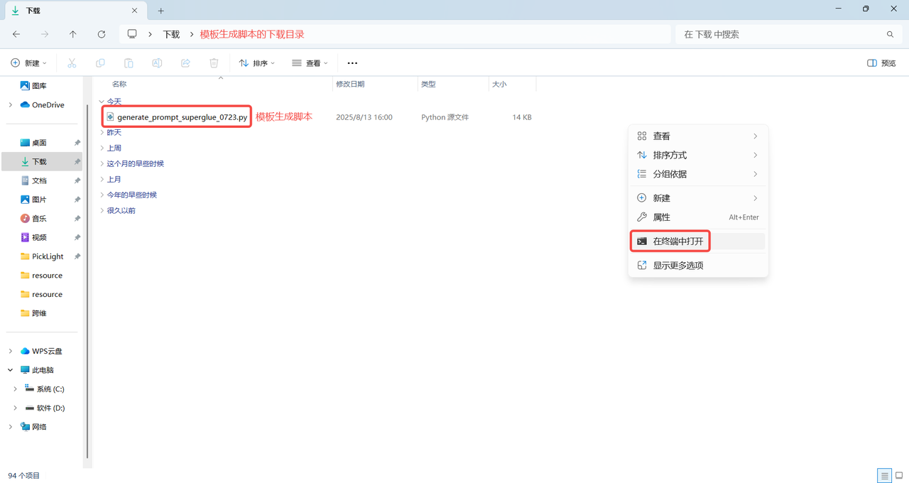
(2) Download the template generation script
Note:
The template generation script must match the software version. Otherwise, version incompatibility will cause Point Cloud template generation to fail.
The download directory of the template generation script cannot contain Chinese characters or special characters. It is recommended to store it in the default download directory C:
\Users\dex\Downloads
PickWiz version > =1.8.0 template generation script: click to view the full code
Template generation script

import argparse
import math
import os
import shutil
from copy import deepcopy
import cv2

import json
import numpy as np
import open3d as o3d
import torch
from kornia.filters import sobel as kornia_sobel

# from PickLight.Utils.Convertor import generate_mask_from_points
# from PickLight.Utils.Utility import FileOperation

try:
    import glia

    if not glia.__version__ >= "0.2.4":
        raise RuntimeError("Please upgrade glia to version 0.2.4 or later. Current version: {}").format(glia.__version__)
    from glia.dl.models.superglue import SuperGlueMatcher
except Exception:
    raise ImportError(f"Glia version is too low. Please upgrade Glia first. Current version: {glia.__version__}.\n")


from typing import Optional
def generate_mask_from_points(
    points: np.array,
    K: np.array,
    h: int,
    w: int,
    image: Optional[None] = None,
    kernel_size: Optional[int] = 5,
    iterations: Optional[int] = 1,
    auto_scale=4,
) -> np.array:
    """Given camera intrinsic parameters K, image size hxw, and marked points,
    this function is to project marked points to image plane and generate mask.

    Args:
        points (np.array): marked points with size n x 3.
        K (np.array): camera intrinsic parameters, 3 x 3.
        h (int): image height.
        w (int): image width.
        image (Optional[cv2.mat], optional): If provided, this function will additionally
        provide mask on this image. Defaults to None.
        kernel_size (Optional[int], optional): To avoid uncontinuous mask,
        use morphology kernel. This parameter defines kernel size. Defaults to 5.

    Returns:
        np.array: mask given by points, on h x w canvas.
    """

    K_ = deepcopy(K)
    K_[:2, :] = K_[:2, :] / auto_scale

    rvec, tvec = cv2.Rodrigues(np.eye(3))[0], np.zeros((3, 1))
    image_points, _ = cv2.projectPoints(
        points,
        rvec,
        tvec,
        K_,
        np.zeros(
            5,
        ),
    )
    kernel = cv2.getStructuringElement(cv2.MORPH_RECT, (kernel_size, kernel_size))
    pixel_indices = image_points.squeeze(1).astype(np.int32)
    bool_w = np.logical_and(pixel_indices[:, 0] > 0, pixel_indices[:, 0] < int(w / auto_scale))
    bool_h = np.logical_and(pixel_indices[:, 1] > 0, pixel_indices[:, 1] < int(h / auto_scale))
    valid_pixel_indices = pixel_indices[np.logical_and(bool_w, bool_h), :]
    mask = np.zeros((int(h / auto_scale), int(w / auto_scale), 1))
    mask[valid_pixel_indices[:, 1], valid_pixel_indices[:, 0], ...] = 1
    dilated_mask = cv2.dilate(mask, kernel, iterations)
    dilated_mask = cv2.resize(dilated_mask, (w, h), interpolation=cv2.INTER_NEAREST)
    if image is None:
        return dilated_mask
    else:
        return dilated_mask, np.multiply(image, np.expand_dims(dilated_mask, -1))


def file_transfer(args):
    input_dir = args.data_dir
    output_dir = args.output_dir
    os.makedirs(output_dir, exist_ok=True)
    # RGB+D
    try:
        for root, dirs, files in os.walk(input_dir):
            target_path = os.path.join(root, 'Builder', 'foreground', 'input')
            if os.path.exists(target_path):
                for file in os.listdir(target_path):
                    if file.endswith('.png') or file.endswith('.tiff'):
                        full_file_path = os.path.join(target_path, file)
                        shutil.copy(full_file_path, output_dir)
                        print(f'Copied: {file}')
    except Exception as e:
        raise ValueError(f"Check whether the Builder/foreground/input folder exists under the path {input_dir}. {e}")
    # PCD
    try:
        for root, dirs, files in os.walk(input_dir):
            target_path = os.path.join(root, 'Builder', 'foreground', 'input')
            if os.path.exists(target_path):
                # Iterate through all files in the target path
                for file in os.listdir(target_path):
                    if file.endswith('.ply'):
                        full_file_path = os.path.join(target_path, file)
                        shutil.copy(full_file_path, output_dir)
                        print(f'Copied: {file}')
    except Exception as e:
        raise ValueError(f"Check whether the Builder/foreground/output folder exists under the path {input_dir}. {e}")
    # json
    try:
        for root, dirs, files in os.walk(input_dir):
            target_path = os.path.join(root, 'Builder', 'foreground', 'input')
            if os.path.exists(target_path):
                # Iterate through all files in the target path
                for file in os.listdir(target_path):
                    if file.endswith('.json'):
                        full_file_path = os.path.join(target_path, file)
                        shutil.copy(full_file_path, output_dir)
                        print(f'Copied: {file}')
    except Exception as e:
        raise ValueError(f"Check whether the ResourceManager folder exists under the path {input_dir}. {e}")


def search_depth_values(indices, depth_mask, search_radius=3):
    """
    Search for a nearby non-zero depth value and fill it into the depth mask.

    Args:
    - indices: Index array of keypoints, with shape (N, 2)
    - depth_mask: Initial depth mask, with shape (H, W)
    - search_radius: Search radius, default is 3

    Returns:
    - depth_values: Depth value found for each keypoint
    """
    depth_values = np.full(indices.shape[0], -1, dtype=np.float32)  # Initialize to -1 to indicate that no non-zero depth value was found
    for idx, (x, y) in enumerate(indices):
        if depth_mask[y, x] == 0:
            xmin, xmax = max(0, x - search_radius), min(depth_mask.shape[0], x + search_radius + 1)
            ymin, ymax = max(0, y - search_radius), min(depth_mask.shape[1], y + search_radius + 1)
            search_area = depth_mask[ymin:ymax, xmin:xmax]
            non_zero = search_area[search_area != 0]
            if non_zero.size > 0:
                depth_values[idx] = non_zero[0]
        else:
            depth_values[idx] = depth_mask[y, x]

    return depth_values

def rotate_pcd(pcd, angle, original_center=None):

    # Calculate the original center
    if original_center is None:
        original_center = pcd.get_center()
    # print("Original center coordinates:", np.round(original_center, 3))

    # Center the point cloud (translate to the origin)
    t_1 = np.array([
        [1, 0, 0, -original_center[0]],
        [0, 1, 0, -original_center[1]],
        [0, 0, 1, -original_center[2]],
        [0, 0, 0, 1]
    ])

    # Rotate around the Z axis
    theta = np.radians(angle)
    cos_theta = np.cos(theta)
    sin_theta = np.sin(theta)
    t_2 = np.array([
        [cos_theta, -sin_theta, 0, 0],
        [sin_theta, cos_theta, 0, 0],
        [0, 0, 1, 0],
        [0, 0, 0, 1]
    ])

    # Translate back to the original center
    t_3 = np.array([
        [1, 0, 0, original_center[0]],
        [0, 1, 0, original_center[1]],
        [0, 0, 1, original_center[2]],
        [0, 0, 0, 1]
    ])

    transform_all = np.dot(t_3, np.dot(t_2, t_1))
    # print(transform_all)
    pcd_final = deepcopy(pcd).transform(transform_all)
    # print("Final center:", np.round(pcd_final.get_center(), 3))

    return pcd_final, transform_all

def project_pcd_to_rgb(input_dir, output_dir, angle, auto_scale, mask_kernel_size, edge_kernel_size, index = 1, use_edge = False):
    os.makedirs(output_dir, exist_ok=True)

    cam_k_path = os.path.join(input_dir, "model_info_0.json")
    cam_k = json.load(open(cam_k_path))
    cam_k = cam_k["camera_param"]
    cam_k = np.asarray(cam_k).reshape(3, 3).astype(np.float32)

    pcd_path = os.path.join(input_dir, "model_0.ply")
    pcd = o3d.io.read_point_cloud(pcd_path)

    temp_img_path = os.path.join(input_dir, "temp_0.png")
    temp_img = cv2.imread(temp_img_path)

    project_img = np.zeros(temp_img.shape, dtype=np.uint8)
    project_depth = np.zeros(temp_img.shape[:2], dtype=np.float32)

    aabb = pcd.get_axis_aligned_bounding_box()
    aabb_center = (aabb.get_min_bound() + aabb.get_max_bound()) / 2
    pcd_transformed, transform_all = rotate_pcd(pcd, angle, aabb_center)
    o3d.io.write_point_cloud(os.path.join(output_dir, f"model_{index}.ply"), pcd_transformed)
    f_json_data = open(os.path.join(output_dir, f"model_info_{index}.json"), "w+")
    json_saved_data = {}
    json_saved_data["camera_param"] = cam_k.tolist()
    json_saved_data["transform"] = transform_all.tolist()
    json_saved_data["angle"] = angle
    json_saved_data["use_edge"] = use_edge
    json_saved_data["mask_kernel_size"] = mask_kernel_size
    json_saved_data["edge_kernel_size"] = edge_kernel_size
    json.dump(json_saved_data, f_json_data, indent=4)
    f_json_data.close()

    rvec = np.array([0.0, 0.0, 0.0])  # Rotation vector
    tvec = np.array([0.0, 0.0, 0.0])  # Translation vector
    distortion_zeros = np.zeros((5, 1), dtype=np.float32)
    pcd_np = np.array(pcd_transformed.points)
    points_2d, _ = cv2.projectPoints(pcd_np, rvec, tvec, cam_k, distortion_zeros)
    points_2d = points_2d.squeeze(1).reshape(-1, 2)

    color_bgr = np.asarray(pcd_transformed.colors)[:,::-1]*255
    for i, pt in enumerate(points_2d):
        project_img[round(pt[1]), round(pt[0]), :] = color_bgr[i]
        project_depth[round(pt[1]), round(pt[0])] = pcd_np[i][2]

    mask = np.any(project_img != 0, axis=2)
    # Thresholding to separate black pixels
    project_img = cv2.cvtColor(project_img, cv2.COLOR_BGR2GRAY)
    if use_edge:
        project_img[mask] = 255
    project_img = cv2.morphologyEx(project_img, cv2.MORPH_CLOSE, np.ones((mask_kernel_size, mask_kernel_size), np.uint8))
    project_img = cv2.cvtColor(project_img, cv2.COLOR_GRAY2BGR)

    cv2.imwrite(os.path.join(output_dir, f"depth_model_{index}.tiff"), project_depth)
    cv2.imwrite(os.path.join(output_dir, f"temp_{index}.png"), project_img)
    concat_img = cv2.hconcat([project_img, temp_img])
    cv2.imwrite(os.path.join(output_dir, f"project_img_concat_{index}.jpg"), concat_img)

    # Output keypoints.ply
    device = 'cuda' if torch.cuda.is_available() else 'cpu'
    matching = SuperGlueMatcher().eval().to(device)
    matching.set_edge_mode(use_edge)
    matching.set_edge_kernel_size(edge_kernel_size)
    matching.register(project_img, resolution=(project_img.shape[0], project_img.shape[1]))

    keypoints_model_2d = matching.temp_data['keypoints0'][0].cpu().numpy().astype(np.int32)
    Keypoint_3D_model = np.zeros((len(keypoints_model_2d), 3), dtype=np.float32)

    depth_values = search_depth_values(keypoints_model_2d, project_depth, 5)

    # Add an HSV color conversion function at the top of the file
    def get_rainbow_color(index, total_points):
        # Rainbow spectrum: Hue from 0 to 255, S=255, V=255
        hsv = np.array([[[int(255 * index / total_points), 255, 255]]], dtype=np.uint8)
        bgr = cv2.cvtColor(hsv, cv2.COLOR_HSV2BGR)[0][0]
        return tuple(map(int, bgr))

    temp_vis = deepcopy(project_img)
    for i in range(len(keypoints_model_2d)):
        x, y = keypoints_model_2d[i]
        z = depth_values[i]
        if z == -1:
            Keypoint_3D_model[i] = [0, 0, 0]
            continue
        Keypoint_3D_model[i] = np.linalg.inv(cam_k) @ (np.array([x, y, 1]) * z)
        # Get the rainbow color and draw it
        color = get_rainbow_color(i, len(keypoints_model_2d))
        center = (int(round(x)), int(round(y)))
        cv2.circle(temp_vis, center, radius=1, color=color, thickness=-1)
    cv2.imwrite(os.path.join(output_dir, f"temp_vis_{index}.jpg"), temp_vis)

    rotated_model_kpts = o3d.geometry.PointCloud()
    rotated_model_kpts.points = o3d.utility.Vector3dVector(Keypoint_3D_model)
    rotated_model_kpts.colors = o3d.utility.Vector3dVector([[0, 1, 0] for _ in range(Keypoint_3D_model.shape[0])])
    o3d.io.write_point_cloud(os.path.join(output_dir, f"keypoints_{index}.ply"), rotated_model_kpts)

    torch.cuda.empty_cache()

def generate_superglue_template(args):
    data_dir = args.data_dir
    auto_scale = args.auto_scale
    mask_kernel_size = args.mask_kernel_size
    edge_kernel_size = args.edge_kernel_size
    ply_path = None
    pcd = None
    for f in os.listdir(data_dir):
        f_path = os.path.join(data_dir, f)
        if f.endswith('.ply'):
            ply_path = f_path
            pcd = o3d.io.read_point_cloud(ply_path)

        if f.endswith('.png') or f.endswith('.jpg') or f.endswith('.bmp'):
            rgb = cv2.imread(f_path)
            h, w = rgb.shape[0], rgb.shape[1]

        if f.endswith('.tiff'):
            depth = cv2.imread(f_path, -1)

        if f.endswith('.json'):
            import json
            resource_manager = json.load(open(f_path))
            cam_k = resource_manager["camera_param"]
            cam_k = np.asarray(cam_k).reshape(3, 3).astype(np.float32)

    if ply_path is None:
        raise ValueError(f"Error! No point cloud file found in path {data_dir}; supported extension is ply.\n")
    if pcd is None:
        raise ValueError(f"Error! Failed to read the point cloud file at path {ply_path}.\n")
    try:
        rgb
    except NameError:
        raise ValueError(f"Error! Failed to correctly read the color image file in path {data_dir}; supported extensions are png/jpg/bmp.\n")
    try:
        depth
    except NameError:
        raise ValueError(f"Error! Failed to correctly read the depth image file in path {data_dir}; supported extension is tiff.\n")
    try:
        cam_k
    except NameError:
        raise ValueError(f"Error! No configuration file found in path {data_dir}; supported extension is json.\n")

    mask = generate_mask_from_points(np.array(pcd.points), cam_k, h, w, kernel_size=mask_kernel_size, auto_scale=auto_scale)
    # Apply closing to the mask: dilation followed by erosion
    mask = cv2.morphologyEx(mask, cv2.MORPH_CLOSE, np.ones((mask_kernel_size, mask_kernel_size), np.uint8))

    if rgb.shape[-1] == 3:
        rgb = cv2.cvtColor(rgb, cv2.COLOR_BGR2GRAY)
    rgb_mask = deepcopy(rgb)
    rgb_mask[mask == 0] = 0
    if args.use_edge:
        rgb_mask[mask == 0] = 0
        rgb_mask[mask != 0] = 255

    depth_mask = deepcopy(depth)

    # Compute the AABB of non-zero points in rgb_mask and crop rgb_mask
    expand_pixels = 10
    coords = cv2.findNonZero(mask)
    if coords is None or len(coords) == 0:
        raise ValueError("There are no non-zero points in the mask, so cropping cannot be performed")

    # Get the initial bounding box
    x_bbox, y_bbox, w_bbox, h_bbox = cv2.boundingRect(coords)

    # Calculate the expanded bounding box and ensure it stays within the image bounds
    x_expanded = max(0, x_bbox - expand_pixels)
    y_expanded = max(0, y_bbox - expand_pixels)
    w_expanded = min(w - x_expanded, w_bbox + 2 * expand_pixels)
    h_expanded = min(h - y_expanded, h_bbox + 2 * expand_pixels)
    # Crop the image
    rgb_mask = rgb_mask[y_expanded : y_expanded + h_expanded, x_expanded : x_expanded + w_expanded]
    depth_mask = depth_mask[y_expanded : y_expanded + h_expanded, x_expanded : x_expanded + w_expanded]

    diameter = math.ceil(np.sqrt(w_expanded*w_expanded + h_expanded*h_expanded))
    x_pad = (diameter - w_expanded)//2
    y_pad = (diameter - h_expanded)//2
    rgb_mask_paded = np.zeros([diameter, diameter], dtype=np.uint8)
    depth_mask_paded = np.zeros([diameter, diameter], dtype=np.float32)

    rgb_mask_paded[y_pad:y_pad + h_expanded, x_pad:x_pad + w_expanded] = rgb_mask
    depth_mask_paded[y_pad:y_pad + h_expanded, x_pad:x_pad + w_expanded] = depth_mask

    rgb_mask = deepcopy(rgb_mask_paded)
    depth_mask = deepcopy(depth_mask_paded)

    # Update the camera intrinsic matrix
    cam_k[0, 2] = cam_k[0, 2] - x_expanded + x_pad  # Adjust cx (principal point x-coordinate); subtract because the principal point moved by x_expanded in x
    cam_k[1, 2] = cam_k[1, 2] - y_expanded + y_pad # Adjust cy (principal point y-coordinate); subtract because the principal point moved by y_expanded in y

    index = 0
    # superglue prompt
    use_depth = args.use_depth
    use_edge = args.use_edge
    superglue_path = os.path.join(data_dir, "superglue")
    os.makedirs(superglue_path, exist_ok=True)
    # Output model.ply
    o3d.io.write_point_cloud(f"{superglue_path}/model_{index}.ply", pcd)

    # Register the template and output temp.png and keypoints.ply
    temp = deepcopy(rgb_mask)
    if use_depth:
        temp = deepcopy(depth_mask)
        temp = cv2.normalize(temp, None, 0, 255, cv2.NORM_MINMAX).astype(np.uint8)
        cv2.imwrite(f"{superglue_path}/depth_mask_uint8_{index}.png", temp)
    cv2.imwrite(f"{superglue_path}/depth_model_{index}.tiff", depth_mask)
    cv2.imwrite(f"{superglue_path}/temp_{index}.png", temp)

    # Output keypoints.ply
    device = 'cuda' if torch.cuda.is_available() else 'cpu'
    matching = SuperGlueMatcher().eval().to(device)
    if use_edge:
        matching.set_edge_mode(True)
        matching.set_edge_kernel_size(edge_kernel_size)
    matching.register(temp, resolution=(temp.shape[0], temp.shape[1]))

    keypoints_model_2d = matching.temp_data['keypoints0'][0].cpu().numpy().astype(np.int32)
    Keypoint_3D_model = np.zeros((len(keypoints_model_2d), 3), dtype=np.float32)
    print(len(keypoints_model_2d))

    depth_values = search_depth_values(keypoints_model_2d, depth_mask, 5)
    temp_vis = deepcopy(rgb_mask)
    temp_vis = cv2.cvtColor(temp_vis, cv2.COLOR_GRAY2BGR)

    # Add an HSV color conversion function at the top of the file
    def get_rainbow_color(index, total_points):
        # Rainbow spectrum: Hue from 0 to 255, S=255, V=255
        hsv = np.array([[[int(255 * index / total_points), 255, 255]]], dtype=np.uint8)
        bgr = cv2.cvtColor(hsv, cv2.COLOR_HSV2BGR)[0][0]
        return tuple(map(int, bgr))

    for i in range(len(keypoints_model_2d)):
        x, y = keypoints_model_2d[i]
        z = depth_values[i]
        if z == -1:
            Keypoint_3D_model[i] = [0, 0, 0]
            continue
        Keypoint_3D_model[i] = np.linalg.inv(cam_k) @ (np.array([x, y, 1]) * z)
        # Get the rainbow color and draw it
        color = get_rainbow_color(i, len(keypoints_model_2d))
        center = (int(round(x)), int(round(y)))
        cv2.circle(temp_vis, center, radius=1, color=color, thickness=-1)
    cv2.imwrite(f"{superglue_path}/temp_vis_{index}.jpg", temp_vis)

    pcd_model_keypoints = o3d.geometry.PointCloud()
    pcd_model_keypoints.points = o3d.utility.Vector3dVector(Keypoint_3D_model)
    pcd_model_keypoints.colors = o3d.utility.Vector3dVector([[0, 1, 0] for _ in range(Keypoint_3D_model.shape[0])])
    print(len(pcd_model_keypoints.points))
    o3d.io.write_point_cloud(f"{superglue_path}/keypoints_{index}.ply", pcd_model_keypoints)

    f_json_data = open(os.path.join(superglue_path, f"model_info_{index}.json"), "w+")
    json_saved_data = {}
    json_saved_data["camera_param"] = cam_k.tolist()
    json_saved_data["transform"] = np.eye(4).tolist()
    json_saved_data["angle"] = 0.0
    json_saved_data["mask_kernel_size"] = mask_kernel_size
    json_saved_data["edge_kernel_size"] = edge_kernel_size
    json_saved_data["use_edge"] = args.use_edge
    json.dump(json_saved_data, f_json_data, indent=4)
    f_json_data.close()

    if args.multi_temp:
        for index, angle in enumerate(args.angle):
            project_pcd_to_rgb(superglue_path, superglue_path, angle, args.auto_scale, mask_kernel_size, edge_kernel_size, index+1, args.use_edge)

    torch.cuda.empty_cache()

if __name__ == "__main__":
    parser = argparse.ArgumentParser()
    parser.add_argument("data_dir")
    parser.add_argument("--file_transfer", default=False, action="store_true")
    parser.add_argument("--output_dir")
    parser.add_argument("--auto_scale", type=float, default=0.1, help="scale for pcd to mask")
    parser.add_argument("--use_depth", default=False, action="store_true")
    parser.add_argument("--use_edge", default=False, action="store_true")
    parser.add_argument("--edge_kernel_size", type=int, default=3, help="edge kernel size")
    parser.add_argument("--mask_kernel_size", type=int, default=5, help="morphologyEx kernel size")
    parser.add_argument("--multi_temp", default=False, action="store_true")
    parser.add_argument("--angle", type=float, nargs="+", default=[90,180,270], help="Angle for rotation.")
    args = parser.parse_args()
    if args.file_transfer:
        file_transfer(args)
    else:
        generate_superglue_template(args)
(3) Use the template generation script to copy historical data
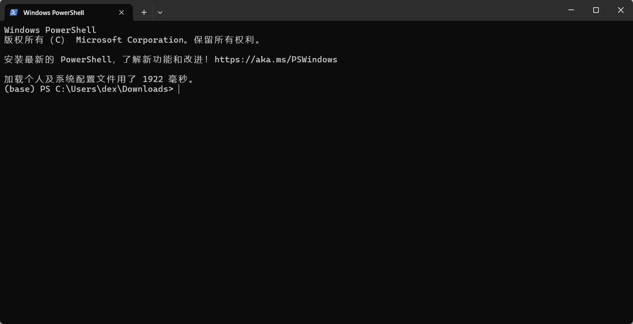
- In the download directory of the template generation script, right-click an empty area to open the "context menu", then click
Open in Terminalin the "context menu" to open theWindows PowerShellterminal, as shown below.
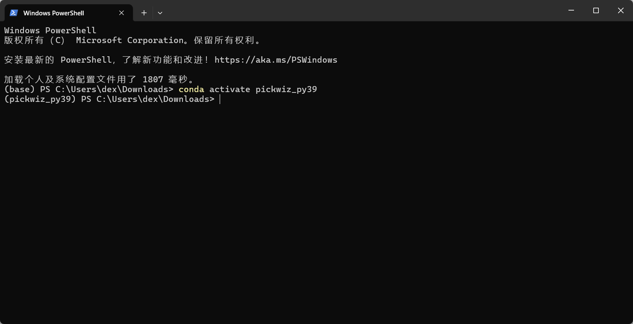
- Run the
conda activate pickwiz_py39command in the terminal to enter the pickwiz_py39 environment, as shown below.
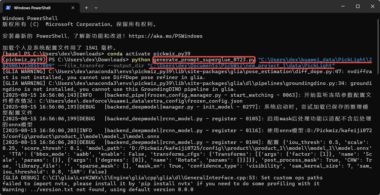
- After entering the pickwiz_py39 environment in the terminal, continue to execute the following command. You can modify it according to the template generation script name, the path of the historical data timestamp to copy, and the output save path.
python generate_prompt_superglue.py # Invoke the Python script; modify it according to the template generation script name
"C:\Users\dex\kuawei_data\PickLight\20240617150557809" # Path of the historical data timestamp to copy; modify it according to the actual timestamp
--file_transfer --output_dir # File transfer and output command
"C:\Users\dex\Documents\PickWiz\new_project_22\superglue" # Output file save path; you can change the save path as needed
Example: The PickWiz version is >=1.7.5, and the template generation script name is "generate_prompt_superglue.py";
The timestamp path of the historical data to copy is "D:\Pickwiz\new_project\data\PickLight\20250411144909289";
The output file save path is "C:\Users\dex\Documents\PickWiz\new_project_1\data\PickLight".
python generate_prompt_superglue.py # Invoke the Python script "generate_prompt_superglue.py"
"D:\Pickwiz\new_project\data\PickLight\20250411144909289" # Path of the historical data timestamp to copy
--file_transfer --output_dir # File transfer and output command
"C:\Users\dex\Documents\PickWiz\new_project_1\data\PickLight" # Output file save path
When running the command, modify the script name, historical data timestamp path, and output file save path, as shown below.
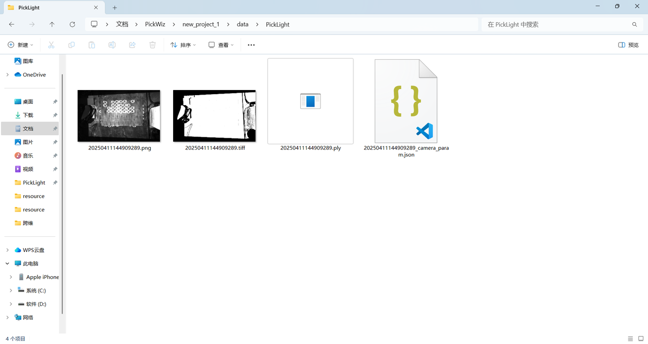
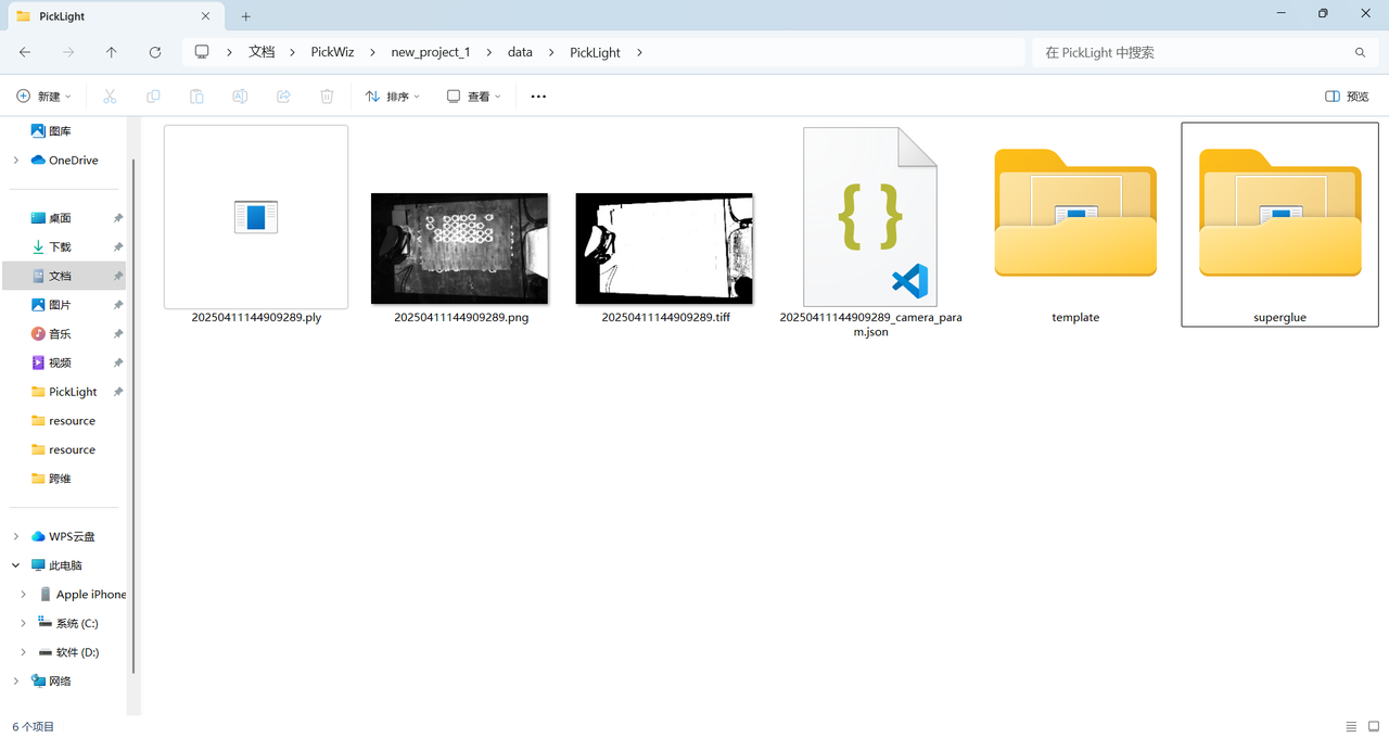
(4) After the command finishes, four files are generated under the save path: the scene's 2D image, depth image, scene Point Cloud, and Camera intrinsics
- Crop the Point Cloud
Open the scene Point Cloud .ply file in meshlab, crop away noise from the scene Point Cloud until only the target object's Point Cloud remains, and then click overwrite to save it directly.
When cropping the Point Cloud, carefully retain the complete Point Cloud of the target object.
| Before cropping | After cropping | Overwrite and save |
|---|---|---|
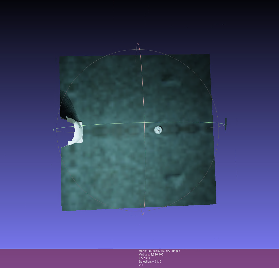 | 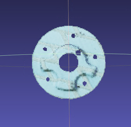 |  |
Generate the Point Cloud template
Run the
conda activate pickwiz_py39command in the terminal to enter the pickwiz_py39 environment.

- In the pickwiz_py39 environment, run the following command. You can modify it according to target object characteristics.
The script provides the --use_edge and --multi_temp parameters to adjust the template generation method. --use_edge indicates edge detection is used, and --multi_temp indicates multi-direction templates are generated for scenarios where the incoming material direction is not fixed. By default, neither parameter is added, which means multi-template mode and edge detection are disabled and the Point Cloud template is generated using the 2D image.
When the surface texture of the target object is not obvious, add the --use_edge parameter to enable edge detection, strengthen image features, and generate an edge-enhanced Point Cloud template.
python generate_prompt_superglue.py  # Invoke the Python script
"C:\Users\dex\Documents\lixin\unify_infer\superglue_model_gen\superglue" # Enter the save path from step 3 above
Example: When lighting conditions in the actual scene are unstable, or the target object surface texture is not obvious and the geometry is complex, you can add the --use_edge parameter. The script first performs edge detection on the 2D image and uses the result instead of the original 2D image for matching. During matching, it focuses on the geometric edge features of the target object and generates a Point Cloud template.
python generate_prompt_superglue.py # Invoke the Python script
"C:\Users\dex\Documents\PickWiz\new_project_1\data\PickLight" --use_edge # Enter the save path from step 3 above and add the --use_edge edge detection parameter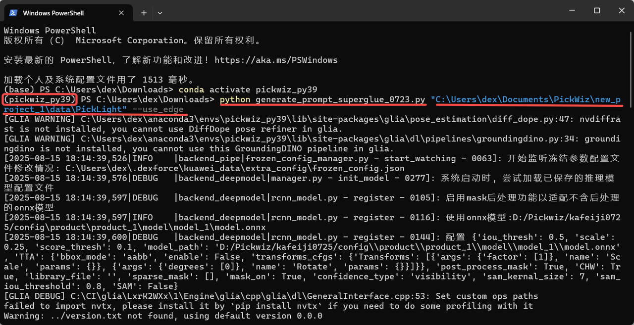
- After executing the command, a template folder named "superglue" is generated under the save path.
Check whether the following four files exist in this folder.
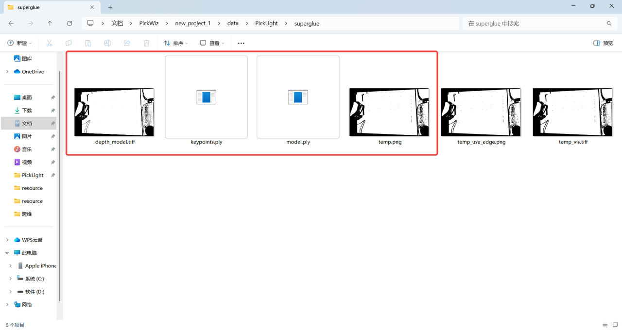
(Note: in grayscale mode, the template image is a grayscale image; in edge mode, it is a binary image.)
| Grayscale mode | 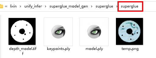 |
|---|---|
| Edge mode | 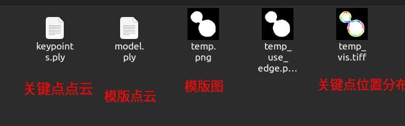 |
- If the incoming material includes multiple directions, an example of enabling multi-template mode is shown below. The
--angleargument specifies the rotation angles relative to the main template. After running the command, templates rotated by several angles based on the main template will be generated, as shown below.
python generate_prompt_superglue.py superglue-compressor --use_edge --multi_temp --angle 45 90 180 225 270As shown below

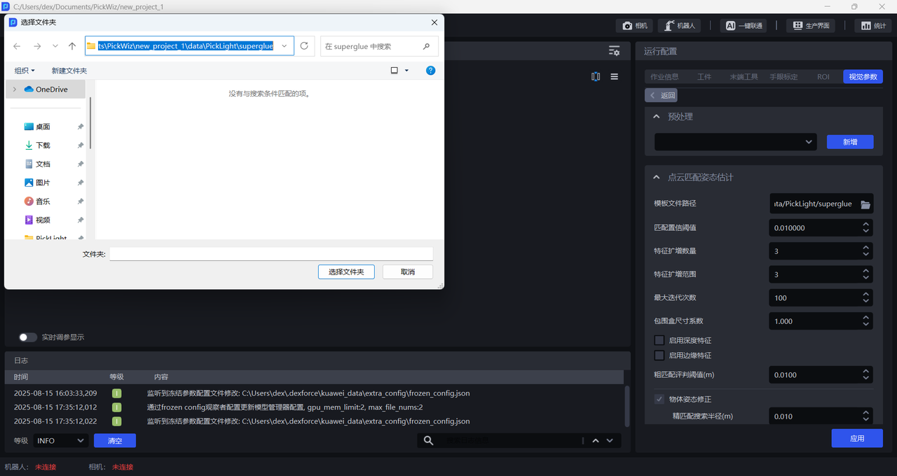
Import the Point Cloud template and select the template file path
Import the
model.plyfile in the "superglue" folder under the save path into thePoint Cloud filefield on the target object page as the Point Cloud template**.**
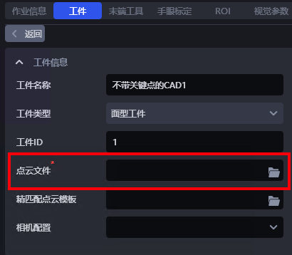
- In
Template file path, select the path of the "superglue" folder under the save path (for example, C:\Users\dex\Documents\PickWiz\new_project_1\data\PickLight\superglue).
- Template generation script parameter description
| Parameter name | Parameter description | Recommended value | Brief description |
|---|---|---|---|
| data_dir | Path of the prior-data folder | \ | Use the same file path as in the previous data-generation script. When copying a Windows path, a single backslash "\" may cause a path error. Replace single backslashes with double backslashes or use the forward slash "/" shown in the recommended value. |
| file_transfer | Whether to copy files | \ | \ |
| output_dir | Takes effect only when file_transfer is enabled | \ | \ |
| scale | Scaling factor for projecting the Point Cloud to generate a Mask | 0.1 | Scaling factor for projecting the Point Cloud to generate a Mask |
| use_edge | Whether to enable edge mode; if not enabled, grayscale mode is used | \ | When multiple layers are stacked, the model may have difficulty distinguishing the contours of lower-layer objects from upper-layer objects, so grayscale mode should be used |
| multi_temp | Whether to generate multi-direction templates | The default is false, which means only a single-direction template is generated by default | |
| mask_kernel_size | Kernel size for the closing operation when projecting the Point Cloud to a Mask | 5 | Use the default value |
| edge_kernel_size | Kernel size used during edge feature extraction | 3 | 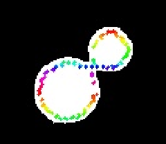 The larger the value, the more inward the feature map shifts The larger the value, the more inward the feature map shifts |
| angle | In multi-template mode, the rotation angle of the sub-template relative to the main template | \ | For the angle input format, refer to the example command |
2.2.2 Matching Confidence Threshold (mm)

- Function
The Confidence score for feature-point matching. The higher the score, the higher the quality of the feature points, but the number of matched feature points may be smaller.
- Use Case
Ordered loading and unloading scenario for planar target objects (parallelized)
- Parameter Description
Default value: 10
Value range: [10, 800]
2.2.3 Number of Feature Augmentations
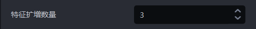
- Function
Artificially increase the number of feature points based on the original feature-point detection to prevent abnormal matching caused by too few feature points.
- Use Case
Ordered loading and unloading scenario for planar target objects (parallelized)
- Parameter Description
Default value: 3
Value range: [0, 99]
2.2.4 Feature Augmentation Range
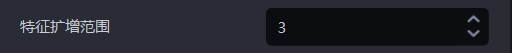
- Function
The neighborhood range used for feature-point augmentation
- Use Case
Ordered loading and unloading scenario for planar target objects (parallelized)
- Parameter Description
Default value: 3
Value range: [0, 99]
- Tuning
When the scene Point Cloud quality is good, this parameter can be increased appropriately; conversely, when the scene Point Cloud quality is poor, reduce this parameter.
2.2.7 Maximum Number of Iterations
- Function
Limit the maximum number of iterations during the coarse matching stage to avoid wasted computing resources caused by infinite loops or overly slow convergence.
- Use Case
Ordered loading and unloading scenario for planar target objects (parallelized)
- Parameter Description
Default value: 100
Modification is not recommended. This function will be hidden later.
2.2.8 Bounding Box Size Coefficient
- Function
Dynamically adjust the size of the bounding box to control the scaling ratio of the detected bounding box length and width.
- Use Case
Ordered loading and unloading scenario for planar target objects (parallelized)
- Parameter Description
Default value: 1.0
- Tuning
To reduce background interference or incorrect merging of adjacent targets, shrink the detection range with a coefficient <1.0;
To prevent parts of the target (such as occluded regions) from being cropped, enlarge the detection range with a coefficient >1.0;
Adjust this coefficient according to the bounding box results in 2D Recognition
2.2.9 Enable Depth Features

- Function
Use features extracted by the SuperGlue model instead of traditional Point Cloud features to resolve matching abnormalities in complex scenes.
- Use Case
Ordered loading and unloading scenario for planar target objects (parallelized)
- Tuning
Suitable for target objects with smooth surfaces, repeated textures, or large lighting changes, and for mixed loading and unloading of multiple target object categories
2.2.10 Enable Edge Features

- Function
When enabled, feature points are extracted and matched only in the edge regions of the object
- Use Case
Ordered loading and unloading scenario for planar target objects (parallelized)
- Parameter Description
The object's edge regions (such as contours and sharp transition regions) are used, while flat or texture-uniform regions are ignored.
When creating the template, use_edge must also be enabled to ensure feature consistency.
2.2.11 Coarse Matching Evaluation Threshold (mm)

- Function
During coarse matching of feature points, retain only matched points whose Confidence is higher than this value.
- Use Case
Ordered loading and unloading scenario for planar target objects (parallelized)
- Parameter Description
Default value: 10
Value range: [0.1, 1000]
- Tuning
Low threshold (such as 5): reduces mismatches, but may lose valid points.
High threshold (such as 20): retains more matches, but increases noise.
2.2.12 Target Object Pose Correction
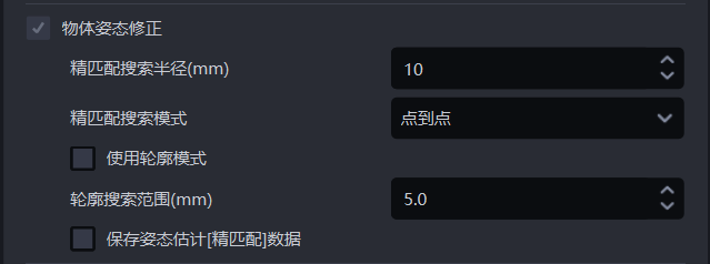
Fine Matching Search Radius (mm)

- Function
During fine matching, the template Point Cloud is matched with the instance Point Cloud, and each point in the template Point Cloud needs to search for its nearest point in the instance Point Cloud. The fine matching search radius represents both the search radius in the instance Point Cloud and the distance threshold between each point in the template Point Cloud and its nearest point in the instance Point Cloud. If the distance between a point and its nearest point is smaller than the fine matching search radius, the two points are considered matchable; otherwise, they are considered not matchable.
- Use Case
Ordered loading and unloading of planar target objects, random picking of planar target objects, and planar target object positioning and assembly scenarios
- Parameter Description
Default value: 10
Value range: [1, 500]
Unit: mm
- Tuning
Usually left unchanged
Fine Matching Search Mode

- Function
The method used by the template Point Cloud to search for the nearest points in the instance Point Cloud during fine matching
- Use Case
Adjust this function when the fine matching result between the template Point Cloud and the instance Point Cloud is poor
- Parameter Description
| Parameter | Description |
|---|---|
| Point to point | Each point in the template Point Cloud searches for the nearest point in the instance Point Cloud (the point with the shortest straight-line distance within the search radius). Suitable for all target objects. |
| Point to plane | Each point in the template Point Cloud searches for the nearest point in the instance Point Cloud along its normal vector. Suitable for target objects with obvious geometric features. |
| Combination of point-to-point and point-to-plane | First use point-to-point mode to optimize the target object's pose in the instance Point Cloud, then use point-to-plane mode to optimize the target object's pose in the instance Point Cloud. Suitable for target objects with obvious geometric features.
|
Use Contour Mode

- Function
Extract contour Point Clouds from the template Point Cloud and the instance Point Cloud for coarse matching
- Use Case
In ordered loading and unloading of planar target objects, random picking of planar target objects, and planar target object positioning and assembly scenarios, if the coarse matching result using keypoints is poor, select this function to perform coarse matching again using contour Point Clouds.
- Tuning
The coarse matching result affects the fine matching result. If the fine matching result is poor, select Use Contour Mode
Contour Search Range (mm)

- Function
The search radius for extracting contour Point Clouds from the template Point Cloud and the instance Point Cloud
- Use Case
General target object ordered loading and unloading, general target object random picking, and general target object positioning and assembly scenarios
- Parameter Description
Default value: 5
Value range: [0.1, 500]
Unit: mm
- Tuning
When the value is smaller, the radius for searching contour Point Clouds is smaller, which is suitable for extracting fine target object contours, but the extracted contours may contain outlier noise;
When the value is larger, the radius for searching contour Point Clouds is larger, which is suitable for extracting broader target object contours, but the extracted contours may ignore some detailed features.
Save Pose Estimation [Fine Matching] Data
- Function
When selected, fine matching data is saved
- Use Case
Ordered loading and unloading of planar target objects, random picking of planar target objects, planar target object positioning and assembly, and planar target object positioning and assembly (matching only)
- Example
Fine matching data is saved in the \project folder\data\PickLight\historical data timestamp\Builder\pose\output folder under the project save path.
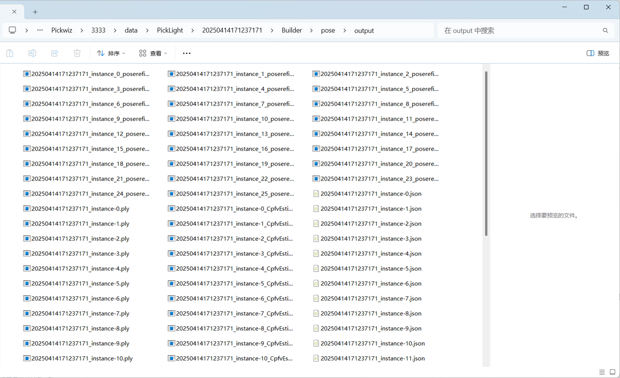
2.3 Empty ROI Check
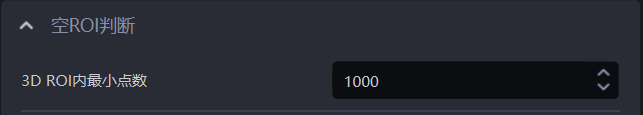
- Function
Determine whether there are still target objects (Point Clouds) remaining in ROI 3D. If the number of 3D points in ROI 3D is smaller than this value, it indicates that no target object Point Cloud remains, and no Point Cloud is returned.
- Parameter Description
Default value: 1000
Value range: [0, 100000]
- Usage Procedure
Set the minimum point-count threshold for ROI 3D. If the count is smaller than this threshold, the target object Point Cloud in ROI 3D is insufficient, so it is determined that no target object remains in ROI 3D;
In Robot configuration, add a new vision status code to facilitate subsequent robot signal processing.