ModBus Communication Configuration
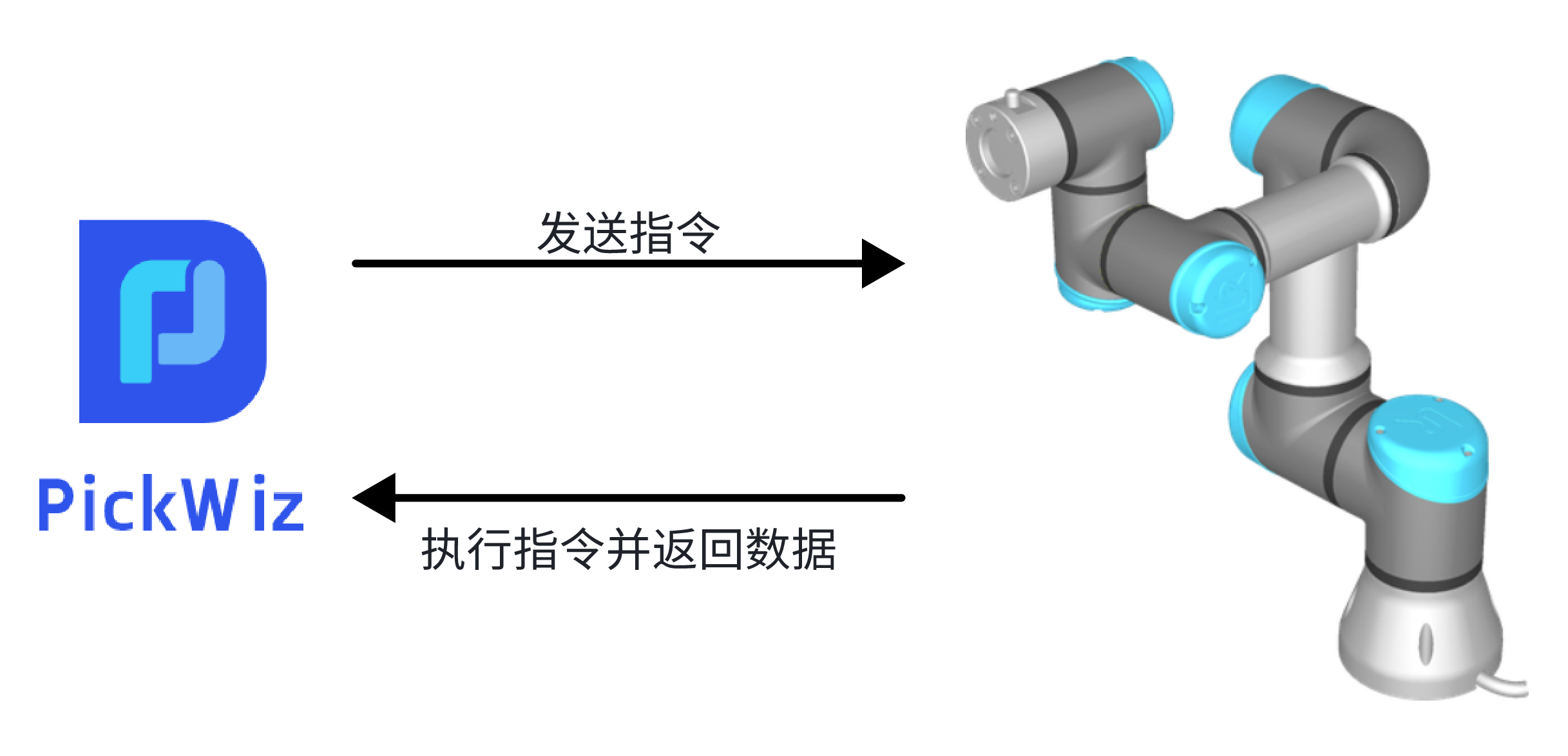
ModBus is a communication method in which PickWiz acts as the client and the robot acts as the server. When PickWiz communicates with the robot, it actively controls the robot, sends commands to the robot, and the robot executes the commands and returns data after receiving them.
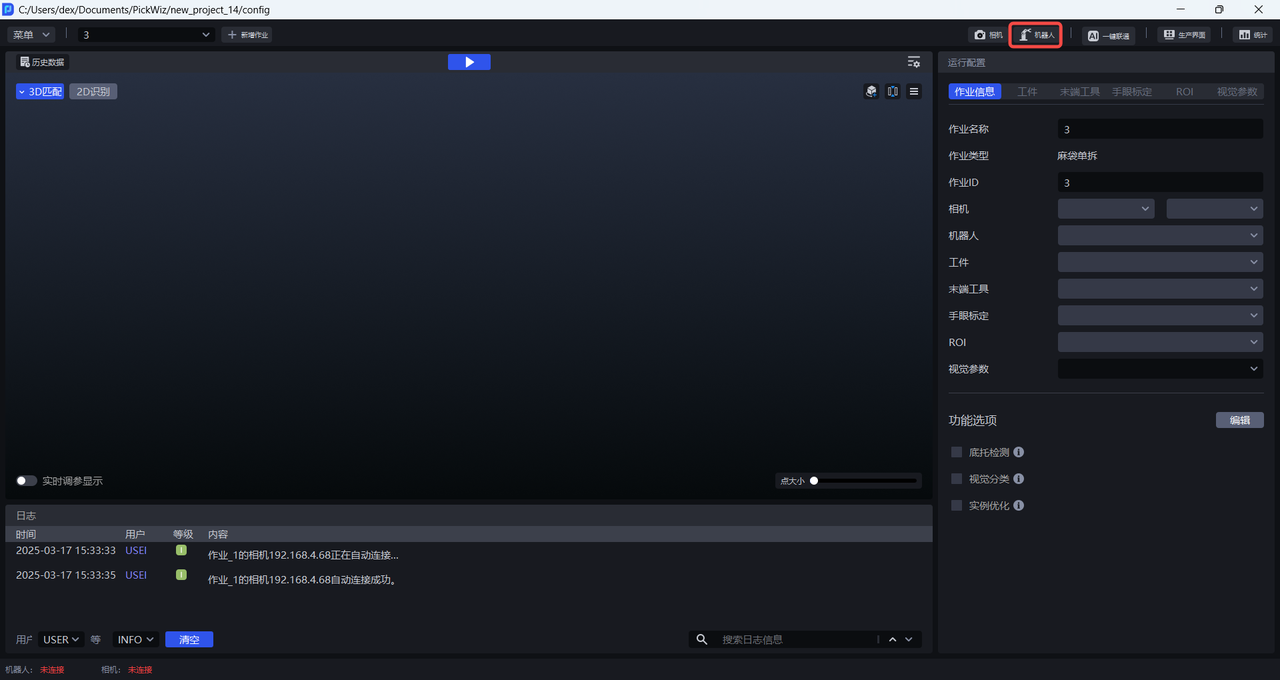
Before configuring ModBus communication for the robot, please first refer to Project Operation Guide to create a new Project, then click Robot Configuration Panel on the main interface to enter the Add Robot interface.
1. Add Robot
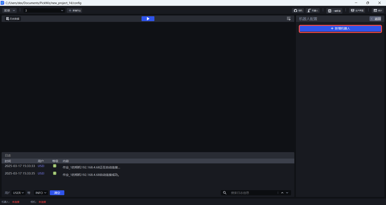
(1)Enter the Add Robot interface and click +Add Robot
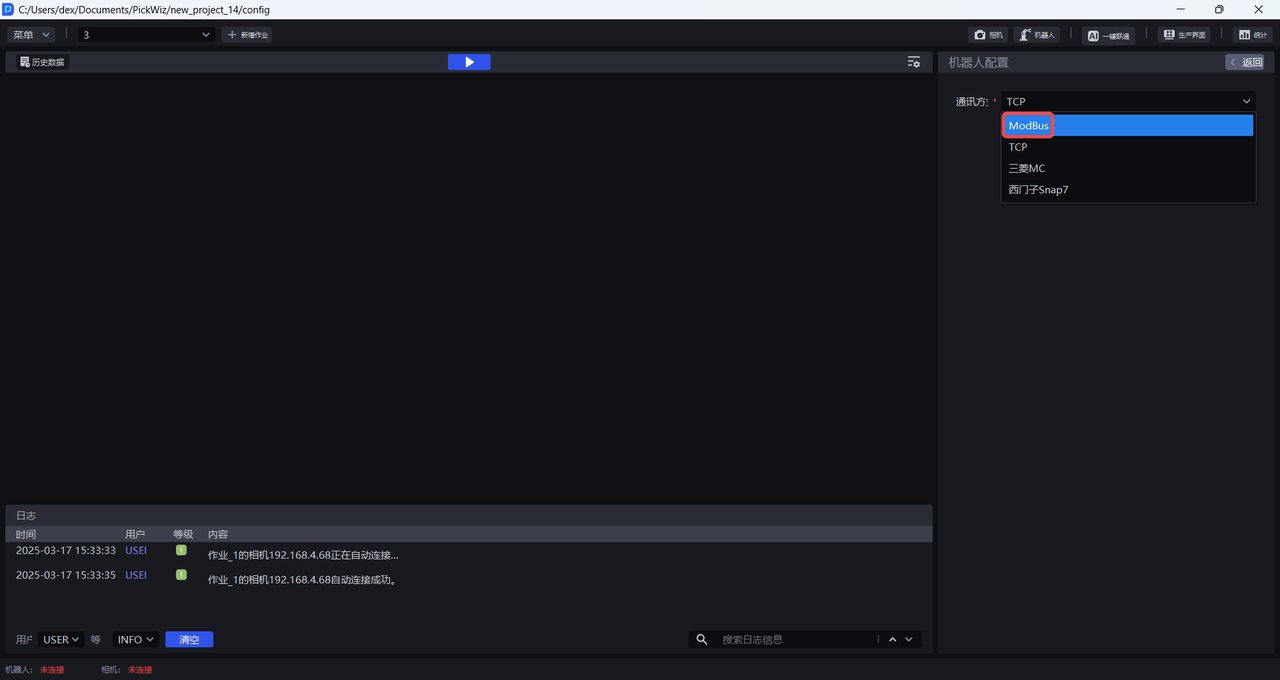
(2)Select ModBus as the communication method, click Next, and enter the Robot Configuration interface
2. Configure the Robot
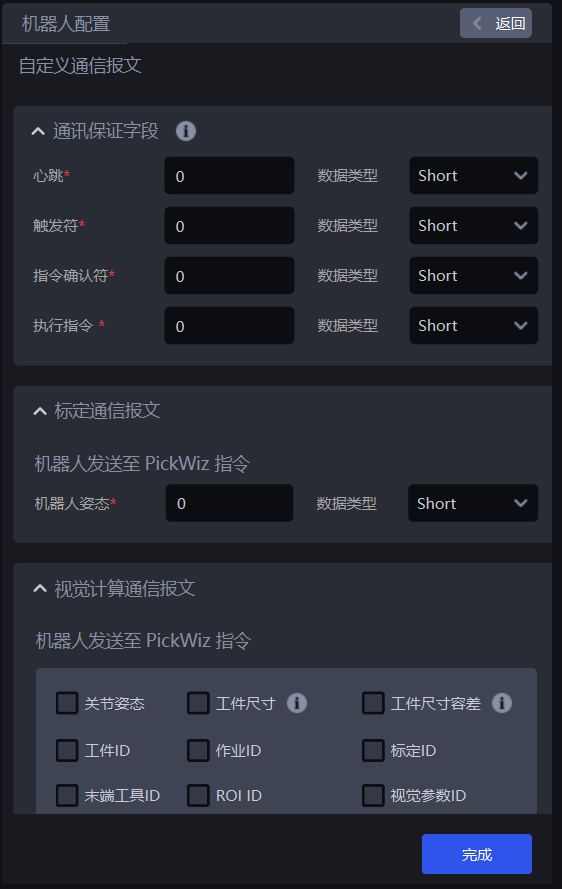
On the Robot Configuration interface, you can configure robot information, basic communication settings, and custom communication messages.
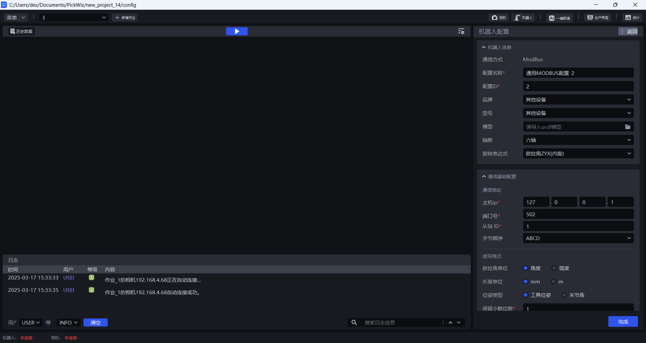
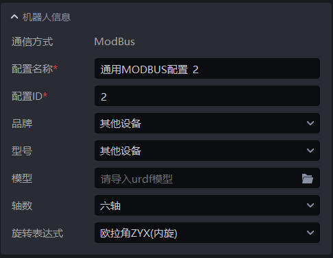
2.1 Robot Information Configuration
| Configuration Item | Description |
|---|---|
| Communication Method | The communication protocol established between PickWiz and the robot. This cannot be modified |
| Configuration Name | The name of the robot configuration. Chinese and English characters, numbers, and symbols are supported |
| Configuration ID | The unique identifier of the robot configuration. It can be modified and supports numbers only |
| Brand | The robot brand. If the robot side is connected to a PLC, select Other Device for the brand |
| Model | The robot model. If the robot side is connected to a PLC, select Other Device for the model |
| Model File | When Other Device is selected for brand and model, you need to upload the model of that device. The model file format is urdf |
| Axis Count | The number of robotic arm axes. Three-axis, four-axis, and six-axis are supported |
| Rotation Expression | Describes the robot pose in three-dimensional space. Currently, Euler Angles and rotation vector are supported, and the Euler angle order can be modified. |
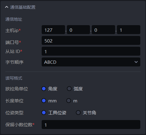
2.2 Basic Communication Configuration
| Configuration Item | Description | |
|---|---|---|
| Communication Address | Host IP | The host IP address. In ModBus communication mode, the default is 127.0.0.1 |
| Port Number | The specified port on the host to which the robot connects. The default port is 502 and usually does not need to be modified | |
| Slave ID | The unique identifier of the robot. Through the slave ID, PickWiz can accurately identify and distinguish each robot. Numbers only are supported. The default is 1 and can be modified | |
| Byte Order | The byte order used when PickWiz communicates with the robot in ModBus mode. Options are ABCD/BADC/CDAB/DCBA, with ABCD as the default | |
| Read/Write Format | Euler Angle Unit | The unit of Euler Angles. Degree and radian are supported, with degree as the default. |
| Length Unit | The length unit used by the robot, including Robot Pose, workpiece dimensions, etc. The default is mm | |
| Pose Type | The representation of Robot Pose. The default is Tool Pose. Tool Pose refers to the pose of the robot end Tool; Joint Motion refers to the pose of each robot joint, and the combination of all joint poses determines the pose of the robotic arm or end Tool. When Other Device is selected for the robot brand and model, only Tool Pose can be selected as the default pose type | |
| Reserved Decimal Places | How many decimal places to retain for floating-point data in robot commands. Numbers only are supported, and the default is 1 | |
2.3 Custom Communication Message Configuration
3. ModBus Command Description
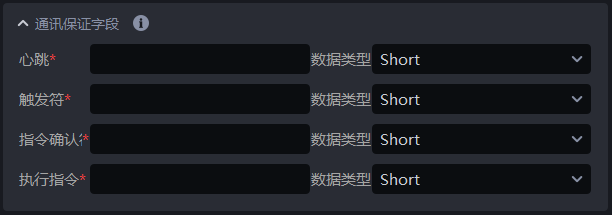
3.1 Communication Assurance Fields
The communication assurance fields are used to monitor the communication status and ensure the uniqueness and correctness of command execution.
| Field | Description |
|---|---|
| Heartbeat | Used to monitor the communication status. When the robot/PLC is connected to PickWiz, PickWiz writes 1 to the corresponding address block; when the robot/PLC is disconnected from PickWiz (PickWiz has not written 1 for a long time), the robot/PLC writes 0 to that address block |
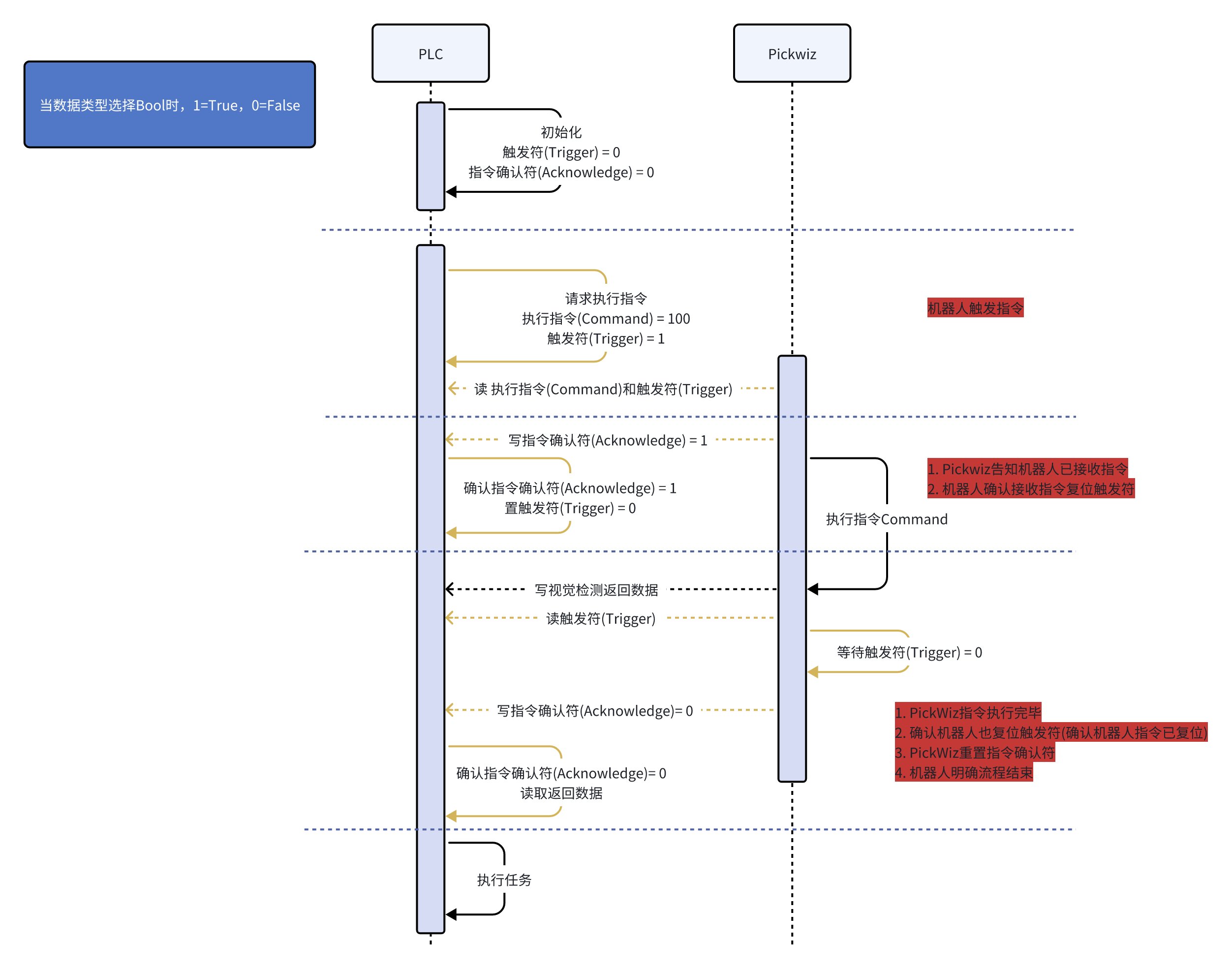
| Trigger Flag | Used to indicate whether the robot/PLC has triggered a command. When the robot/PLC triggers a command, it writes 1 to the trigger flag address block, and PickWiz reads data from the trigger flag address block. After the robot/PLC receives confirmation that PickWiz has received the command (the command acknowledgment flag is 1), the robot/PLC writes 0 to the trigger flag address block to prevent the robot/PLC from triggering again. After PickWiz executes the command, PickWiz returns the vision inspection result to the robot/PLC and simultaneously reads data from the trigger flag address block. If 0 is read, the robot/PLC can read the returned vision inspection result |
| Command Acknowledgment Flag | Used to indicate whether PickWiz has received the command. After the robot/PLC triggers a command and PickWiz reads it, PickWiz writes 1 to the command acknowledgment flag address block to notify the robot/PLC that the command has been received. After PickWiz finishes executing the command and confirms that the robot/PLC has reset the trigger flag (written 0), PickWiz synchronously resets the command acknowledgment flag (writes 0), informing the robot/PLC that the command has been executed and the process is complete. The robot then reads the returned vision inspection result and executes the task. |
| Execution Command | Used to indicate that the robot/PLC executes a command. When the robot/PLC needs to execute a command, it writes 100/101 to the execution command address block. PickWiz reads data from the execution command address block to determine which command the robot/PLC needs to execute. 100 is the photo-taking command, and 101 is the clear-cache command (used in `one shot, multiple picks` mode) |
3.2 Calibration Communication Messages
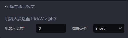
Commands Sent from the Robot to PickWiz
Used for eye-hand calibration and for obtaining the current real-time Robot Pose in PickWiz when eye in hand triggers image capture.
If Pose Type in the basic communication configuration is set to Tool Pose, send the current Robot Pose of the robot end Tool to PickWiz (6 data values);
If Pose Type in the basic communication configuration is set to Joint Motion, send the joint pose (6 data values), which is used to calculate the Pick Point joint pose closest to the reference joint pose.
During eye-hand calibration or when
eye in handtriggers image capture, the robot writes the current real-time Robot Pose to this address block, and PickWiz reads the pose from this address block.The Robot Pose consists of 6 data values, so storage space for 6 data values must be reserved when writing to the address block.
3.3 Vision Computation Communication Messages
When the Execution Command value is 100, vision computation can be performed and the following messages take effect. After the checkbox is selected, the corresponding address input box appears below. Enter the address block, and when the robot triggers the photo-taking command, it writes data to the corresponding address block, which PickWiz reads.
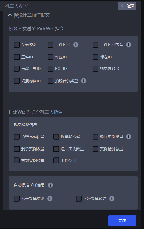
(1)Commands Sent from the Robot to PickWiz
| Field | Description |
|---|---|
| Joint Pose | The robot reference joint pose. For 6 data values, when Pose Type is Joint Motion, Reference Joint Pose must be entered to calculate the Pick Point joint pose closest to the reference joint pose |
| Workpiece Dimensions | The incoming workpieces may have multiple sizes, so the robot needs to automatically adjust the grasping strategy based on different sizes. In different scenarios, the number of workpiece dimension values passed from the robot side and the corresponding workpiece information differ. For the circular surface scenario, 1 value is passed, representing the radius; for the cylinder scenario, 2 values are passed, representing radius\height; for the carton scenario, 3 values are passed, representing length\width\height; for the quadrilateral scenario, 2 values are passed, representing width\length. |
| Workpiece Dimension Tolerance | The incoming workpieces may have multiple sizes, so the robot needs to automatically adjust the grasping strategy based on different sizes. In different scenarios, the number of workpiece dimension tolerance values passed from the robot side and the corresponding workpiece information differ. For the circular surface scenario, 1 value is passed, representing the radius tolerance; for the cylinder scenario, 2 values are passed, representing radius\height tolerances; for the quadrilateral scenario, 2 values are passed, representing width\length tolerances. |
| Workpiece ID | Workpiece ID, used by the robot to automatically switch the workpiece to pick |
| task ID | task ID, used by the robot to automatically switch tasks |
| Calibration ID | Calibration ID, used by the robot to automatically switch eye-hand calibration configuration files |
| Tool ID | Tool ID, used by the robot to automatically switch the end Tool during task execution |
| ROI ID | The ID of the ROI, used by the robot to automatically switch the ROI |
| Vision Parameter ID | Vision Parameter ID, used by the robot to automatically switch vision parameters |
| Scene Object ID | Scene Object ID, used by the robot to automatically switch the Scene Object |
| Photo Computation Type | Photo computation type 0: retake a photo, acquire an image, and then perform vision computation; 1: use the cached image (the last acquired image) for vision computation; 2: only take a photo and acquire the image 3: take a photo for random pose automatic sampling 4: real-time correction of vision drift 5: use historical data for vision computation 6: IPC shutdown |
(2)Commands Sent from PickWiz to the Robot
- Vision Inspection Information
| Field | Description |
|---|---|
| Photo Completion Signal | Photo completion signal, 1 value, indicating that photo-taking is complete and reset is required after the robot/PLC receives it |
| Inspection Result Signal | Vision inspection signal, 1 value. The default success value is 100, and other exceptions are 0. Custom configuration is supported |
| Returned Instance Type | Returned instance type, 1 value. An instance type value of 0 indicates a workpiece, and 1 indicates a pallet. The picking-related information differs for different instance types |
| Remaining Instance Count | Remaining instance count, 1 value. In the one shot, multiple picks picking logic, this returns the current remaining cached instance count |
| Returned Instance Count | Returned instance count, 1 value. Returns the number of instances identified by instance segmentation 2D recognition. This value is less than or equal to the Sent Instance Count. If there are multiple instances, the Grasp-related Information Length increases with the returned instance count |
| Total Detected Instances | Total detected instances, 1 value. The number of detected instances before instance filtering |
| Valid Instance Count | Valid instance count, 1 value. The number of detected instances after instance filtering |
| Workpiece Type | The type ID that can be returned when recognizing multiple workpiece types. |
- Automatic Calibration Sampling Send Command
When the eye-hand calibration method is
random pose automatic sampling, this command must be configured. Otherwise, the robot cannot communicate with PickWiz
| Field | Description |
|---|---|
| Calibration Sampling Result: Different calibration sampling results correspond to different signal values | 0: the sample count reaches the minimum quantity 1: successfully added a new sample 11: failed to add a new sample 12: automatic sampling ended and the sample list has been executed 13: failed to generate a sampling pose 14: calibration sampling page was not opened 15: system error |
| Next Sampling Pose | The moving position for the robot to collect the next calibration sample |
- Grasp-related Information
The lengths of the grasp-related information described below are for a single Pick Point. If there are multiple Pick Points, the length is the number of values x the number of Pick Points
Universal information for all scenarios
| Field | Description |
|---|---|
| Workpiece Category | / |
| Picked Workpiece ID | 1 value; indicates the current workpiece sequence number |
| Pick Point Pose | 6 values; indicates the pose data of the Pick Point |
| Pick Point Index | 1 value; indicates the current Pick Point sequence number |
| Additional Information | 1 value; indicates the custom additional information of the current workpiece |
| Forward Point | Only applicable when the pose type is Joint Motion. The length is 1 + the number of Waypoints; the format is (number of Waypoints, joint Waypoint poses from the pre-pick point to the Pick Point) |
| Retreat Point | Only applicable when the pose type is Joint Motion. The length is 1 + the number of Waypoints; the format is (number of Waypoints, joint Waypoint poses from the Pick Point to the retreat pick point) |
- Vision Status Code
The vision status codes are used for troubleshooting. The complete status codes are shown in the table below
In Commands Sent from PickWiz to the Robot - Vision Inspection Information, select
Vision Status Codeand configure the address block and communication data type.If the vision status code is not custom-configured, the default value is
100for success and0for all other exceptions
| Error Content | Default Value | Related Node |
|---|---|---|
| Success | 100 | / |
| Bottom plate detected | 301 | Foreground Processing(Foreground Builder) |
| No container detected | 4000 | Container Detection(Container Builder) |
| No instance detected | 5000 | Instance Segmentation(Instance Builder) |
| No pose detected | 6000 | Pose Estimation(Pose Builder) |
| No Pick Point detected | 7000 | Pick Point Generation(Grasp Builder) |
| No Path detected | 8000 | Robot Trajectory Generator(Trajectory Builder) |
| No instance dimensions detected | 9000 | Workpiece Dimensions Generator(Size Builder) |
| Empty ROI | 1101 | Invalid Point Filter(ValidPoints Criteria) |
| No valid instance | 12000 | Instance Filtering(Instance Criteria) |
| No valid workpiece pose | 13000 | Pose Filtering(Pose Criteria) |
| No valid Pick Point | 14000 | Pick Point Filtering(Grasp Criteria) |
| All detection results are unpickable due to collisions | 15000 | Collision Detection Filtering(Collision Criteria) |
| No instance with valid dimensions | 17000 | Workpiece Dimensions Filtering(Size Criteria) |
| Exception | 20000 | General exception error. Please check the logs for confirmation |
| Insufficient video memory | 20001 | General exception error. Please check the logs for confirmation |
| Invalid input (please check algorithm parameters) | 20002 | General exception error. Please check the logs for confirmation |
| Full inspection | 20003 | Related to point cloud processing operator(full_detect_judgment) |
| Foreign matter detection exception | 20004 | Related to instance filtering operator(foreign_matter_judgement) |
4. Edit, Copy, and Delete Robot Configurations
(1)Edit Robot Configuration
On the Add Robot interface, left-click a robot configuration to edit the selected robot configuration.
(2)Copy Robot Configuration
On the Add Robot interface, right-click a robot configuration to copy the selected robot configuration.
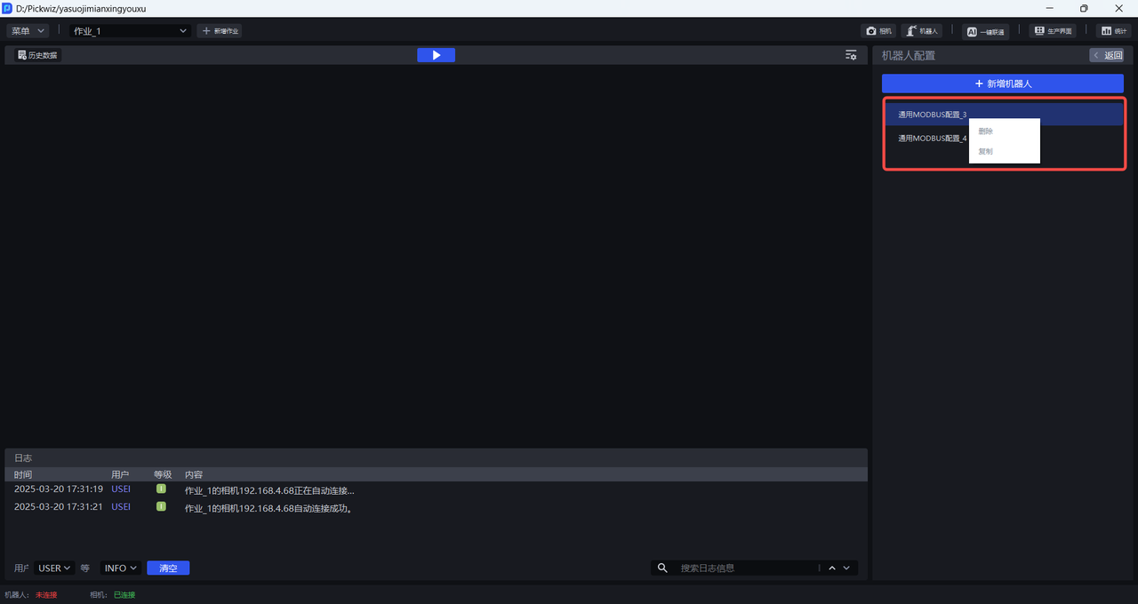
(3)Delete Robot Configuration
On the Add Robot interface, right-click a robot configuration to delete the selected robot configuration.

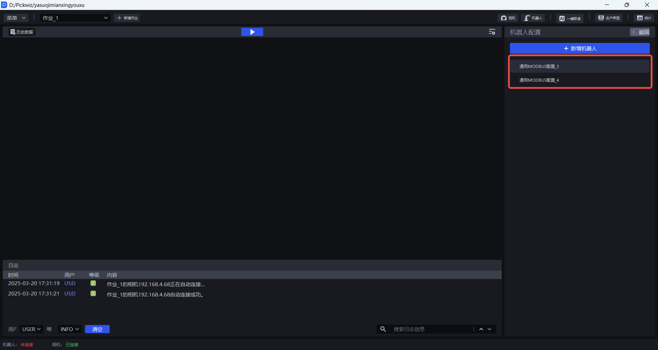
5. Select a Robot Configuration
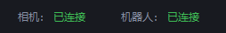
After completing the ModBus communication configuration, you can select a robot configuration for the current task scenario on the task main interface. Select the corresponding robot configuration in the robot configuration selection bar, and PickWiz will attempt to establish communication with the robot through the ModBus communication protocol.
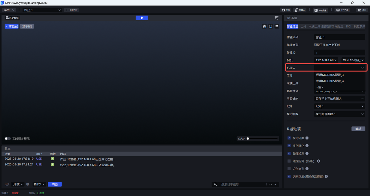
If the communication connection is successful, the robot communication connection status in the lower-left corner of the main interface will display "Connected".
If the communication connection fails, the robot communication connection status will display "Disconnected". Please check whether the network cable between the robot and the industrial PC is securely connected and whether the program loaded and running on the robot system is correct, then reconfigure the robot.