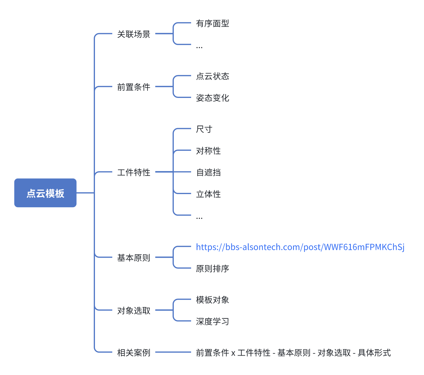
Elements, Principles, and Examples of Point Cloud Template Creation
Mind Map
Content
Instructions for Creating Workpiece Point Cloud Templates
I. Preconditions
| Precondition | Definition | Notes |
|---|---|---|
| Workpiece Pose Variation | Finite poses (countable): only fixed surfaces of the workpiece can be seen (such as the front side), and the valid Point Cloud region is the area on that surface that remains stably visible. Arbitrary poses: the workpiece may appear at any angle, and the valid Point Cloud region is the area that can be stably imaged in more than 80% of poses (excluding portions where Point Cloud is easily missing, such as deep holes, overexposed areas, grooves, etc.). | Ordered scenes: The template should rely only on the Point Cloud of fixed visible surfaces to avoid matching failure caused by invisible surfaces. Unordered scenes: Stable visible regions must be determined through multi-view scanning or CAD simulation. Exclude regions where Point Cloud is easily missing (such as reflective surfaces and deep concave structures) to avoid relying on unreliable Point Cloud. Confirmation method: Capture Point Cloud under different poses, count the visibility frequency of each region, and screen out the valid Point Cloud regions. |
| Camera Point Cloud Imaging Quality | The quality and completeness of the Point Cloud data obtained after recognizing the target workpiece with a 3D camera (such as structured light, stereo vision, etc.). | Point Cloud Missing Common causes: Workpiece properties (high reflectivity or translucent materials prevent laser return). Ambient light interference (strong illumination causes sensor saturation). View occlusion (self-occlusion of the workpiece or occlusion by external objects). Optimization strategies: Adjust lighting: use diffuse light or polarized filtering to reduce reflective interference. Local template: use Point Cloud from visible regions with better quality as the template. Discontinuous Point Cloud depth and high noise Common causes: Workpiece properties (multi-layer structures, transparent/semi-transparent materials). Camera exceeds the disparity range (Point Cloud distortion caused by measurement distance being too close/far). Occlusion from stacked objects (for example, stacked workpieces causing mixed Point Cloud). Optimization strategies: Filtering and denoising: use filtering and outlier removal functions to optimize Point Cloud quality. Depth calibration: ensure that the camera acquires data within the optimal working distance. Layered analysis: extract Point Cloud by regions for stacked workpieces to avoid mismatching. |
II. Workpiece characteristics
| Attribute (higher priority means higher importance) | Definition | Notes |
|---|---|---|
| Size | The physical size of the workpiece (volume, area) affects the Point Cloud acquisition density and the computational complexity of the template. |
|
| Self-occlusion | The structure of the workpiece itself causes some regions to fail to form Point Cloud under certain views (such as multi-layer nesting, stacked workpieces, complex curved surfaces, etc.). |
|
| Three-dimensionality | The degree of depth variation of the workpiece in 3D space (such as height differences, stepped structures, curved-surface undulations, etc.). |
|
| Symmetric | The workpiece has a symmetric structure (such as bilateral symmetry or rotational symmetry). |
|
| Concave | The surface of the workpiece has recessed structures (such as inner holes and grooves), which may cause Point Cloud missing or unstable imaging. |
|
| Convex | The surface of the workpiece has convex curved structures, which may lead to unstable Point Cloud imaging. |
|
| Planar | The surface of the workpiece is approximately planar and lacks obvious internal features. |
|
| Dynamic update status | / |
|
III. Basic principles
| When using modeling for matching in industrial robot 3D vision, feature selection should follow the following principles | |
|---|---|
| Characteristic | Description |
| Saliency | Select features that are prominent and easy to recognize on the object surface, such as edges, corners, textures, and concave/convex surfaces. These features should have strong distinguishability so that they can be quickly detected and matched in the scene. |
| Stability | Features should maintain a certain degree of stability against changes in lighting and viewpoint. Even if the object is rotated, scaled, or deformed, these features should remain relatively unchanged |
| Uniqueness | Features should be sufficiently distinctive and not easily confused with features of other objects or the environment. This helps improve the accuracy and reliability of matching. |
| Density | Distribute feature points as densely as possible on the object surface to increase matching redundancy. In this way, even if some feature points are occluded or lost, matching can still be completed by relying on other feature points. |
| Repeatability | Select features that can be stably detected under different viewpoints and lighting conditions. This ensures that the features can be accurately recognized in various scenarios. |
| Computational efficiency | The extraction and description process of features should be as efficient as possible to meet the real-time response requirements of industrial robots. Some features with relatively low computational cost can be selected. |
IV. Notes for targeted scenarios
The general considerations for Point Cloud Template creation under different industrial scenarios and technical-path backgrounds are as follows
| Scenario | Scene Image | Point Cloud Image
| Template
| Point Cloud Template notes: Preconditions x Workpiece Characteristics - Basic Principles - Object Selection - Specific Form | Mitigation plan for notes |
|---|---|---|---|---|---|
| Generic Ordered | 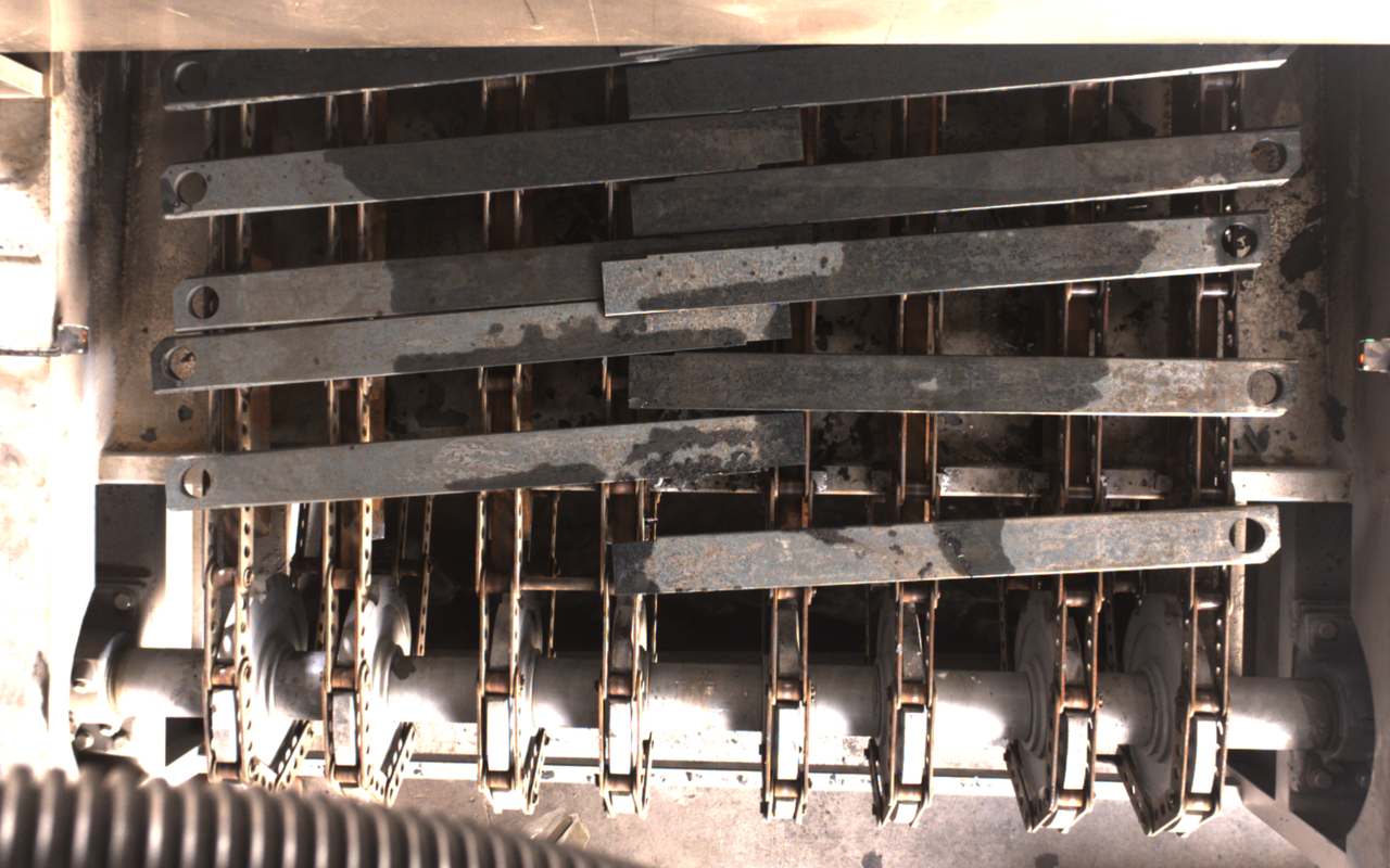 | 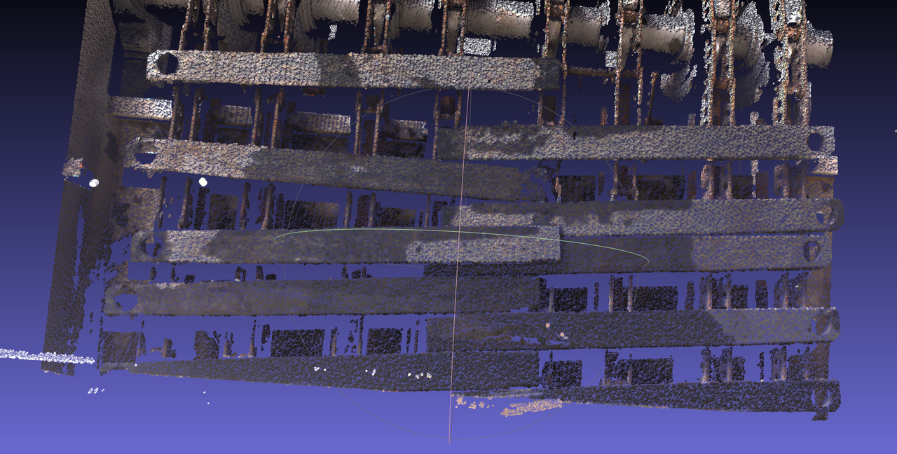 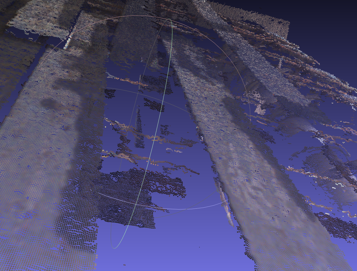 | 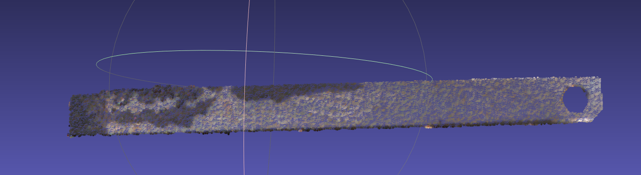 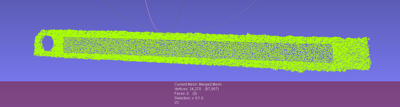 | Preconditions: Workpiece characteristics: large elongated part (may deform), planar workpiece. Basic principles: | Preconditions: Workpiece characteristics: |
| Generic Unordered | 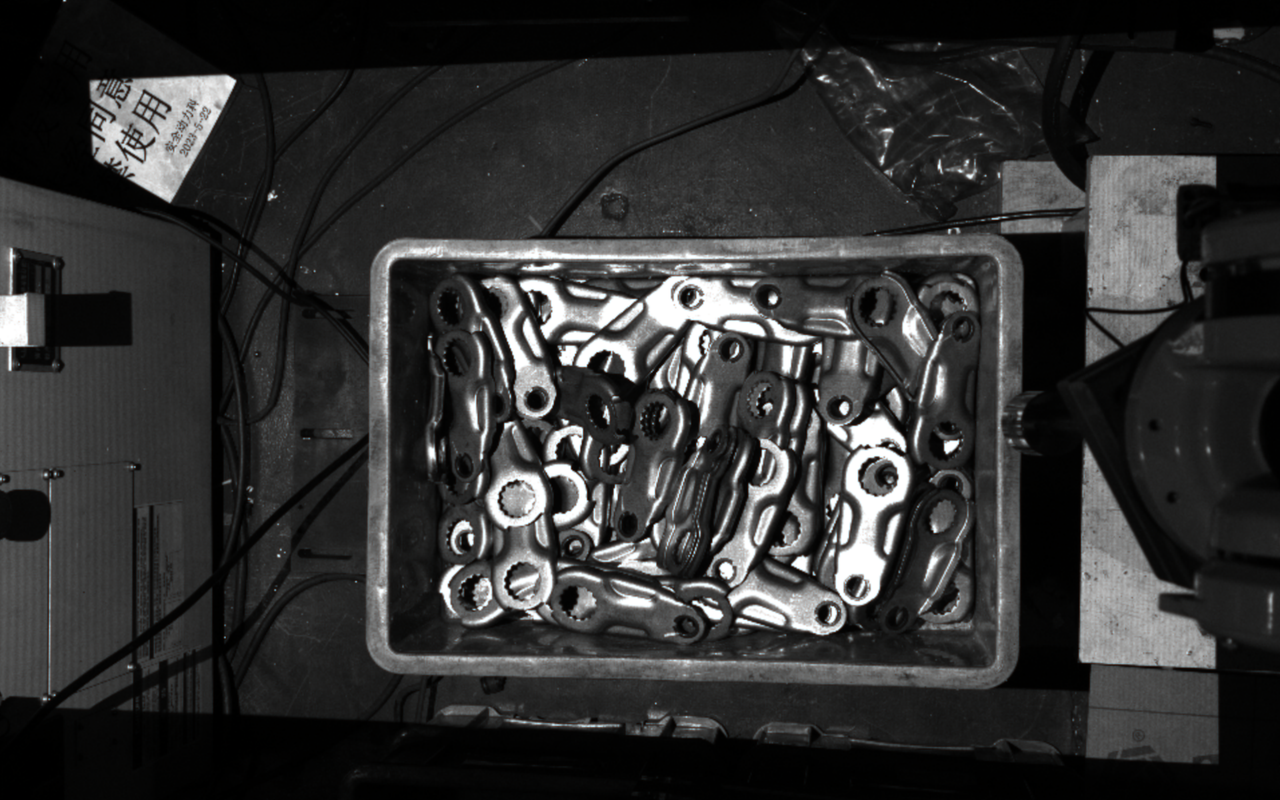  | 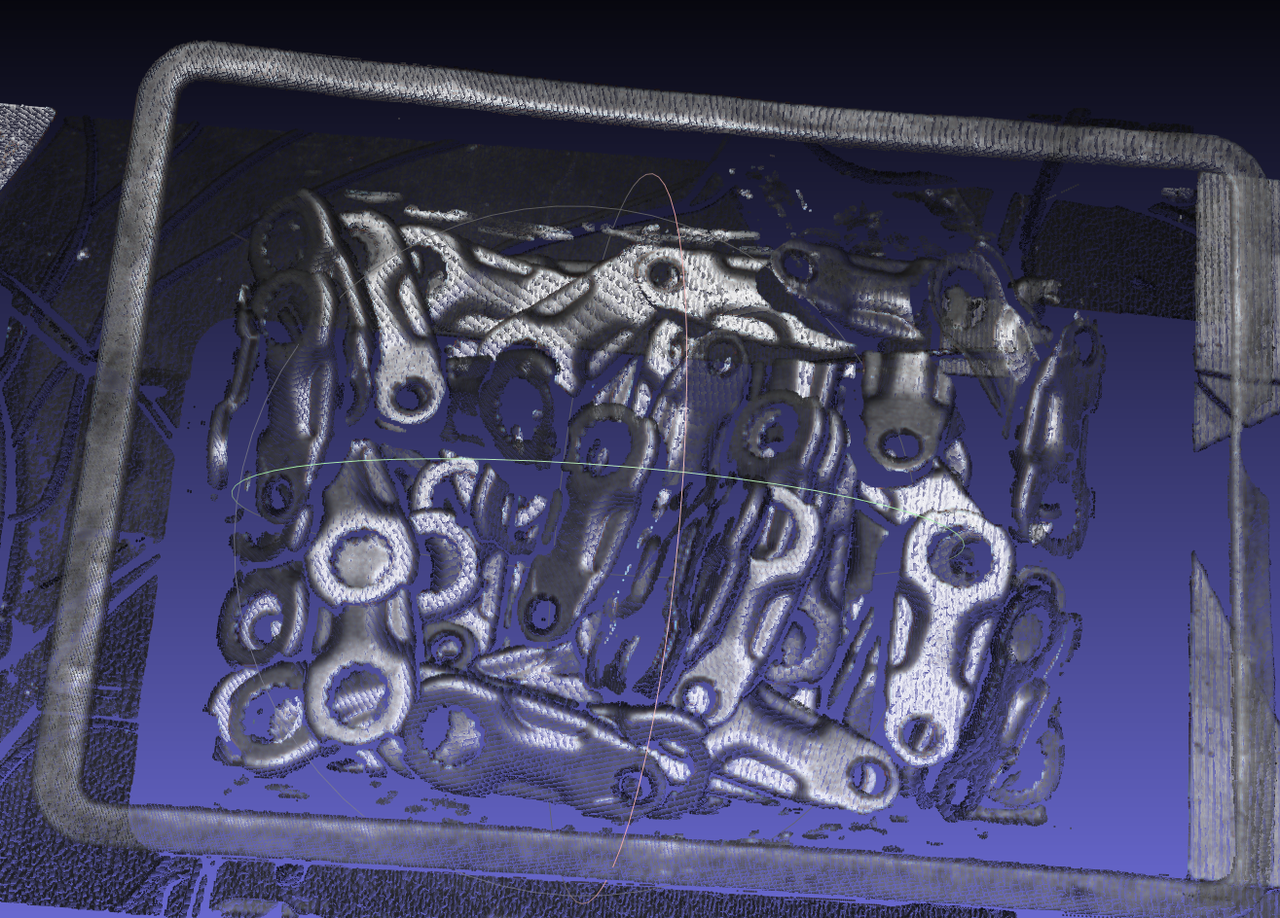 | Direct capture image 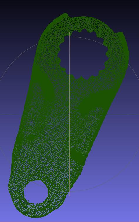 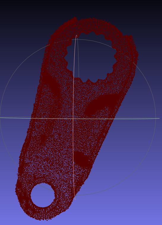 | Preconditions: Workpiece characteristics: self-occlusion, concave shape (with round holes). Basic principles: | Preconditions: Workpiece characteristics: |
| Surface-Type Ordered | 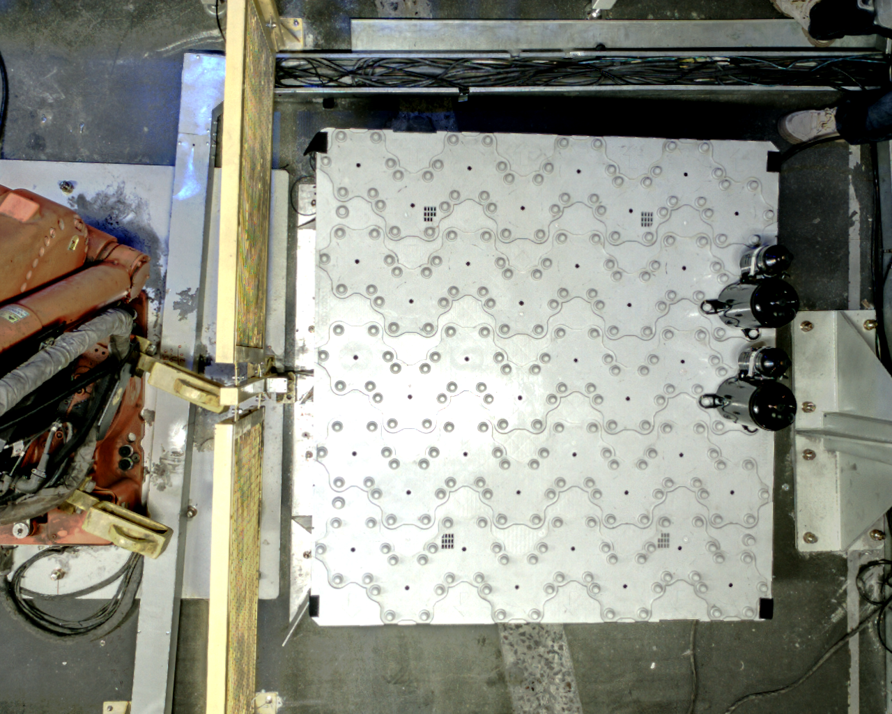  |  |  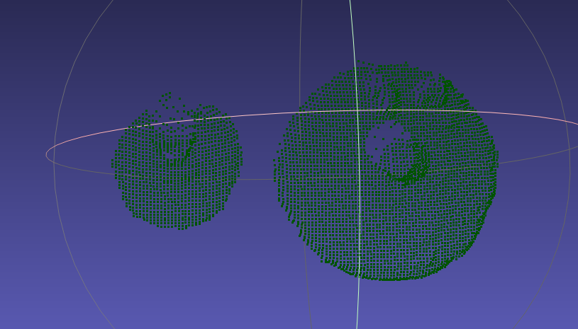 | Preconditions: Workpiece characteristics: three-dimensionality (height difference, curved-surface undulation). Basic principles: | Preconditions: Workpiece characteristics: |
| Surface-Type Ordered |   Process tolerances cause the spatial position of the small can to fluctuate up and down Process tolerances cause the spatial position of the small can to fluctuate up and down | 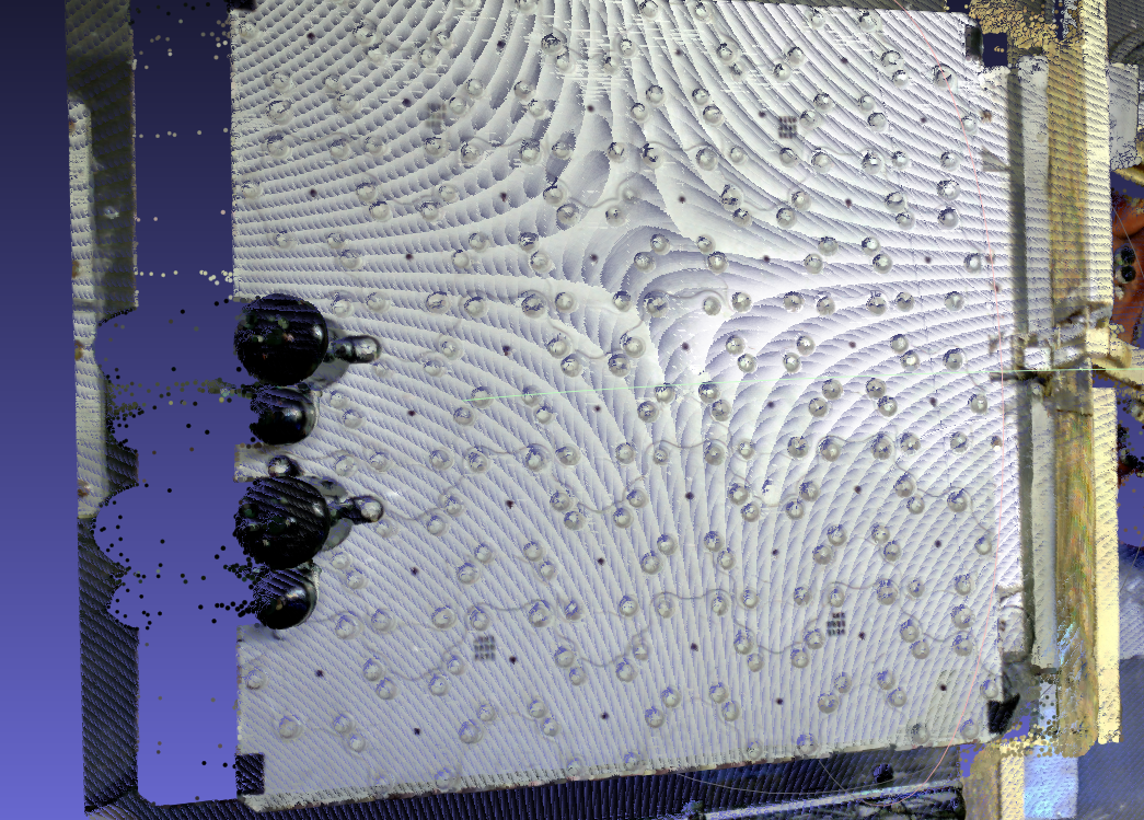 | 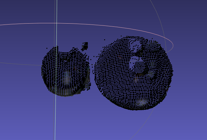 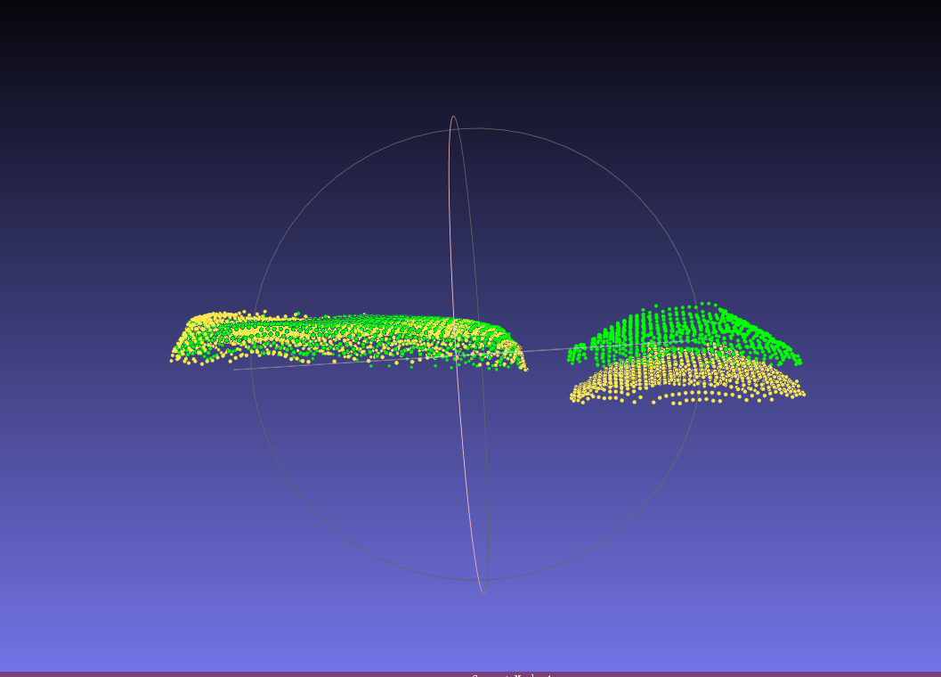 | Preconditions: Workpiece characteristics: three-dimensionality (height difference, curved-surface undulation). Basic principles: | Preconditions: Workpiece characteristics: |
| Surface-Type Unordered | 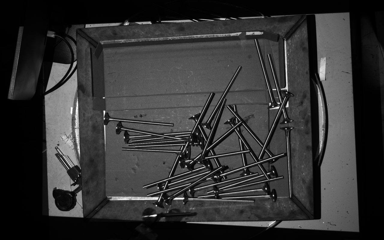 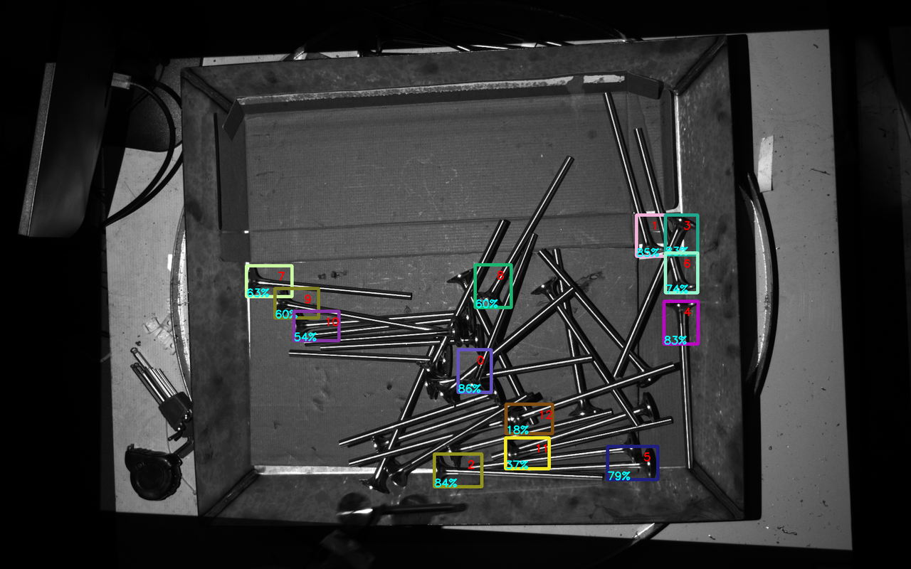 | 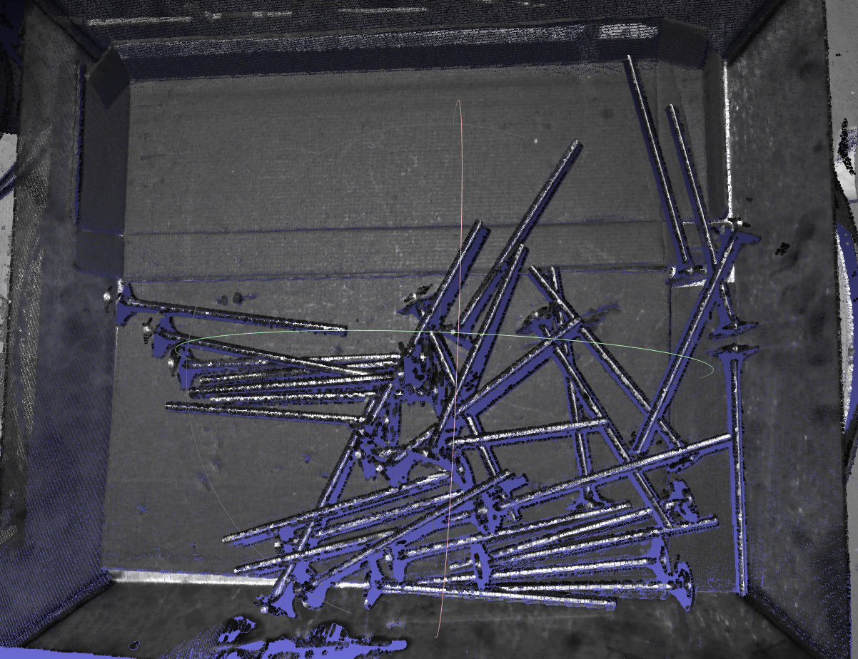 | 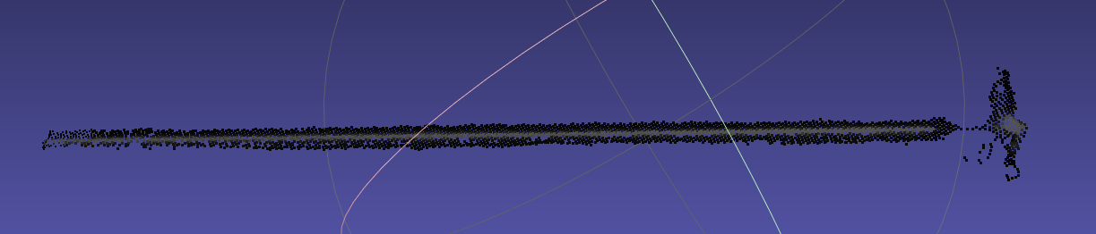 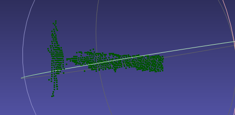 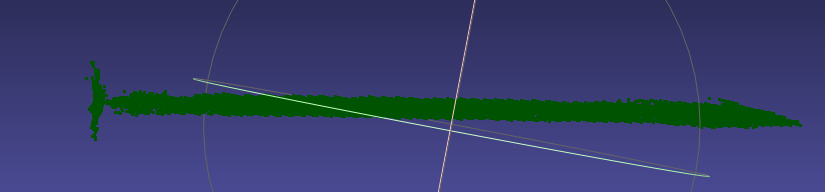 | Preconditions: Workpiece characteristics: symmetric (rotational symmetry), self-occlusion. Basic principles: | Preconditions: Workpiece characteristics: |
| Generic Unordered | 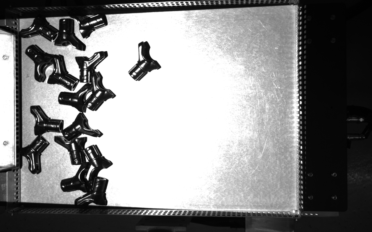 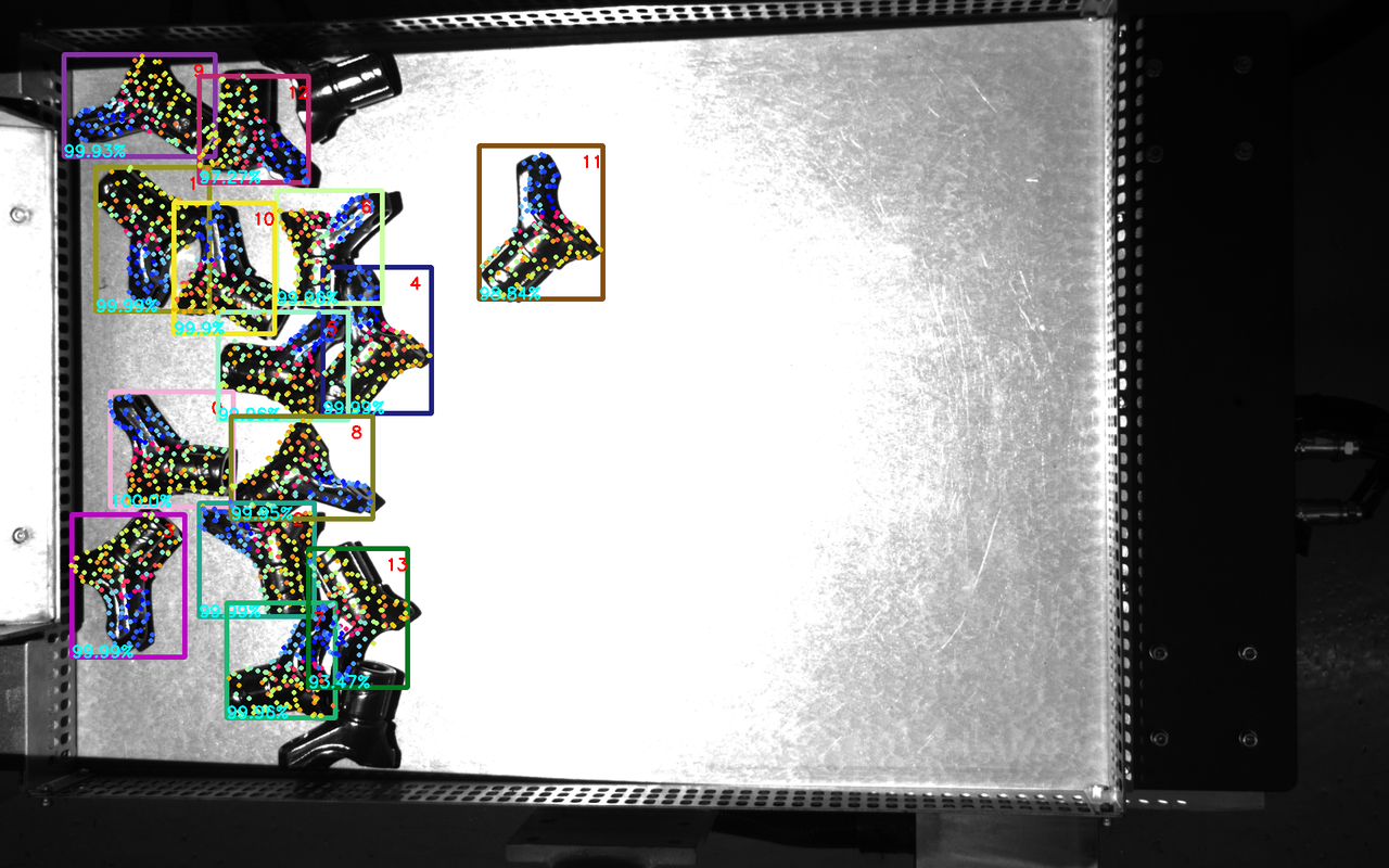 | 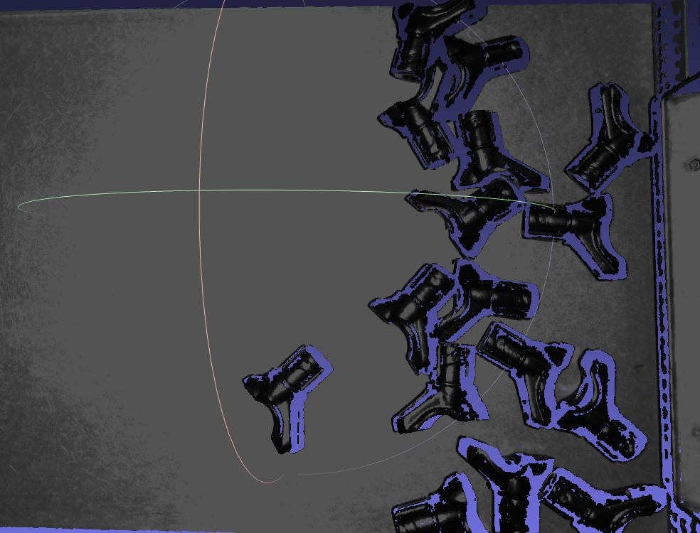 | 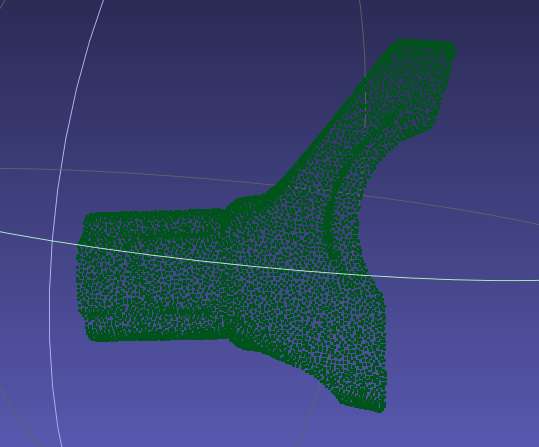 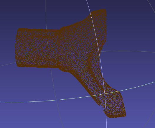 | Preconditions: Based on the scene placement and workpiece characteristics, front and back templates should be used to create the front Point Cloud and back Point Cloud of the workpiece separately, and keypoints should be taken from the overall workpiece. Workpiece characteristics: The workpiece is convex, and convex curved surfaces easily cause reflections, resulting in unstable Point Cloud imaging. Basic principles: | Preconditions: Use PickWiz software to separately generate the front and back Point Cloud templates (current view only), and generate keypoints for the overall workpiece. Workpiece characteristics: Use dual templates based on scene Point Cloud, and the templates must fit the front and back sides of the CAD |
| Surface-Type Positioning and Assembly (Matching Only) | 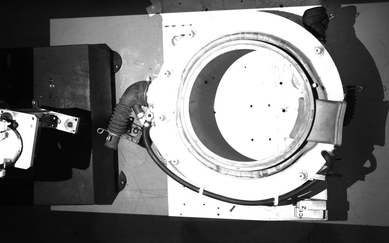 | 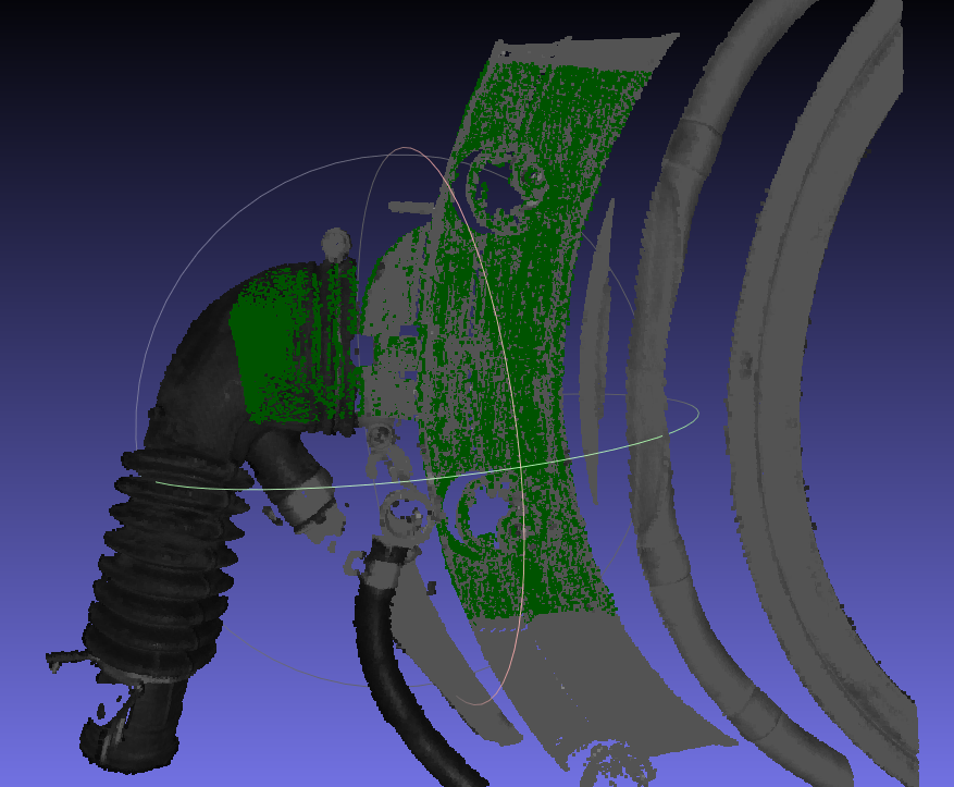 | 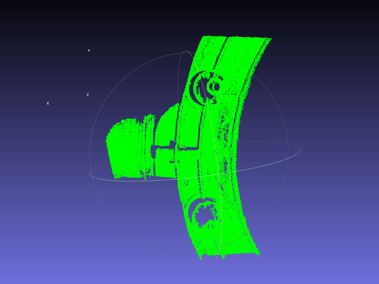 | Preconditions: Workpiece characteristics: Basic principles: | Preconditions: Workpiece characteristics: |
| Generic Positioning and Assembly | 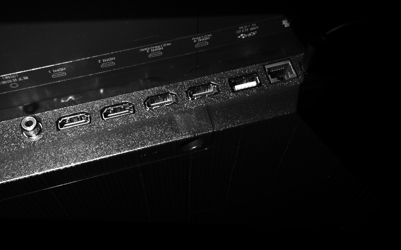 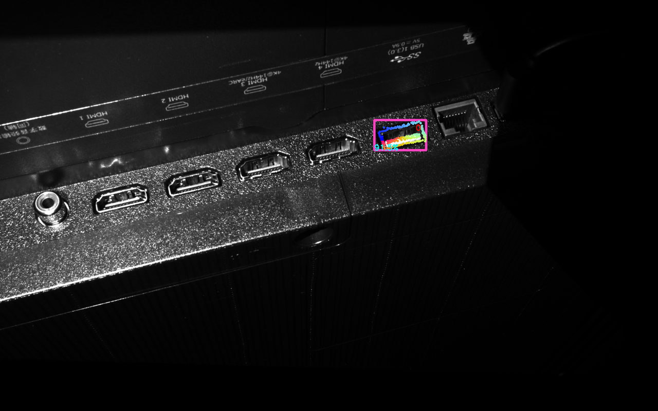 | 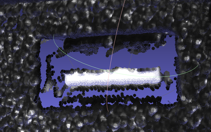 | 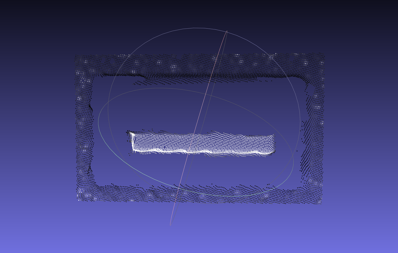 | Preconditions: Workpiece characteristics: Basic principles: | Preconditions: Workpiece characteristics: |