Vision Parameter Adjustment Guide for Planar Workpiece Loading and Unloading (Materials Isolated from Each Other)
This article mainly introduces how to adjust vision parameters according to actual scenarios in planar workpiece loading and unloading (materials isolated from each other).
1. 2D Recognition
1.1 Preprocessing
The preprocessing for 2D Recognition processes 2D images before Instance Segmentation.
1.1.1 Point Cloud Downsampling
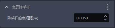
- Function
Sample the Point Cloud according to the specified point spacing to reduce the number of calculated points and improve model inference speed, but accuracy may decrease
- Usage Scenario
Default function for planar workpiece loading and unloading (materials isolated from each other), cannot be deleted
- Parameter Description
| Parameter | Description | Default Value | Parameter Range | Unit |
|---|---|---|---|---|
| Downsampling Point Spacing (m) | Sample the Point Cloud according to the specified point spacing | 0.005 | [0.0001, 1] | m |
Parameter Adjustment
The larger the value of Downsampling Point Spacing, the fewer the Point Clouds after downsampling, the faster the Instance Segmentation calculation speed, but accuracy may decrease
The smaller the value of Downsampling Point Spacing, the more the Point Clouds after downsampling, the slower the Instance Segmentation calculation speed, and the higher the accuracy
1.1.2 Calculate Normal
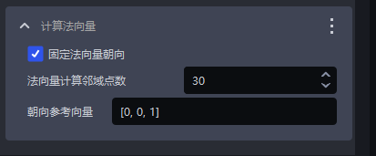
- Function
Calculate the Point Cloud Normal for subsequent Point Cloud processing
- Usage Scenario
Default function for planar workpiece loading and unloading (materials isolated from each other), cannot be deleted
- Parameter Description
| Parameter Name | Description | Default Value | Value Range |
|---|---|---|---|
| Fix Normal Orientation | Whether to fix the orientation when calculating the Normal. After enabled, the Normal is determined by the orientation reference vector | Checked | / |
| Number of Neighboring Points for Normal Calculation | The larger the value, the more neighboring points are referenced, but local changes may be ignored. The smaller the value, the opposite applies | 30 | [1,200] |
| Orientation Reference Vector | Orientation reference vector for Normal calculation | [0,0,1] |
- Parameter Adjustment
Cannot be changed
1.1.3 Fill Holes in the Depth Map
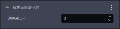
- Function
Fill the hole areas in the depth map and smooth the filled depth map
- Usage Scenario
Due to issues such as obstruction from the workpiece structure itself and uneven lighting, parts of the workpiece may be missing in the depth map
- Parameter Description
| Parameter | Description | Default Value | Value Range |
|---|---|---|---|
| Fill Kernel Size | Size of hole filling | 3 | [1,99] |
Only odd numbers can be entered for the fill kernel size
- Parameter Adjustment
Adjust according to the detection result. If the filling is excessive, reduce the parameter; if the filling is insufficient, increase the parameter
- Example
1.1.4 Filter Point Cloud Based on HSV (Hue, Saturation, Value)
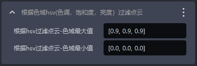
- Function
Filter the Point Cloud based on hue, saturation, and value in the Point Cloud image, and screen out Point Cloud areas matching the target range
- Parameter Description
| Parameter Name | Description | Default Value | Value Range |
|---|---|---|---|
| Filter Depth by HSV - Maximum Color Range Value | Maximum color value for filtering the Point Cloud | [0.9,0.9,0.9] | [[0,0,0],[1,1,1]] |
| Filter Depth by HSV - Minimum Color Range Value | Minimum color value for filtering the Point Cloud | [0.0,0.0,0.0] | [[0,0,0],[1,1,1]] |
- Example
1.1.5 Filter Point Cloud Based on Three-Channel Color
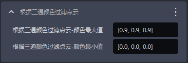
- Function
Filter the Point Cloud based on three-channel color and screen out Point Cloud areas matching the target range
- Parameter Description
| Parameter Name | Description | Default Value | Value Range |
|---|---|---|---|
| Filter Point Cloud by Three-Channel Color - Maximum Color Value | Maximum color value for filtering the Point Cloud | [0.9,0.9,0.9] | [[0,0,0],[1,1,1]] |
| Filter Depth by Three-Channel Color - Minimum Color Value | Minimum color value for filtering the Point Cloud | [0.0,0.0,0.0] | [[0,0,0],[1,1,1]] |
- Example
1.1.6 Remove Points Whose Normals Exceed the Angle Threshold
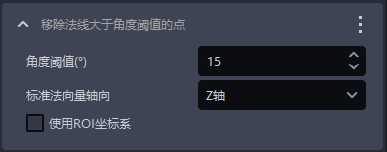
- Function
Remove Point Clouds whose angle between the Normal and the axis direction of the standard Normal is greater than the Normal angle threshold
- Usage Scenario
Planar workpiece loading and unloading (materials isolated from each other)
- Parameter Description
| Parameter Name | Description | Default Value | Value Range | Unit |
|---|---|---|---|---|
| Angle Threshold | Point Clouds greater than this angle threshold are considered different instances | 15 | [-360, 360] | / |
| Standard Normal Axis Direction | The angle formed between the Normal of the Point Cloud and the axis direction of the standard Normal | Z Axis | X/Y/Z Axis | / |
| Whether to Use the ROI Coordinate System | If checked, calculate the angle between the Normal and the axes of the ROI coordinate system; if unchecked, calculate the angle between the Normal and the axes of the Camera coordinate system | Unchecked | / | / |
- Parameter Adjustment
1.1.7 Point Cloud Plane Segmentation
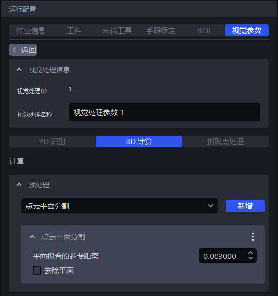
- Function
Retain or remove the plane with the largest number of Point Clouds in the instance Point Cloud
- Usage Scenario
There is a noisy plane in the instance Point Cloud
- Parameter Description
| Parameter | Description | Default Value | Value Range | Unit | Parameter Adjustment Suggestion |
|---|---|---|---|---|---|
| Reference Distance for Plane Fitting | If the distance from a point to the plane is lower than the reference distance, it is considered a point within the plane; otherwise, it is considered a point outside the plane | 0.003 | [0.000001,10] | m | Generally unchanged |
| Whether to Remove the Plane | If checked, remove the plane with the largest number of Point Clouds; if unchecked, retain the plane with the largest number of Point Clouds | Unchecked | / | / | If the plane with the largest number of Point Clouds is the workpiece, retain the plane and leave it unchecked; if the plane with the largest number of Point Clouds is noise, remove the plane and check it |
- Example
1.1.8 Filter Out Point Clouds Whose Object Distance Exceeds the Limit
- Function
Filter out Point Clouds in the specified direction, remove noise points, and improve image recognition accuracy
- Parameter Description
| Parameter | Description | Default Value | Parameter Range | Unit | Parameter Adjustment Suggestion |
|---|---|---|---|---|---|
| Specified Axis | Specified axis of the Point Cloud, used to filter out Point Clouds in the specified direction | Z Axis | X/Y/Z Axis | / | Specified Axis generally does not need to be changed |
| Threshold | Threshold for filtering Point Clouds on the specified axis. Point Clouds whose distance from the workpiece Point Cloud along the specified axis direction is greater than this threshold will be filtered out | 0.75 | [0, 1] | m | Adjust Threshold according to the actual scene. The larger the Threshold, the fewer Point Clouds are filtered out; the smaller the Threshold, the more Point Clouds are filtered out |
| Select Coordinate System | Filter out Point Clouds in the selected coordinate system | ROI Coordinate System | Camera Coordinate System; ROI Coordinate System; Object Coordinate System | / | / |
- Example
1.1.9 Extract the Highest Layer Point Cloud
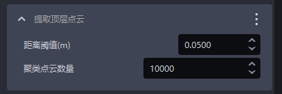
- Function
Extract the Highest Layer Point Cloud based on the depth map and filter out redundant Background Point Clouds
- Usage Scenario
Applicable to planar workpiece loading and unloading (materials isolated from each other). Poor lighting conditions, similar color textures, close stacking, staggered stacking, or occlusion may make it difficult for the model to distinguish texture differences between the upper and lower layers of workpieces, resulting in false detections
- Parameter Description
| Parameter Name | Description | Default Value | Value Range | Unit | Parameter Adjustment Suggestion |
|---|---|---|---|---|---|
| Distance Threshold | If the distance from a point to the top plane (bottom plane) is lower than this threshold, it is considered a point within the top plane (bottom plane) and should be retained; otherwise, it is considered a point on the lower layer (upper layer) and set to black | 0.05 | [0.0001, 1.0000] | m | Generally adjusted to 1/2 of the workpiece height |
| Clustered Point Cloud Count | The expected number of points participating in clustering, namely the number of sampled Point Clouds in the ROI 3D area | 10000 | [1,10000000] | / | The more Clustered Point Cloud Count, the slower the model inference speed and the higher the accuracy; the fewer Clustered Point Cloud Count, the faster the model inference speed and the lower the accuracy |
1.2 Instance Segmentation 3D
1.2.1 Point Cloud Search Radius
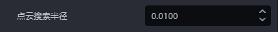
- Function
Points within the search radius are valid points
- Usage Scenario
Planar workpiece loading and unloading (materials isolated from each other) scenario
- Parameter Description
Default value: 0.01
Value range: [0.0001, 1]
Unit: m
- Parameter Adjustment
Greater than the downsampling point spacing and smaller than the minimum distance between the workpiece and noise in the actual scene
1.2.2 Normal Angle Threshold
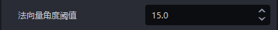
- Function
During Instance Segmentation, points greater than this angle threshold are considered different instances
- Usage Scenario
Planar workpiece loading and unloading (materials isolated from each other) scenario
- Parameter Description
Default value: 15
Value range: [1, 360]
- Parameter Adjustment
Increasing it means segmentation can be considered mainly based on the distance between workpieces; decreasing it may cause incomplete Instance Segmentation
1.2.3 Minimum Point Count Threshold
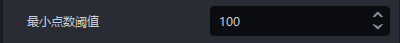
- Function
Retain Point Cloud categories above this value
- Usage Scenario
Planar workpiece loading and unloading (materials isolated from each other) scenario
- Parameter Description
Default value: 100
Value range: [2, 500000]
- Parameter Adjustment
Adjust according to the Point Cloud categories and quantities of instances in the log
1.2.4 Maximum Point Count Threshold
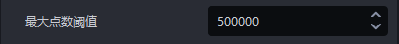
- Function
Retain Point Cloud categories below this value
- Usage Scenario
Planar workpiece loading and unloading (materials isolated from each other) scenario
- Parameter Description
Default value: 5000000
Value range: [2, 500000]
- Parameter Adjustment
Adjust according to the Point Cloud categories and quantities of instances in the log
1.2.5 Instance Segmentation Mode
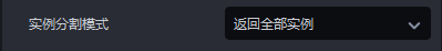
- Function
Which instances to return after Instance Segmentation
- Usage Scenario
Planar workpiece loading and unloading (materials isolated from each other) scenario
- Parameter Description
| Parameter | Description |
|---|---|
| Return All Instances | By default, return all instances that meet the conditions |
| Return the Highest Position Instance (ROI Coordinate System) | Return the instance with the largest Z coordinate in the ROI coordinate system. By default, the Z axis of the ROI coordinate system is vertically upward |
| Return the Instance with the Largest Area | Return the instance with the largest Mask area |
- Example
1.2.6 Use Original Point Cloud

- Function
If checked, the foreground Point Cloud is downsampled and then segmented. If unchecked, the foreground Point Cloud is segmented after 2D preprocessing, downsampling, and clustering
- Usage Scenario
Planar workpiece loading and unloading (materials isolated from each other) scenario
- Parameter Adjustment
Checked by default. After checking this option, the foreground Point Cloud is segmented directly, which can retain more workpiece features; however, the foreground Point Cloud still needs to be downsampled after checking this option, so the Takt Time can be optimized by increasing the downsampling point spacing.
If adhesion is found in the segmentation result, this option should be unchecked to separate adhered instances; after unchecking it, the downsampling point spacing can be reduced according to the segmentation result. If adhesion is not severe, priority can be given to reducing the downsampling point spacing.
1.2.7 Point Cloud Generation
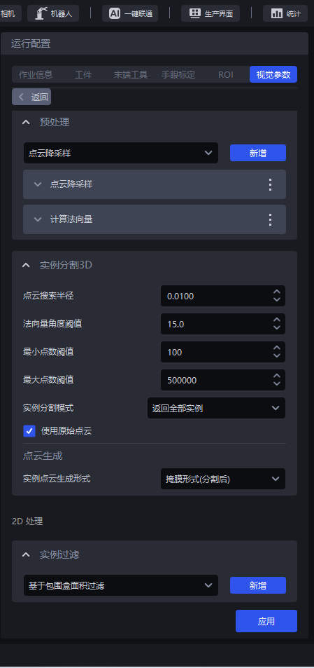
| Instance Point Cloud Generation Method | Mask Method (After Segmentation) | [Deprecated] Point Cloud Generation - Bounding Box Scaling Ratio (After Segmentation) | Use the segmented instance Mask to generate the Point Cloud |
| Bounding Box Method (After Segmentation) | Bounding Box Scaling Ratio (After Segmentation) | Use the segmented instance Bounding Box to generate the Point Cloud | |
| Whether Color Is Required for Generated Point Cloud (After Segmentation) | Whether the generated instance Point Cloud needs attached colors | ||
| Mask Method (After Filtering) | [Deprecated] Point Cloud Generation - Bounding Box Scaling Ratio (After Filtering) | Use the filtered instance Mask to generate the Point Cloud | |
| Bounding Box Method (After Filtering) | Bounding Box Scaling Ratio (After Filtering) | Use the filtered instance Bounding Box to generate the Point Cloud | |
| Whether Color Is Required for Generated Point Cloud (After Filtering) | Whether the generated instance Point Cloud needs attached colors |
- Usage Scenario
(1) If 2D preprocessing deletes the original Point Cloud to filter noise, but the Instance Segmentation 3D node needs to use the complete Point Cloud, "Point Cloud Generation" can be used;
(2) When instances in the scene are discontinuous (for example, split into two clusters of Point Clouds), "Point Cloud Generation" can be used to enlarge the Bounding Box ratio and extract complete but separated instances
- Parameter Adjustment
When Use Original Point Cloud is checked, there is no need to adjust the instance Point Cloud generation method; just use the default parameters.
In the planar workpiece loading and unloading (materials isolated from each other) scenario, after unchecking **Use Original Point Cloud **, Point Cloud clustering is required before Instance Segmentation. The Point Cloud after 2D preprocessing is required for Point Cloud clustering, but the subsequent 3D pose estimation node needs the original Point Cloud, so the optional instance Point Cloud generation function is added.
If the instance Point Cloud generation method is set to Mask Method (After Segmentation) or Mask Method (After Filtering), the instance Point Cloud is generated from the segmented Point Cloud. Because the Point Cloud has been downsampled, the instance Point Cloud generated in Mask method is sparser;
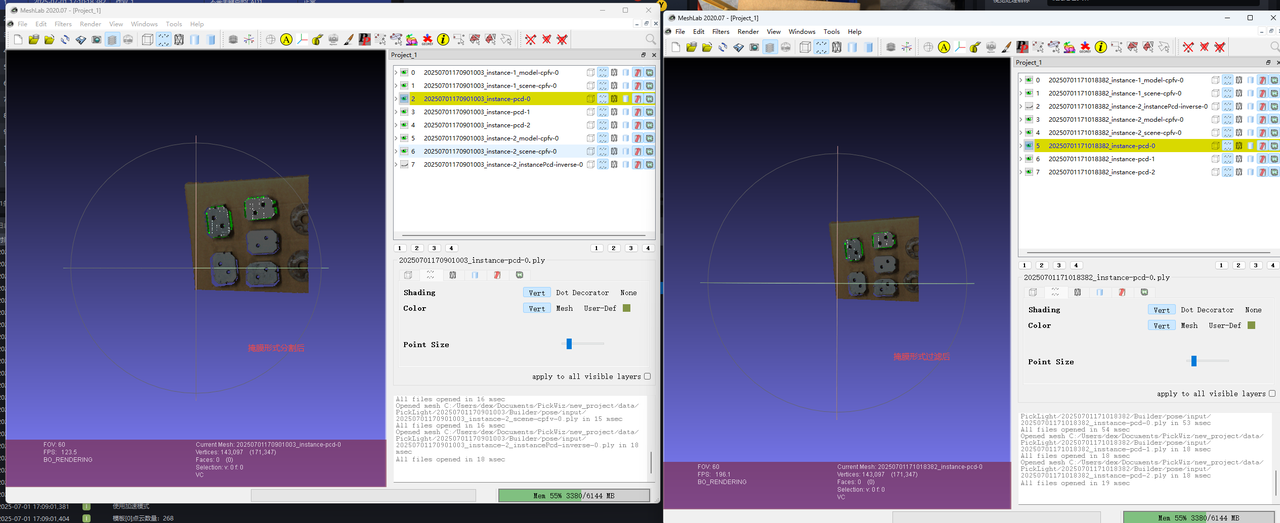
If the instance Point Cloud generation method is set to Bounding Box Method (After Segmentation) or Bounding Box Method (After Filtering), the instance Point Cloud is generated from the original Point Cloud. Because it is the original Point Cloud, the instance Point Cloud generated in Bounding Box method is denser.
1.3 Instance Filtering
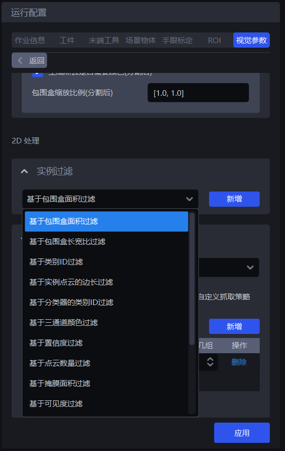
1.3.1 Filter Based on Bounding Box Area
- Feature Overview
Filter based on the pixel area of the Bounding Box of the detected instance.
- Usage Scenario
Applicable to scenes where the instance Bounding Box areas differ greatly. By setting the upper and lower limits of the Bounding Box area, noise in the image can be filtered out, image recognition accuracy can be improved, and time consumed by noise in subsequent processing can be avoided.
- Parameter Description
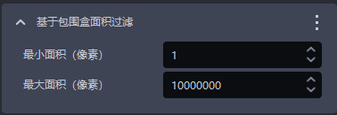
| Parameter | Description | Default Value | Parameter Range | Unit |
|---|---|---|---|---|
| Minimum Area (Pixels) | This parameter is used to set the minimum filtered area of the Bounding Box. Instances whose Bounding Box area is lower than this value will be filtered out | 1 | [1, 10000000] | Pixels |
| Maximum Area (Pixels) | This parameter is used to set the maximum filtered area of the Bounding Box. Instances whose Bounding Box area is higher than this value will be filtered out | 10000000 | [2, 10000000] | Pixels |
- Example
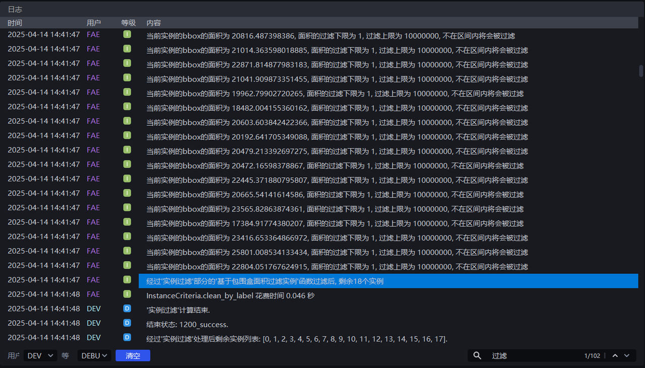
Run with the default value, and you can view the Bounding Box area of each instance in the log, as shown in the figure below.
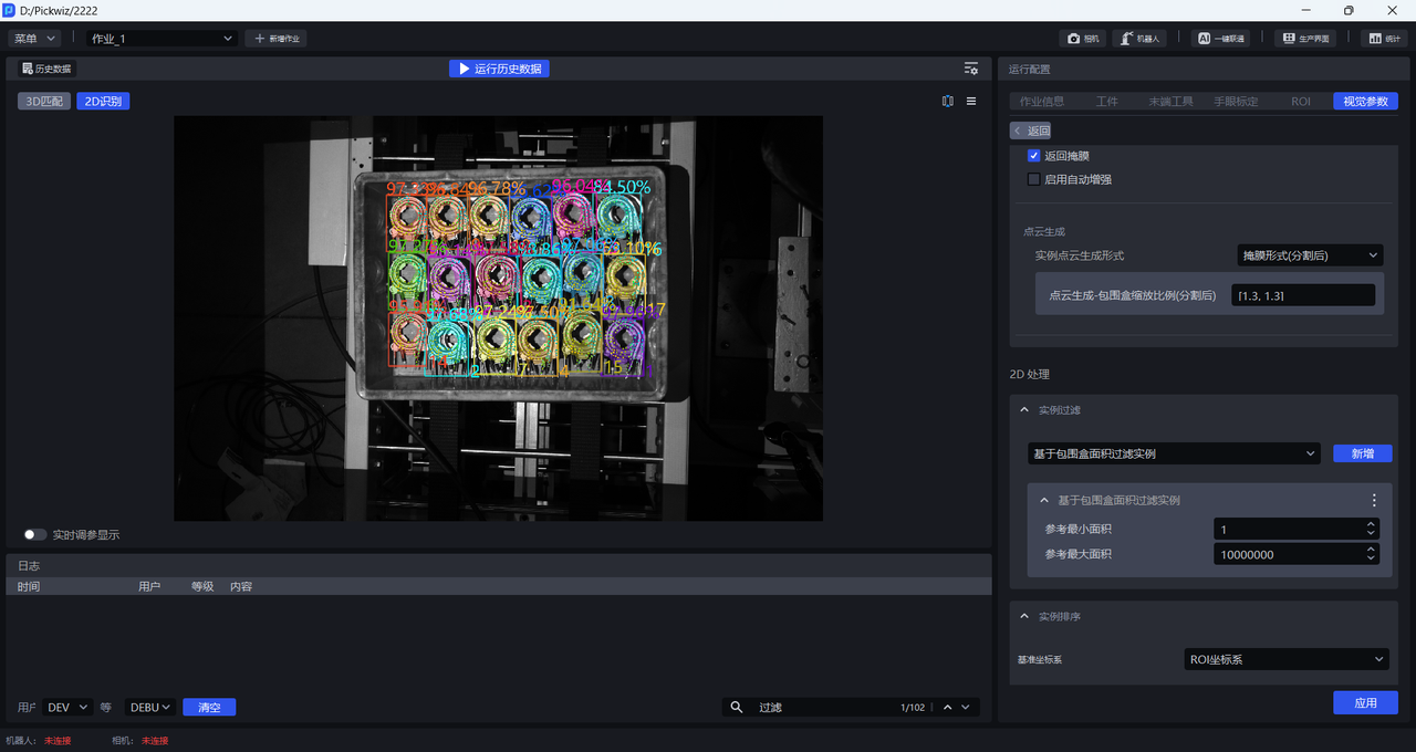
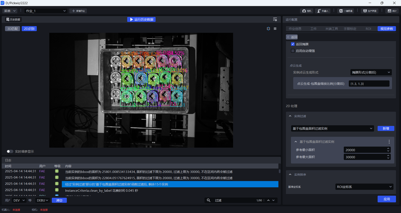
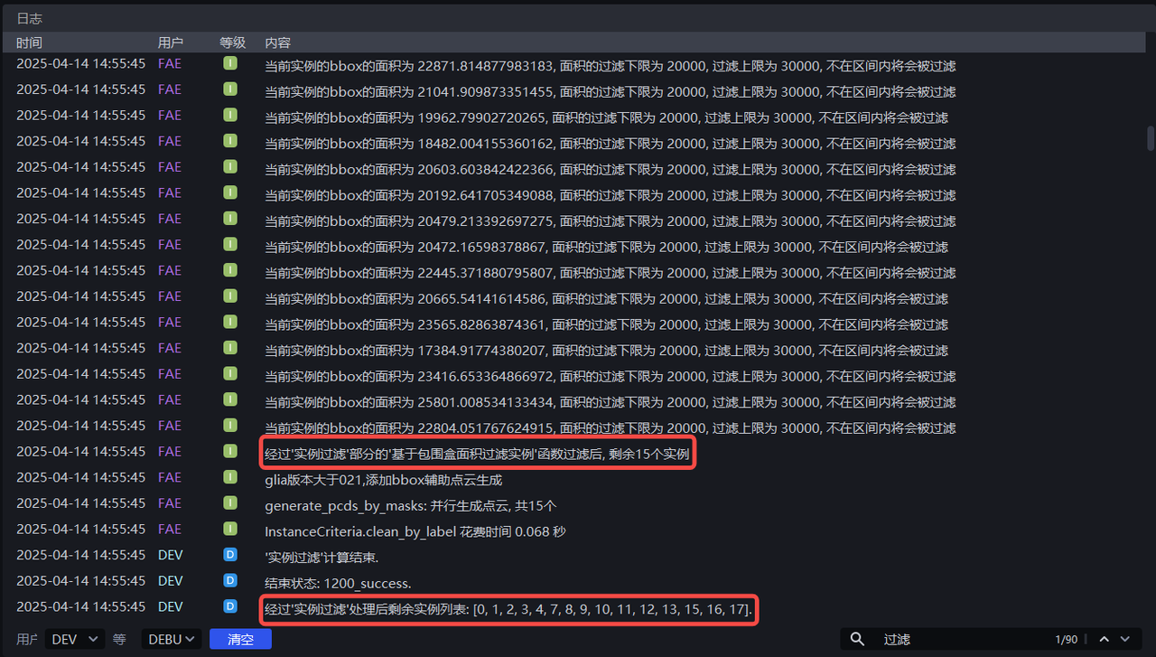
Adjust **Minimum Area ** and Maximum Area according to the Bounding Box area of each instance. For example, set Minimum Area to 20000 and Maximum Area to 30000 to filter out instances whose pixel area is less than 20000 or greater than 30000. The instance filtering process can be viewed in the log.
1.3.2 Filter Based on Bounding Box Aspect Ratio
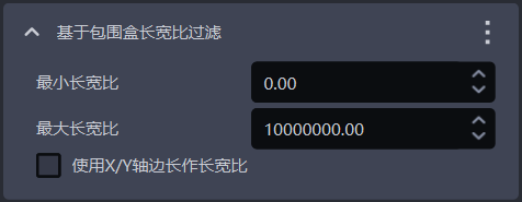
- Feature Overview
Instances whose Bounding Box aspect ratio is outside the specified range will be filtered out
- Usage Scenario
Applicable to scenes where the aspect ratios of instance Bounding Boxes differ greatly
- Parameter Description
| Parameter | Description | Default Value | Parameter Range |
|---|---|---|---|
| Minimum Aspect Ratio | Minimum value of the Bounding Box aspect ratio. Instances whose Bounding Box aspect ratio is lower than this value will be filtered out | 0 | [0, 10000000] |
| Maximum Aspect Ratio | Maximum value of the Bounding Box aspect ratio. Instances whose Bounding Box aspect ratio is higher than this value will be filtered out | 10000000 | [0, 10000000] |
| Use X/Y Axis Side Length as Aspect Ratio | Unchecked by default, the ratio of the longer side / shorter side of the Bounding Box is used as the aspect ratio, which is suitable for cases where the long and short sides of the Bounding Box differ greatly; After checking, the ratio of the side length of the Bounding Box on the X axis / Y axis in the pixel coordinate system is used as the aspect ratio, which is suitable for cases where the long-side/short-side ratios of most normal instance Bounding Boxes are similar, but the ratio of the length on the X axis / the length on the Y axis of some abnormally recognized instance Bounding Boxes differs greatly. | Unchecked | / |
1.3.3 Filter Instances Based on Category ID
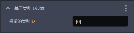
- Feature Overview
Filter by instance category
- Usage Scenario
Applicable to scenes where incoming materials contain multiple types of workpieces
- Parameter Description
| Parameter | Description | Default Value |
|---|---|---|
| Retained Category IDs | Retain instances whose category IDs are in the list, and filter out instances whose category IDs are not in the list | [0] |
- Example
1.3.4 Filter Based on the Side Length of the Instance Point Cloud
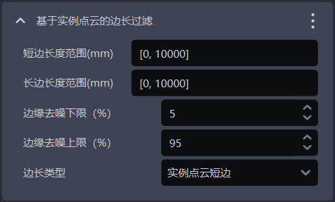
- Feature Overview
Filter based on the long side and short side of the instance Point Cloud
- Usage Scenario
Applicable to scenes where the distances of the instance Point Cloud on the x-axis or y-axis differ greatly. By setting the distance range of the instance Point Cloud, noise in the image can be filtered out, image recognition accuracy can be improved, and time consumed by noise in subsequent processing can be avoided.
- Parameter Description
| Parameter | Description | Default Value | Parameter Range | Unit |
|---|---|---|---|---|
| Short Side Length Range (mm) | Side length range of the short side of the Point Cloud | [0, 10000] | [0, 10000] | mm |
| Long Side Length Range (mm) | Side length range of the long side of the Point Cloud | [0, 10000] | [0, 10000] | mm |
| Lower Limit for Edge Denoising (%) | Extract the lower percentage limit of X/Y values in the instance Point Cloud (Camera coordinate system), and remove Point Clouds outside the upper and lower limits to avoid noise affecting length calculation | 5 | [0, 100] | / |
| Upper Limit for Edge Denoising (%) | Extract the upper percentage limit of X/Y values in the instance Point Cloud (Camera coordinate system), and remove Point Clouds outside the upper and lower limits to avoid noise affecting length calculation | 95 | [0, 100] | / |
| Side Length Type | Filter according to the long side and short side of the instance Point Cloud. Instances whose long side and short side lengths are not within the range will be filtered out | Instance Point Cloud Short Side | Instance Point Cloud Short Side; Instance Point Cloud Long Side; Instance Point Cloud Long Side and Short Side | / |
- Example
1.3.5 Filter Category ID Based on Classifier
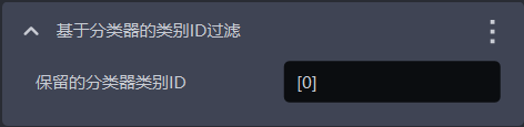
- Feature Overview
Filter instances based on classifier category ID. Instances not in the reference categories will be filtered out.
- Usage Scenario
In multi-category workpiece scenarios, the vision model may detect multiple types of workpieces, but the actual task may require only one category of workpiece. In this case, this function can be used to filter out unnecessary workpieces
- Parameter Description
The default value is [0], which means instances whose category ID is 0 are retained by default, and instances whose category ID is not in the list will be filtered out.
1.3.6 Filter Based on Three-Channel Color
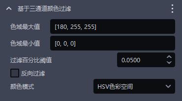
- Feature Overview
Instances can be filtered out using three-channel color thresholds (HSV or RGB).
- Usage Scenario
Cases where incorrect instances and correct instances can be clearly distinguished by color.
- Parameter Description
| Parameter | Description | Default Value | Value Range |
|---|---|---|---|
| Maximum Color Range Value | Maximum color value | [180,255,255] | [[0,0,0],[255,255,255]] |
| Minimum Color Range Value | Minimum color value | [0,0,0] | [[0,0,0],[255,255,255]] |
| Filter Percentage Threshold | Color pass-rate threshold | 0.05 | [0,1] |
| Reverse Filtering | If checked, remove instances whose proportion outside the color range is lower than the threshold; if unchecked, remove instances whose proportion inside the color range in the instance image is lower than the threshold | Unchecked | / |
| Color Mode | The color space selected in color filtering | HSV Color Space | RGB Color SpaceHSV Color Space |
- Example
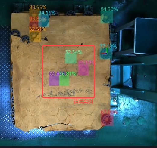
1.3.7 Filter Based on Confidence
- Feature Overview
Filter according to the Confidence score of the instance
- Usage Scenario
Applicable to scenes where the Confidence of instances differs greatly
- Parameter Description
| Parameter | Description | Default Value | Parameter Range |
|---|---|---|---|
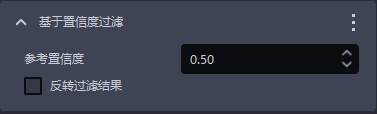
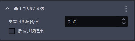
| Reference Confidence Threshold | Retain instances whose Confidence is greater than the threshold, and filter out instances whose Confidence is less than the threshold. | 0.5 | [0,1] |
| Reverse Filter Result | After reversal, retain instances whose visibility Confidence is less than the threshold, and filter out instances whose Confidence is greater than the threshold. | Unchecked | / |
- Example
1.3.8 Filter Based on Point Cloud Quantity
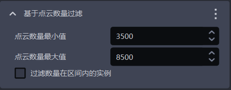
- Feature Overview
Filter according to the quantity of downsampled instance Point Clouds
- Usage Scenario
The instance Point Cloud contains much noise
- Parameter Description
| Parameter | Description | Default Value | Parameter Range |
|---|---|---|---|
| Minimum Point Cloud Quantity | Minimum value of the Point Cloud quantity | 3500 | [1, 10000000] |
| Maximum Point Cloud Quantity | Maximum value of the Point Cloud quantity | 8500 | [2, 10000000] |
| Filter Instances Whose Quantity Is Within the Interval | If checked, filter out instances whose Point Cloud quantity is within the interval between the minimum value and maximum value; if unchecked, filter out instances whose Point Cloud quantity is not within the interval | Unchecked | / |
1.3.9 Filter Based on Mask Area
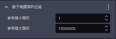
- Feature Overview
Filter image Masks according to the Mask pixel sum (that is, pixel area) of the detected instances.
- Usage Scenario
Applicable to scenes where instance Mask areas differ greatly. By setting the upper and lower limits of the Mask area, noise in the image Mask can be filtered out, image recognition accuracy can be improved, and time consumed by noise in subsequent processing can be avoided.
- Parameter Setting Description
| Parameter Name | Description | Default Value | Parameter Range | Unit |
|---|---|---|---|---|
| Reference Minimum Area | This parameter is used to set the minimum filtered area of the Mask. Instances whose Mask area is lower than this value will be filtered out | 1 | [1, 10000000] | Pixels |
| Reference Maximum Area | This parameter is used to set the maximum filtered area of the Mask. Instances whose Mask area is higher than this value will be filtered out | 10000000 | [2, 10000000] | Pixels |
- Example
1.3.10 Filter Based on Visibility
- Feature Overview
Filter according to the visibility score of the instance
- Usage Scenario
Applicable to scenes where the visibility of instances differs greatly
- Parameter Description
| Parameter | Description | Default Value | Parameter Range |
|---|---|---|---|
| Reference Visibility Threshold | Retain instances whose visibility is greater than the threshold, and filter out instances whose visibility is less than the threshold. Visibility is used to determine how visible an instance is in the image. The more the workpiece is occluded, the lower the visibility. | 0.5 | [0,1] |
| Reverse Filter Result | After reversal, retain instances whose visibility is less than the threshold, and filter out instances whose visibility is greater than the threshold. | Unchecked | / |
1.3.11 Filter Instances with Overlapping Bounding Boxes
- Feature Overview
Filter instances whose Bounding Boxes intersect and overlap
- Usage Scenario
Applicable to scenes where the Bounding Boxes of instances intersect each other
- Parameter Description
| Parameter | Description | Default Value | Parameter Range |
|---|---|---|---|
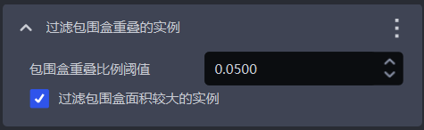
| Bounding Box Overlap Ratio Threshold | Threshold of the ratio of the intersecting area of Bounding Boxes to the area of the instance Bounding Box | 0.05 | [0, 1] |
| Filter Instances with Larger Bounding Box Area | If checked, filter out the instance with the larger area among two instances with intersecting Bounding Boxes; if unchecked, filter out the instance with the smaller area among two instances with intersecting Bounding Boxes | Checked | / |
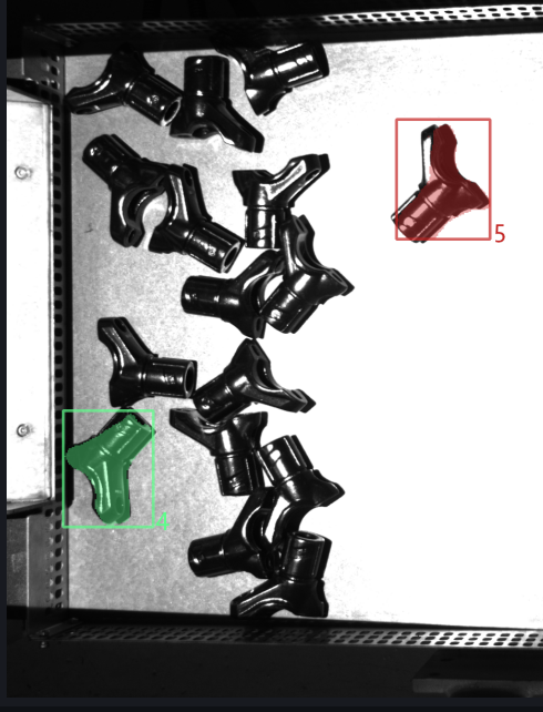
- Example
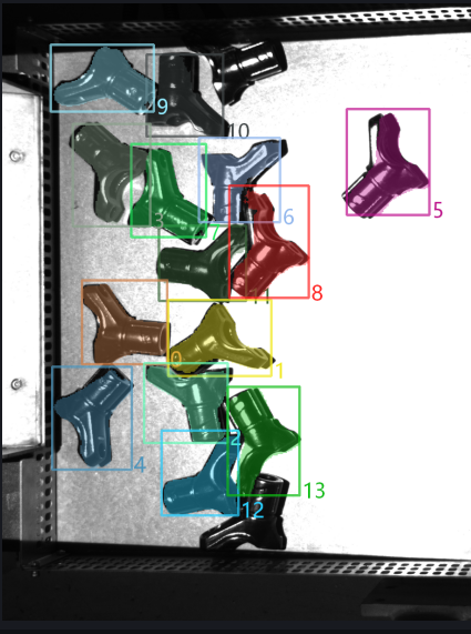
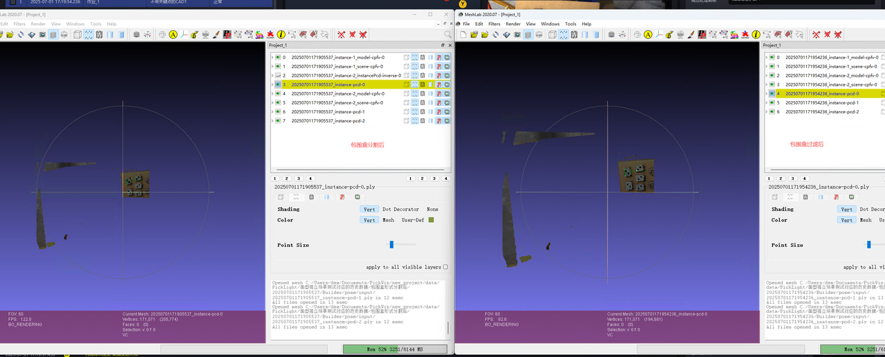
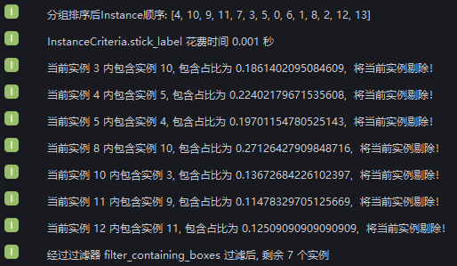
A filter for enclosed instances has been added. Run with the default values and check the intersection of instance Bounding Boxes in the log. After instance filtering, 2 instances remain
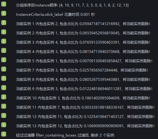
From the log, it can be seen that 12 instances were filtered out due to Bounding Box intersection, leaving 2 instances whose Bounding Boxes do not intersect
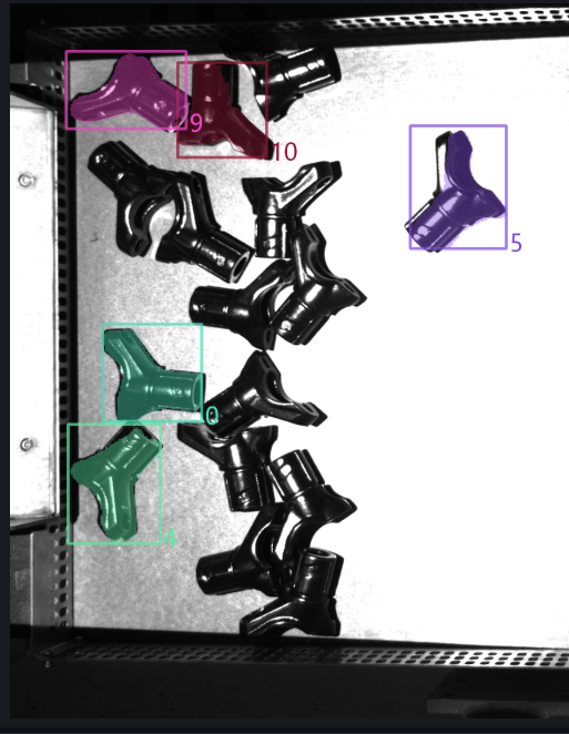
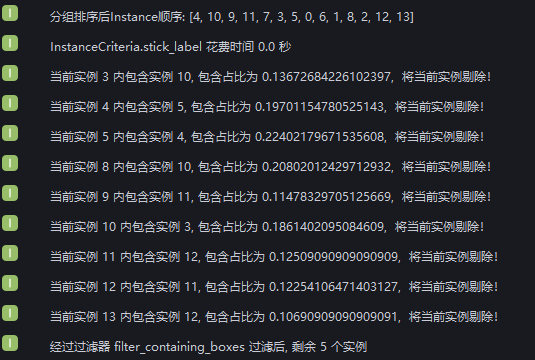
Set Bounding Box Overlap Ratio Threshold to 0.1 and check Whether to Filter Larger Instances. Check the instance filtering process in the log. 9 instances are filtered out because the ratio of the intersecting area of the Bounding Boxes to the area of the instance Bounding Box is greater than 0.1, 3 instances are retained because the ratio is less than 0.1, and 2 instances have no Bounding Box intersection.
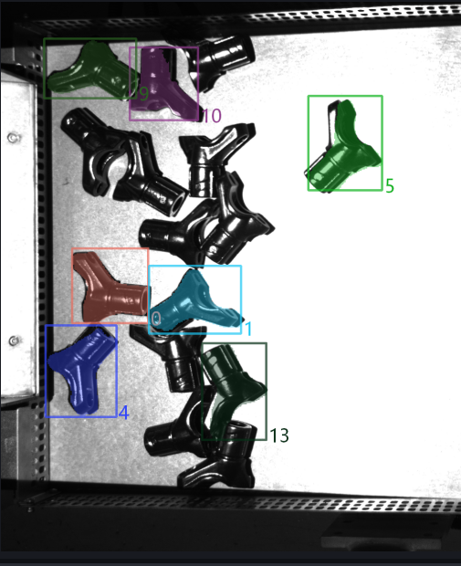
Set Bounding Box Overlap Ratio Threshold to 0.1 and uncheck Whether to Filter Larger Instances. Check the instance filtering process in the log. The ratio of the intersecting area of the Bounding Boxes to the area of the instance Bounding Box is greater than 0.1 for 9 instances, but 2 of those instances are retained because their Bounding Box areas are smaller than the instances intersecting with them. Therefore, 7 instances are filtered out, 3 instances are retained because the ratio of the intersecting area of the Bounding Boxes to the area of the instance Bounding Box is less than 0.1, and 2 instances have no Bounding Box intersection.
1.3.12 [Advanced] Filter Concave-Convex Instances Based on the Mask/Enclosing Polygon Area Ratio
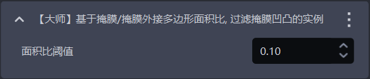
- Feature Overview
Calculate the area ratio of the Mask / enclosing polygon. If it is lower than the set threshold, the instance will be filtered out
- Usage Scenario
Applicable to cases where the workpiece Mask has jagged edges / concave-convex surfaces.
- Parameter Description
| Parameter | Description | Default Value | Value Range |
|---|---|---|---|
| Area Ratio Threshold | Mask / convex hull area ratio threshold. If it is lower than the set threshold, the instance will be filtered out. | 0.1 | [0,1] |
1.3.13 [Advanced] Filter Based on Average Point Cloud Distance
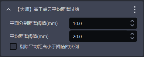
- Feature Overview
Filter based on the average value of the distances from points in the Point Cloud to the fitted plane, and remove uneven instance Point Clouds
- Usage Scenario
Applicable to scenarios where planar workpiece Point Clouds are bent
- Parameter Description
| Parameter | Description | Default Value | Parameter Range | Unit |
|---|---|---|---|---|
| Plane Segmentation Distance Threshold (mm) | Extract a plane from the bent instance Point Cloud. Points whose distance from the plane is less than this threshold are regarded as points on the plane | 10 | [-1000, 1000] | mm |
| Average Distance Threshold (mm) | Average value of the distances from points in the instance Point Cloud to the extracted plane | 20 | [-1000, 1000] | mm |
| Remove Instances Whose Average Distance Is Less Than the Threshold | If checked, filter out instances whose average distance from points to the extracted plane is less than the average distance threshold; if unchecked, filter out instances whose average distance from points to the extracted plane is greater than the average distance threshold | Unchecked | / | / |
1.3.14 [Advanced] Filter Occluded Instances Based on the Mask/Bounding Box Area Ratio
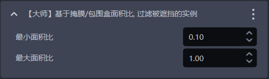
- Feature Overview
Calculate the area ratio of the Mask / Bounding Box. Instances whose ratio is not within the maximum and minimum range will be filtered out
- Usage Scenario
Used to filter instances of occluded workpieces
- Parameter Description
Conversely, it indicates that the instance may be occluded.
| Parameter | Description | Default Value | Value Range |
|---|---|---|---|
| Minimum Area Ratio | Lower limit of the Mask / Bounding Box area ratio range. The smaller the ratio, the higher the occlusion degree of the instance | 0.1 | [0,1] |
| Maximum Area Ratio | Upper limit of the Mask / Bounding Box area ratio range. The closer the ratio is to 1, the lower the occlusion degree of the instance | 1.0 | [0,1] |
1.3.15 [Advanced] Determine Whether All Highest Layer Instances Have Been Fully Detected
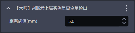
- Feature Overview
This is one of the error-proofing mechanisms. It determines whether all instances on the Highest Layer have been detected. If any Highest Layer instances have not been detected, an error will be reported and the Workflow will end
- Usage Scenario
Applicable to scenarios where one photo is used for multiple picks or where picking must be performed in sequence, to prevent missed picks caused by incomplete instance detection from affecting subsequent tasks
- Parameter Description
| Parameter | Description | Default Value | Parameter Range | Unit | Parameter Adjustment |
|---|---|---|---|---|---|
| Distance Threshold | Used to determine the Highest Layer workpiece. If the distance between a point and the highest point of the workpiece Point Cloud is less than the distance threshold, the point is regarded as a Highest Layer Point Cloud point; otherwise, it is not regarded as a Highest Layer Point Cloud point. | 5 | [0.1, 1000] | mm | It should be less than the height of the workpiece |
1.4 Instance Sorting
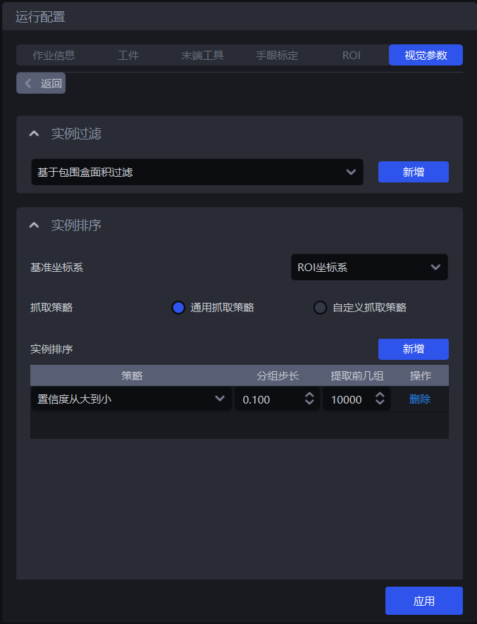
- Feature Overview
Group, sort, and extract instances according to the selected strategy
- Usage Scenario
Common to unordered picking scenarios and ordered loading and unloading scenarios
If sorting is not required, no specific strategy needs to be configured.
1.4.1 Reference Coordinate System
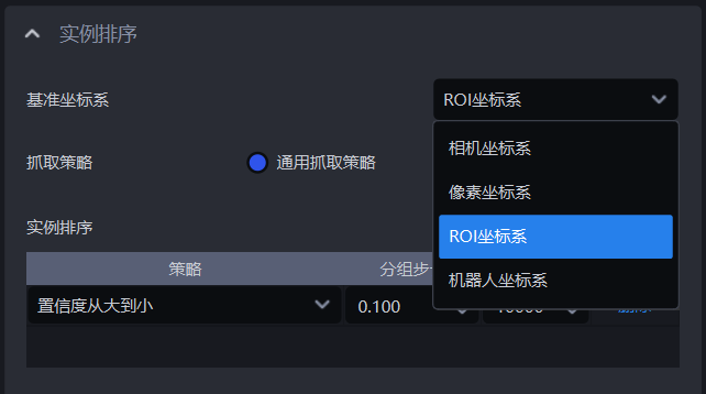
- Feature Overview
Set a unified coordinate system for all instances to group and sort instances
- Usage Scenario
Common to depalletizing scenarios, unordered picking scenarios, and ordered loading and unloading scenarios
Coordinate-related strategies should set the reference coordinate system first
- Parameter Description
| Parameter | Description | Illustration |
|---|---|---|
| Camera Coordinate System | The coordinate system origin is above the object, and the positive Z-axis direction points downward; XYZ values are the values of the object center point in this coordinate system | 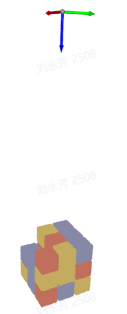 |
| ROI Coordinate System | The coordinate system origin is approximately at the pallet center, and the positive Z-axis direction points upward; XYZ values are the values of the object center point in this coordinate system | 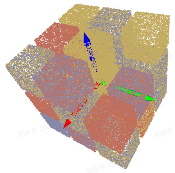 |
| Robot Coordinate System | The coordinate system origin is on the Robot itself, and the positive Z-axis direction generally points upward; XYZ values are the values of the object center point in this coordinate system | 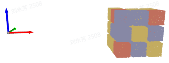 |
| Pixel Coordinate System | The coordinate system origin is at the left top point of the RGB image and is a two-dimensional plane coordinate system; X and Y values are the x value and y value of the bbox recognition box, and Z is 0 | 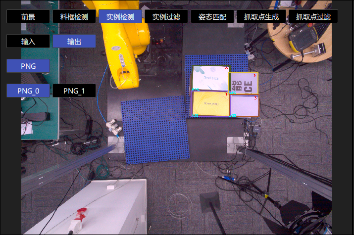 |
1.4.2 General Pick Strategy
- Parameter Description
| Parameter | Description | Default Value |
|---|---|---|
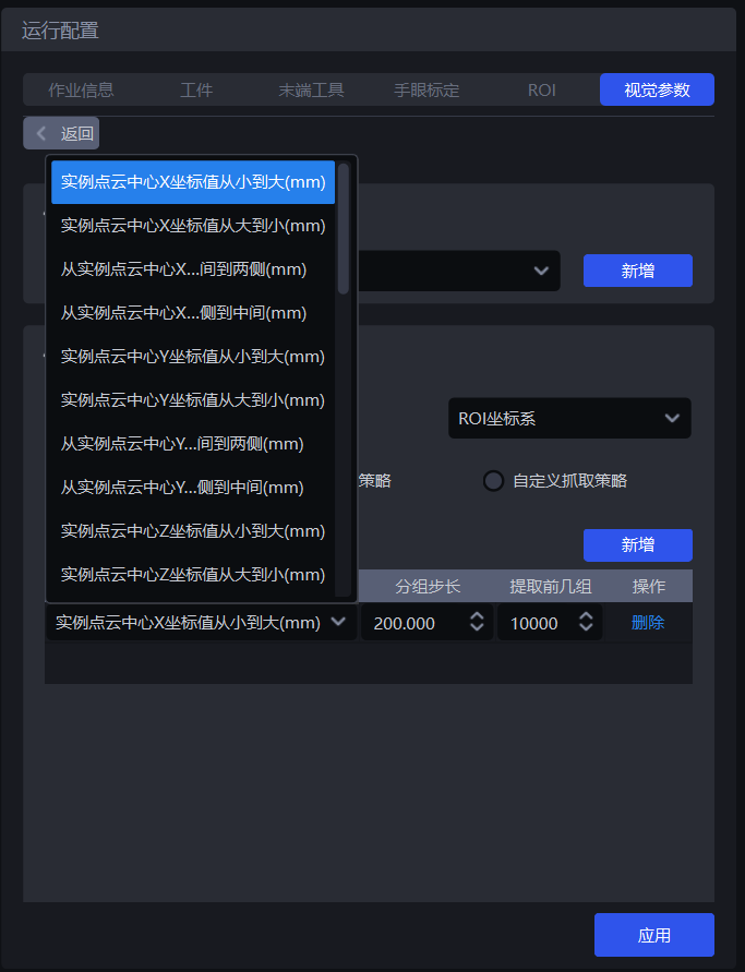
| Strategy | Select which value to use for grouping and sorting and how to sort, including multiple items such as XYZ coordinate values of the instance Point Cloud center, Bounding Box aspect ratio, and the distance from the instance Point Cloud center to the ROI center, which can be superimposed and executed in sequence | Instance Point Cloud Center X Coordinate Value from Small to Large (mm) |
| Grouping Step Size | According to the selected strategy, instances are divided into several groups based on the step size. The grouping step size is the interval between two groups of instances. For example, if the strategy selects "Instance Point Cloud Center Z Coordinate Value from Large to Small (mm)", all instance Point Cloud center Z coordinates will be sorted from large to small, and then grouped by the step size, and the corresponding instances will also be divided into several groups | / |
| Extract Top Groups | After grouping and sorting, how many groups of instances need to be retained | 10000 |
| Strategy Name* | Description | Grouping Step Size | Extract Top Groups | |
|---|---|---|---|---|
| Default Value | Value Range | Default Value | ||
| Instance Point Cloud Center XYZ Coordinate Value from Large to Small / from Small to Large (mm) | Use the XYZ coordinate values of the Point Cloud center of each instance for grouping and sorting The reference coordinate system should be set before using this strategy for sorting | 200.000 | (0, 10000000] | 10000 |
| From the Middle to Both Sides of the Instance Point Cloud Center XY Coordinate Axis / from Both Sides to the Middle of the Instance Point Cloud Center XY Coordinate Axis (mm) | Use the XY coordinate values of the Point Cloud center of each instance for grouping and sorting in the direction of "from the middle to both sides" or "from both sides to the middle" The reference coordinate system should be set before using this strategy for sorting | 200.000 | (0, 10000000] | 10000 |
| Bounding Box Center XY Coordinate Value from Large to Small / from Small to Large (mm) | Use the XY coordinate values of the Bounding Box center point of each instance in the pixel coordinate system for grouping and sorting | 200.000 | (0, 10000000] | 10000 |
| Bounding Box Aspect Ratio from Large to Small / from Small to Large | Use the ratio of the long side / width side of the Bounding Box for grouping and sorting | 1 | (0, 10000] | 10000 |
| From the Middle to Both Sides of the Bounding Box Center XY Coordinate Axis / from Both Sides to the Middle (mm) | Use the XY coordinate values of the Bounding Box center point for grouping and sorting in the direction of "from the middle to both sides" or "from both sides to the middle" | 200.000 | (0, 10000000] | 10000 |
| Workpiece Type ID from Large to Small / from Small to Large | Use the ID of the workpiece type for grouping and sorting, suitable for multi-category workpiece scenarios | 1 | [1, 10000] | 10000 |
| Local Feature ID from Large to Small / from Small to Large | Use the ID of the local feature for grouping and sorting | 1 | [1, 10000] | 10000 |
| Confidence from Large to Small / from Small to Large | Use the Confidence of each instance for grouping and sorting | 1 | (0, 1] | 10000 |
| Visibility from Small to Large / from Large to Small | Use the visibility of each instance for grouping and sorting | 1 | (0, 0.1] | 10000 |
| Mask Area from Large to Small / from Small to Large | Use the Mask area of each instance for grouping and sorting | 10000 | [1, 10000000] | 10000 |
| Distance from Instance Point Cloud Center to ROI Center from Near to Far / from Far to Near (mm) | Use the distance from the Point Cloud center of each instance to the center of the ROI coordinate system for grouping and sorting | 200.000 | (0, 10000000] | 10000 |
| Distance from Instance Point Cloud Center to Robot Coordinate Origin from Near to Far / from Far to Near (mm) | Use the distance from the Point Cloud center of each instance to the origin of the Robot coordinate system for grouping and sorting | 200.000 | (0, 10000000] | 10000 |
- Example
1.4.3 Custom Pick Strategy
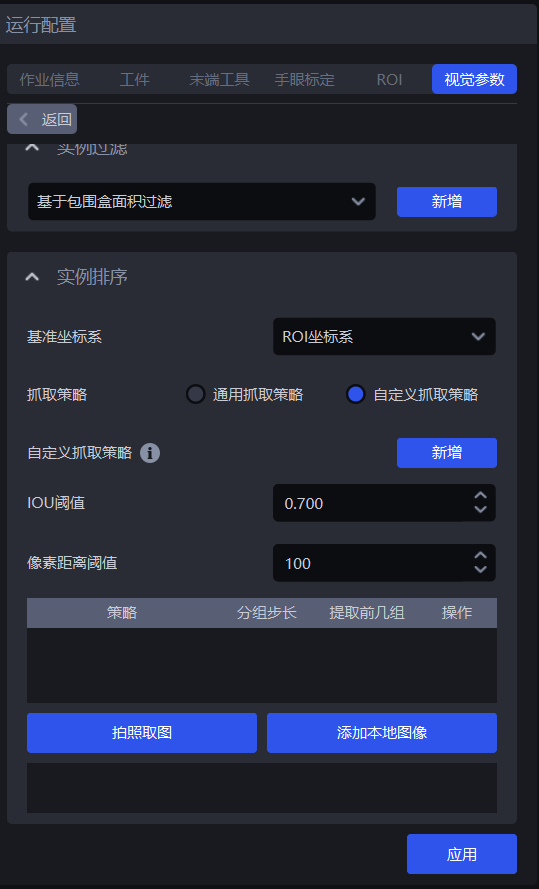
(1) Function Description
Switch grasping strategy to Custom grasping strategy, then click Add to add a custom pick strategy.
Customize the picking sequence for each workpiece. If it is difficult to achieve picking with the general pick strategy, or if it is hard to tune suitable parameters because of Point Cloud noise and other issues, you can consider using a custom pick strategy
Custom pick strategies are suitable for depalletizing scenarios and ordered loading and unloading scenarios, but not for unordered picking scenarios, because the workpieces in a custom pick strategy must be ordered (that is, the workpiece order is fixed)
A custom pick strategy can only be combined with a single general pick strategy, and the strategy can only select the Z coordinate from small to large
(2) Parameter Description
| Parameter | Description | Default Value | Value Range | Parameter Adjustment |
|---|---|---|---|---|
| IOU Threshold | Represents the overlap threshold between the annotated bbox and the detected bbox, and determines which image sorting method should be selected for the current workpiece instance sorting through the overlap. | 0.7 | [0,1] | The larger the threshold, the stricter the matching and the worse the anti-interference capability. Small shape or position changes may cause matching failure, which may match the wrong custom strategy and sort in the wrong order |
| Pixel Distance Threshold | Represents the dimensional difference between the matched bbox and the detected bbox. | 100 | [0,1000] | The smaller the threshold, the stricter the matching and the better the anti-interference capability. If the workpiece placement between different layers is similar, it may also mismatch the custom strategy, resulting in an incorrect sorting order. |
(3) Select the Reference Coordinate System
When using a custom pick strategy, only the Camera coordinate system or Pixel coordinate system can be selected
If there are multiple layers of workpieces, select the Camera coordinate system; if there is only one layer of workpieces, select the pixel coordinate system
(4) Strategy, Grouping Step Size, and Extract Top Groups
| Parameter | Description | Default Value |
|---|---|---|
| Strategy | Only Instance Point Cloud Center Z Coordinate Value from Large to Small / from Small to Large (mm) can be selected | / |
| Grouping Step Size | According to the strategy of Z coordinate from small to large, sort the Z coordinates of instances from small to large, and divide instances into several groups according to the step size | 10000 |
| Extract Top Groups | After grouping and sorting, how many groups of instances need to be retained | 10000 |
(5) Capture Image / Add Local Image
Click Capture Image to obtain an image from the currently connected Camera, or click Add Local Image to import an image from local storage. For however many layers there are or however many different placement patterns of workpieces there are, that many images need to be obtained by capturing or adding local images. If every layer is the same, only one image is needed. Right-click an image to delete it.
On the obtained image, click and hold the left mouse button and drag to annotate the bbox. The DELETE key can gradually delete the annotated bbox.
2. 3D Calculation
2.1 Preprocessing
The preprocessing for 3D Calculation processes 3D Point Clouds before calculation by the Deep Learning model
2.1.1 Point Cloud Clustering Denoising
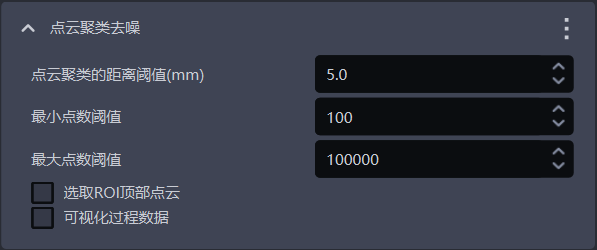
- Function
Remove noise by Point Cloud clustering
- Usage Scenario
There is much noise in the instance Point Cloud
Point Cloud clustering denoising may filter out part of the workpiece Point Cloud because the workpiece Point Cloud is adhered to the noise Point Cloud
- Parameter Description
| Parameter Name | Description | Default Value | Value Range | Unit | Parameter Adjustment Suggestion |
|---|---|---|---|---|---|
| Distance Threshold for Point Cloud Clustering (mm) | Determine whether Point Clouds in space belong to the same category. If the distance between Point Clouds is lower than this threshold, they are regarded as the same category | 5 | [0.1, 1000] | mm | Generally, no change is needed. It should be greater than the point spacing of the workpiece Point Cloud and smaller than the minimum distance between the workpiece Point Cloud and the noise Point Cloud |
| Minimum Point Count Threshold | Point Cloud clusters smaller than this point count will be filtered out | 100 | [1,10000000] | / | Generally, no change is needed. Increase the Minimum Point Count Threshold according to the amount of noise in the instance Point Cloud |
| Maximum Point Count Threshold | Point Cloud clusters larger than this point count will be filtered out | 100000 | [1,10000000] | / | Generally, no change is needed. If the quantity of workpiece Point Clouds is greater than 100000, increase the Maximum Point Count Threshold |
| Whether to Select the Point Cloud at the Top of the ROI | If checked, calculate and sort the average Z coordinate values of Point Clouds of the same category in the ROI coordinate system, and retain the Point Cloud category with the largest average Z coordinate value (top Point Cloud). If unchecked, retain all Point Clouds that meet the conditions | Unchecked | / | / | If the workpiece Point Cloud is above the noise Point Cloud, checking it retains the workpiece Point Cloud; if the workpiece Point Cloud is below the noise Point Cloud, when checking it, the Z-axis of the ROI coordinate system should be adjusted downward to retain the workpiece Point Cloud |
| Whether to Visualize Process Data | If checked, save the denoised Point Cloud, which can be viewed in C:_data | Unchecked | / | / | In debugging mode, check it if visualized data needs to be saved |
- Example
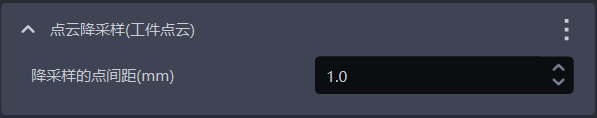
2.1.2 Point Cloud Downsampling
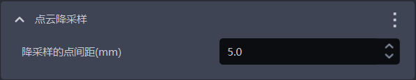
- Function
Sample the Point Cloud according to the specified point spacing to reduce the number of calculated points and improve model inference speed, but accuracy may decrease
- Usage Scenario
If there are too many Point Clouds, check Point Cloud Downsampling to reduce the number of Point Clouds. This is a default function for planar workpiece loading and unloading (materials isolated from each other) and cannot be deleted.
- Parameter Description
| Parameter | Description | Default Value | Parameter Range | Unit |
|---|---|---|---|---|
| Downsampling Point Spacing (mm) | Sample the Point Cloud according to the specified point spacing | 5.0 | [0.1, 1000] | mm |
Parameter Adjustment
The larger the value of Downsampling Point Spacing, the fewer Point Clouds after downsampling, the faster the Pick Point calculation speed, but accuracy may decrease
The smaller the value of Downsampling Point Spacing, the more Point Clouds after downsampling, the slower the Pick Point calculation speed, and the higher the accuracy
2.1.3 Calculate Normal

- Function
Calculate the Point Cloud Normal for subsequent cylinder fitting
- Usage Scenario
Default function for planar workpiece loading and unloading (materials isolated from each other), cannot be deleted.
- Parameter Description
| Parameter Name | Description | Default Value | Value Range |
|---|---|---|---|
| Fix Normal Orientation | Whether to fix the orientation when calculating the Normal. After enabled, the Normal is determined by the orientation reference vector | Checked | / |
| Number of Neighboring Points for Normal Calculation | The larger the value, the more neighboring points are referenced, but local changes may be ignored. The smaller the value, the opposite applies | 30 | [1,200] |
| Orientation Reference Vector | Orientation reference vector for Normal calculation | [0,0,1] | / |
- Parameter Adjustment
Cannot be changed
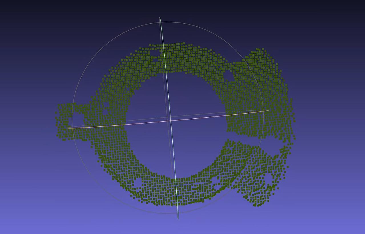
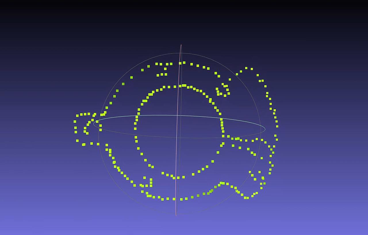
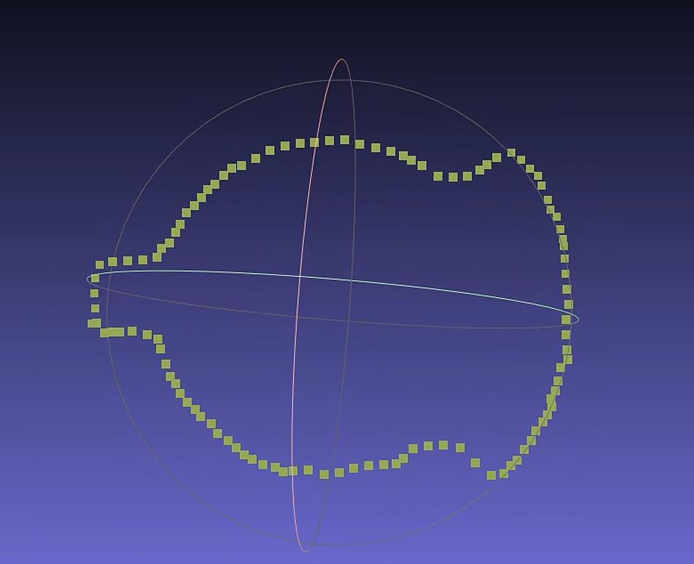
2.1.4 Point Cloud Contour Extraction
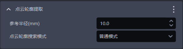
- Function
Extract the workpiece contour from the instance Point Cloud
- Usage Scenario
When 2.2.4 **Enable Contour Mode ** is used, Point Cloud Contour Extraction should also be checked
- Parameter Description
| Parameter Name | Description | Default Value | Value Range | Unit | Parameter Adjustment Suggestion |
|---|---|---|---|---|---|
| Reference Radius (mm) | Search radius for extracting the contour from the instance Point Cloud | 10 | [0.1,10000000000] | mm | The reference radius is recommended to be set to 1/2 of the downsampling point spacing in 2.1.2Point Cloud Downsampling, and it must be greater than the Point Cloud spacing |
| Point Cloud Contour Search Mode | Mode for searching the Point Cloud contour | Normal Mode | Normal Mode; Plane Mode | / | Generally choose Normal Mode; for planar workpieces choose Plane Mode |
- Example
2.1.5 Filter Point Cloud Based on HSV (Hue, Saturation, Value)

- Function
Filter the Point Cloud based on hue, saturation, and value in the Point Cloud image, and screen out Point Cloud areas matching the target range
- Parameter Description
| Parameter Name | Description | Default Value | Value Range |
|---|---|---|---|
| Filter Depth by HSV - Maximum Color Range Value | Maximum color value for filtering the Point Cloud | [0.9,0.9,0.9] | [[0,0,0],[1,1,1]] |
| Filter Depth by HSV - Minimum Color Range Value | Minimum color value for filtering the Point Cloud | [0.0,0.0,0.0] | [[0,0,0],[1,1,1]] |
- Example
2.1.6 Filter Point Cloud Based on Three-Channel Color

- Function
Filter the Point Cloud based on three-channel color and screen out Point Cloud areas matching the target range
- Parameter Description
| Parameter Name | Description | Default Value | Value Range |
|---|---|---|---|
| Filter Point Cloud by Three-Channel Color - Maximum Color Value | Maximum color value for filtering the Point Cloud | [0.9,0.9,0.9] | [[0,0,0],[1,1,1]] |
| Filter Depth by Three-Channel Color - Minimum Color Value | Minimum color value for filtering the Point Cloud | [0.0,0.0,0.0] | [[0,0,0],[1,1,1]] |
- Example
2.1.7 Select Point Clouds Within the ROI Area
- Function
Select Point Clouds within the ROI 3D area from the instance Point Cloud. Default function cannot be deleted
- Example
2.1.8 Remove Points Whose Normals Exceed the Angle Threshold

- Function
Remove Point Clouds whose angle between the Normal and the axis direction of the standard Normal is greater than the Normal angle threshold
- Usage Scenario
Planar workpiece loading and unloading (materials isolated from each other)
- Parameter Description
| Parameter Name | Description | Default Value | Value Range | Unit |
|---|---|---|---|---|
| Angle Threshold | Point Clouds greater than this angle threshold are considered different instances | 15 | [-360, 360] | |
| Standard Normal Axis Direction | The angle formed between the Normal of the Point Cloud and the axis direction of the standard Normal | Z Axis | X/Y/Z Axis | / |
| Whether to Use the ROI Coordinate System | If checked, calculate the angle between the Normal and the axes of the ROI coordinate system; if unchecked, calculate the angle between the Normal and the axes of the Camera coordinate system | Unchecked | / | / |
- Parameter Adjustment
2.1.9 Point Cloud Plane Segmentation
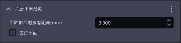
- Function
Retain or remove the plane with the largest number of Point Clouds in the instance Point Cloud
- Usage Scenario
There is a noisy plane in the instance Point Cloud
- Parameter Description
| Parameter | Description | Default Value | Value Range | Unit | Parameter Adjustment Suggestion |
|---|---|---|---|---|---|
| Reference Distance for Plane Fitting (mm) | If the distance from a point to the plane is lower than the reference distance, it is considered a point within the plane; otherwise, it is considered a point outside the plane | 3 | [0.001,10000] | mm | Generally unchanged |
| Remove Plane | If checked, remove the plane with the largest number of Point Clouds; if unchecked, retain the plane with the largest number of Point Clouds | Unchecked | / | / | If the plane with the largest number of Point Clouds is the workpiece, retain the plane and leave it unchecked; if the plane with the largest number of Point Clouds is noise, remove the plane and check it |
- Example
2.1.10 Remove Outlier Points from the Point Cloud
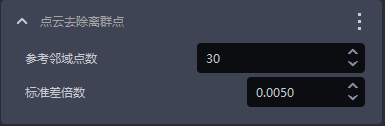
- Function
Identify and remove outlier noise points in the Point Cloud to improve Point Cloud quality
- Usage Scenario
The instance Point Cloud contains many outlier noise points. This is a default function for planar workpiece loading and unloading (materials isolated from each other) and cannot be deleted.
- Parameter Description
| Parameter Name | Description | Default Value | Value Range |
|---|---|---|---|
| Reference Neighboring Point Count | The number of neighboring points for each point in the Point Cloud, that is, the neighborhood size. For dense Point Clouds, even a small neighborhood is enough to reflect workpiece features, so a smaller value can be used; for sparse Point Clouds, a larger neighborhood is required to reflect workpiece features, so a larger value should be used. | 30 | [1, 10000000] |
| Standard Deviation Multiplier | Used to identify outlier noise points. If the deviation of a point's coordinates from the coordinate average of the instance Point Cloud exceeds the standard deviation multiplier, the point is considered an outlier. The smaller the value, the more points are considered outliers and the more outliers are removed, but it may cause misjudgment and remove important workpiece features; the larger the value, the fewer points are considered outliers and the fewer outliers are removed, but some outliers may be retained and affect workpiece recognition accuracy. | 0.005 | [0.0001, 2] |
- Parameter Adjustment
Generally unchanged. If the Point Cloud becomes too sparse after Remove Outlier Points from the Point Cloud, increase the standard deviation multiplier
- Example
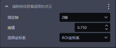
2.1.11 Filter Out Point Clouds Whose Object Distance Exceeds the Limit
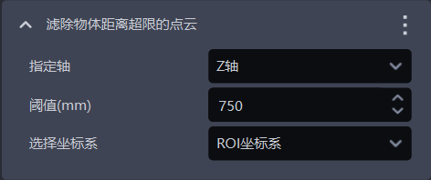
- Function
Filter out Point Clouds in the specified direction, remove noise points, and improve image recognition accuracy
- Parameter Description
| Parameter | Description | Default Value | Parameter Range | Unit | Parameter Adjustment Suggestion |
|---|---|---|---|---|---|
| Specified Axis | Specified axis of the Point Cloud, used to filter out Point Clouds in the specified direction | Z Axis | X/Y/Z Axis | / | Specified Axis generally does not need to be changed |
| Threshold (mm) | Along the specified axis direction, if the distance between the lower-layer Point Cloud and the workpiece Point Cloud is greater than this threshold, the lower-layer Point Cloud will be filtered out; if the distance between the lower-layer Point Cloud and the workpiece Point Cloud is less than this threshold, the lower-layer Point Cloud will be retained | 750 | [0, 1000] | mm | Adjust Threshold according to the actual scene. The larger the Threshold, the fewer Point Clouds are filtered out; the smaller the Threshold, the more Point Clouds are filtered out |
| Select Coordinate System | Filter out Point Clouds in the selected coordinate system | ROI Coordinate System | Camera Coordinate System; ROI Coordinate System; Object Coordinate System | / |
- Example
2.1.12 Point Cloud Downsampling (Workpiece Point Cloud)
- Feature Overview
The scene Point Cloud used for fine matching can be downsampled (different from coarse matching). It is recommended to add it and move it to the top of the preprocessing functions when using it.
- Usage Scenario
Use fine matching, but the time cost is high and does not meet the overall Takt Time requirements.
- Parameter Description
| Parameter | Description | Default Value | Value Range | Unit |
|---|---|---|---|---|
| Downsampling Point Spacing (mm) | Sample the Point Cloud according to the specified point spacing to reduce the number of Point Clouds and improve vision calculation speed | 1 | [0.1,1000] | mm |
The larger the value, the larger the downsampling point spacing, the fewer Point Clouds after downsampling, and the faster the vision calculation speed, but the accuracy may decrease;
The smaller the value, the smaller the downsampling point spacing, the more Point Clouds after downsampling, and the slower the vision calculation speed, but the accuracy may improve.
After running, the Point Cloud Template in the workpiece configuration can be updated to the downsampled workpiece Point Cloud in the historical data to appropriately reduce coarse matching time consumption.
- Example
2.1.13 [Advanced] Read Instance Point Cloud
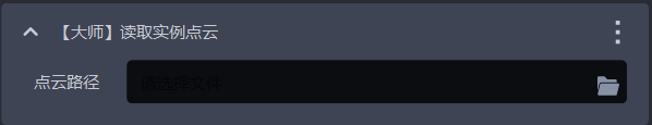
- Feature Overview
Read the instance Point Cloud
- Usage Scenario
Planar workpiece scenario
- Parameter Description
| Parameter | Description | Default Value | Value Range | Unit |
|---|---|---|---|---|
| Point Cloud Path | Workpiece Point Cloud path. If not filled in, the Point Cloud uploaded on the workpiece page will be used | / | / | / |
2.1.14 Optimize Mask Based on Point Cloud
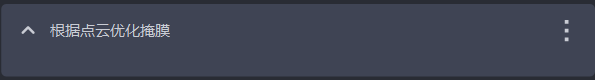
- Function
Based on the Point Cloud within ROI 3D, remove the Point Cloud in the Mask that is not within ROI 3D to improve Mask accuracy
2.2 Point Cloud Matching Pose Estimation
2.2.1 Model Point Cloud Downsampling Size (mm)
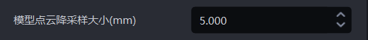
- Function
Before coarse matching, the sampling box size when downsampling the template Point Cloud
- Usage Scenario
Planar workpiece ordered loading and unloading, planar workpiece unordered picking, planar workpiece positioning assembly, and planar workpiece positioning assembly (matching only)
- Parameter Description
Default value: 5
Value range: [0.001, 500]
Unit: mm
Parameter Adjustment
- The larger the size, the fewer points retained during downsampling, and the fewer points in the downsampled template Point Cloud
It is recommended that the number of points in the downsampled template Point Cloud be less than 300
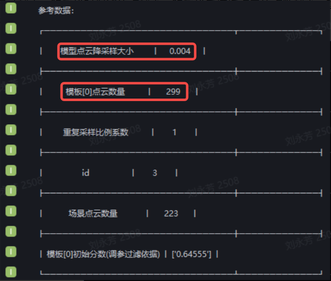
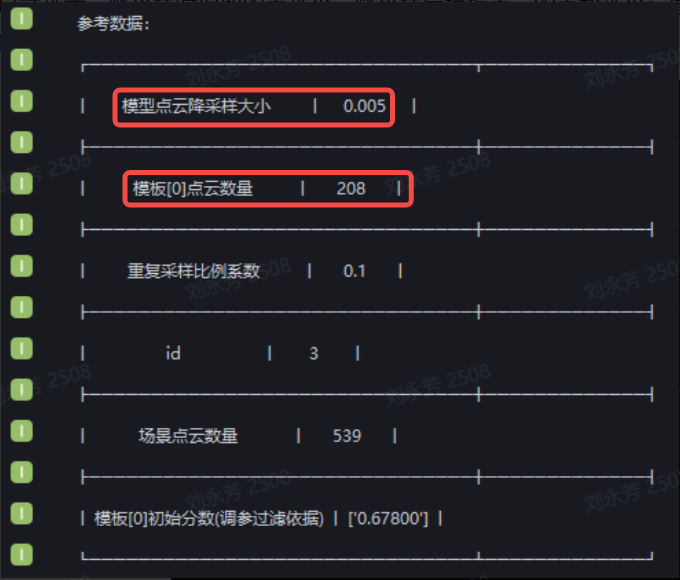
- If the log reports the error "The model point count is greater than 1000. Please appropriately increase the model Point Cloud downsampling size parameter in 3D Matching", Model Point Cloud Downsampling Size should be increased to reduce the number of points in the downsampled template Point Cloud;


2.2.2 Repeat Sampling Ratio Coefficient
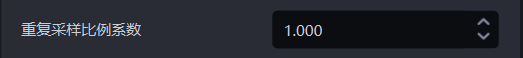
- Function
The repetition degree of sampling point pairs in the processed template Point Cloud
- Usage Scenario
Planar workpiece ordered loading and unloading, planar workpiece unordered picking, planar workpiece positioning assembly, and planar workpiece positioning assembly (matching only)
- Parameter Description
Default value: 1
Value range: [0.1,1]
Parameter Adjustment
- The larger the value, the higher the success rate of coarse matching, but the more time coarse matching takes
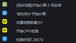
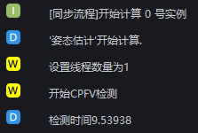
- If the log reports the error "Please adjust parameters such as the downsampling point spacing parameter, model Point Cloud downsampling size, and Repeat Sampling Ratio Coefficient in 3D Matching. For details, refer to the CPFV parameter adjustment guide", Repeat Sampling Ratio Coefficient should be increased. It is generally recommended to start adjusting from 1. A value of 1 is the slowest but has the highest fine matching success rate, while 0.1 is the fastest but has the lowest fine matching success rate.

- If the log reports the error "Timeout warning triggered. Please refer to the CPFV parameter adjustment guide to modify the parameters", Repeat Sampling Ratio Coefficient should be decreased

2.2.3 Pose Angle Prior
- Function
Before coarse matching, provide the approximate orientation of the workpiece in the ROI coordinate system in advance to improve the accuracy of coarse matching
- Usage Scenario
Planar workpiece ordered loading and unloading, planar workpiece positioning assembly, and planar workpiece positioning assembly (matching only) scenarios. Because of the rotational symmetry of planar workpieces, the effects of coarse matching and fine matching are poor
Not applicable to planar workpiece unordered picking scenarios
- Parameter Description
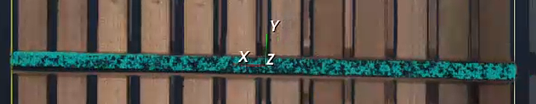
The value has 4 digits. The first 3 digits indicate the direction of the workpiece, and the 4th digit uses 0/1/2 to represent the X/Y/Z axis of the ROI coordinate system respectively
Default value: []
Value range: [1,0,0,0] indicates the positive X-axis direction, and [-1,0,0,0] indicates the negative X-axis direction;
[0,1,0,1] indicates the positive Y-axis direction, and [0,-1,0,1] indicates the negative Y-axis direction;
[0,0,1,2] indicates the positive Z-axis direction, and [0,0,-1,2] indicates the negative Z-axis direction.
Format: [[1,0,0,0]], with two square brackets; the directions of the XYZ axes can be combined, such as [[1,0,0,0],[0,1,0,1],[0,0,1,2]], which indicates the positive X-axis direction, positive Y-axis direction, and positive Z-axis direction
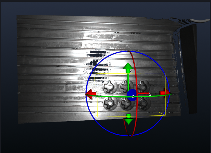
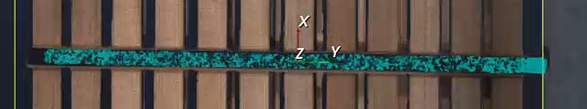
- Example
Determine according to the orientation of the planar workpiece. As shown in the figure below, the planar workpiece faces the positive X-axis direction, so Pose Angle Prior can be set to [[1,0,0,0]]
2.2.4 Enable Contour Mode

- Function
Extract the contour of the instance Point Cloud, and use the contour of the downsampled template Point Cloud and the contour of the downsampled instance Point Cloud for coarse matching
- Usage Scenario
Planar workpiece ordered loading and unloading, planar workpiece unordered picking, planar workpiece positioning assembly, and planar workpiece positioning assembly (matching only) scenarios. Because the contour features of the workpiece are obvious, using contour mode can avoid poor coarse matching caused by the easy slipping of planar workpieces
When using contour mode, 2.1.4 Point Cloud Contour Extraction should also be checked to extract contours from the instance Point Cloud
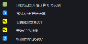
Example
- When contour mode is used, the log will display the message "Using contour mode, contour point count found"
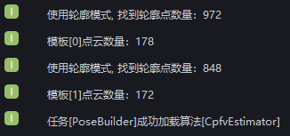
Contour Mode

- Function
Extract the contour of the template Point Cloud, and use the contour of the downsampled template Point Cloud and the contour of the downsampled instance Point Cloud for coarse matching
- Usage Scenario
Planar workpiece ordered loading and unloading, planar workpiece unordered picking, planar workpiece positioning assembly, and planar workpiece positioning assembly (matching only). If the coarse matching effect is poor, check this function to use contour Point Clouds for coarse matching again
- Parameter Adjustment
Normal Mode: default value
Plane Mode: for planar workpieces, choose Plane Mode
- Example
2.2.5 Coarse Registration Contour Search Radius

- Function
Use the contour of the downsampled template Point Cloud and the contour of the downsampled instance Point Cloud for coarse matching, and extract the search radius of the contour Point Cloud in the template Point Cloud and instance Point Cloud
- Usage Scenario
Planar workpiece ordered loading and unloading, planar workpiece unordered picking, planar workpiece positioning assembly, and planar workpiece positioning assembly (matching only)
- Parameter Description
Default value: 0.005
Value range: [0.0001,0.5]
Unit: m
2.2.6 Object Pose Correction
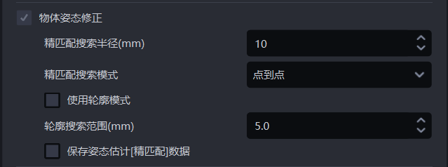
Fine Matching Search Radius (mm)

- Function
During fine matching, the template Point Cloud is matched with the instance Point Cloud, and each point in the template Point Cloud needs to search for the nearest point in the instance Point Cloud. The fine matching search radius represents both the search radius in the instance Point Cloud and the distance threshold between each point in the template Point Cloud and the nearest point in the instance Point Cloud. If the distance between a point and its nearest point is less than the fine matching search radius, the two points are considered matchable; otherwise, they are considered unmatched.
- Usage Scenario
Planar workpiece ordered loading and unloading, planar workpiece unordered picking, planar workpiece positioning assembly scenarios
- Parameter Description
Default value: 10
Value range: [1, 500]
Unit: mm
- Parameter Adjustment
Usually unchanged
Fine Matching Search Mode

- Function
The method for the template Point Cloud to retrieve the nearest point in the instance Point Cloud during fine matching
- Usage Scenario
If the fine matching effect between the template Point Cloud and the instance Point Cloud is poor, this function should be adjusted
- Parameter Description
| Parameter | Description |
|---|---|
| Point to Point | Each point in the template Point Cloud searches for the nearest point in the instance Point Cloud (the point with the shortest straight-line distance within the search radius), which is suitable for all workpieces |
| Point to Plane | Each point in the template Point Cloud searches for the nearest point in the instance Point Cloud along its Normal, which is suitable for workpieces with obvious geometric features |
| Combination of Point to Point and Point to Plane | First use point-to-point mode to optimize the workpiece pose in the instance Point Cloud, then use point-to-plane mode to optimize the workpiece pose in the instance Point Cloud, which is suitable for workpieces with obvious geometric features
|
Use Contour Mode
- Function
Extract the contour Point Clouds in the template Point Cloud and instance Point Cloud for coarse matching
- Usage Scenario
For planar workpiece ordered loading and unloading, planar workpiece unordered picking, and planar workpiece positioning assembly scenarios, if the result of coarse matching using key points is poor, this function should be checked to use contour Point Clouds for coarse matching again
- Parameter Adjustment
The result of coarse matching affects the result of fine matching. If the fine matching result is poor, you can check Use Contour Mode
Contour Search Range (mm)

- Function
The search radius for extracting contour Point Clouds in the template Point Cloud and instance Point Cloud
- Usage Scenario
General workpiece ordered loading and unloading, general workpiece unordered picking, and general workpiece positioning assembly scenarios
- Parameter Description
Default value: 5
Value range: [0.1, 500]
Unit: mm
- Parameter Adjustment
If the value is small, the search radius for contour Point Clouds is small, which is suitable for extracting fine workpiece contours, but the extracted contours may contain outlier noise points;
If the value is large, the search radius for contour Point Clouds is large, which is suitable for extracting wider workpiece contours, but the extracted contours may ignore some detailed features.
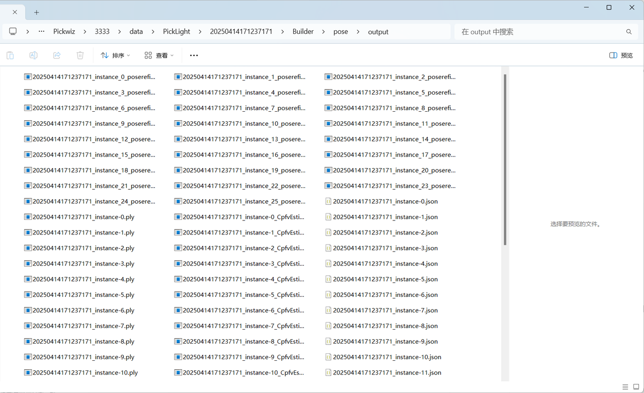
Save Pose Estimation [Fine Matching] Data
- Function
If checked, save fine matching data
- Usage Scenario
Planar workpiece ordered loading and unloading, planar workpiece unordered picking, planar workpiece positioning assembly, and planar workpiece positioning assembly (matching only)
- Example
The fine matching data is saved in the \ProjectFolder\data\PickLight\HistoricalDataTimestamp\Builder\pose\output folder.
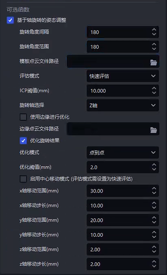
2.2.7 Pose Adjustment Based on Axis Rotation
- Function
Rotate and translate the instance Point Cloud around the given axis based on the first Pick Point of the workpiece, calculate the matching score between the instance Point Cloud and the template Point Cloud after each rotation and translation, and select the instance Point Cloud with the highest matching score as the final pose of the rotationally symmetric workpiece.
- Usage Scenario
When the instance Point Cloud of a rotationally symmetric workpiece is matched with the template Point Cloud, deviation occurs and a certain angle of rotation is required for a complete match
Cannot be used together with recognition type, positive/negative recognition (through the Point Cloud Template), or local feature recognition in the function options
- Parameter Description
| Parameter | Description | Default Value | Parameter Range | Parameter Adjustment Suggestion |
|---|---|---|---|---|
| Rotation Angle Interval | Rotate the instance Point Cloud at equal angle intervals. The angle difference between two adjacent rotations. For example, if the first rotation is 30°, the second rotation is 60°, and the third rotation is 90°, then the rotation angle interval is 30°. | 5 | \[1, 180\] | If the workpiece has many features and matching is difficult and high-precision matching is desired, a smaller angle interval can be set for more matches, but the computation will increase. If the workpiece shape is simple and has fewer features, a larger angle interval can be set to improve calculation efficiency. |
| Rotation Angle Range | The angular range through which the instance Point Cloud can rotate from its initial state. | 90 | \[1, 180\] |
|
| Template Point Cloud File Path | Upload the template Point Cloud file of the workpiece. If not uploaded, use the Point Cloud Template uploaded on the workpiece page | / | / | |
| Evaluation Mode | Evaluate the quality of the matching result from different perspectives | Iso-target | Iso-target;Iso-source;Average;Strict;Loose;Fast |
|
| ICP Threshold | The criterion for determining whether registration is successful. If the matching result error is less than this threshold, matching is successful; if the matching result error is greater than this threshold, matching is unsuccessful | 0.005 | \[0.000001, 1\] | Generally unchanged. If the actual scene has high requirements for matching accuracy, reduce this threshold; if the actual scene has high requirements for matching speed and low requirements for accuracy, increase this threshold. If the workpiece Point Cloud quality is good, the threshold can be reduced; if the workpiece Point Cloud quality is poor, the threshold can be increased. |
| Rotation Axis Selection | The instance Point Cloud rotates around this axis | Z Axis | X/Y/Z Axis | Generally unchanged. If a certain axis of a rotationally symmetric workpiece is important for recognizing the workpiece pose, the rotation axis can be set to that feature axis |
| Save Visualized Data | Whether to save visualized data | Unchecked | / | |
| Use Edges for Optimization | Use the edge contour of the workpiece to optimize matching, reduce matching result errors, and make the matching between the instance Point Cloud and the template Point Cloud finer | Unchecked | / | If the edge contour of the workpiece has unique geometric features, check this function to improve matching accuracy. For example, for workpieces with complex shapes and large differences in edge contours, the Point Cloud of the edge contour can be used to identify the workpiece pose more accurately. |
| Edge Point Cloud File Path | Upload the edge Point Cloud file of the workpiece. If not uploaded, extract the edge Point Cloud from the Point Cloud Template uploaded on the workpiece page | / | / | |
| Optimize Rotation Result | After the best pose is found during matching, optimize it again to reduce matching result errors and make the matching between the instance Point Cloud and the template Point Cloud finer | Checked | / | Checked by default to improve matching accuracy, and generally unchanged |
| Optimization Mode | Mode for optimizing matching results | Point | Point;Plane;Full |
|
| Optimization Threshold | The criterion for determining whether registration has reached the expected precision during optimization. If the registration error is less than this threshold, optimization succeeds; if the registration error is greater than this threshold, optimization fails and iteration needs to continue. | 0.002 | \[0.0001, 1\] | Generally unchanged. For scenes requiring high registration precision, reduce this threshold; for scenes requiring low registration precision, increase this threshold. |
| Enable Center Movement Mode | If enabled, translation mode will be added at the same time, superimposing translation while rotating the instance Point Cloud | Unchecked |
| |
| x Axis Movement Range | Movement range of the center movement mode along the x axis of the Pick Point (mm) | 0 | \[0,100\] |
|
| x Axis Movement Step Size | Step size of the center movement mode along the x axis of the Pick Point (mm) | 2 | \[0.01,10\] | The step size should be set reasonably according to the offset situation and accuracy. Setting too small a step size will lead to a significant increase in Takt Time |
| y Axis Movement Range | Movement range of the center movement mode along the y axis of the Pick Point (mm) | 0 | \[0,100\] |
|
| y Axis Movement Step Size | Step size of the center movement mode along the y axis of the Pick Point (mm) | 2 | \[0.01,10\] | The step size should be set reasonably according to the offset situation and accuracy. Setting too small a step size will lead to a significant increase in Takt Time |
| z Axis Movement Range | Movement range of the center movement mode along the z axis of the Pick Point (mm) | 0 | \[0,100\] |
|
| z Axis Movement Step Size | Step size of the center movement mode along the z axis of the Pick Point (mm) | 2 | \[0.01,10\] | The step size should be set reasonably according to the offset situation and accuracy. Setting too small a step size will lead to a significant increase in Takt Time |
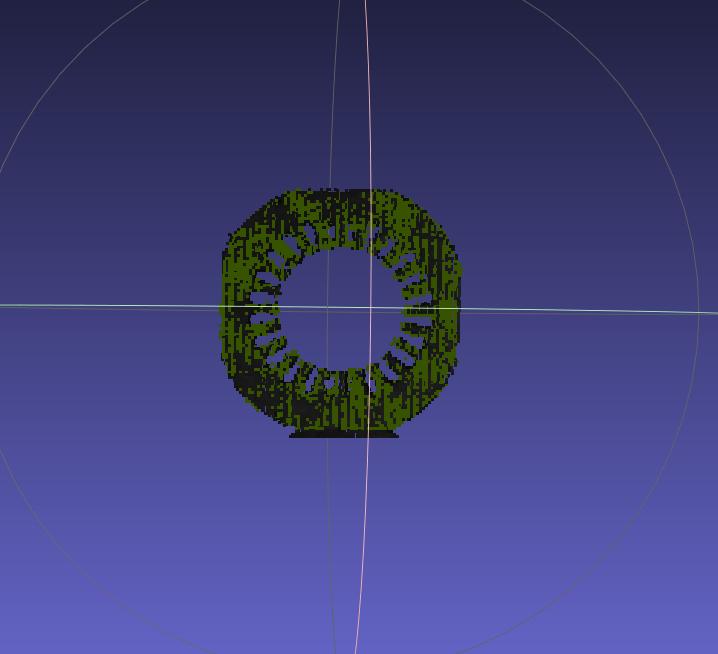
- Example
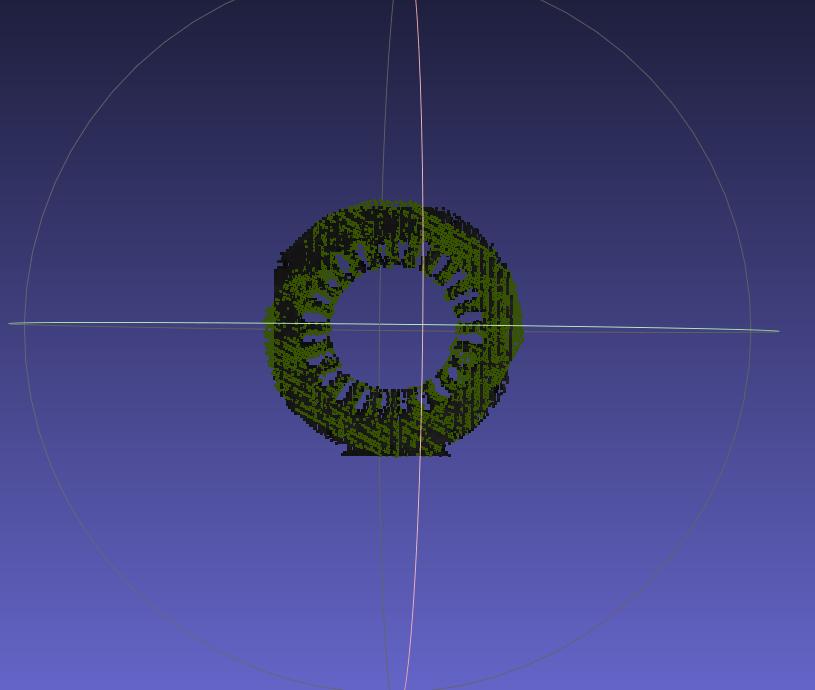
Axial Matching Offset
After Enabling Center Movement Mode
- Description of the Number of Poses Evaluated by Pose Adjustment Based on Axis Rotation
Total number of pose calculations = number of point positions for x-axis movement * number of point positions for y-axis movement * number of point positions for z axis movement * number of angular positions
Excessively large movement ranges or excessively small step sizes will increase the total number of poses that need to be evaluated and lengthen the Takt Time. The range and step-size parameters should be set reasonably
2.3 Empty ROI Determination
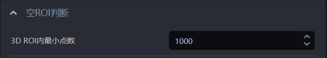
- Function
Determine whether there are any workpieces (Point Clouds) remaining in ROI 3D. If the number of 3D points in ROI 3D is less than this value, it indicates that no workpiece Point Cloud remains, and no Point Cloud is returned
- Parameter Description
Default value: 1000
Value range: [0, 100000]
- Usage Process
Set the minimum point count threshold for ROI 3D. If it is less than this threshold, the workpiece Point Cloud in ROI 3D is insufficient, and it is therefore determined that there is no workpiece in ROI 3D;
Add a vision status code in the Robot configuration to facilitate subsequent Robot signal processing.