Training Imaging Models with One-Click Connection
An imaging model is a Deep Learning model. It takes the 2D images captured by the left and right cameras of a stereo KINGFISHER camera, along with the camera Intrinsic Parameters, analyzes the disparity between the two 2D images, and uses triangulation principles and Deep Learning techniques to predict the depth information of each pixel in the scene. It ultimately outputs the scene depth map and Point Cloud data.
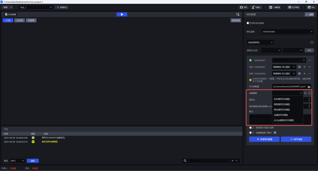
The stereo KINGFISHER camera has five built-in general-purpose imaging models: the general stereo model for depalletizing, the general stereo model for circular surfaces, the general stereo model for cylinders, the stereo model for metal ingots, and the stereo model for reflective metal cylinders. If these five general-purpose models do not meet scene requirements, a scene-specific imaging model should be trained and imported.
If the general-purpose model or a specially trained imaging model of the stereo camera shows issues such as point cloud collapse on site, you can use One-Click Connection to further train and optimize the imaging model.
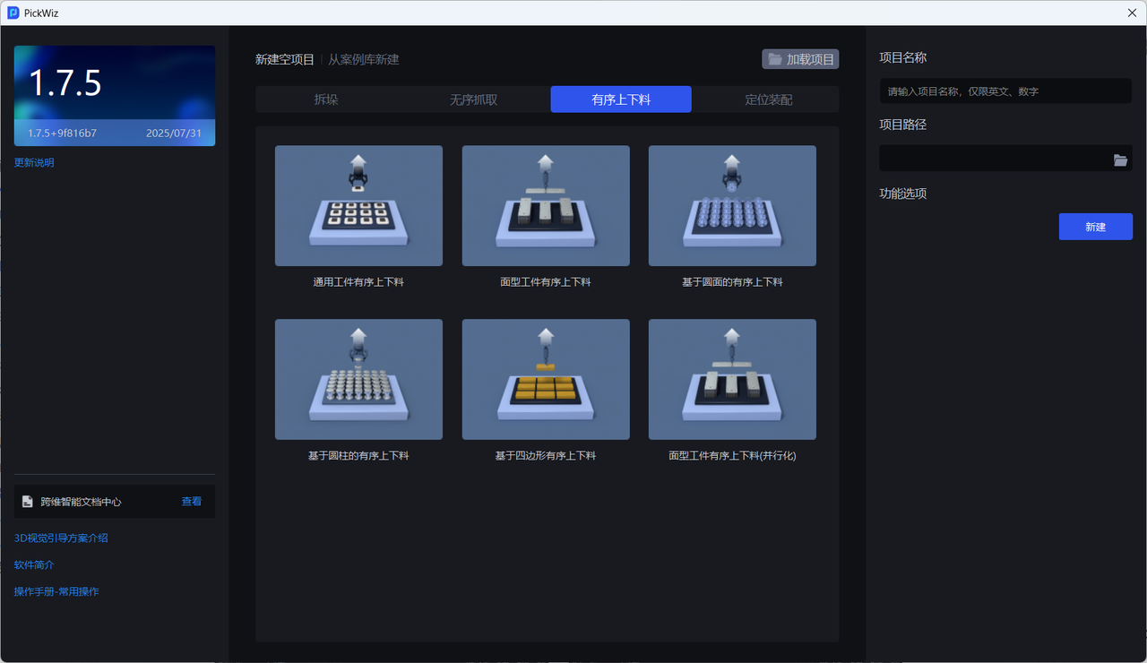
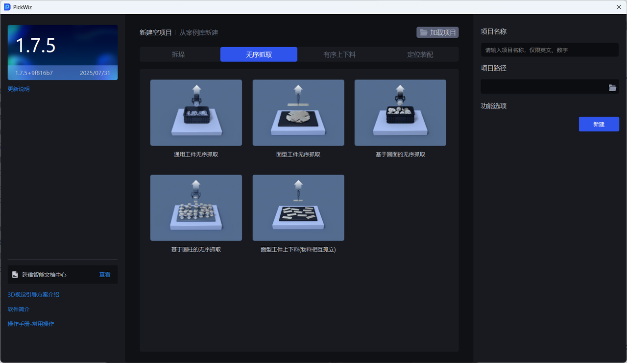
1. Select a Task Scene
The stereo KINGFISHER camera currently supports using One-Click Connection to train imaging models in ordered and unordered scenes, but does not yet support multiple workpiece categories (Function Options-Recognition Type).
2. Configure the Stereo Camera
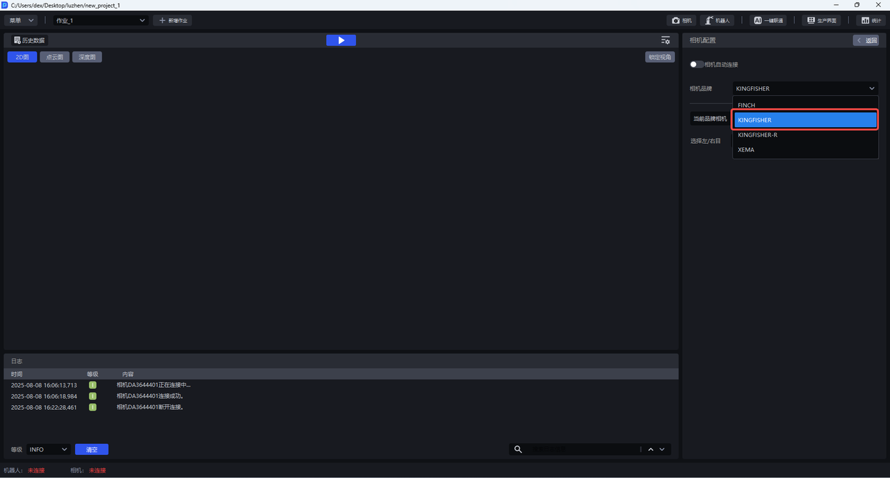
2.1 Connect the Stereo Camera (if available)
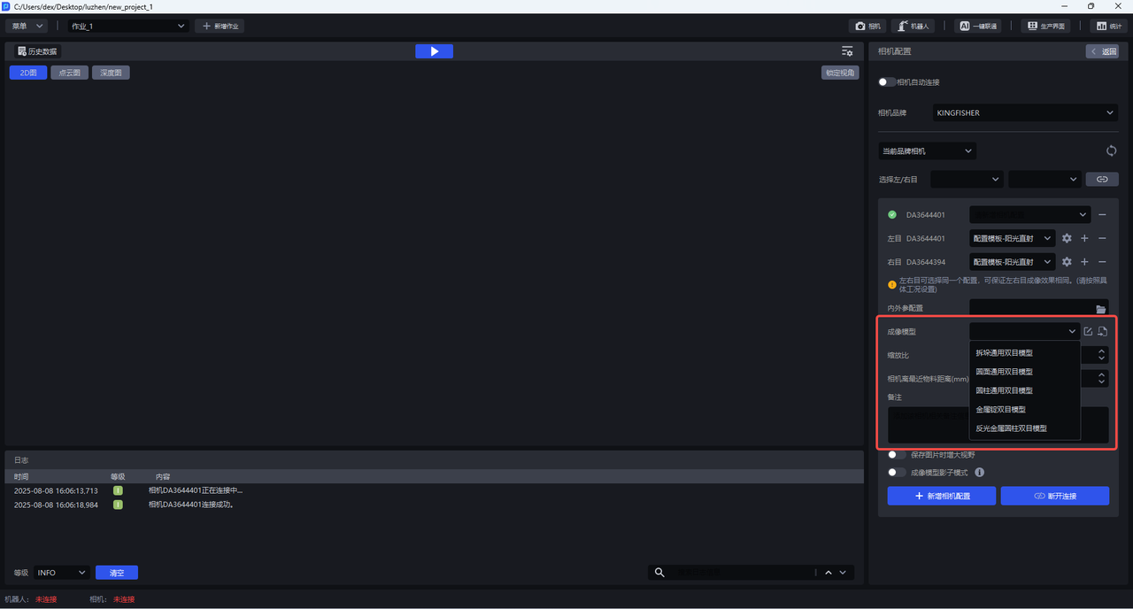
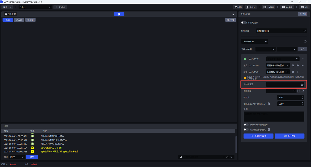
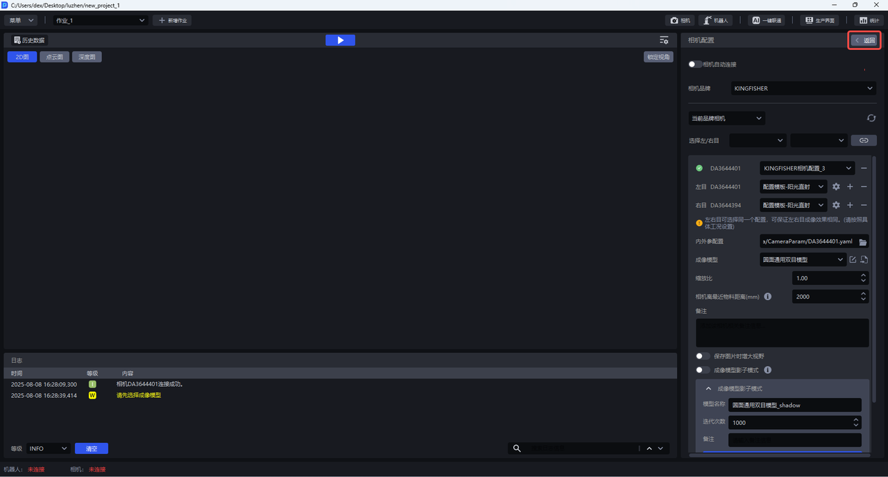
After installing the stereo KINGFISHER camera, connect the stereo camera in PickWiz, set the scale ratio, select the imaging model, and set the minimum distance (adjust according to actual conditions).
(1)Connect the stereo camera
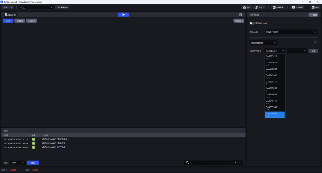
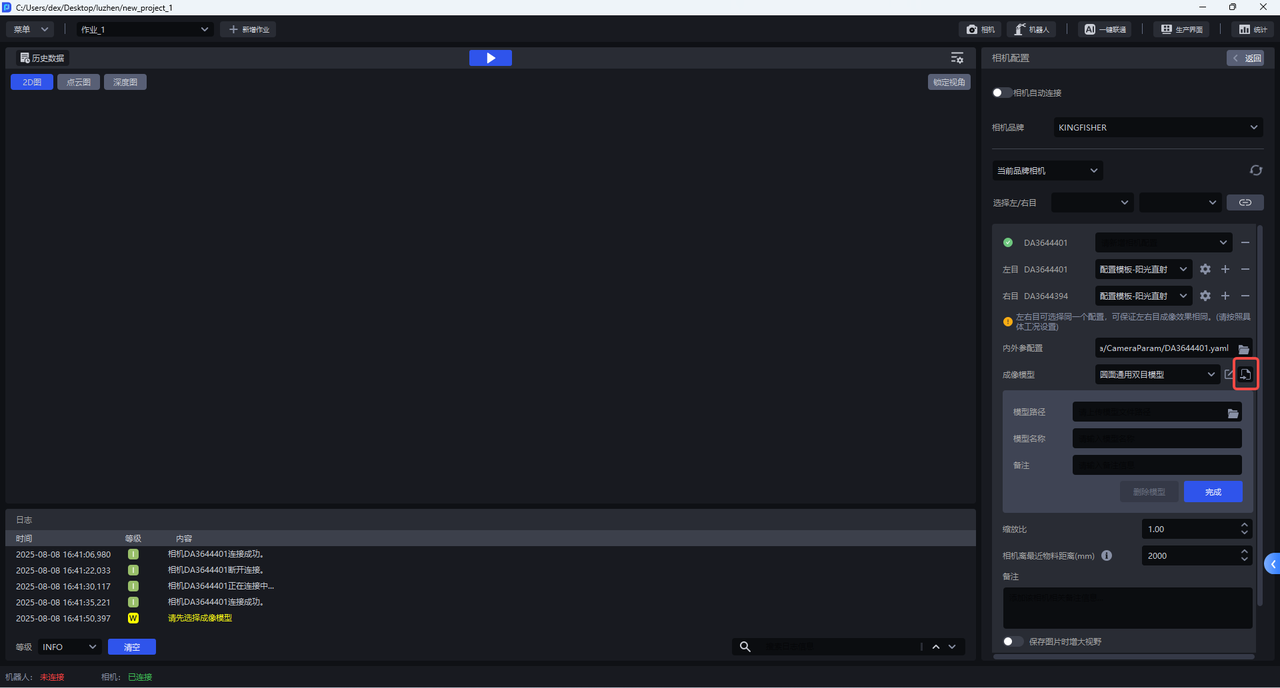
(2)Download the intrinsic and extrinsic parameter configuration files of the stereo camera from KINGFISHER-Camera Calibration Files and import them. These Intrinsic Parameters and Extrinsic Parameters configuration files will be read during imaging model training.
(3)Select a general-purpose model or import a scene-specific trained imaging model. This model is the imaging model to be trained with One-Click Connection.
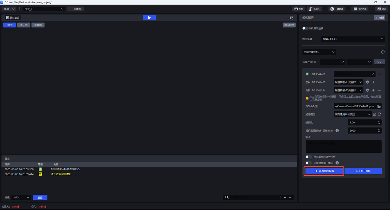
(4)Click +Add Camera Configuration
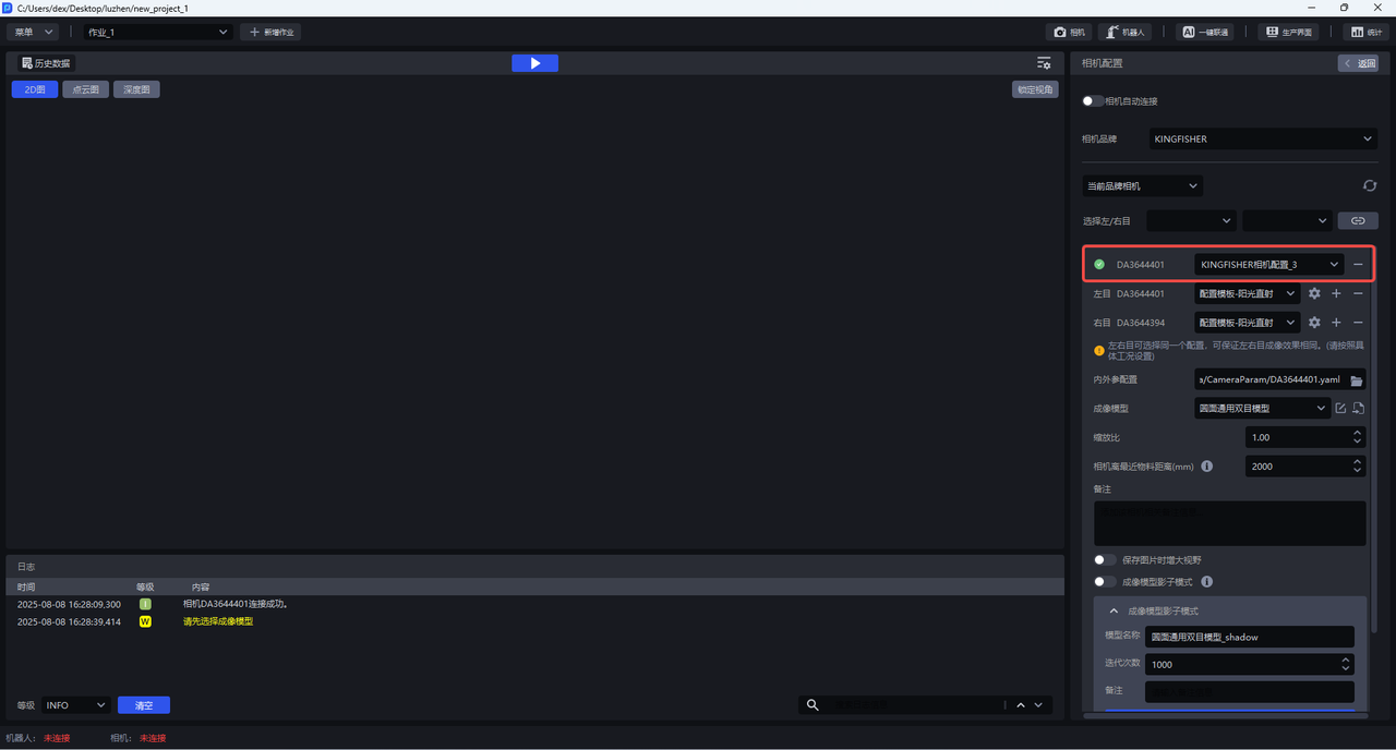
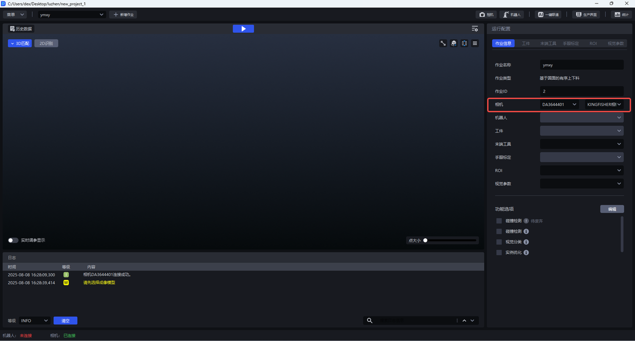
(5)Click Back, then select the newly added camera configuration in task information
2.2 Select the Stereo Camera (when no camera is connected)
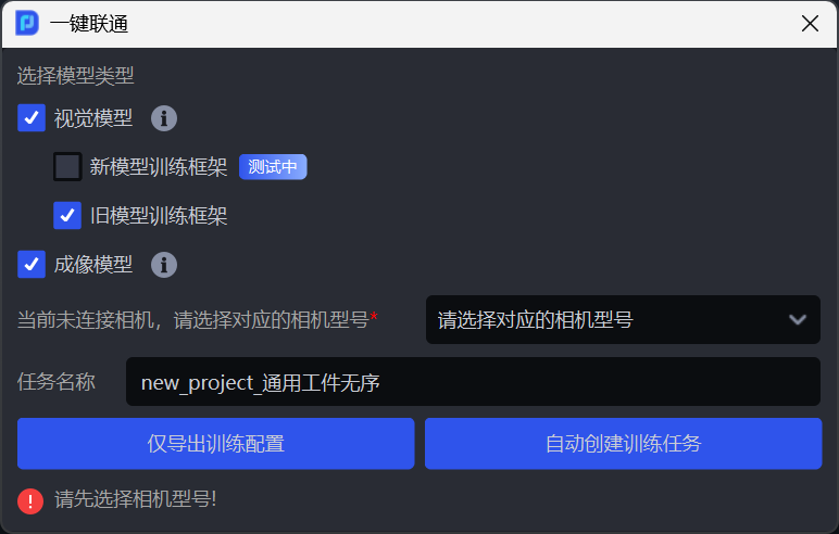
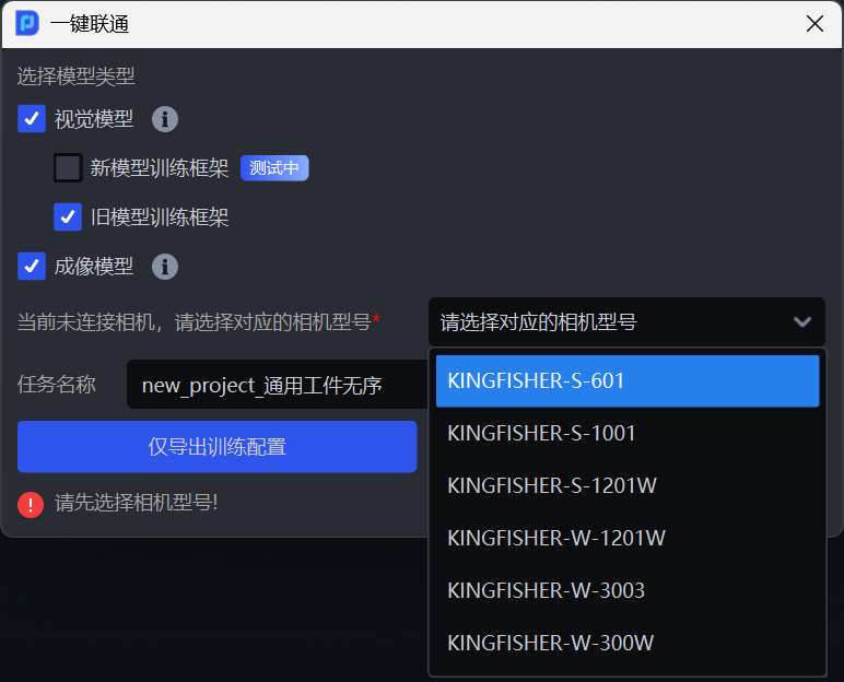
If no camera is connected, after completing 3. Configure Workpieces, 4. Configure ROI, and 5. Configure Scene Objects, when you start One-Click Connection and select the imaging model, the system will prompt that no camera is connected, and you can select the corresponding camera model.
3. Configure Workpieces
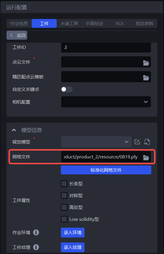
3.1 Mesh File
For general workpieces, surface workpieces, circular-surface workpieces, cylindrical workpieces, and quadrilateral workpieces, training imaging models with One-Click Connection relies on mesh files to render a large number of synthetic images under different viewpoints and lighting conditions, thereby expanding the training data and improving the generalization ability of the imaging model.
Upload the mesh file and click Standardize Mesh File. Currently, only mesh files in ply format are supported.
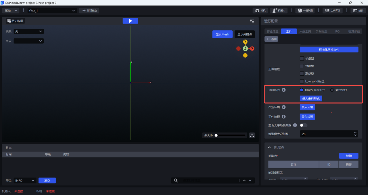
3.2 Feed Arrangement
In ordered loading/unloading scenes, the feed arrangement affects the angle and placement of the workpiece within the camera field of view, so Feed Arrangement must be entered. The Feed Arrangement should include all situations that may occur on site, and the training data generated by One-Click Connection will include synthetic images for various feed arrangements.
There are two types of feed arrangement: “Closely Packed” and “Custom Feed Arrangement.” “Closely Packed” is suitable for scenes where workpieces are fed in order, have consistent poses, and have small spacing. “Custom Feed Arrangement” is suitable for all ordered feeding scenes.
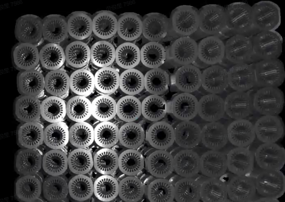
3.2.1 Closely Packed
If the scene involves ordered feeding, consistent poses, and small spacing between workpieces, you can click Close Fit and set the number of workpieces in each row and column. However, the total number of workpieces must be less than 40. If the number of workpieces exceeds 40, you must ensure that the ratio of the configured row/column counts has a common proportional relationship with the actual row/column counts. For example, if the actual feed arrangement has 12 workpieces per row and 8 per column, then the row/column ratio is 12:8, which reduces to 3:2. Therefore, setting 3 per row and 2 per column or 6 per row and 4 per column is acceptable, but 9 per row and 6 per column is not (because it exceeds 40).
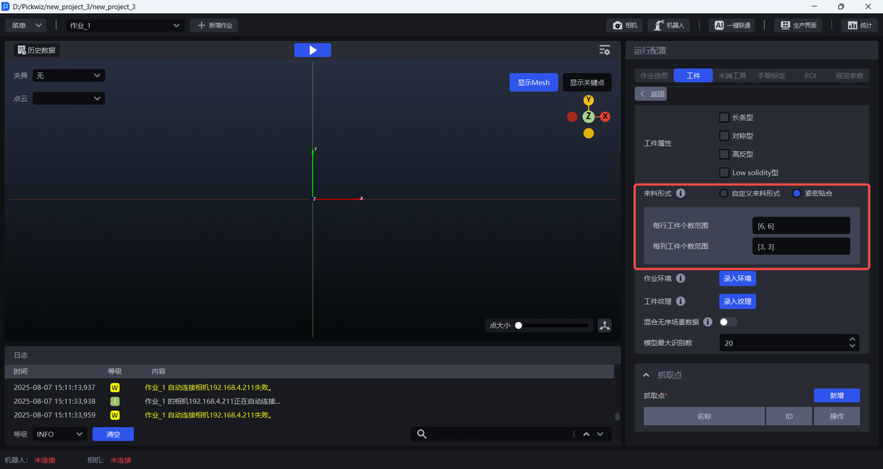
Example:
The feed arrangement of the workpiece is 6 per row and 3 per column, for a total of 18 workpieces. Therefore, the range for the number of workpieces per row can be set directly to [6,8], and the range for the number of workpieces per column can be set to [2,3]
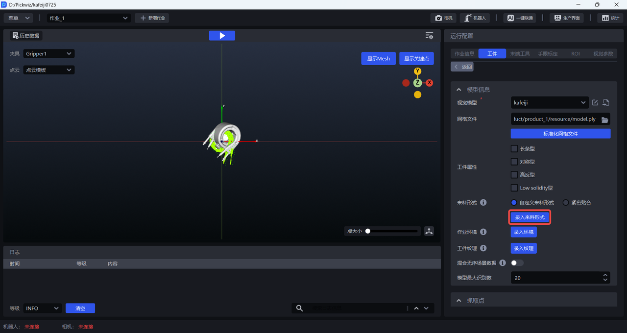
3.2.2 Custom Feed Arrangement
All ordered feeding scenes can use a custom feed arrangement. The steps are as follows:
- Click
Enter Feed Arrangementto open theFeed Arrangement Editor
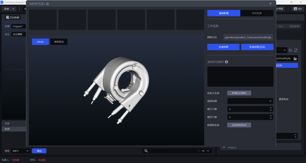
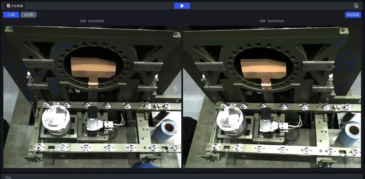
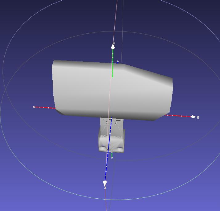
- Rotate the Mesh model to an appropriate pose (the workpiece pose under the camera viewpoint), then click
Generate Snapshot/Generate Snapshots (Front/Back)to generate workpiece snapshots under that pose.Generate Snapshots (Front/Back)generates snapshots from both the front and back viewpoints at the same time, as shown below.
- After generating snapshots, you can click
Add Blank Canvasand drag the snapshots onto the canvas to create the workpiece feed arrangement according to the actual scene, as shown below.
You can also select snapshots, set the number of rows and columns, and then click Generate Feed Arrangement. The system will directly generate the feed arrangement on the canvas according to the selected snapshots and the configured row and column counts, as shown below.
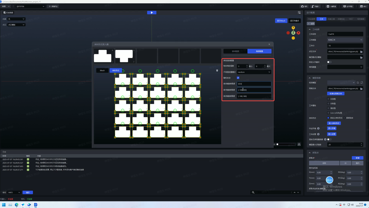
- After entering the feed arrangement, configure the remaining items one by one. After One-Click Connection is triggered, the training for ordered scenes will generate training data based on the entered feed arrangement, as shown below.
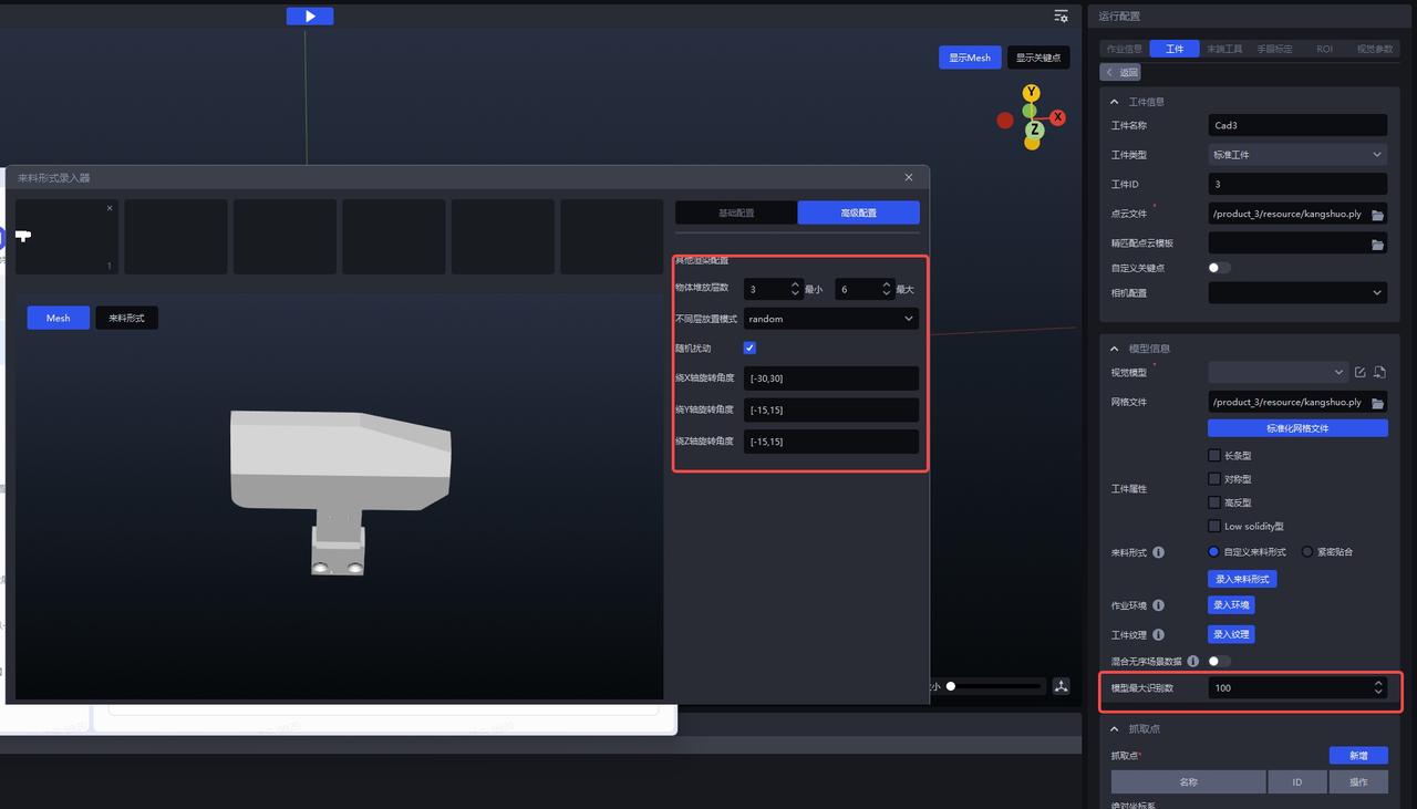
If workpieces are stacked in the actual scene, click
Advanced Configurationto configure the stacking conditions. Set the rotation angles according to the workpiece pose.
Confirm the stacking height
Set the possible viewpoints of the workpiece and configure rotational angles
In Advanced Configuration, you should judge the possible angle deviations of on-site workpieces based on the CAD model and snapshots. As shown below, if the workpiece is most likely to have an angle deviation around the x-axis on site, the rotation angle around the X-axis should be set larger. At the same time, small disturbances may also occur around the y- and z-axes, so smaller rotation angle values should also be set for the Y-axis to ensure that the specified angles can cover possible on-site scenarios.
| Before Modification (Incorrect) | After Modification | |
|---|---|---|
| pattern | 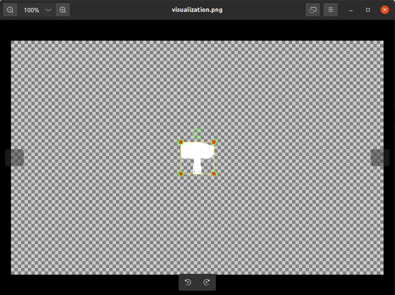 | 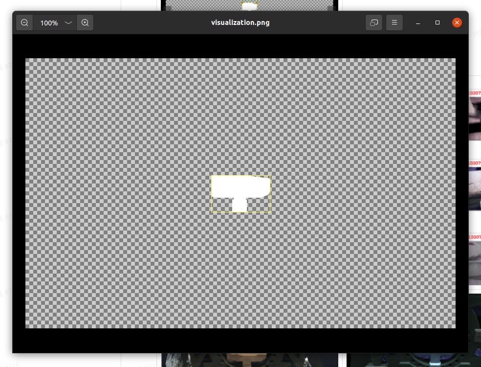 |
| TB | 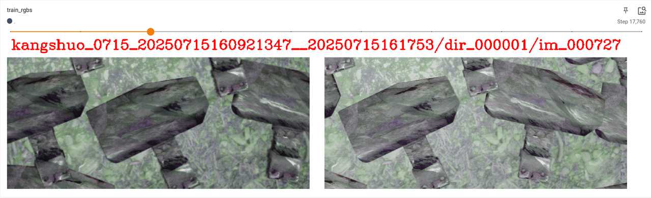 | 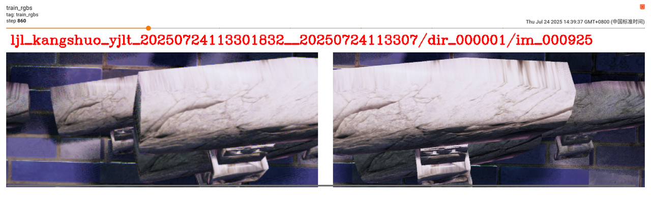 |
| Point Cloud Imaging | 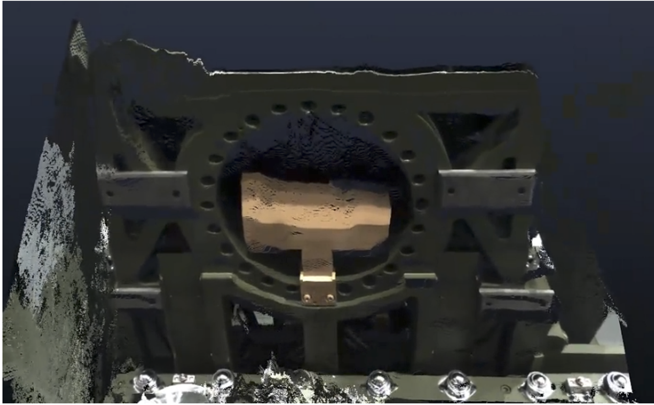 | 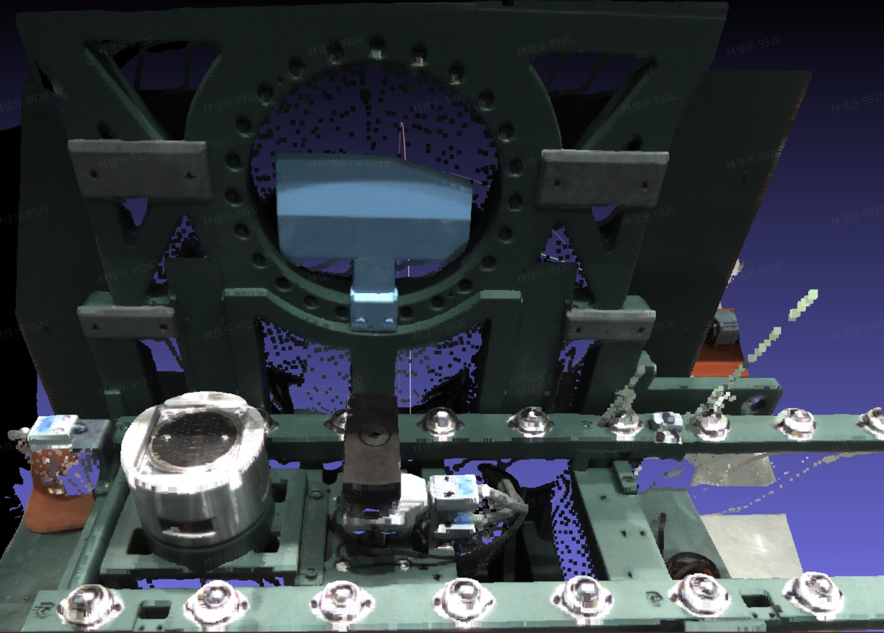 |
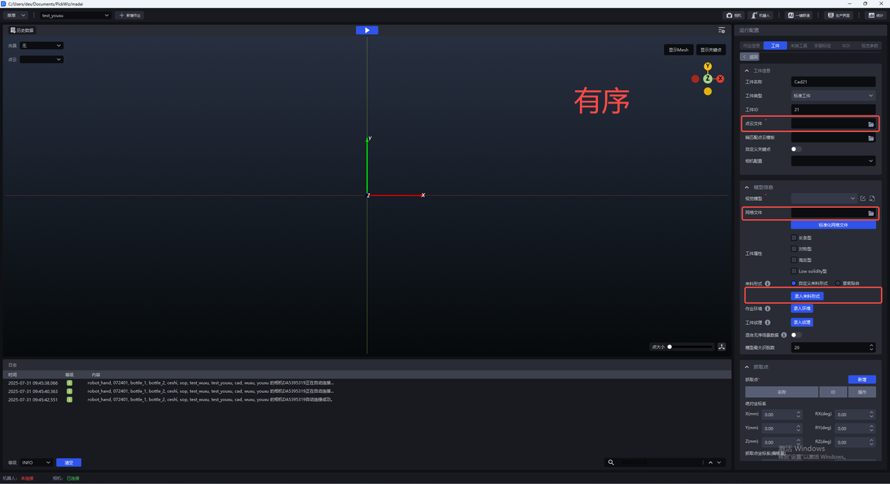
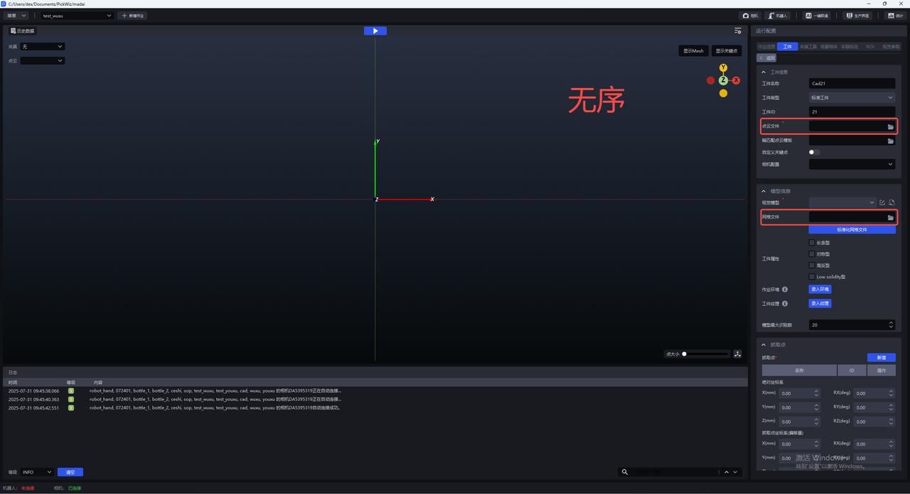
3.3 Check Workpiece Configuration
In ordered loading/unloading scenes, mesh files, Point Cloud files, and feed arrangements must be configured. In unordered picking scenes, mesh files and Point Cloud files must be configured. Please check whether the workpiece configuration is complete. If it is incomplete, an error will occur when One-Click Connection is triggered later.
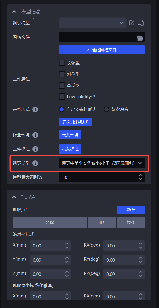
3.4 Field of View Type
In a single-target scenario, the field-of-view type parameter in the workpiece module can be used to specify the actual rendering height for One-Click Connection according to the actual scene conditions.
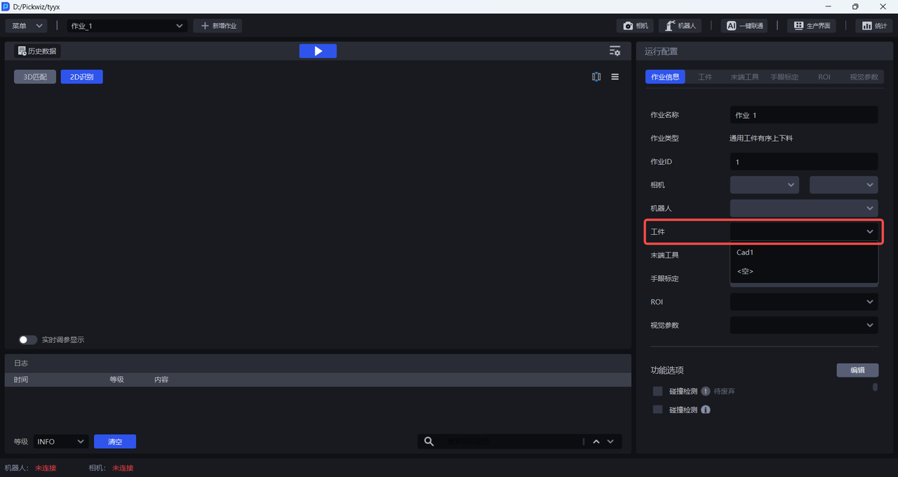
After confirming that everything is correct, select the newly added workpiece configuration in task information.
4. Configure ROI
Please refer to ROI Operation Guide to configure ROI 3D and ROI 2D on the ROI interface.
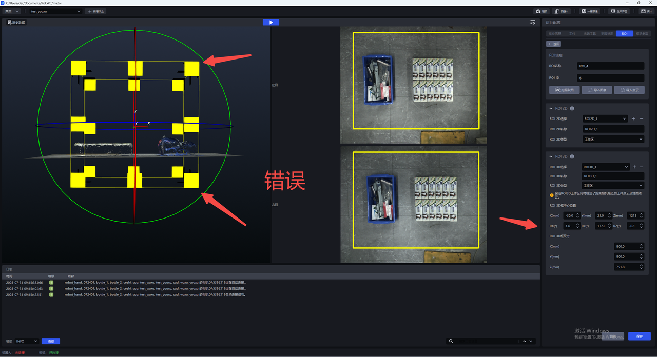
Note:
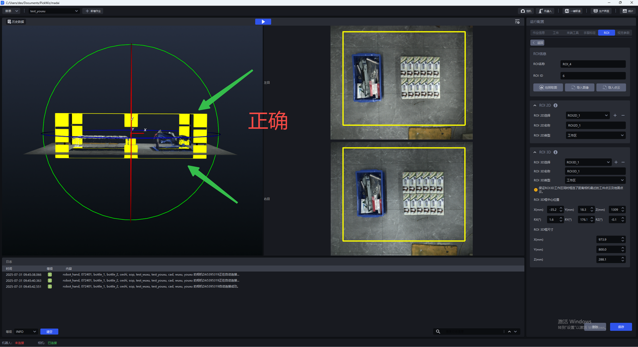
When adjusting ROI 3D, ensure that the Z-direction height of the ROI 3D workspace just includes the Point Cloud of the workpiece closest to the camera and the ground Point Cloud (as shown below).
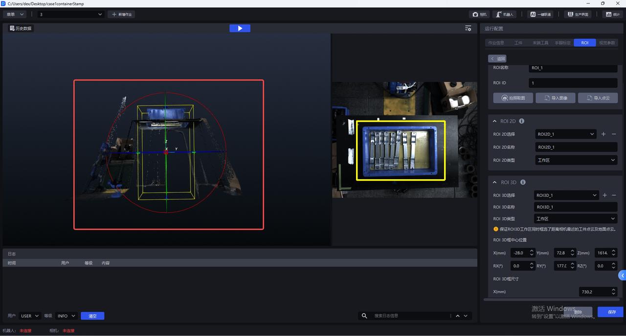
The bottom edge of the ROI 3D box should fit the ground as closely as possible, and the top surface should not be too high
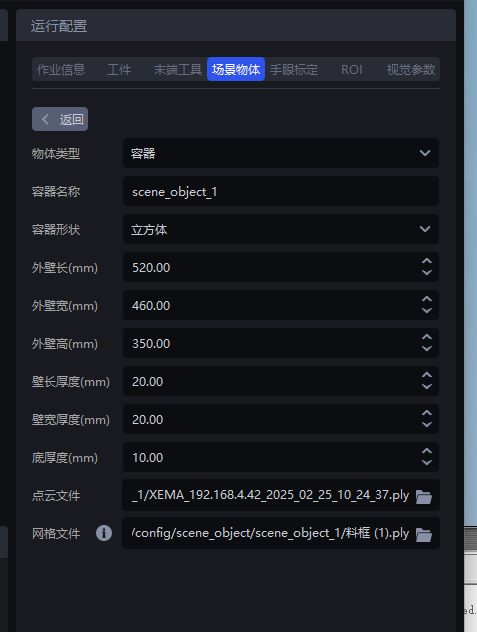
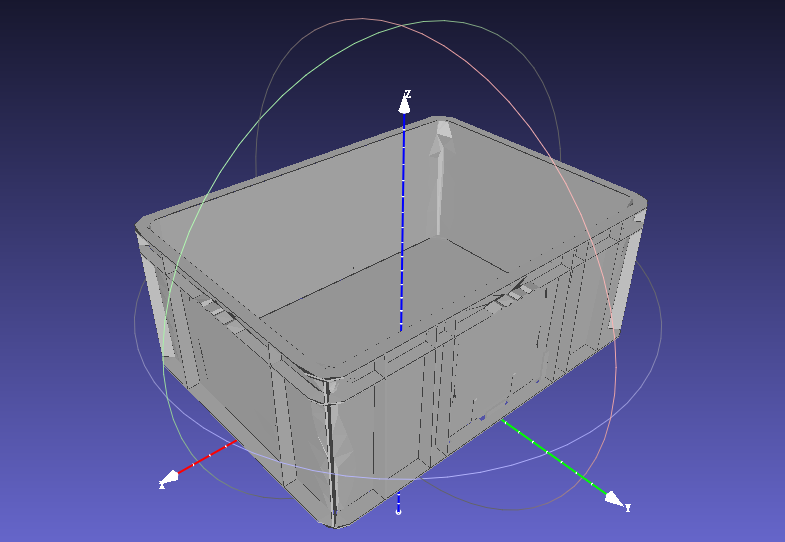
5. Configure Scene Objects
In general unordered scenes, for scenarios with a bin that use the collision detection option, Scene Objects should be configured by uploading the mesh file of the bin. The Scene Object dimensions must be consistent with the actual bin dimensions.
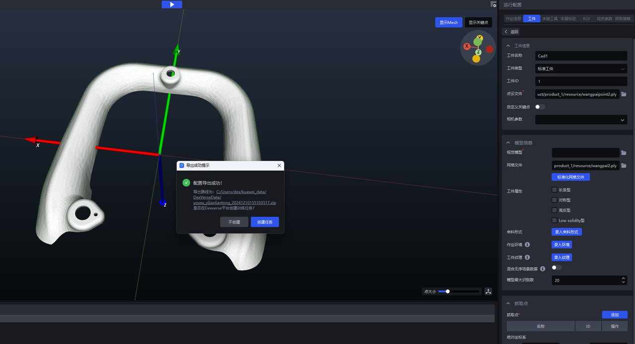
6. Create a Training Task
After configuring the camera, workpiece, and ROI, click One-Click Connection to trigger imaging model training.
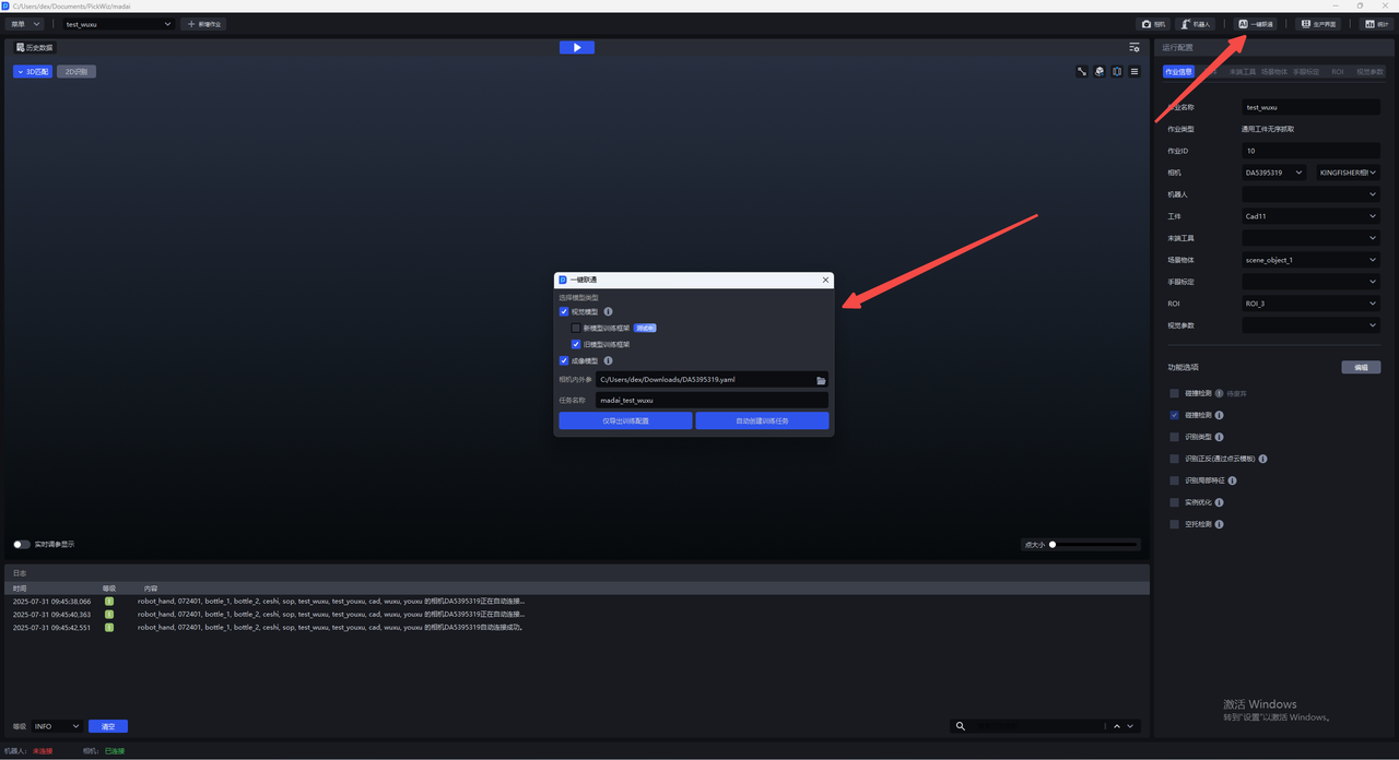
If you need to manually edit the input data, select Export Training Configuration Only; if no editing is required, select Automatically Create Training Task.
6.1 Only Export the Training Configuration
Suitable for users who need to edit the data manually. Later, you will need to manually create a training task on the dexverse platform yourself.
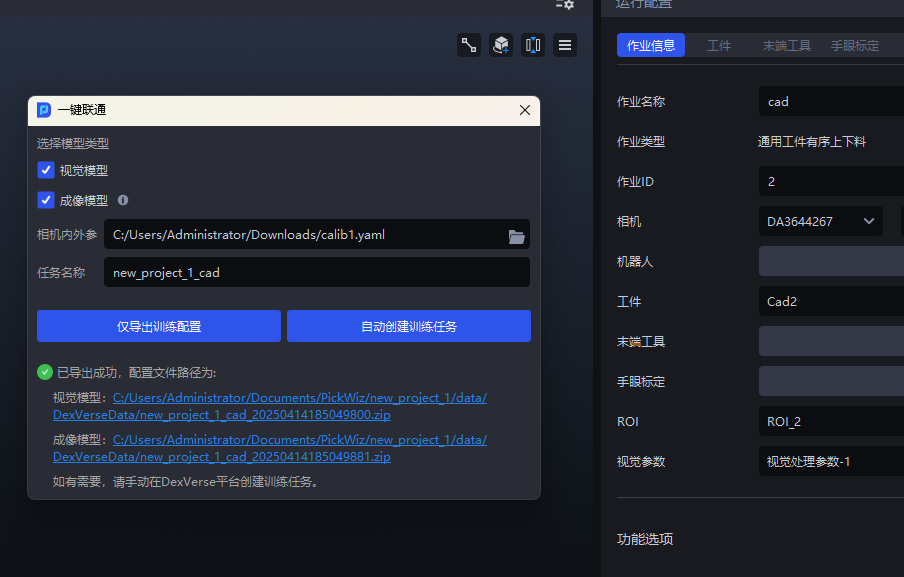
(1)On the main interface, click One-Click Connection. The One-Click Connection popup appears. Select Imaging Model, and confirm that the KINGFISHER camera is connected or that the corresponding camera model has been selected.
(2)Click Export Training Configuration Only . The software will read the intrinsic and extrinsic parameter files from the existing camera and export them to the relevant training configuration path. You can click the link at the bottom of the popup to view the contents of the data archive or modify the configuration.
(3)Manually upload the data to the Dexverse platform to create a training task. For specific steps, see DexVerse Operation Manual.
6.2 Automatically Create a Training Task
Suitable for most scenarios. After configuring workpieces/ROI and other settings in PickWiz, a training task can be created automatically on the dexverse platform.
(1)On the main interface, click One-Click Connection. The One-Click Connection popup appears. Select Imaging Model, confirm that the KINGFISHER camera is connected or that the corresponding camera model has been selected, and then give the task a name so it is easy to search for in DexVerse.
(2)Select Imaging Model , then click Automatically Create Training Task .
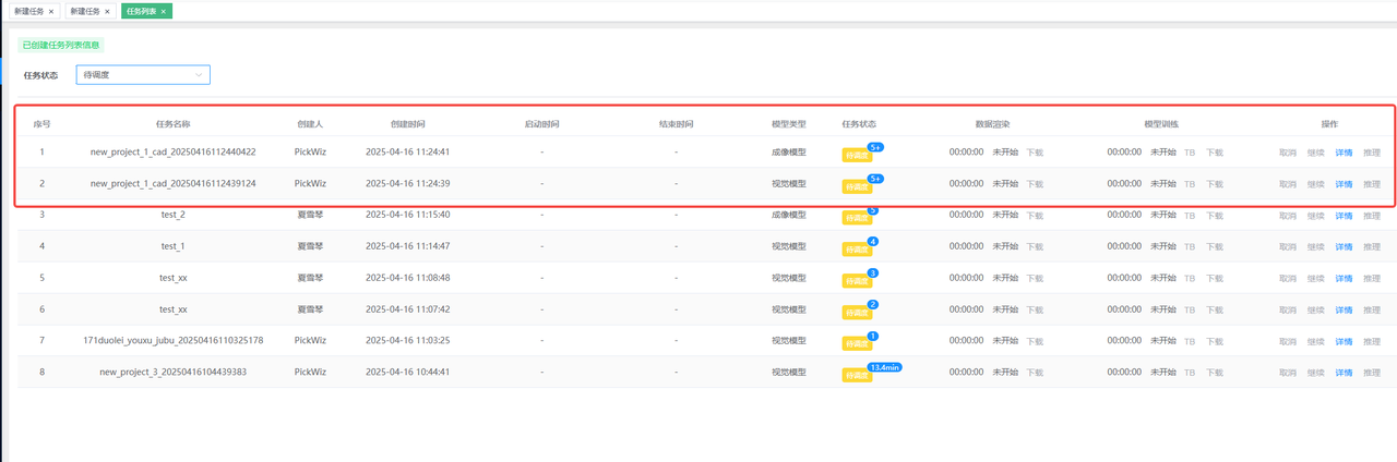
(3)Go to the Dexverse platform to view the automatically created training task. For specific steps, see DexVerse Operation Manual.
7. Train the Vision Model and Imaging Model at the Same Time
In the One-Click Connection popup of PickWiz, select both Vision Model and Imaging Model , then click Export Training Configuration Only / Automatically Create Training Task .