Collision Detection Guide
The Collision Detection function is used to detect collisions between the Tool and the bin, filter out Picking Poses that may collide, and this article mainly introduces how to configure Scene Objects and adjust related visual parameters after enabling Collision Detection.
1. Operation Guide
1.1 Bin Detection
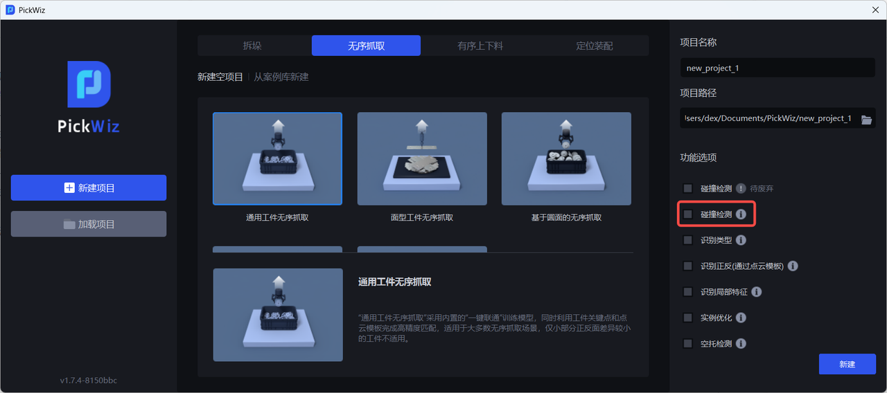
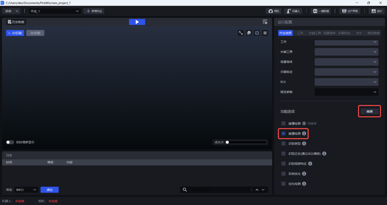
When there is a bin in the actual scene, enable the Collision Detection function when creating a new project; if it was not enabled when creating the new project, go to the task Information page, click Edit in the lower right corner, then enable Collision Detection and save
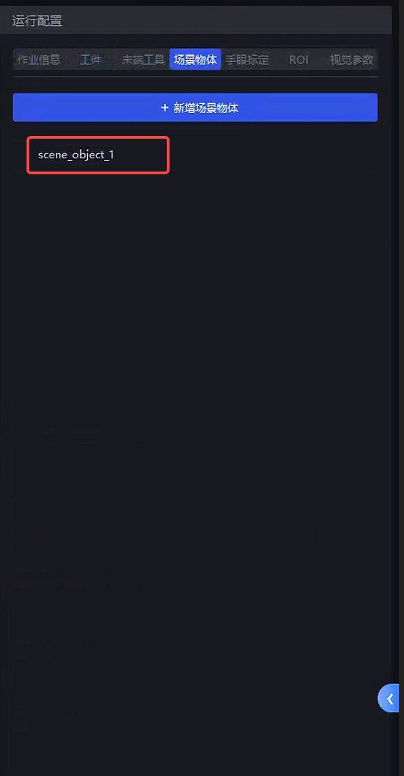
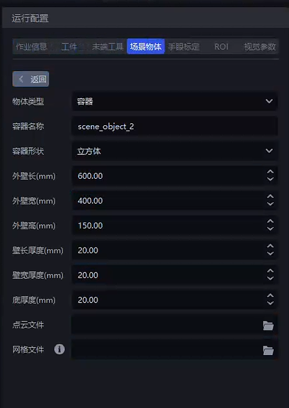
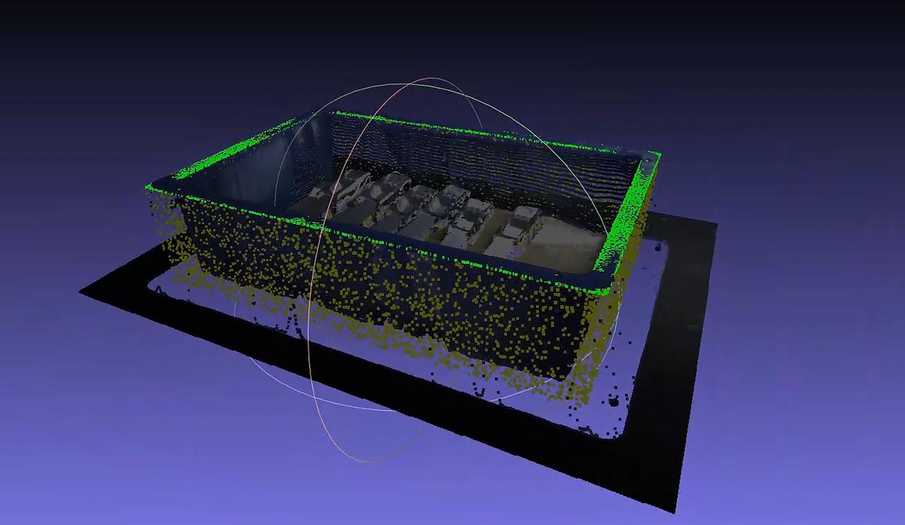
After enabling Collision Detection, Scene Object is added to the runtime configuration bar. On the Scene Object page, enter the outer wall length, width, height, and thickness of the bin
Adjust the bin detection-related parameters in Visual Parameters - 3D Calculation - Collision Detection. For details, refer to 2.1 Bin Detection.
1.2 Collision Detection Between the Tool and the Bin
In 3D Calculation - Collision Detection, you can adjust related parameters. For details, refer to 2.2 Collision Detection Between the Tool and the Bin.
2. Tuning Guide
2.1 Bin Detection
Bin extraction process:
| Function | Parameter | Description | Default Value | Value Range | Tuning Suggestion |
|---|---|---|---|---|---|
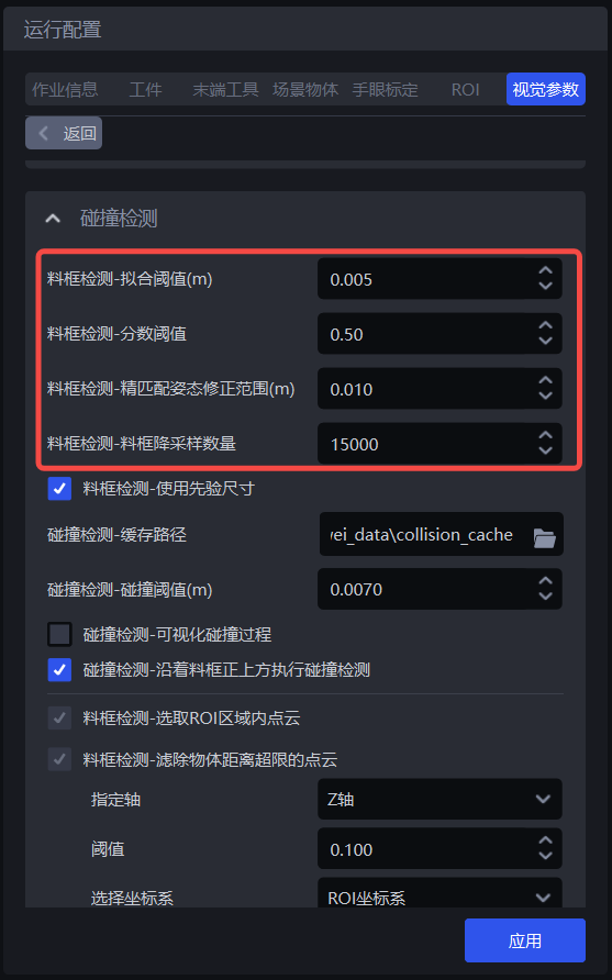
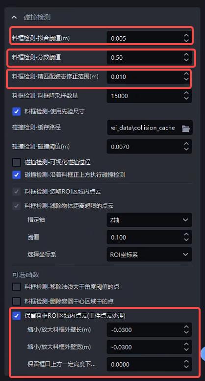
| Bin Detection - Fitting Threshold (m) | Fitting threshold. Based on the bin size, determine whether the calculated bin size is within the fitting threshold | 0.005 | [0.001, 0.05] | Between 0.003 and 0.01 | |
| Bin Detection - Score Threshold | Minimum required score threshold for bin detection. If the score is higher than the threshold, bin detection is considered successful; otherwise, it fails | 0.5 | [0.1, 1.0] | 0.5 is recommended | |
| Bin Detection - Fine Matching Pose Correction Range (m) | During bin fine matching, this is the threshold for the Point Cloud search radius and also the distance threshold for determining correct point pairs. The larger the value, the larger the search radius and the looser the condition for determining correct point pairs. The default is 0.01, and generally no change is required. | 0.01 | [0.001, 0.1] | Generally no adjustment is needed | |
| Bin Detection - Bin Downsampling Count | The downsampled point count of the bin, used for bin fine matching. The larger the point count, the faster the speed and the lower the accuracy. | 15000 | [5000, 30000] | Select according to accuracy requirements. The higher the accuracy requirement, the larger the point count | |
| Bin Detection - Use Prior Dimensions | Whether to calculate the bin according to prior dimensions. If yes, the bin must satisfy the prior dimensions and the fitting threshold; otherwise, the largest rectangle will be found as the bin | Checked | / | Generally no adjustment is needed | |
| Bin Detection - Select Point Cloud Inside ROI | Select the Point Cloud inside the ROI 3D region from the actual Point Cloud | Checked | / | Generally no adjustment is needed | |
| Bin Detection - Remove Point Cloud Beyond Object Distance Limit - Threshold | Specified Axis | Along the specified axis direction, use 95% of the bin Point Cloud height (the bin Point Cloud is from 100% to 0% top to bottom) as the reference, and remove the Point Cloud that exceeds the threshold from top to bottom along the specified axis direction | Z Axis | X/Y/Z Axis | Generally no adjustment is needed |
| Threshold | Remove the Point Cloud that exceeds the threshold from top to bottom along the specified axis direction | 0.1 | [0.001, 1.0] | Between 0.005 and 0.2 is recommended | |
| Select Coordinate System | The coordinate system of the specified axis | ROI Coordinate System | Camera Coordinate System ROI Coordinate System Object's Own Coordinate System | Generally no adjustment is needed | |
| Bin Detection - Remove Point Clouds with Normals Greater than the Angle Threshold | Angle Threshold | If the angle between the Point Cloud normal direction and the reference axis exceeds the angle threshold, the point will be removed | 15 | [0, 360] | If the target plane is a flat surface, the angle threshold is generally 5°~15°; if the target plane is a curved surface, the angle threshold is generally 15°~30° |
| Standard Normal Axis | Reference axis (default is the Z axis, that is, the vertical direction), a certain axis of the camera coordinate system. | Z Axis | X/Y/Z Axis | Generally no adjustment is needed | |
| Use ROI Coordinate System | If checked, use the ROI Coordinate System; if unchecked, use the camera coordinate system | Unchecked | / | If the bin is tilted, check Use ROI Coordinate System | |
| Bin Detection - Delete Points in the Container Center Area | Removal Ratio | The ratio of the center area to the container area. Remove the Point Cloud in the center area and keep the Point Cloud in the edge area | 25 | [0, 100] | Adjust according to the object area in the center area of the bin |
| Whether the X Axis Is the Long Edge | If checked, calculate the center area based on the length in the X-axis direction; if unchecked, compare the lengths in the X-axis and Y-axis directions and calculate the center area based on the longer edge of the two | Checked | / | If the length in the X-axis direction is the long edge, check it; otherwise, do not check it | |
| Keep Point Cloud Inside the Bin ROI Region (Workpiece Point Cloud Processing) Currently, after keeping the Point Cloud inside the bin ROI region, the data can only be accessed through historical data. Front-end display will be added in subsequent versions | Shrink/Expand Bin Outer Wall Length (m) | When there is an error in the bin dimensions and a certain amount of bin wall Point Cloud is kept, this parameter needs to be reduced; or when a certain amount of workpiece Point Cloud is filtered out, this parameter needs to be increased. A negative number means shrinking, and a positive number means expanding. | 0.0 | [-1.0, 1.0] | Generally no adjustment is needed |
| Shrink/Expand Bin Outer Wall Width (m) | When there is an error in the bin dimensions and a certain amount of bin wall Point Cloud is kept, this parameter needs to be reduced; or when a certain amount of workpiece Point Cloud is filtered out, this parameter needs to be increased. A negative number means shrinking, and a positive number means expanding. | 0.0 | [-1.0, 1.0] | Generally no adjustment is needed | |
| Keep Point Cloud Within a Certain Height Above the Bin Opening (m) | You can set a space with a certain height above the bin opening, and the Point Cloud within this space can be retained to avoid cases where the bin overflows above the opening | 0.0 | [0.0, 1.0] | Generally no adjustment is needed | |
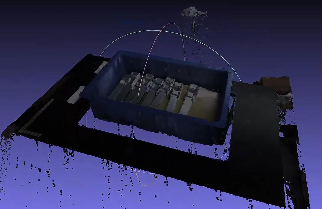
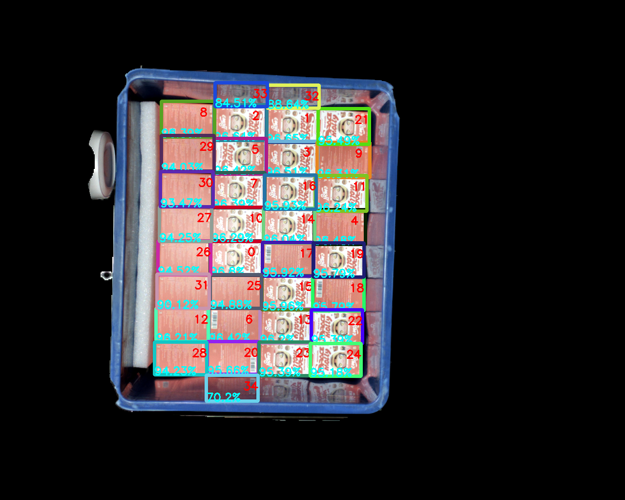
Example: Keeping the Point Cloud inside the bin ROI region (workpiece Point Cloud processing) is used to remove some reflective instances.
Abnormal Situation Description:
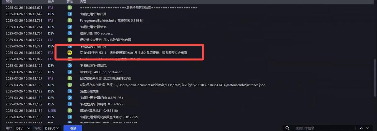
No bin detected
If no bin is detected, first check whether the entered bin dimensions are correct, then adjust Bin Detection - Fitting Threshold (m)
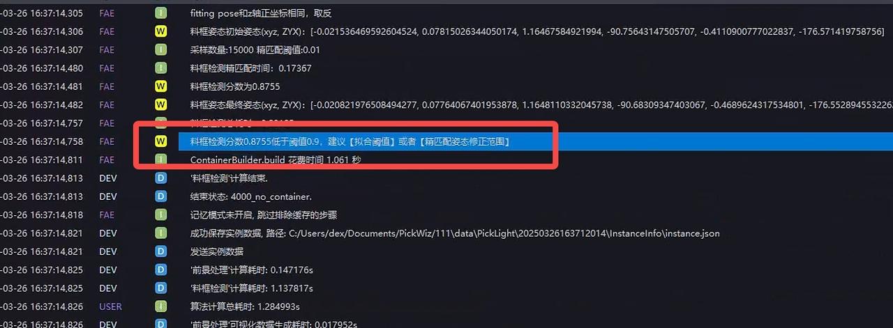
- Bin detection score is too low
The bin can be recognized correctly, but the score is too low. You can relax Bin Detection - Fine Matching Pose Correction Range (m)
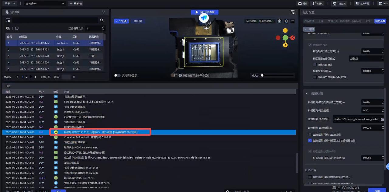
- Bin score is below the threshold
If the bin score is too low and the recognition is actually correct, modify Bin Detection - Score Threshold; otherwise, modify Bin Detection - Fine Matching Pose Correction Range (m)
2.2 Collision Detection Between the Tool and the Bin

| Parameter | Description | Default Value | Value Range | Tuning Suggestion |
|---|---|---|---|---|
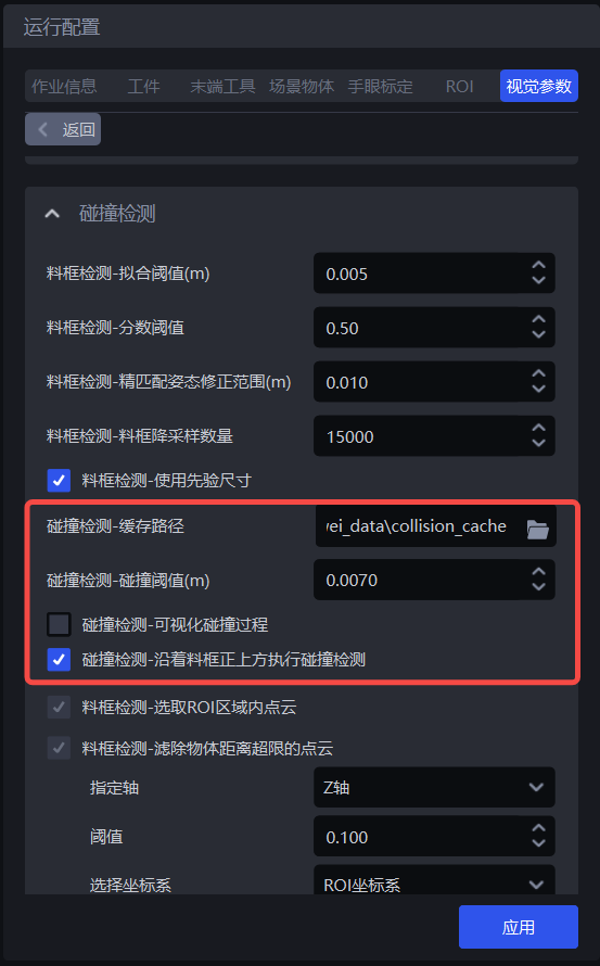
| Collision Detection - Cache Path | Save path for Collision Detection visualization results | / | / | |
| Collision Detection - Collision Threshold (m) | Collision distance threshold. If the distance between the scene and the gripper surface is less than this threshold, a collision is considered to have occurred | 0.007 | 0.001 - 1.0 | |
| Collision Detection - Visualize Collision Process | Visualize the process data of Collision Detection | Unchecked | / | |
| Collision Detection - Perform Collision Along Directly Above the Bin | Whether to perform Collision Detection along directly above the bin. If unchecked, Collision Detection is performed along the negative Z-axis direction of the Pick Point, that is, the gripper may move obliquely upward with an angle; | Checked | / |