Common Recognition and Picking Issues
1. Recognition Failure
1.1. Automatic Enhancement Color Jitter
Affected Versions: 1.4.2+
Issue: During 2D recognition, image automatic enhancement is enabled, and the output inference image shows color jitter.
Possible Cause: When the color mode used by automatic enhancement is grayscale, large changes in the workpiece material color or environment may cause color jitter.
Solution: Change the color mode of the automatic enhancement function to Lab or rgb.
1.2. Automatic Clearing of Pick Points During Runtime in a 2D Recognition Picking Solution
Affected Versions:
Issue: Pick Points are cleared automatically during runtime.
Possible Cause: This usually occurs when 2D recognition uses the image acquisition function and the task type is Positioning and Assembly (currently unsupported).
Solution: Contact the FAE for assistance.
1.3. After Importing json in Historical Data, roi Reverts to the Default Empty Value
Affected Versions:
Issue: After importing json in historical data (batch run), roi reverts to the default empty value.
Possible Cause:
Solution: This issue is resolved after upgrading to version 1.4.5.
1.4. Quadrilateral Model Defects
Affected Versions:
Issue: When quadrilateral workpieces use the general model, instance segmentation may detect some internal planes of the workpiece in certain scenarios.
Possible Cause:
Solution: 1. Adjust the pitch angle to below 45°; 2. Increase the distance between the Camera and the workpiece; 3. Due to scene limitations of the quadrilateral model, the issue may not be solvable.
1.5. Discontinuous Edges in Recognition Results
Affected Versions: 1.4.2+
Issue: In recognition results, the edges are discontinuous, and the extracted Mask edges appear jagged.
Possible Cause: Edge enhancement is set too high.
Solution: 1. Reduce the edge enhancement parameter; 2. Replace the industrial PC with one of a higher configuration.
1.6. Stereo Camera Capture Results Drift
Affected Versions: 1.4.2+
Issue: Stereo Camera capture results drift.
Possible Cause: If the stereo Camera is subject to vibration or large temperature changes, the internal Camera parameters may become abnormal.
Solution: Recalibrate the stereo Camera.
1.7. Low Detection Score for the General Model of Surface-Type Workpieces
Affected Versions: 1.4.2+
Issue: The general model for surface-type workpieces produces low detection scores.
Possible Cause:
The workpiece itself does not have much color texture, and the appearance differences are small.
The workpieces are heavily occluded after stacking.
Large changes in the environment or lighting.
The workpiece is not at the center of the image.
Solution:
If the workpiece has CAD or mesh data, you can use One-click Connection to train a Vision Model.
You can use the Instance Optimization feature to improve the recognition score.
1.8. Sack Detection Defects
Affected Versions: 1.4.2+
Issue: In sack detection results, the sacks may be connected together and cannot be separated into individual instances.
Possible Cause: Too many sacks are stacked and squeezed against each other.
Solution: Contact the FAE for assistance.
1.9. Carton Detection Defects
Affected Versions: 1.4.2+
Issue: In single-carton depalletizing, a single face of a carton may be detected, or multiple cartons may be detected as connected together.
Possible Cause:
The Camera pitch angle is greater than 30°.
Cartons are heavily squeezed during stacking.
The height difference between cartons is large.
Solution:
Adjust the Camera pitch angle to below 30°.
Minimize squeezing during stacking.
Ensure that carton heights are consistent.
1.10. Cylinder Workpiece Detection Defects
Affected Versions: 1.4.2+
Issue: Cylinder workpieces may be detected as connected together.
Possible Cause: Cylinder workpieces are stuck together, or the Camera angle is inappropriate.
Solution:
Adjust the Camera pitch angle to around 10°.
Minimize sticking between workpieces.
2. 3D Registration Failure
2.1. Multiple Instances Appear After Point Cloud Segmentation in a Positioning and Assembly Scene
Affected Versions: 1.4.2+
Issue: For surface-type workpieces in a Positioning and Assembly scene, multiple instance Point Clouds remain after segmentation, resulting in no output.

Possible Cause: The boundary between the workpiece and the background in the Scene is unclear, resulting in incorrect instance segmentation.
Solution: You can use the bin detection in Collision Detection as background segmentation for the workpiece Point Cloud.
2.2. 3D Registration Failure in a Positioning and Assembly Scene
Affected Versions: 1.4.2+
Issue: After Point Cloud segmentation, there is only one workpiece instance, but 3D Registration cannot output results.
Possible Cause:
Recalibration has not been performed for more than 4 hours.
The workpiece Point Cloud quality is too poor.
During image capture, the workpiece is outside the ROI 3D range or too close to the boundary.
Solution:
Capture another image to check the Point Cloud boundary quality.
Perform eye-hand calibration inspection again on this workpiece.
Adjust ROI 3D so that the workpiece is positioned at the center of the image.
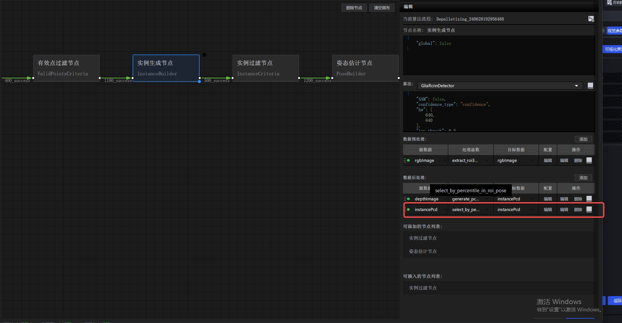
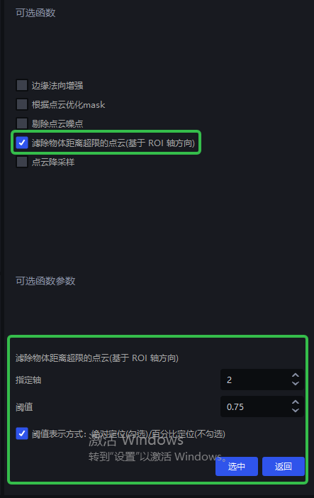
2.3. In a Positioning and Assembly Scene, the Input Point Cloud Is Not Cropped by Occlusion
Affected Versions: 1.4.2+
Issue: For surface-type workpieces in a Positioning and Assembly scene, when the template Point Cloud is used for occlusion cropping, part of the current Point Cloud is not cropped away.
Possible Cause: Noise exists in the Scene itself, causing occlusion cropping to fail.
Solution: Version 1.7.2 and above currently supports filtering Point Cloud data whose distance exceeds the limit based on a Threshold. You can use this function to remove noise.
2.4. In Mirror Mode, Beam Occlusion Causes Symmetry-Center Pose Optimization Failure
Affected Versions: 1.4.2+
Issue: Large occlusions on both sides of the object surface cause pose optimization to fail.
Solution:
Adjust the workpiece position so that the occlusion on the workpiece surface is as even as possible.
2.5. Pick Point Offset
Affected Versions: 1.4.2+
Issue: The Pick Point position is offset.
Possible Cause:
The workpiece was not fully captured, and the edges were cut off.
The Pick Point is located inside an occluded area of the workpiece.
Camera parameters changed, or thermal drift is large.
Solution:
Capture another image to check whether the workpiece is at the center of the image.
Change the Pick Point location to avoid occluded areas.
Recalibrate or perform real-time correction for visual thermal drift.
2.6. Concave Workpieces Generate Pick Points with Incorrect Orientation
Affected Versions: 1.4.2+
Issue: Concave workpieces may sometimes generate Pick Points facing the opposite direction.
Possible Cause: Noise or missing data exists in the Scene Point Cloud, causing errors in normal direction judgment.
Solution:
Enable outlier removal.
Adjust the Camera angle to avoid excessive data loss in deep-hole areas.
3. Rigid Transformation Failure
3.1. Stable Output Cannot Be Achieved When Either the Front or Back Side of a Workpiece May Face Up
Affected Versions: 1.4.2+
Issue: Either the front or back side of the workpiece may face up, but only one template is configured.
Possible Cause: The template orientation does not match the actual incoming material orientation.
Solution:
Use the Recognize Front and Back (via Point Cloud Template) feature.
Create separate template Point Clouds for the front and back sides.
3.2. Workpiece Pose Jitter
Affected Versions: 1.4.2+
Issue: During repeated runs, the output pose of the same workpiece fluctuates significantly.
Possible Cause:
Point Cloud boundary quality is unstable.
The Pick Point is not located on a stable structural feature.
There is substantial noise in the Scene Point Cloud.
Solution:
Optimize camera imaging quality adjustment.
Move the Pick Point to a structurally stable and unobstructed location.
Add filtering functions in Point Cloud preprocessing.