Slip Sheet Detection Guide
The Slip Sheet Detection function is enabled in scenarios where the slip sheet needs to be picked. After it is enabled, the slip sheet can be picked after normal workpiece picking is completed. This article mainly introduces how to adjust related visual parameters after enabling Slip Sheet Detection.
1. Operation Guide
The Slip Sheet Detection function is applicable to depalletizing scenarios
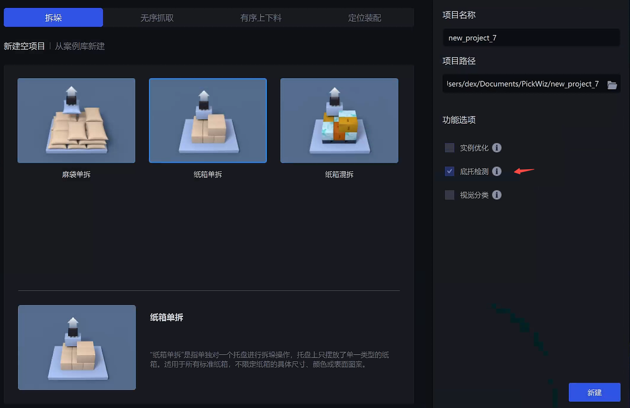
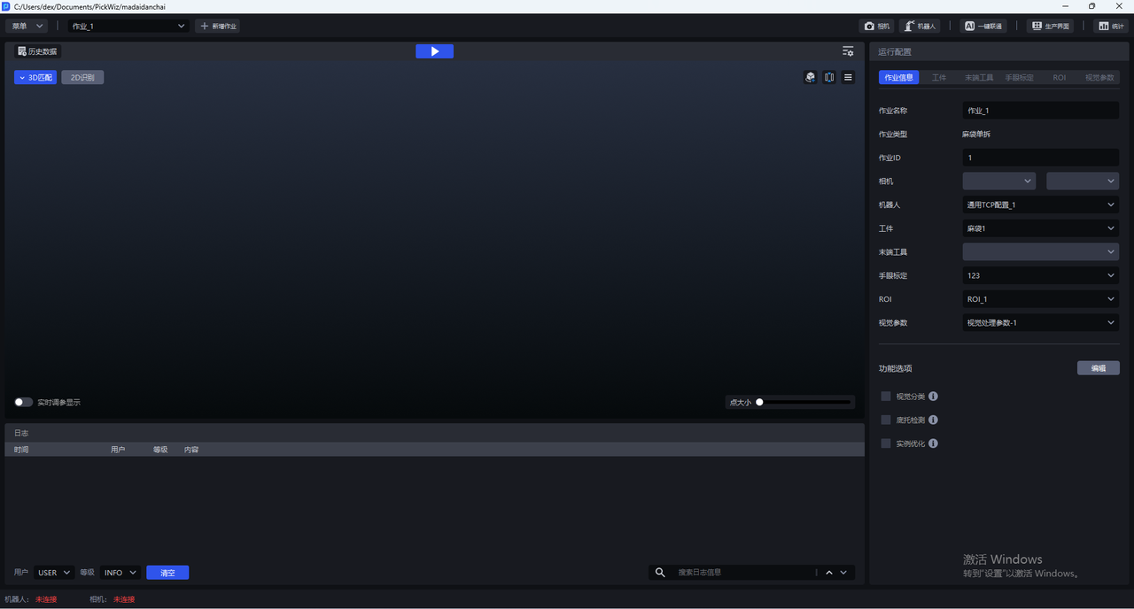
- When there is a slip sheet in the actual scene, enable the Slip Sheet Detection function when creating a new project; if it was not enabled when creating the new project, go to the task Information page, click Edit in the lower right corner, and then enable Slip Sheet Detection
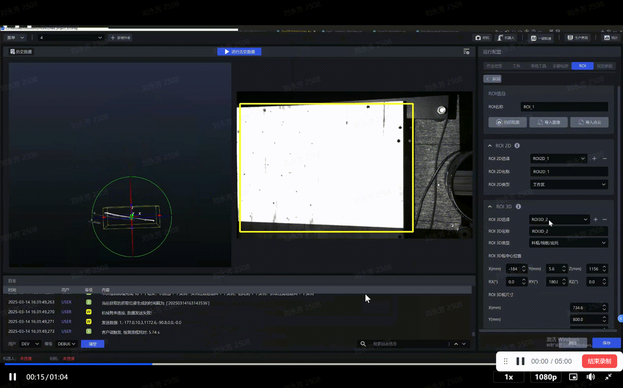
- Create an ROI on the ROI page, adjust the ROI 3D box to fully cover the Target Object, then create an ROI3D_2 and select ROI 3D Type as Bin/Pallet/Slip Sheet
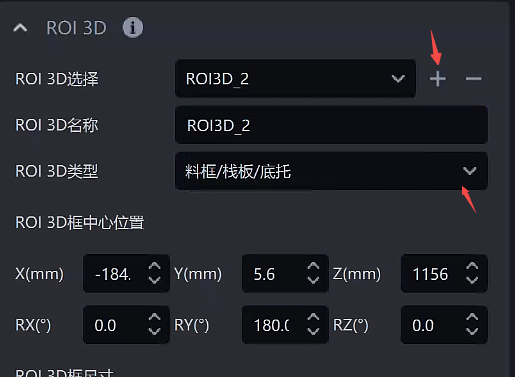
Adjust the size of ROI3D_2 so that it only includes the slip sheet area
2. Tuning Guide
After selecting each configuration item in task Information, adjust parameters in Visual Parameters - 3D Calculation - Slip Sheet Detection
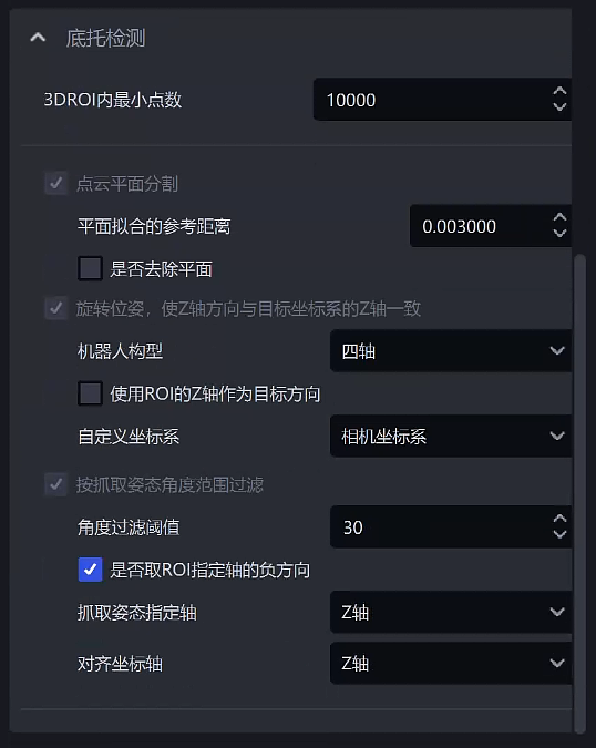
| Parameter | Description | Default Value | Value Range | Tuning Suggestion | |
|---|---|---|---|---|---|
| Minimum Point Count in 3DROI | If the number of Point Cloud points extracted within the ROI 3D workspace is less than this value, it indicates that the workpieces have already been completely picked, and the process automatically enters the Slip Sheet Detection part | 10000 | 0-100000 | The value should be smaller than the Point Cloud count of a single workpiece | |
| Point Cloud Plane Segmentation | Reference Distance for Plane Fitting | Points whose distance to the plane is lower than the reference distance are considered points on the plane and will be retained; otherwise, they are considered points outside the plane and will be filtered out. The larger the value, the thicker the retained plane. | 0.003 | 1e-6 ~ 10 | Decrease this value when high Point Cloud accuracy is required, and increase it when Point Cloud accuracy requirements are lower |
| Remove Plane | If checked, remove the fitted plane; if unchecked, keep the fitted plane | Unchecked | / | Usually no adjustment is needed | |
| Rotate the pose so that the Z-axis direction matches the Z-axis of the target coordinate system | Robot Configuration | Set according to the number of robot arm axes of the on-site robot. If a six-axis robot is used as a four-axis robot, it should be set as four-axis | Four-axis | Four/Six-axis | Select according to on-site requirements |
| Use the ROI Z-axis as the target direction | Only takes effect when Robot Configuration is set to four-axis. If checked, the Z-axis direction of the Picking Pose is consistent with the Z-axis direction of the ROI coordinate system; if unchecked, the Z-axis direction of the Picking Pose is consistent with the Z-axis direction of the camera coordinate system | Unchecked | / | Usually no adjustment is needed | |
| Custom Coordinate System | The coordinate system of the Picking Pose | Camera Coordinate System | Default Coordinate System; Camera Coordinate System; ROI Coordinate System; Robotic Arm Coordinate System | Usually no adjustment is needed | |
| Filter by Picking Pose Angle Range | Angle Filter Threshold | Calculate the maximum angle between the specified axis of the Picking Pose and the specified axis of the ROI coordinate system. Pick Points whose angle is greater than the angle filter threshold will be filtered out | 30 | -360~360 | Generally keep it unchanged. If the incoming material is greatly tilted and still needs to be picked, it is recommended to increase the threshold |
| Whether to Use the Negative Direction of the Specified ROI Axis | If checked, use the negative direction of the specified axis of the ROI coordinate system for angle calculation; if unchecked, use the positive direction of the specified ROI axis for angle calculation | Checked | / | Usually no adjustment is needed | |
| Specified Axis of the Picking Pose | Specify an axis of the Picking Pose to calculate the angle | Z Axis | X/Y/Z Axis | Usually no adjustment is needed | |
| Alignment Axis | Specify an axis of the ROI coordinate system to calculate the angle | Z Axis | X/Y/Z Axis | Usually no adjustment is needed | |