KINGFISHER Series Camera User Manual
1. Product Introduction
The KINGFISHER intelligent 3D Camera is based on binocular stereo imaging technology. By simulating human binocular vision, it uses two cameras to capture images from different angles and, through intelligent algorithms trained with Sim2Real, accurately reconstructs a Scene's 3D Point Cloud from two image sets captured at different angles in as little as 0.5s under various ambient lighting conditions. It addresses the shortcomings of traditional 3D Cameras, such as sensitivity to ambient light, slow imaging speed, short service life, and high cost, effectively improving the stability of the vision system and bringing innovative breakthroughs to the field of 3D imaging.
2. Safety Precautions
Please read the safety precautions carefully and operate strictly in accordance with the following specifications. Otherwise, the Camera may be seriously damaged. Dexforce is not responsible for any resulting maintenance issues.
Do not immerse in water
Do not place near fire
Do not disassemble the device
Do not connect the Power Supply without authorization
Do not extend the network cable without authorization
Do not use the Camera in humid environments, environments with condensation, or environments with high dust levels
Do not use the Camera in environments with strong magnetic fields or high-voltage discharge equipment (such as electric welders)
Avoid external impacts or drops. If this occurs, contact personnel for inspection and repair
Keep away from equipment such as laser marking machines and engraving machines that may damage the Camera. If such equipment must be used, contact company personnel for confirmation
Do not use beyond the specified range. Operating distance: XEMA-P:100-150mm;XEMA-DCW:0.3-0.5m;XEMA-SCW:0.5-1m;XEMA-LCW:1-2.5m;SPARROW:0.3-0.5m;FINCH:1.5-3.5m:For special customization, communicate requirements with the Camera team in advance
Use the Camera strictly within the allowable high- and low-temperature range specified in the product specification.
3. Specifications
| Parameter | KINGFISHER-S-601 | KINGFISHER-S-1001 | KINGFISHER-W-3003 | KINGFISHER-S-1201W | KINGFISHER-W-1201W | KINGFISHER-W-300W |
|---|---|---|---|---|---|---|
| Baseline | 60 | 150 | 400 | 150 | 400 | 400 |
| Field of View | 46°/42°(H/V) | 48°/39°(H/V) | 50°/43°(H/V) | 59°/47°(H/V) | 60°/46°(H/V) | 60°/45°(H/V) |
| Resolution | 1280*1024 | 1280*1024 | 1280*1024 | 4024*3036 | 4024*3036 | 2048*1536 |
| Recommended Working Distance(mm) | 200 - 500 | 500 - 2000 | 1500 - 3500 | 500 - 2000 | 1500 - 3500 | 1500 - 3500 |
| Field of View(mm) | Near Field of View135*157 Far Field of View433*393 | Near Field of View455*355 Far Field of View1803*1425 | Near Field of View1452*1166 Far Field of View3274*2721 | Near Field of View559*440 Far Field of View2283*1760 | Near Field of View1774*1276 Far Field of View4012*2978 | Near Field of View1605*1270 Far Field of View3873*2965 |
| Typical Capture Time(s) | 1 | 1 | 1 | 1 | 1 | 1 |
| Repeatability(mm) | 136 | 259 | 272 | 259 | 272 | 376 |
| Interface | GigE | GigE | GigE | GigE | GigE | GigE |
| Power Supply | POE | POE | POE | POE | POE | POE |
| Dimensions(mm) | 155*145*60 | 209*134*46 | 457*129*48 | 209*134*46 | 457*129*48 | 457*129*48 |
| Weight(kg) | 1.1 | 1.0 | 1.5 | 1.0 | 1.5 | 1.5 |
4. Installation and Connection
4.1 Unboxing Inspection
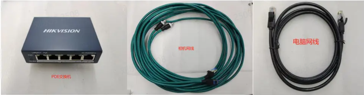
| Accessory Name | Quantity | Purpose |
|---|---|---|
| KINGFISHER Camera | 1 | Image acquisition |
| Standard Gigabit network cable | 1 | Connect the Camera and transmit data |
| Standard power cable | 1 | Connect the Camera and supply power |
| Matching Calibration Board | 1 | Parameter inspection and Extrinsic Parameter calibration |
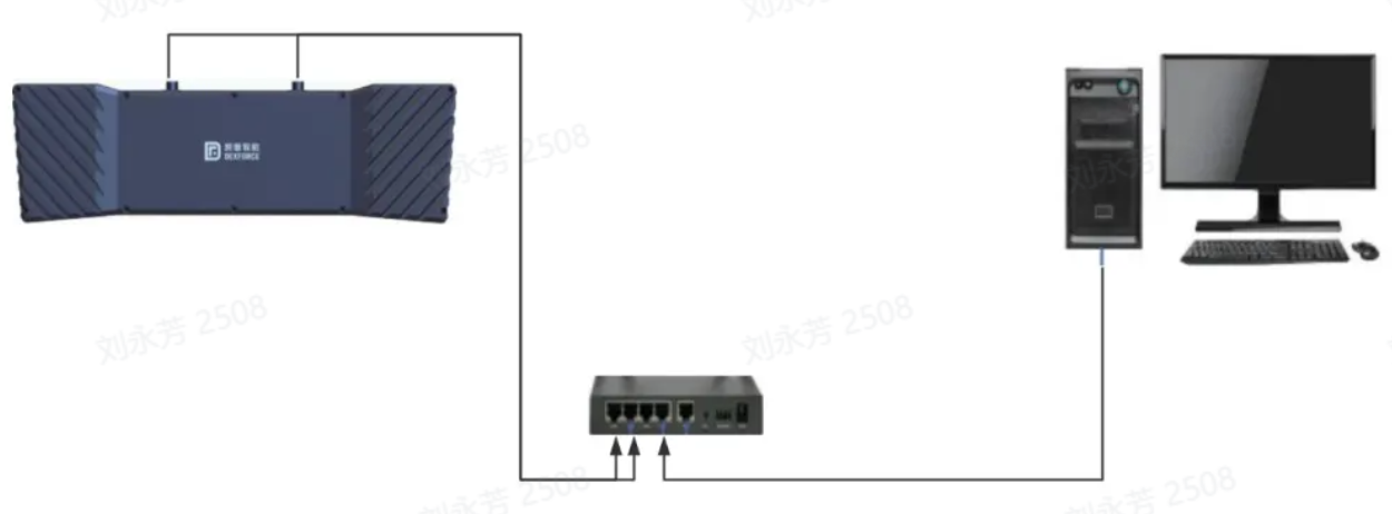
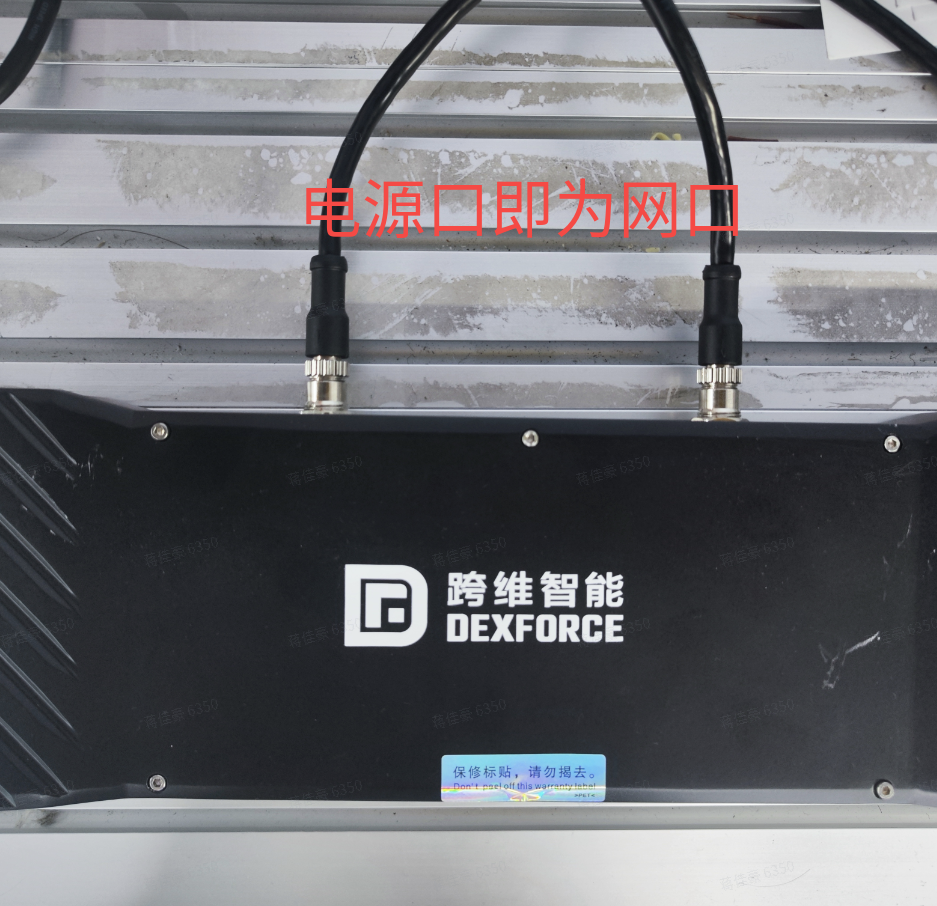
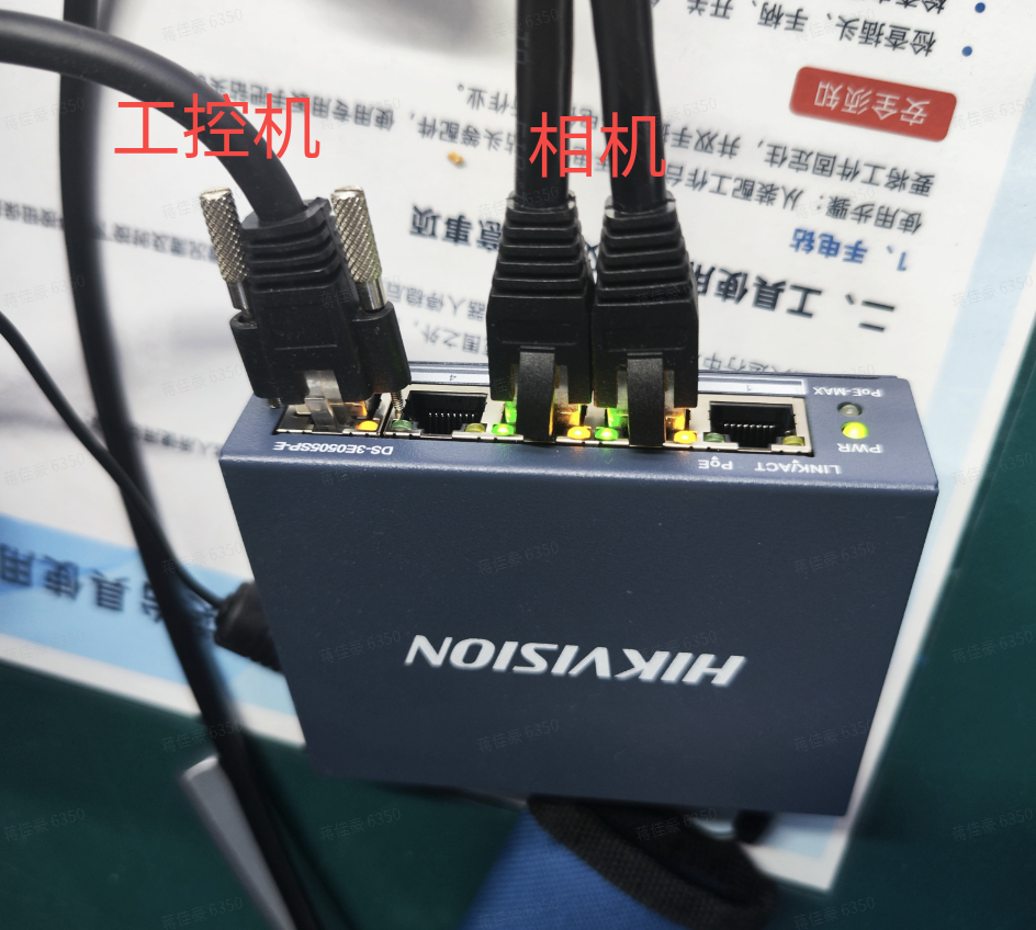
4.2 Hardware Installation
Connect the Camera to the POE switch through a network cable. The POE switch supplies power to the Camera. Then connect the computer network cable to the POE switch.
4.3 MVS Connection and Configuration
Installing MVS
MVS is Hikrobot's industrial Camera client software. It provides functions such as real-time preview of Camera images, modification of Camera device Parameters, image capture, video storage, and online device upgrades. It helps engineers and developers quickly configure and debug Cameras to ensure the accuracy and stability of image acquisition.
Dexforce currently uses MVS to configure and debug KINGFISHER Cameras. This software is already installed on the Vision system industrial PC (Industrial Personal Computer). If you need to install it yourself, use the following address to download the software: https://www.hikrobotics.com/cn/machinevision/service/download/?module=0
Configure the standard Camera connection in MVS and obtain the Intrinsic/Extrinsic Parameter calibration files
Binocular windows PickWiz deployment (application-oriented) (internal),refer to the linked document's demo video or section 3.1~3.2
Binocular Windows PickWiz deployment (application-oriented)
Purpose
This section explains how to complete basic configuration and joint-debugging preparation for machines delivered to the site.
Required process: modify the Camera IP so it can be connected -> connect the Camera in PickWiz and configure it to output a Point Cloud -> red-line image verification (Camera accuracy).
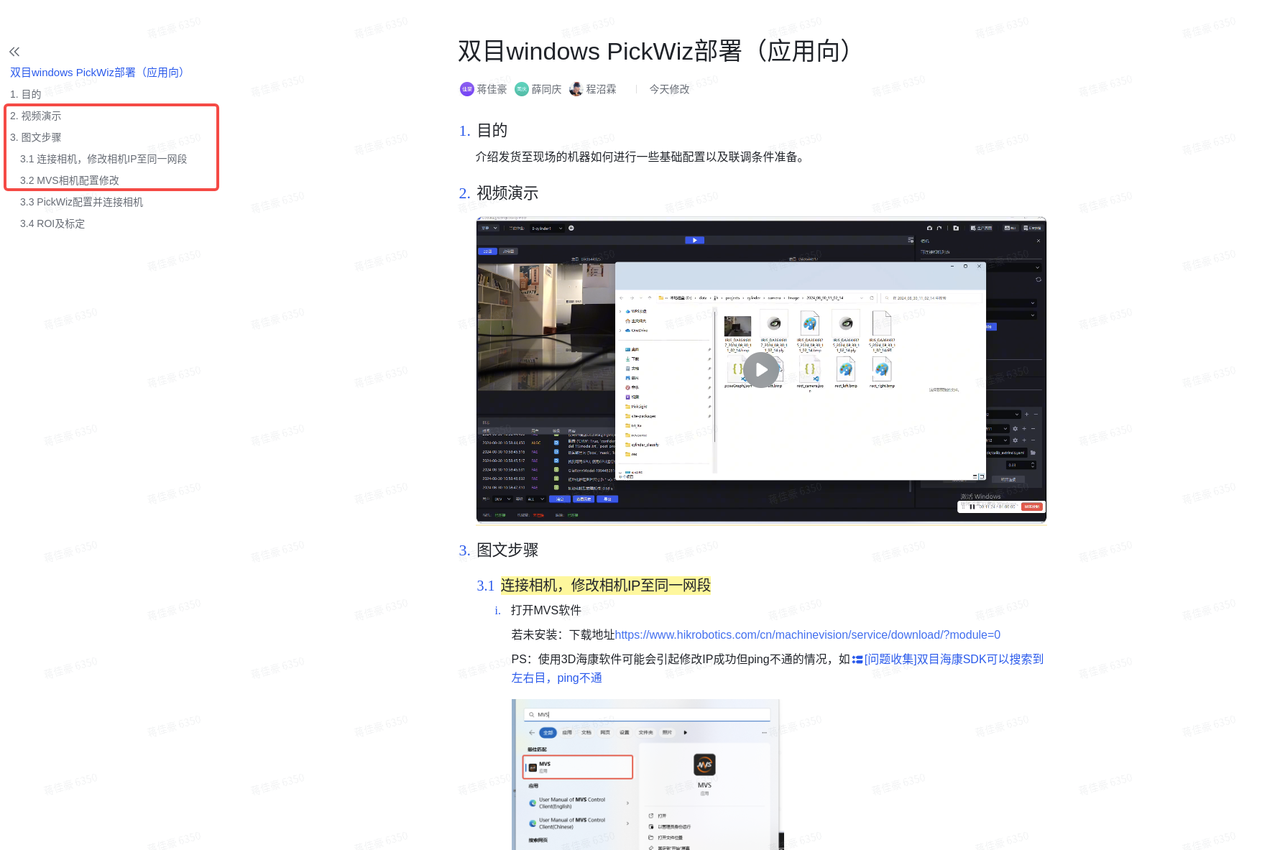
Video demonstration
Text and image steps
Connect the Camera and change the Camera IP to the same network segment
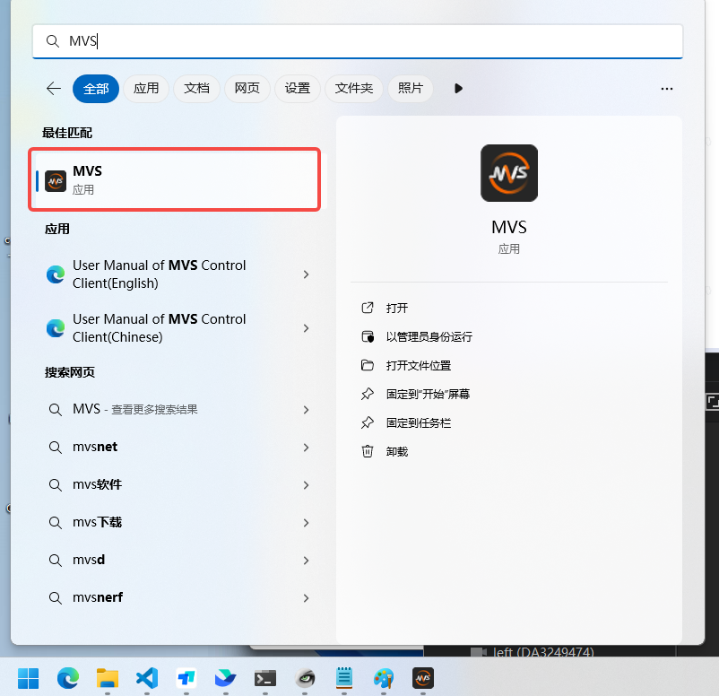
Open MVS.
If not installed: Download link
PS: When Hikrobot 3D software is used, the IP may appear to be changed successfully but still cannot be pinged, as shown below
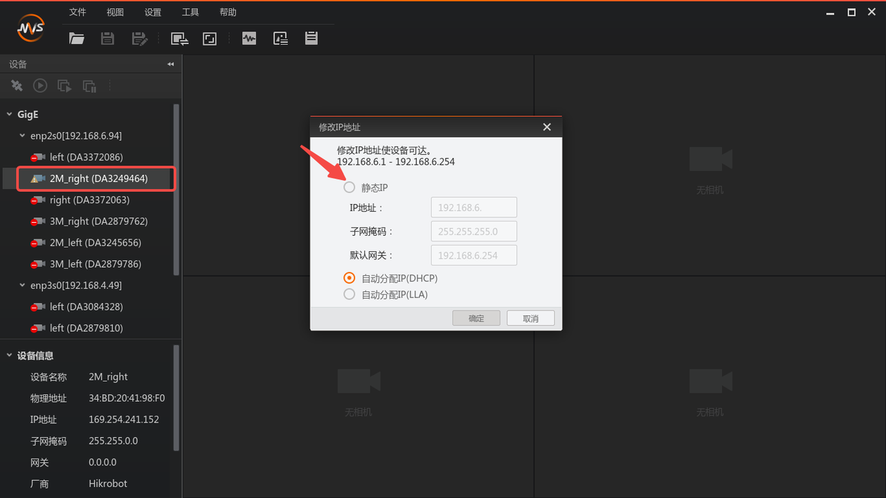
In the MVS Camera list on the left, double-click the Camera you want to connect. If it cannot be connected, modify the IP. The Camera IP must be changed to the same network segment as the industrial PC.
If the Camera is directly connected to the industrial PC, it is recommended to set the computer IP to a static IP first, and then set the Camera IP in MVS to a static IP in the same network segment.
If you want to use automatic acquisition, first change the IP to a static IP (connectable state). After the connection is established, change the IP again to "Auto Assign IP (DHCP)".
Record the Camera serial number here. For example, if the Camera name is 2M_right(DA3249464), then the serial number is DA3249464, which will be used later.
MVS Camera configuration changes
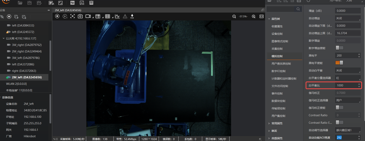
Turn off auto white balance (set the tone to 0; it is recommended that the balance ratio values of the two Cameras remain consistent)
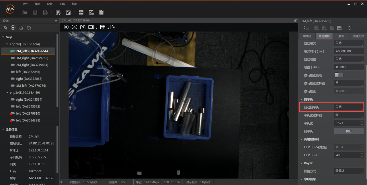
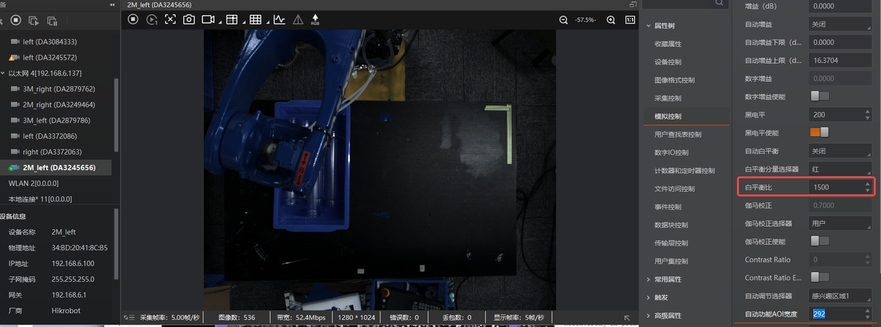
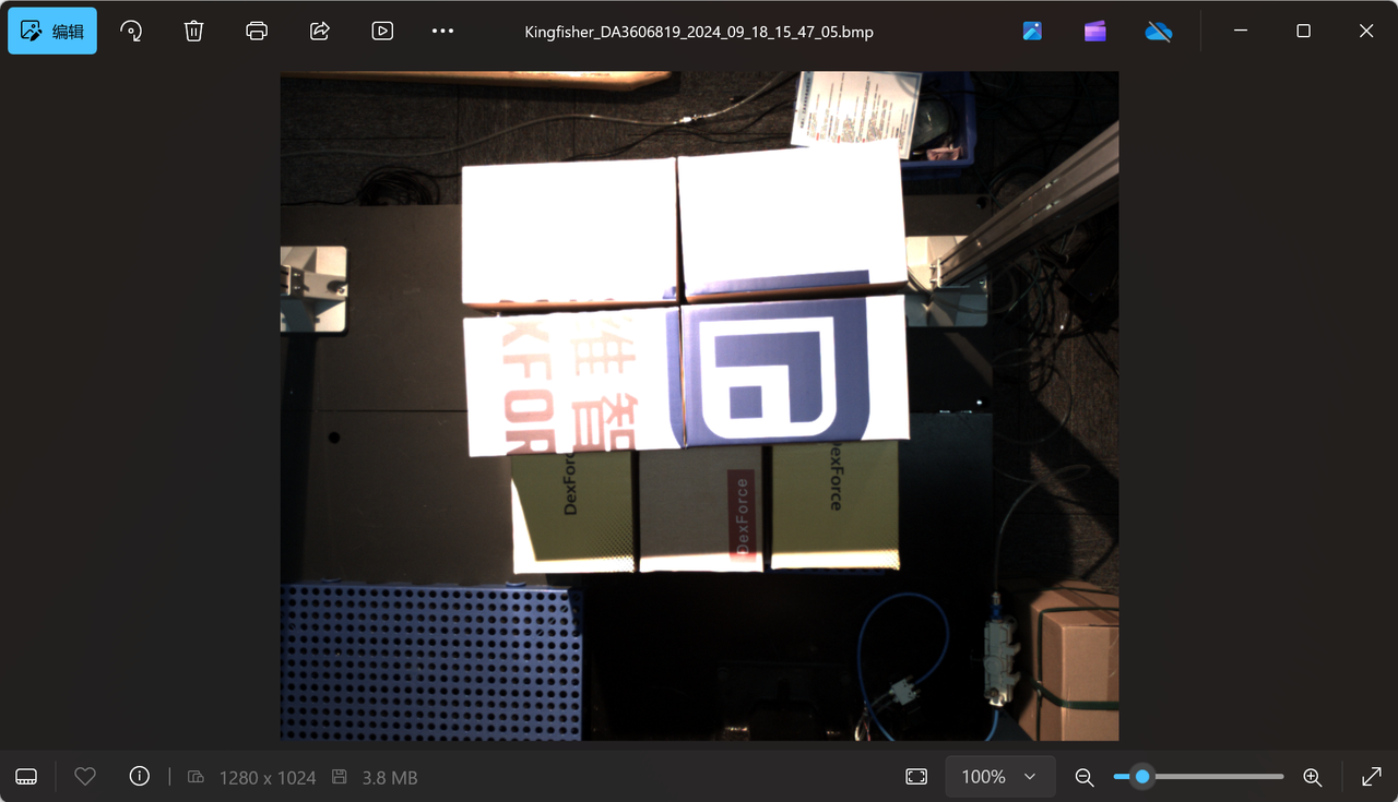
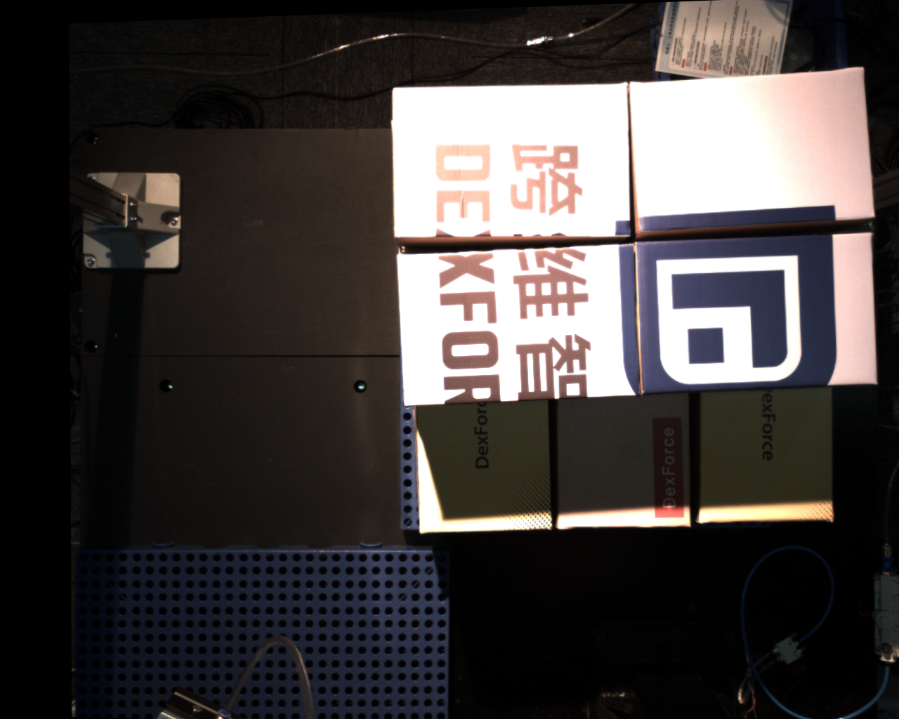
If the white balance values of the two Cameras are different, the image tones will be inconsistent, as shown in the two images below.
Recommended normal display effect:
Set the "White Balance" value to 1500. PS: High resolution tends to be cooler in tone, so 1800 can be used. In short, it should be consistent with human visual perception.
Set the "White Balance Selector" to "Red".
Auto Exposure AOI settings
Click the box indicated by the arrow, then click "Edit" and draw the AOI.
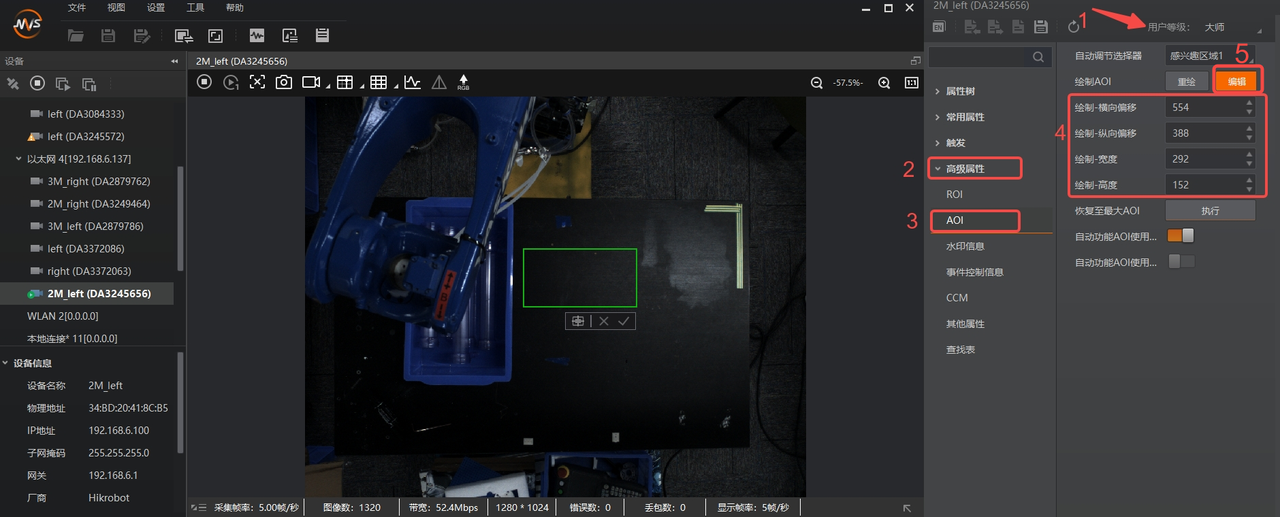
"Auto Exposure AOI" means that only the exposure condition within the AOI is considered so that the texture inside the box is clear. However, the auto exposure value is global, so the "area of concern" may be clear while the rest is overexposed.
A green box will appear.
Place the mouse at the center of the green box and drag to move the AOI area.
Place the mouse on the green box border and drag to resize the AOI area.
After drawing the AOI, record the AOI box data and enable "Auto Function AOI Intensity" as shown below.
AOI box data includes: horizontal offset, vertical offset, width, and height, which must be entered manually in the PickWiz software Camera Parameters.
In the image preview box, right-click and select "Complete" to finish the AOI configuration.
Close MVS and disconnect the Camera.
4.4 PickWiz Configuration and Camera Connection
PickWiz software configuration
Import the model
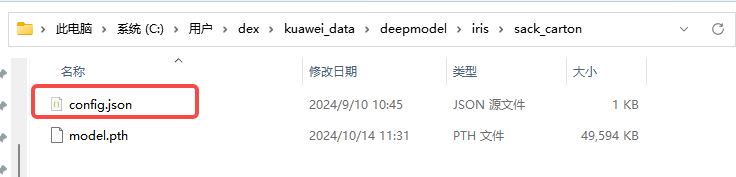
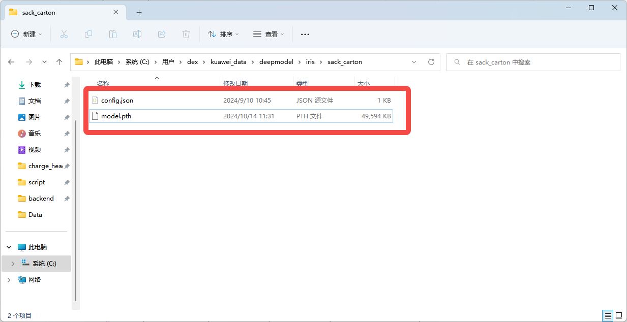
After obtaining the binocular model pth file, place the pth file in the kuaweidata/deepmodel/iris/sack\_carton/ directory and rename it to model.pth. For details on how to obtain it, see section 3.3 of Binocular windows PickWiz deployment (application-oriented)(internal)
Open the software for connection and Parameter configuration.
config.json configuration: The Path is shown below. If it does not exist, create a file with the same name. Focus on modifying the max\_disp Parameter.
{//content description "matcher_type": "pth",//model type, "pth" or "trt" "max_disp": 256,//disparity value, //disparity calculation formula: disp = fx * baseline / distance "igev_refine_iters": 32,//number of iterations "scale_x": 1.0,//scaling ratio in the x direction of the 2D image "scale_y": 1.0,//scaling ratio in the y direction of the 2D image "rectify_enlarge": false,//whether to restore the global field of view "roi_delta_x": 0//ROI2D window offset in the x direction }
The max_disp parameter needs special attention. Calculate it using the formula. If it is too large, it will introduce noise; if it is too small, disparity prediction errors will occur. max_disp means the maximum disparity. Calculate it once for the maximum working distance and once for the minimum distance, and take the larger value.
Calculation formula: disp = baseline length * camera Intrinsic Parameter fx / distance from the object
Connection
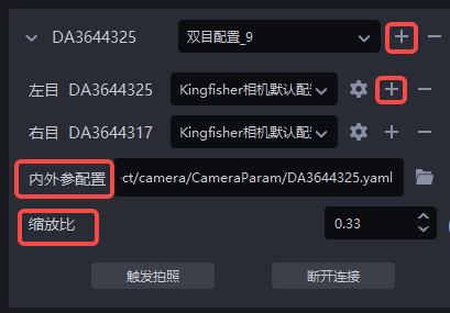
Check the binocular configuration; if it does not exist, create one with the + button.
Different Camera Parameters can be set for the left and right Cameras.
For importing Intrinsic/Extrinsic Parameter configuration, refer to section 3.3 of Binocular windows PickWiz deployment (application-oriented)
For high resolution, first set the scale ratio to 0.33(3036*4024) to prevent full-image Inference from exhausting GPU memory. No changes are needed for low resolution(1024*1280)
Parameter introduction and configuration(this section is long; reading all of it is recommended)
4.5 Download Intrinsic/Extrinsic Parameter Calibration Files
The Intrinsic/Extrinsic Parameter calibration files are the factory configuration files for Dexforce Cameras and are used to describe the relationship between the left and right Cameras.
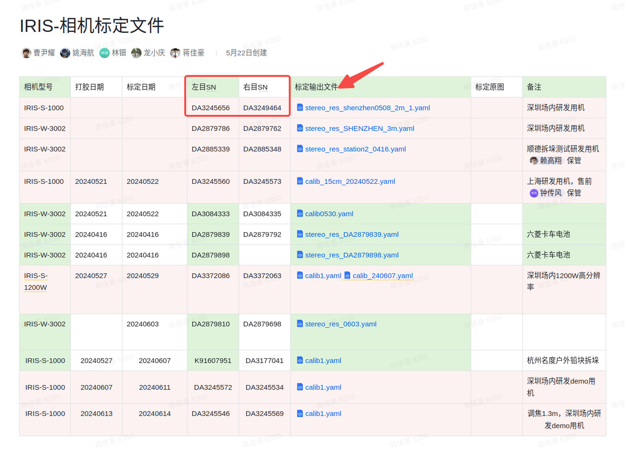
Find the corresponding Intrinsic/Extrinsic Parameter calibration file based on the Camera model and serial numbers(left and right SNs)at KINGFISHER-Camera Calibration Files, as shown below, and download the latest version of the calibration file.
If the corresponding calibration file cannot be found, contact the relevant personnel for confirmation.
Obtain the Camera Intrinsic/Extrinsic Parameter calibration files
Search for the Camera serial number recorded in step a at KINGFISHER-Camera Calibration Files
Compare the left and right SNs(serial numbers)and download the corresponding calibration file. PS: If the corresponding calibration file cannot be found, contact the relevant personnel for confirmation.

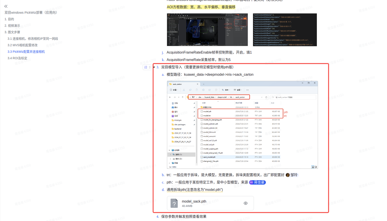
Binocular model import(using the pth version)
- Model Path:kuawei_data->deepmodel->iris->sack_carton,create it manually if this Path does not exist
trt:generally used for depalletizing. It is a large model and does not need to be replaced. Depalletizing-related configuration is completed at the factory.pth:source file
General depalletizing pth(rename it to "model.pth")
Configure the binocular model parameter
config.jsonIn versions after 1.4.2, put the
config.jsonfile together withmodel.pthinto thesack_cartonfolder, fill in the following content and modify it appropriately. Note:Themax_dispparameter needs special attention. Calculate it using the formula. If it is too large, it will introduce noise; if it is too small, disparity prediction errors will occur.max_dispmeans the maximum disparity. Calculate it once for the maximum working distance and once for the minimum distance, and take the larger value. Then check whether the calculated disparity is less than 256, 384, or 512, and fill in themax_dispparameter accordingly.Calculation formula: disp = baseline length * camera Intrinsic Parameter fx / distance from the object
Note: The baseline length is 0.15 for KingFisher-S-1000 and 0.40 for KingFisher-W-3002.
For low resolution, fx is generally around 1275; for high resolution, it is approximately 3000*scale according to the scaling ratio.
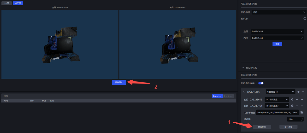
Save the Parameters and trigger capture to view the result
Note: Except for AOI, it is best to keep the left and right Camera Parameters consistent. When range requirements are not strict, AOI can also remain consistent. Check whether the left and right captured images are consistent in effect and style. If a color cast occurs, auto white balance may not have been turned off, or the Camera may have retained the values recorded before auto white balance was disabled. In that case, enter MVS again and re-enter the white balance ratio values.

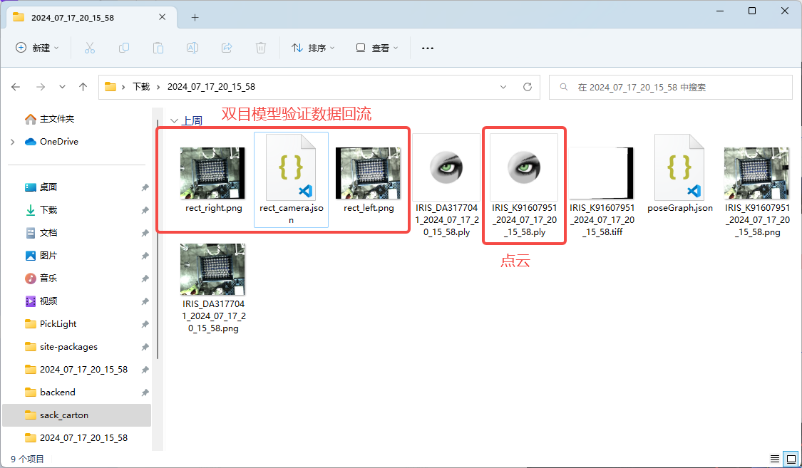
When binocular data verification is required on site, you can directly capture and save an image and then send the data from "Save Image".
Check whether the Camera is normal(whether Extrinsic Parameter correction is required)
This step is required; otherwise, image acquisition may fail.
After saving the image on the Camera interface, open the saved folder.
Find
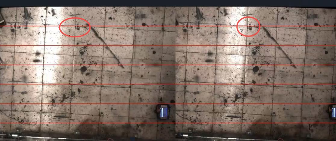
rect.bmpand check whether the red line passes through the same point in the left and right images. A normal result is shown below: the red line passes through the same point in the actual Scene in both images, proving that the Camera's Extrinsic Parameter is correct; otherwise, Extrinsic Parameter correction is required(for specific steps, refer to ROI and eye-hand calibration).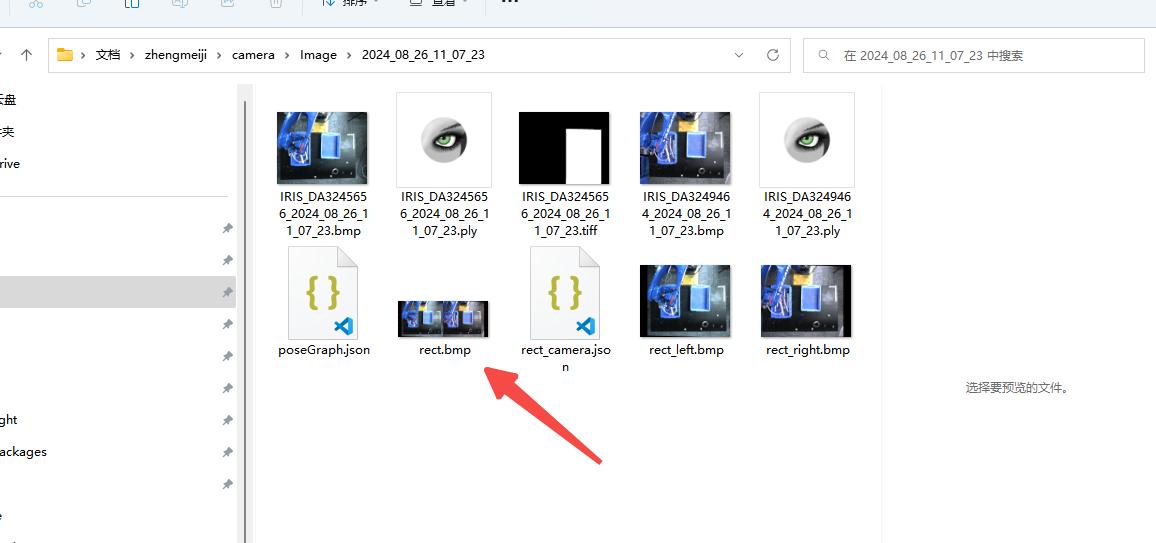
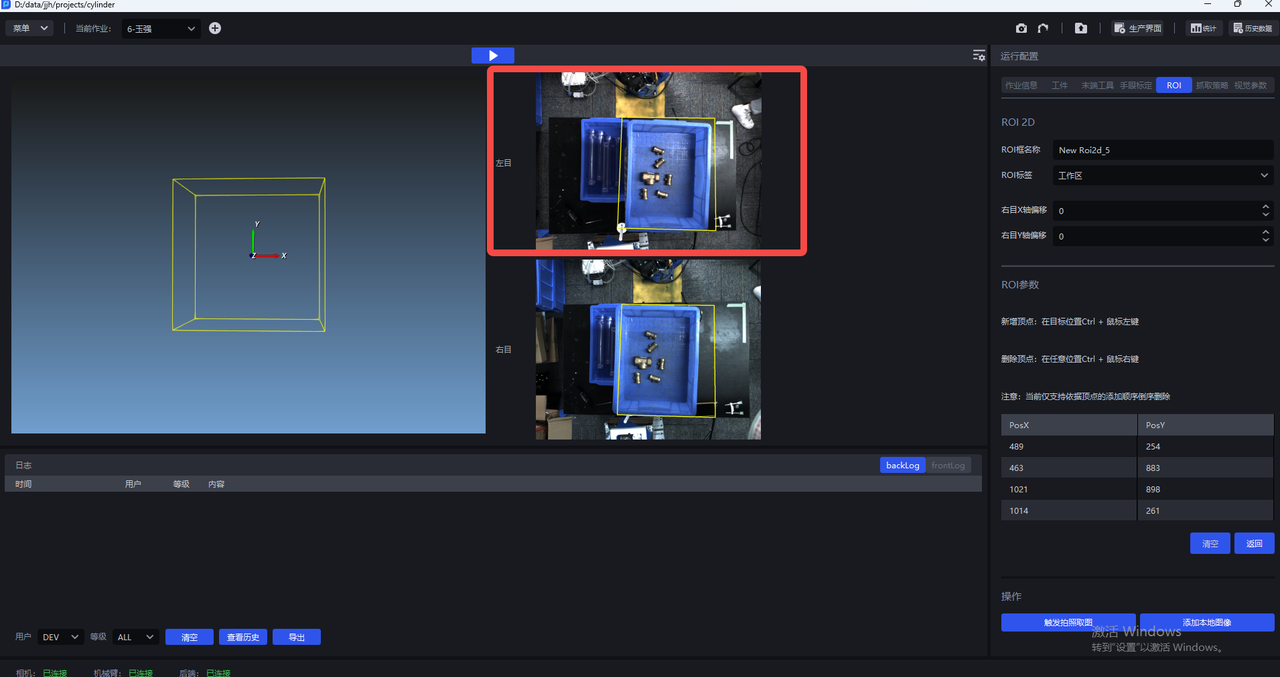
4.6 ROI
ROI settings
Recognition-oriented ROI2D is based on the left image(working area)
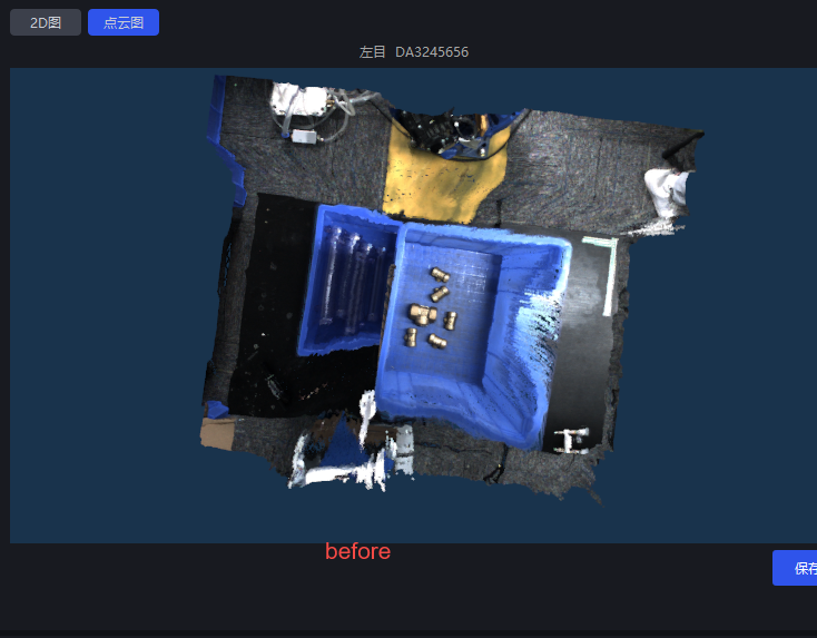
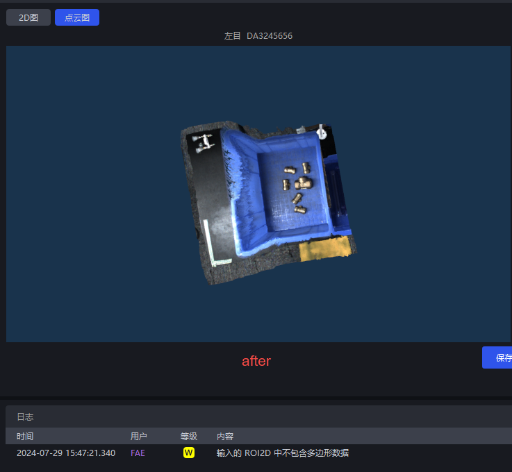
Point Cloud clipping ROI2D(observation area)
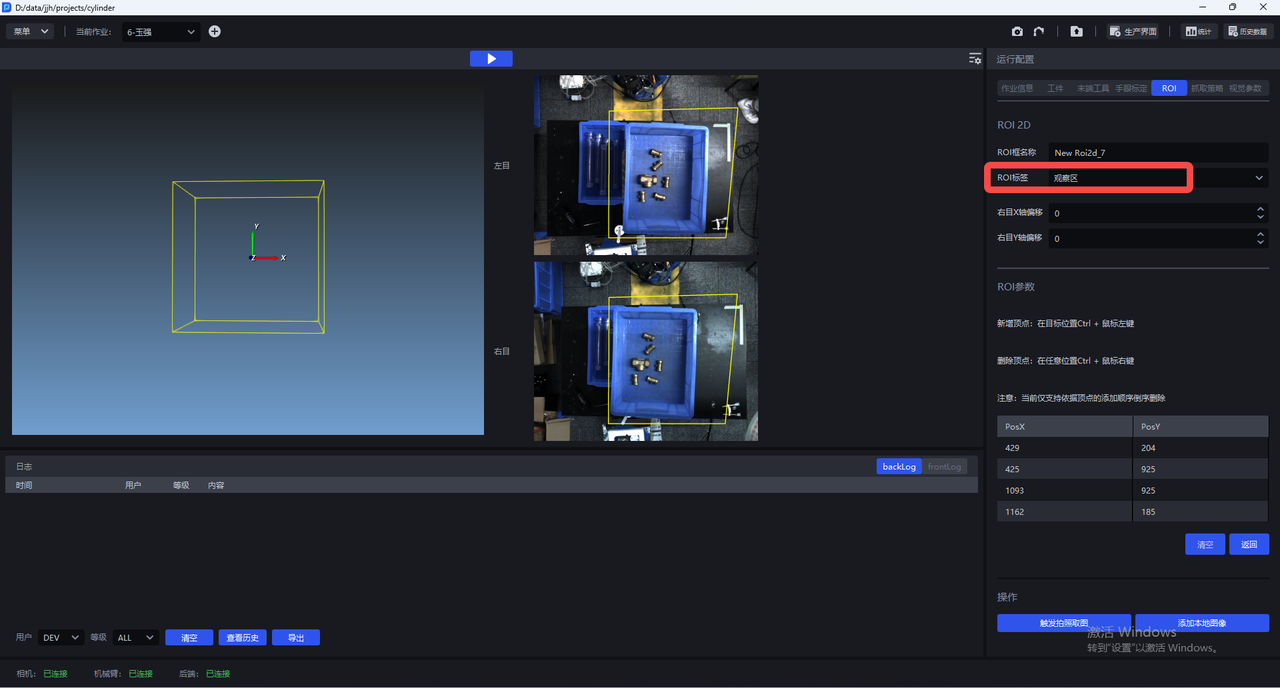
After the settings are completed, only the Point Cloud within the ROI range is generated, which can improve Takt Time and remove interference from other Point Clouds. PS: In some cases, Point Cloud quality may still fail to meet the standard after ROI is set, so this should be evaluated based on actual conditions.
4.7 Eye-Hand Calibration
For the Eye-Hand Calibration procedure, please refer to the relevant eye-hand calibration instructions.
After the Camera connection is completed, eye-hand calibration is required; otherwise, it will affect the image acquisition results.
Adjust the AOI properties in MVS to fixed exposure.
Follow the eye-hand calibration process for Camera image acquisition.
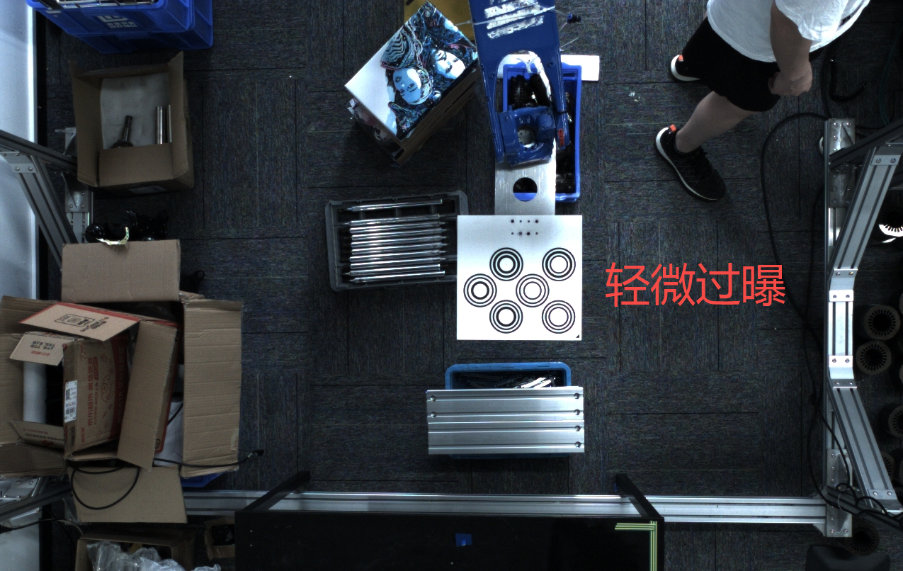
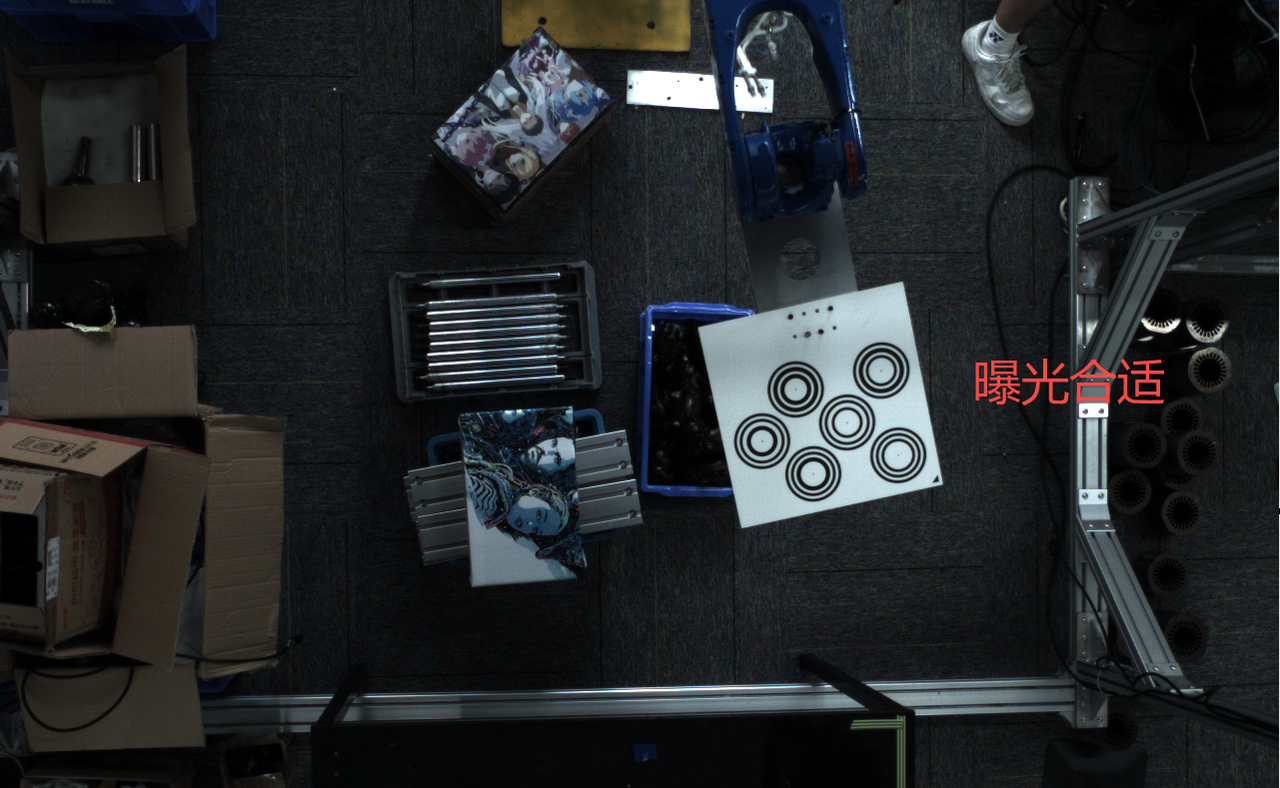
Adjust the image brightness so that the Calibration Board is not overexposed, as shown on the right below.
Extrinsic Parameter correction
If the calibration error appears small, but there are issues such as a large actual touch-point error or Point Cloud deformation, first rule out human operating factors, then check the red-line image obtained by saving the Camera capture to confirm whether the Camera structure changed during transportation. In that case, Intrinsic Parameter correction is required.
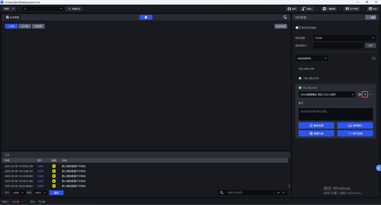
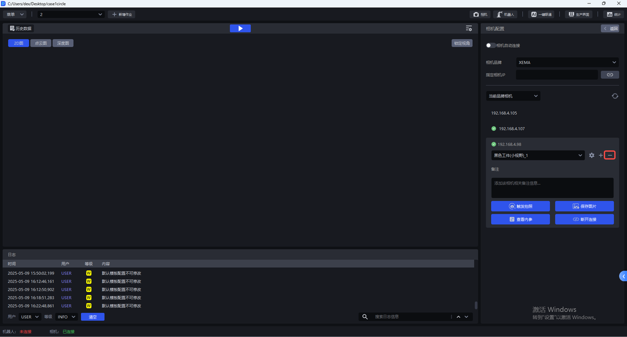
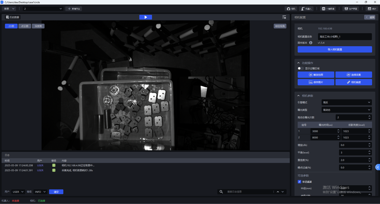
5. Camera Configuration
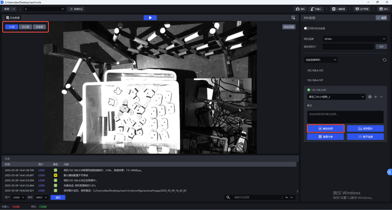
- Each Camera has multiple default configurations, and none of the default configurations can be changed. Select the corresponding default configuration, click
Trigger Capture, and use the Camera Parameters to capture a 2D image, Point Cloud, and Depth Map. You can view the imaging quality in the visualization window on the left.
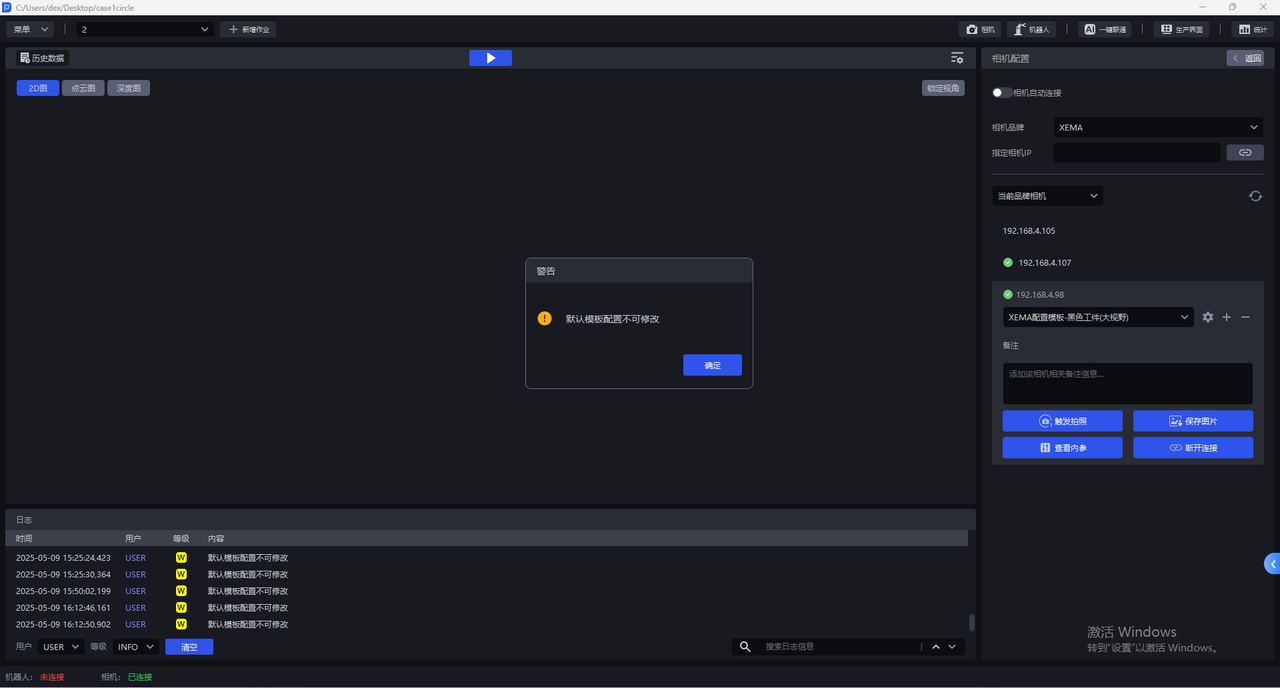

- The Camera's default configurations cannot be changed. If the 2D images captured by all default configurations cannot reach normal exposure, click
+to copy the current default Camera configuration, add an identical Camera configuration, and then enter the Camera configuration interface to modify the Parameters.
After copying the current default Camera configuration, you can switch to the newly added Camera configuration and click the settings button to enter the Camera configuration interface and modify the Parameters.
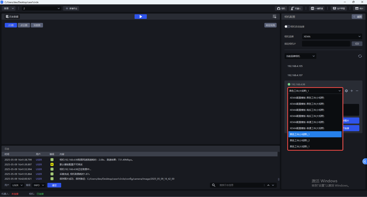

Click — to delete the newly added camera configuration.
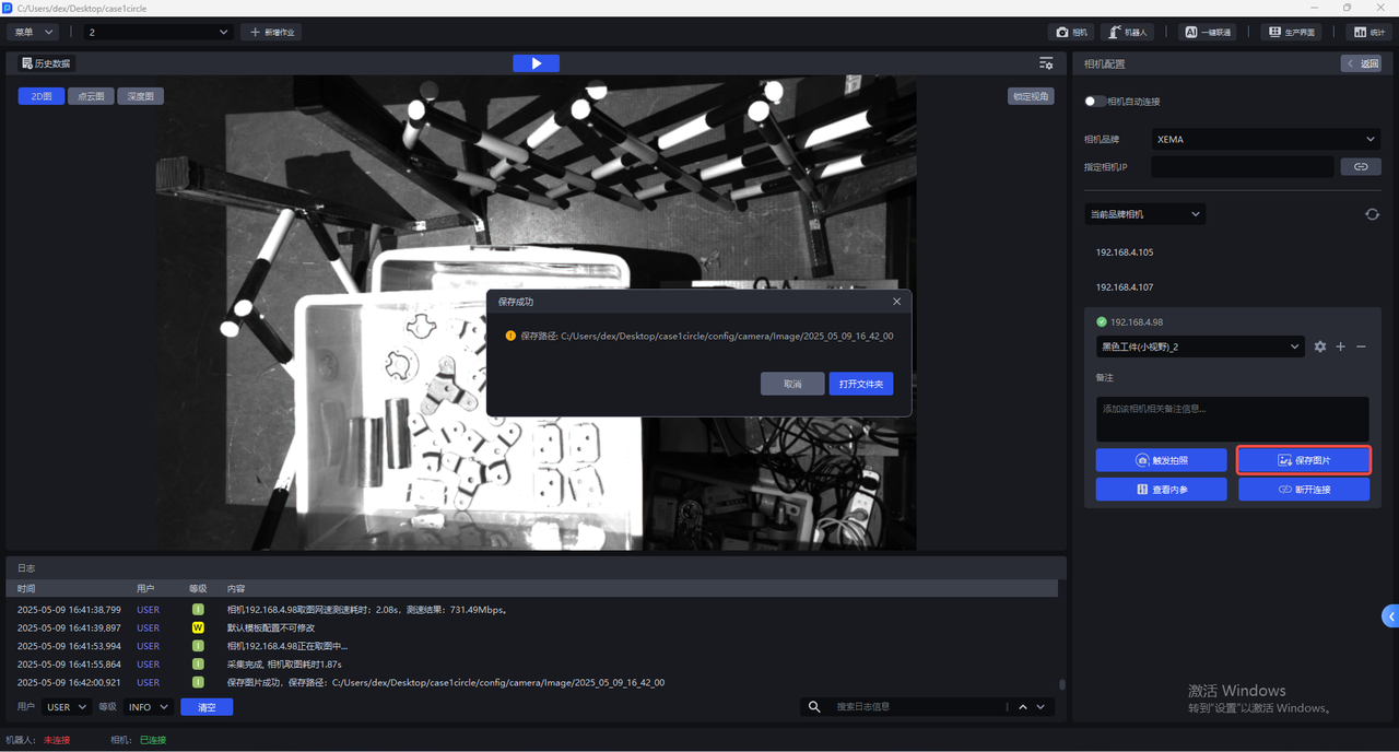
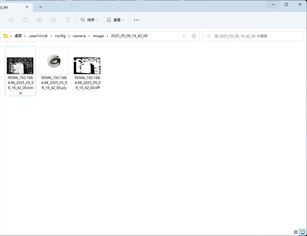
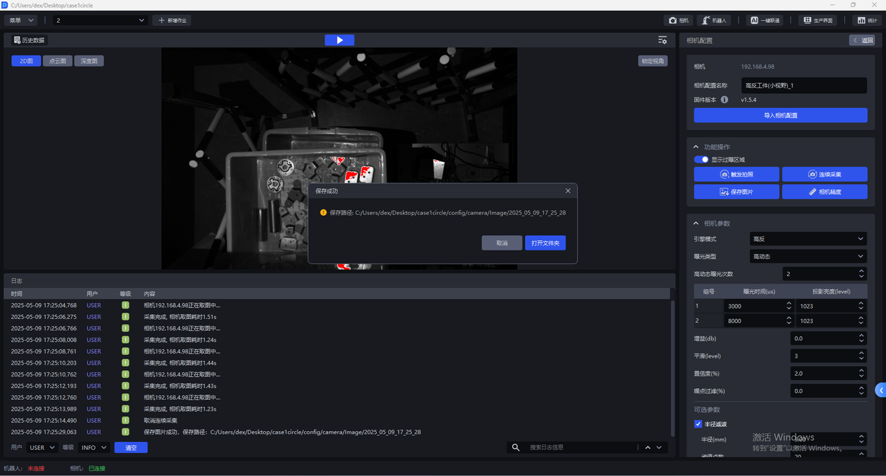
- Click
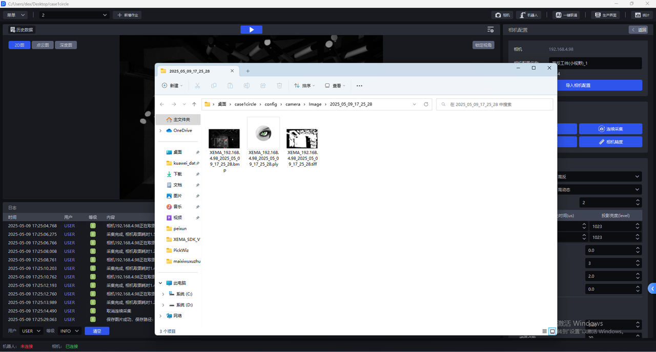
Save Imageto save the 2D image, Point Cloud, and Depth Map captured with the current configuration to the local machine, as shown below. The save Path is Project folder/config/camera/image/capture time. Files with thebmpsuffix are 2D images, files with theplysuffix are Point Clouds, and files with thetiffsuffix are Depth Maps.
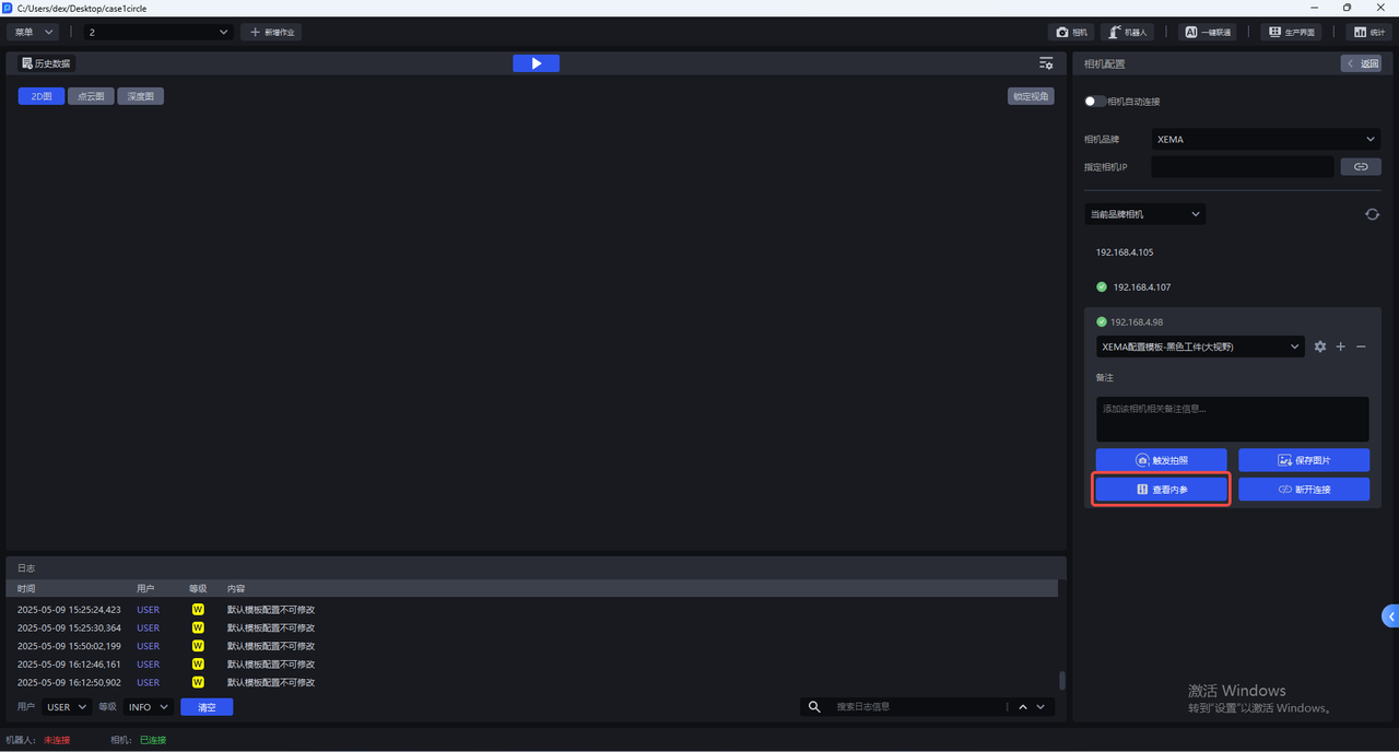
- Click
View Intrinsicsto view the Camera Intrinsic Parameter, including lens focal length, principal point coordinates, distortion coefficients, etc.
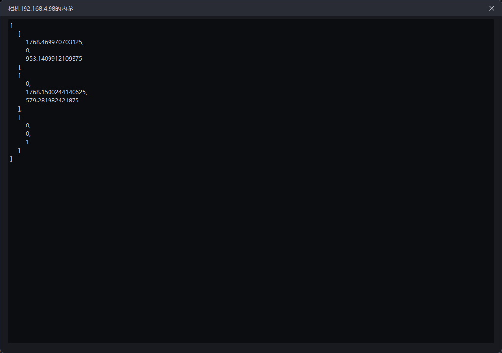
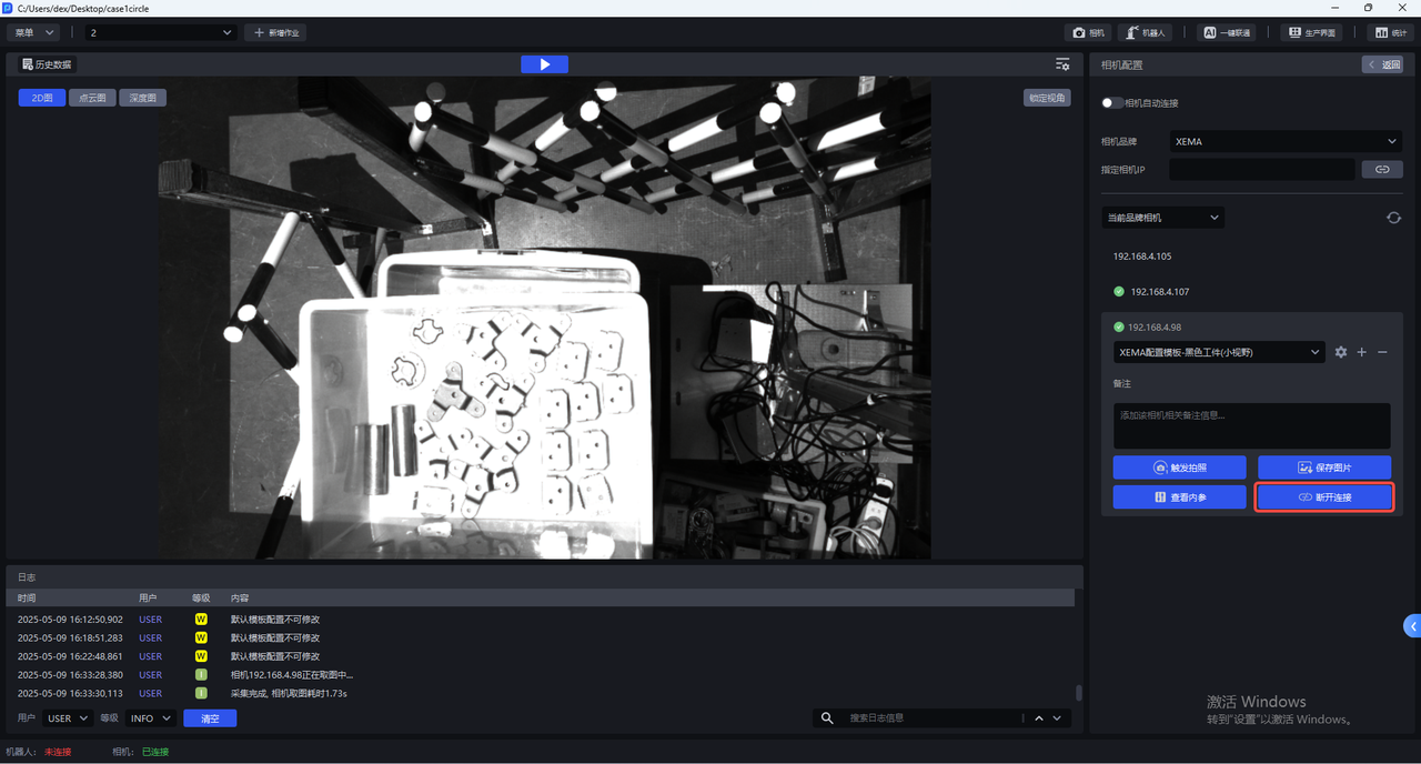
- Click
Disconnectto disconnect the Camera and select a Camera to reconnect.
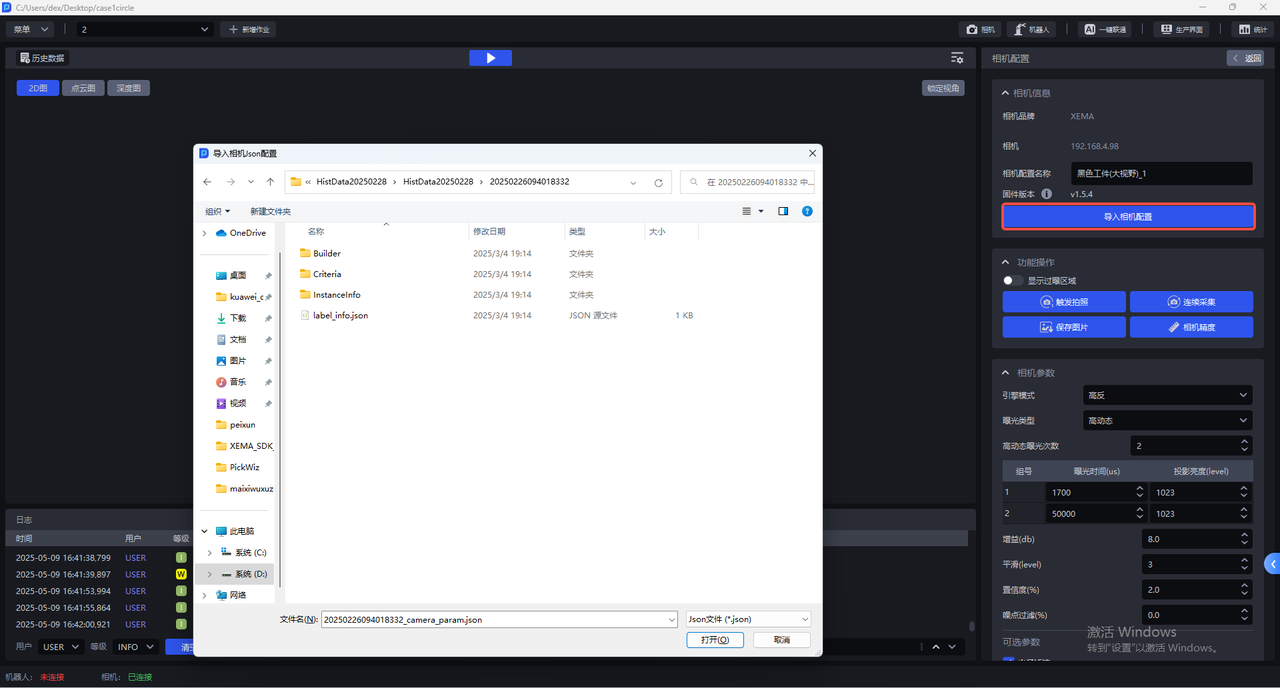
5.1 Import Camera Configuration
Enter the Camera configuration interface and click Import Camera Configuration to import an existing Camera configuration into the Camera.
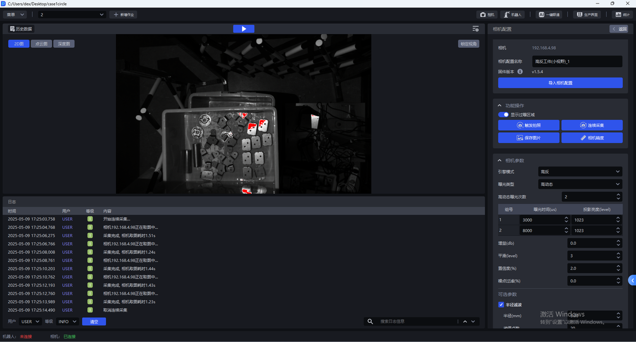
5.2 Functional Operations
The Camera configuration interface provides the following operations:
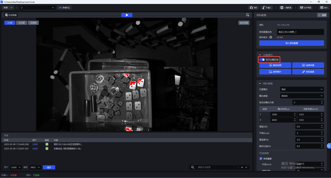
- Show Overexposed Areas
After enabling Show Overexposed Areas, the visualization window will display the overexposed areas of the current image, as shown below.
- Trigger Capture
Click Trigger Capture, and use the current Camera configuration to capture a 2D image, Point Cloud, and Depth Map. You can view the imaging quality of the current Camera configuration in the visualization window.


- Continuous Acquisition
Click Continuous Acquisition, and the Camera will continue taking pictures. Click Stop Acquisition to stop.
- Save Image
Click Save Image to save the captured 2D image, Point Cloud, and Depth Map.
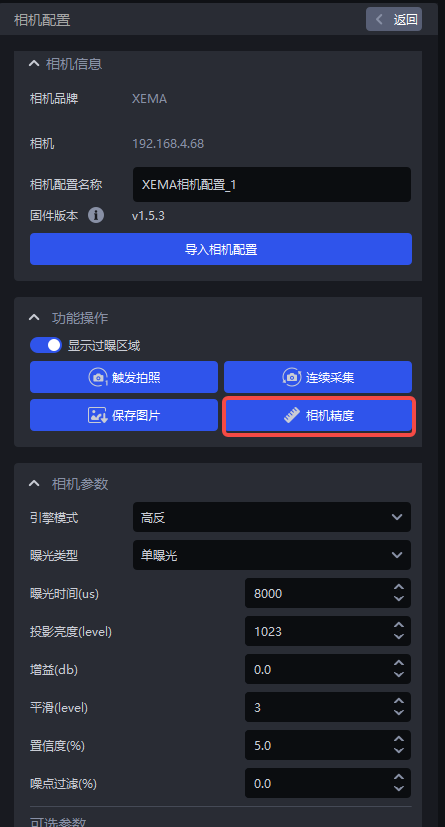
- Camera Accuracy
Click Camera Accuracy to view and verify Camera accuracy.
5.3 Camera Accuracy
5.3.1 View Camera Accuracy
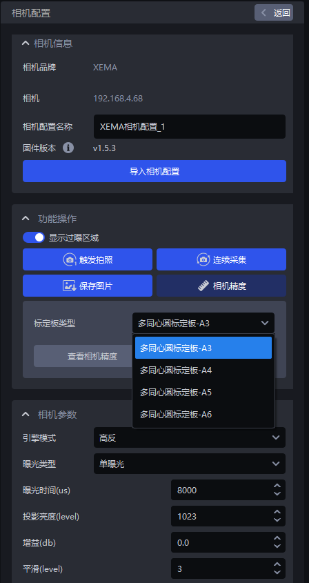
- Place the Calibration Board within the Camera's field of view. In the Camera configuration interface, click
Camera Accuracyto open the Camera accuracy interface, as shown below.
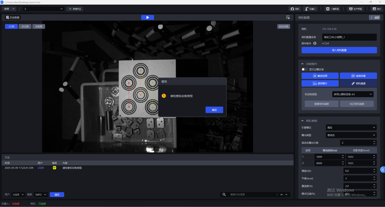
- Select the corresponding Calibration Board. If the selected Calibration Board does not match the actual one, a warning dialog saying "Please check the Calibration Board type" will pop up, as shown below. The warning appears when the Calibration Board type is A3.

- After selecting the correct Calibration Board type, click
View Camera Accuracy. PickWiz will automatically calculate the current Camera accuracy. If the Camera accuracy meets the requirement, only adjust the Parameters used for camera imaging quality adjustment; if the Camera accuracy is too large, a prompt saying "The error is too large. Camera accuracy calibration is recommended" will pop up.
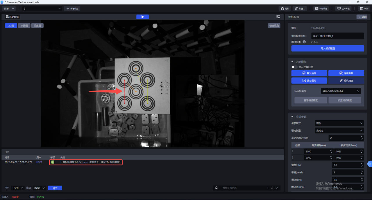
Camera accuracy below Xmm for each series indicates that the accuracy meets the requirement.
XEMA-D:0.2mm
XEMA-S:0.2mm
XEMA-L:0.5mm
5.3.2 Calibrate Camera Accuracy
During actual Camera use, and after Extrinsic Parameter calibration, the current Camera accuracy must be verified to determine whether it meets the requirements.
When viewing Camera accuracy, if the Camera accuracy error is abnormal, the Camera accuracy should be calibrated.
If the Point Cloud captured by the current Camera shows large fluctuations, the Camera accuracy should be calibrated.
Before calibrating Camera accuracy, enable
Show Overexposed Areasto check the exposure level of camera imaging. If there are overexposed areas, adjust the exposure time of the single exposure to ensure normal camera imaging exposure.After calibration is complete, switch the Parameters used for camera imaging quality adjustment back to the original configuration.
- In the Camera configuration interface, click
Camera Accuracy.

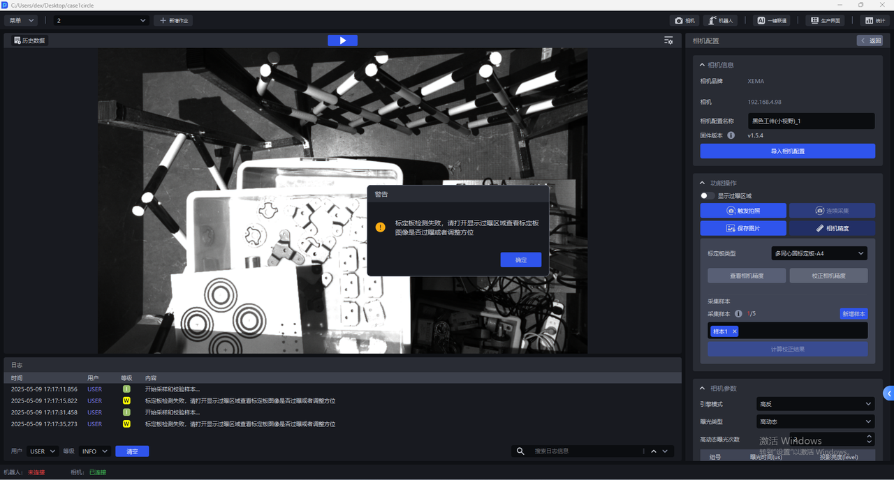
- Select the corresponding Calibration Board. If the selected Calibration Board does not match the actual one, a warning dialog saying "Please check the Calibration Board type" will pop up, as shown below. The warning appears when the Calibration Board type is A3.

- After selecting the correct Calibration Board type, click
Calibrate Camera Accuracy.
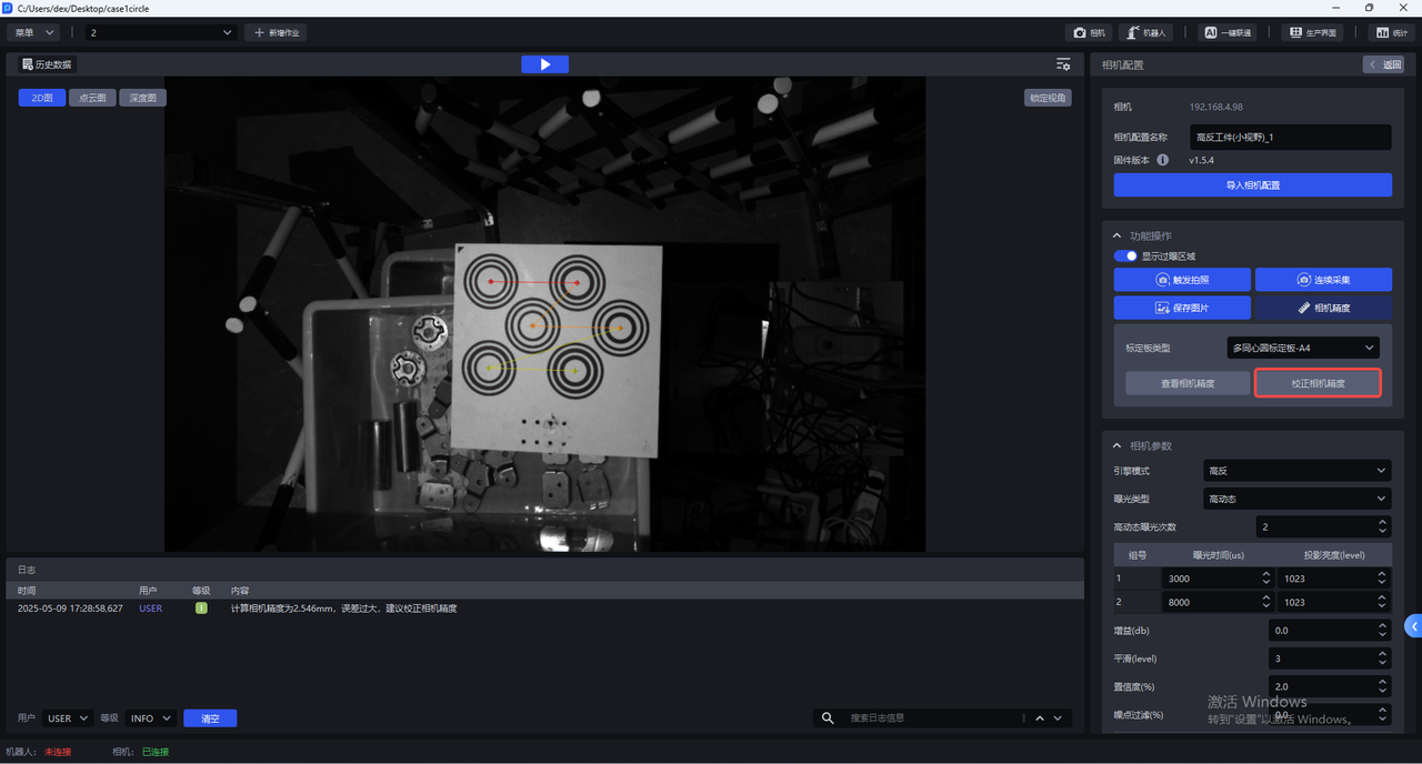
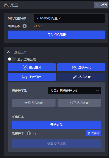
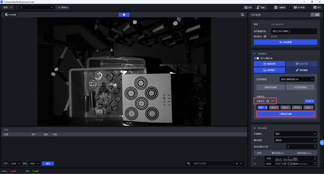
- Place the Calibration Board horizontally in the center of the Camera's field of view, then click
Add Sample. The Camera starts sampling and validating the sample. If the collected sample passes validation, it will be added belowCollected Samples, as shown below.
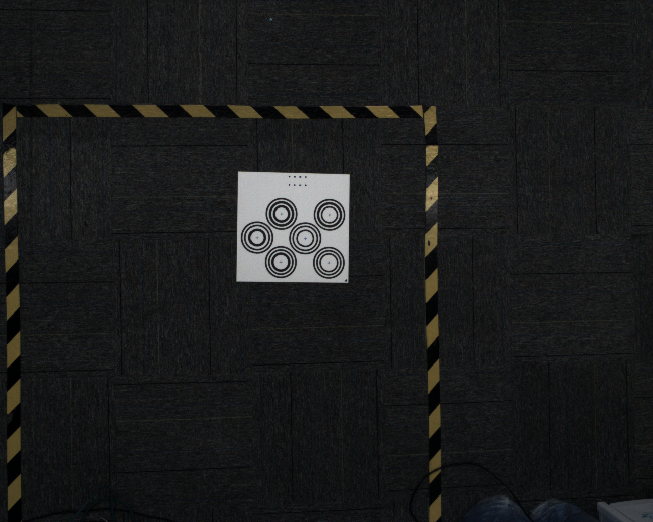
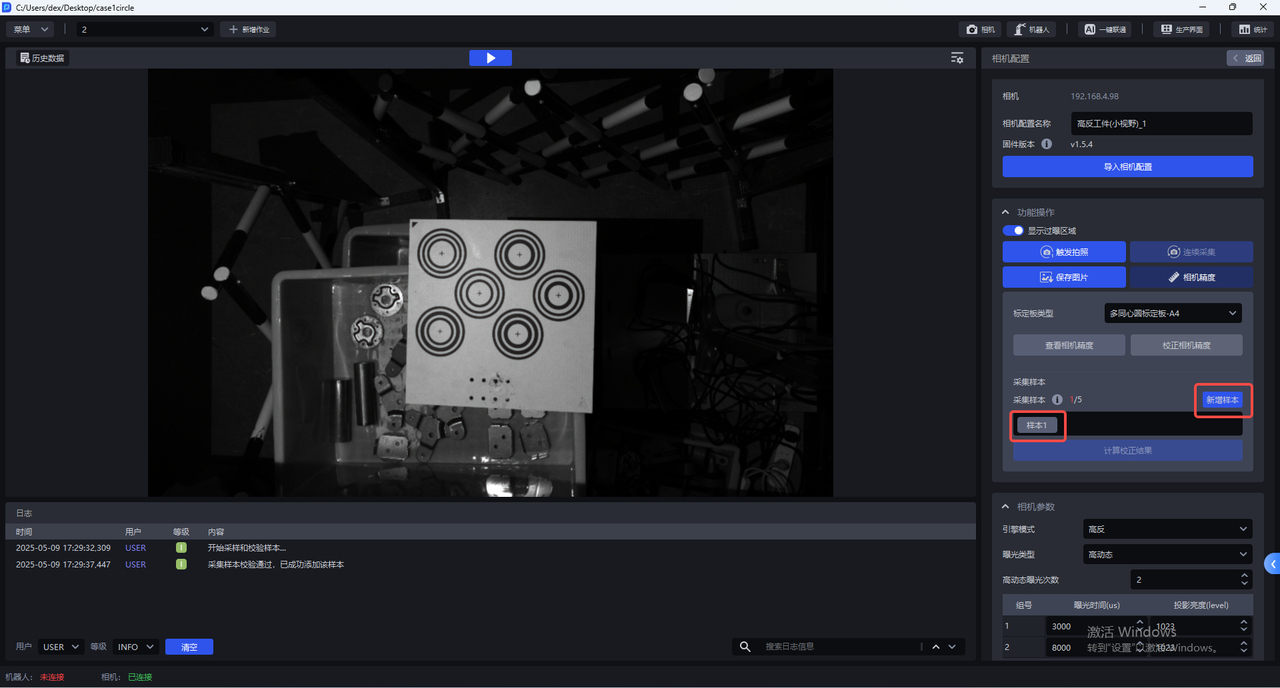
Click Sample x to view the collected sample. The centers of all concentric circles on the Calibration Board in a validated sample turn green.

- Move the Calibration Board to the four corners within the Camera's field of view and add samples.
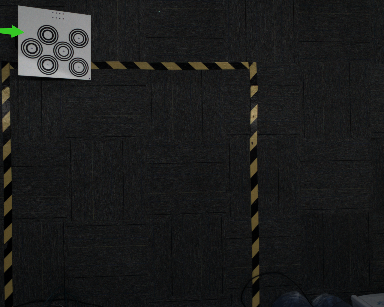
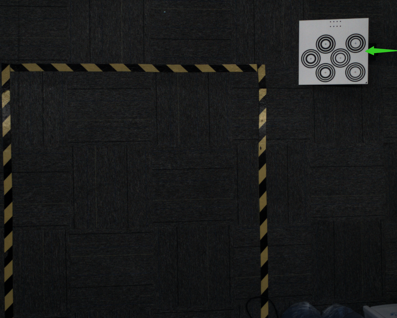
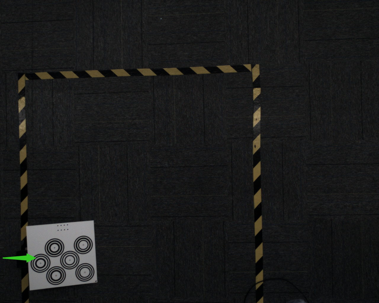
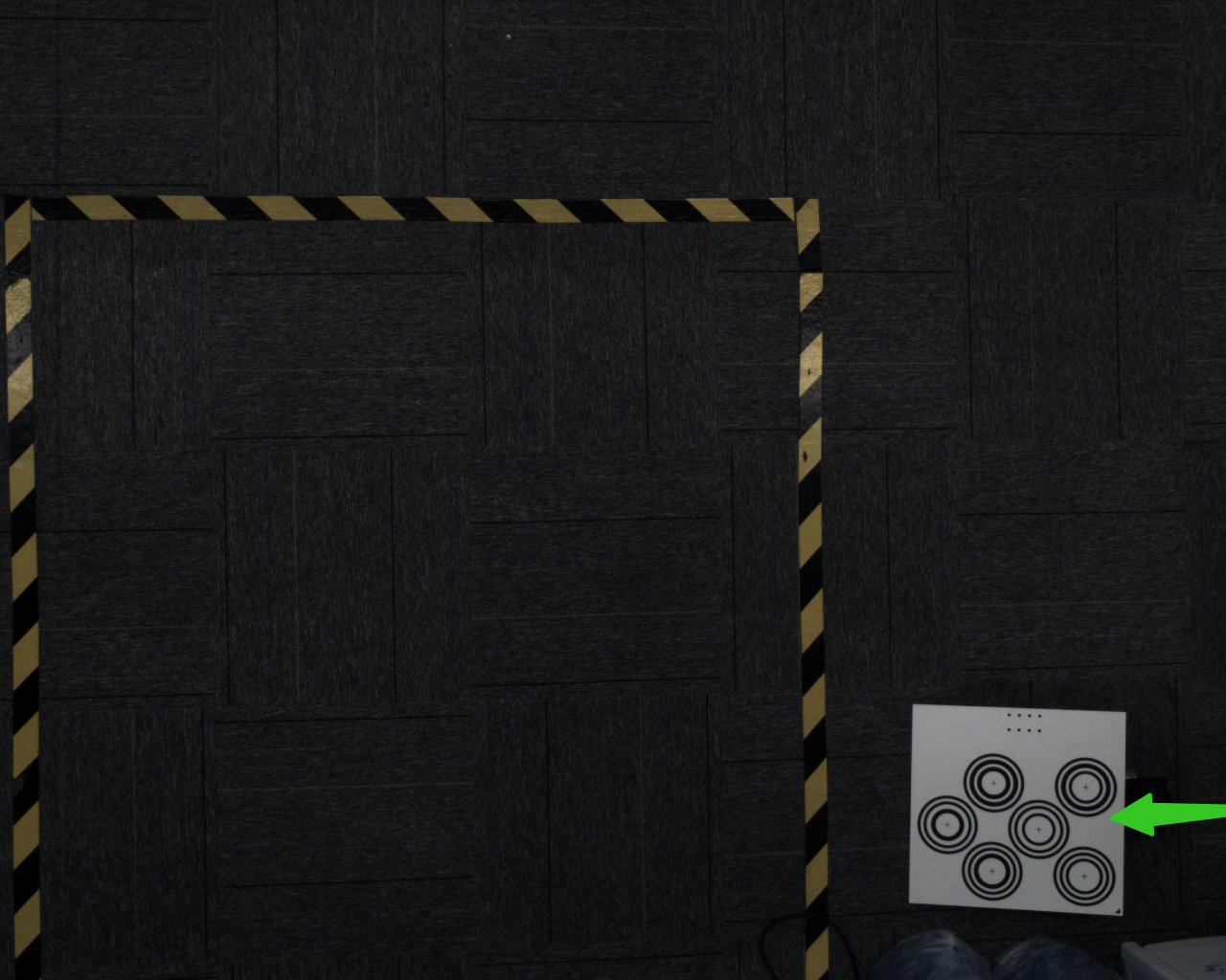
At each corner, prop up the Calibration Board at an angle. The placement angle of the Calibration Board should be 15-30°; the tilt angle should be neither too large nor too small.
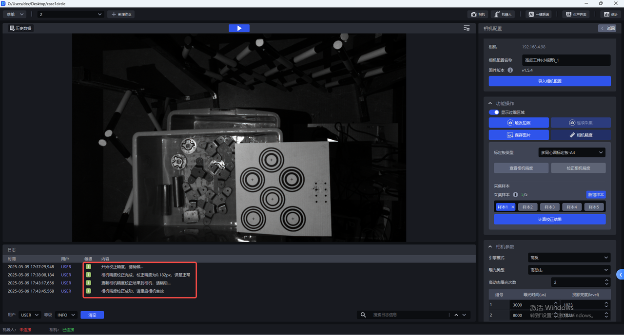
- After adding 5 samples, click
Calculate Calibration Results.
- After calibration is complete, a prompt saying "Camera accuracy calibration completed. The calibrated accuracy is x, the error is normal. Do you want to overwrite the current camera parameter configuration?" will pop up.
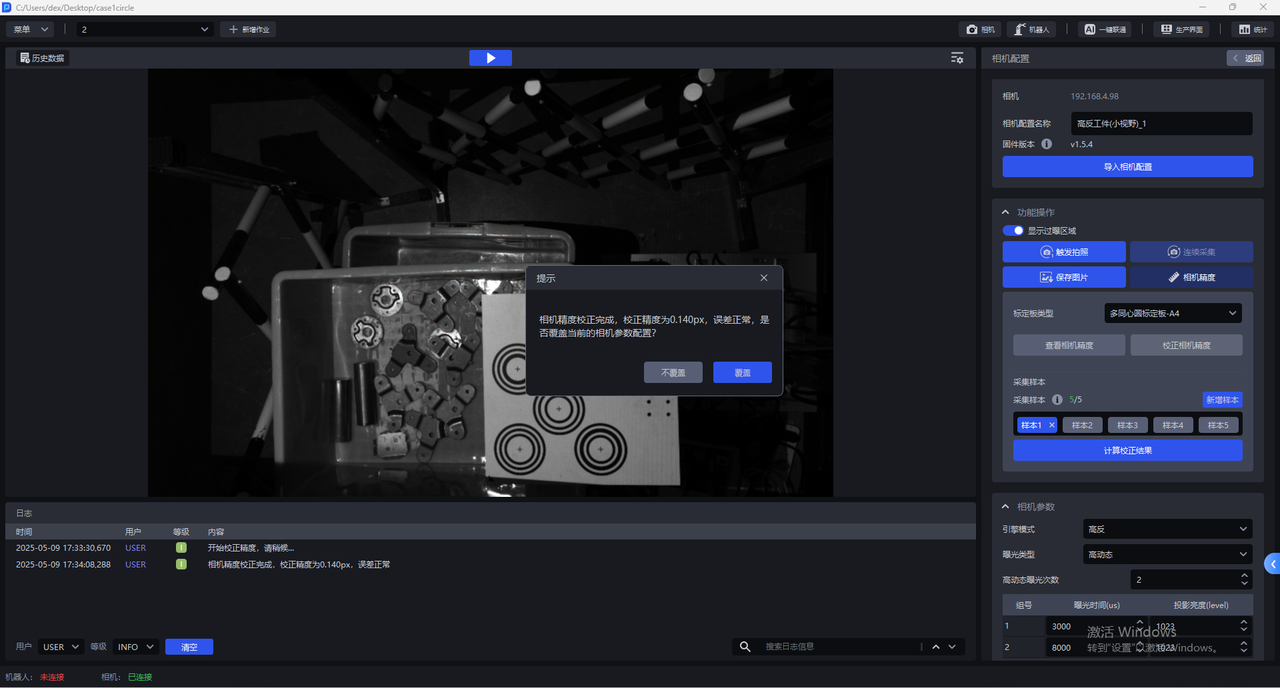
If you choose to overwrite the current camera parameter configuration, the Camera accuracy calibration result will be updated to the Camera, and a Camera restart is required for it to take effect.
6. Camera Imaging Quality Adjustment
The binocular Camera consists of two 2D Cameras. Deep Learning model segmentation and recognition are based on the left image, which is preprocessed and then input into the Deep Learning model.
6.1 Required Parameters
6.1.1 Engine Mode
Engine modes include Normal, Highly Reflective, and Black. Among them, Highly Reflective mode is excellent for highly reflective parts, Black mode is excellent for black workpieces, and Normal mode can handle ordinary workpieces.
| Engine Mode | Description |
|---|---|
| Normal | Suitable for general workpieces |
| Highly Reflective | Suitable for highly reflective workpieces |
| Black | Suitable for black workpieces |
6.1.2 Exposure Type
(1)Single Exposure
Single exposure can be used for workpieces with ordinary textures.
(2)High Dynamic Range:
For highly reflective workpieces, the HDR function can be used for Point Cloud fusion.
The High Dynamic setting of the exposure type should be used together with the High Dynamic setting of the engine mode.
High Dynamic Range Imaging (HDRI or HDR for short) is a set of techniques used to achieve a larger exposure dynamic range (that is, greater differences between light and dark) than ordinary digital imaging technology.
High dynamic range makes image layers more distinct and the contrast between light and dark more obvious (especially when dealing with reflective workpieces).
Parameter tuning recommendation:
- When using high dynamic range, you can choose the number of high dynamic exposures according to the specific Scene and workpiece, with a value range of 2~6 and a default of 2. If the 3D Point Cloud quality and 2D image quality are poor, increase the number of groups to expose the object multiple times to achieve the best imaging quality.
It is recommended to use fewer high dynamic exposures while meeting Point Cloud quality requirements.
(3)Repeated Exposure: The number of times the Camera repeats shooting. Its function is to improve the signal-to-noise ratio. The higher the signal-to-noise ratio, the better, because random noise will be suppressed and effective information will increase. The value range is 0~10.
Repeated exposure can be used for black objects to optimize the Point Cloud through multiple exposures.
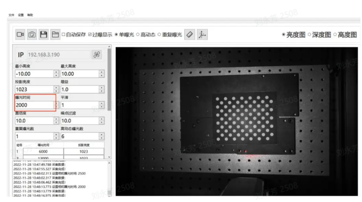
6.1.3 Exposure Time
Camera exposure time: Exposure time is the time for which the shutter remains open while reflected light from the Scene passes through the lens and reaches the imaging photosensitive material. The longer the exposure time, the more light enters. If the exposure time is too long, overexposure will occur, which affects the Point Cloud, so adjust it according to actual conditions.
Range: 1700-100000
Exposure time and projection brightness form a group. One high dynamic exposure count is one group. Set appropriate exposure time and projection brightness values for each group.
Exposure time: Exposure time is the duration for which light enters the Camera while the shutter is open. The longer the exposure time, the more light enters and the clearer the image becomes.
If the exposure time is too long, overexposure will occur. You can enable the overexposed area display; the red parts indicate overexposed areas.
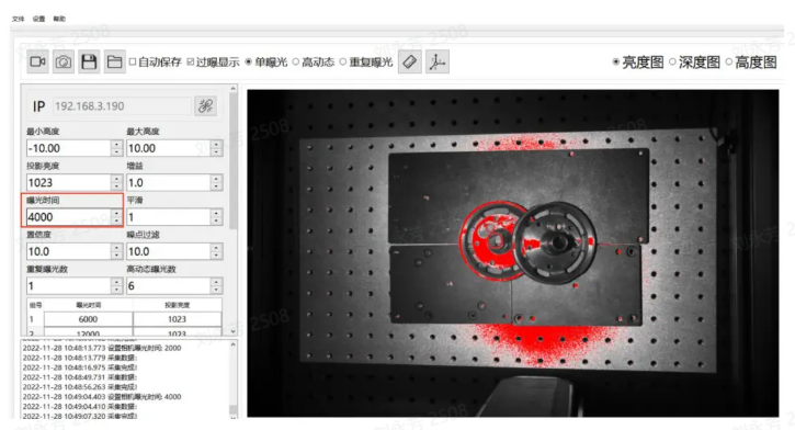
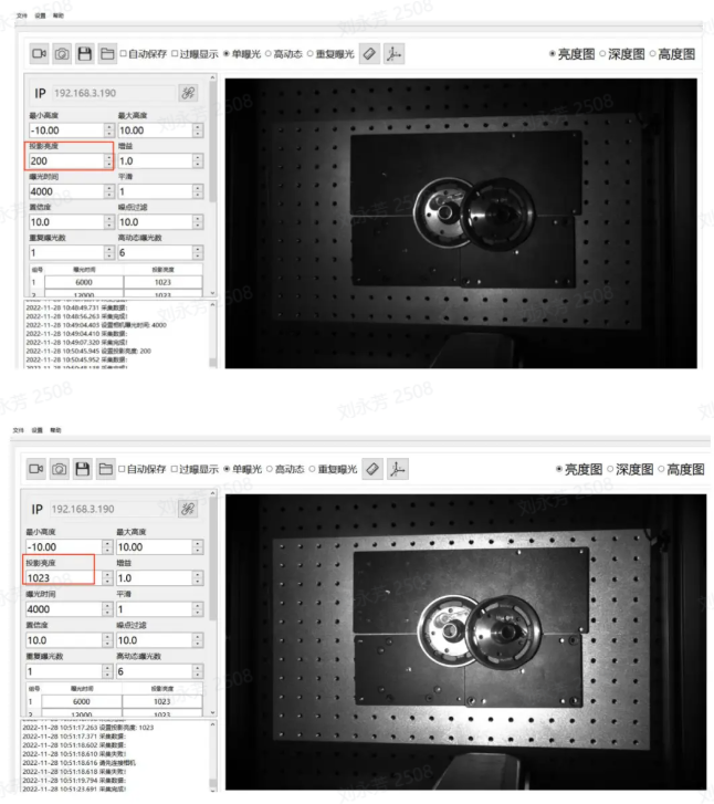
6.1.4 Projection Brightness
Projection brightness refers to the intensity of the projected light. The greater the light intensity, the brighter and clearer the image. Within a certain range, the human eye may perceive the image as clearer because of the higher brightness. If it exceeds this limit, excessive brightness will make the image impossible to see clearly.
Range: 0-1023
The larger this value, the greater the projection brightness, which can effectively improve the signal-to-noise ratio. It is recommended to use the maximum value. Only consider reducing this value if the exposure time is adjusted to the minimum and overexposure still occurs.
Note: It is recommended to set the brightness to 1023

6.1.5 Gain
Adjusts the brightness of the image.
Range: 0-24
The gain value of the 2D Camera can be adjusted and should be increased appropriately. As gain increases, noise will also increase.
6.1.6 Smoothing
Range:0-5
Performs smoothing on the Point Cloud.
6.1.7 Confidence
Confidence indicates the level of reliability and is used for an initial screening of the Point Cloud. Generally, 2-5 is sufficient, and customers can adjust it according to site conditions.
Lowering the Confidence preserves more black regions in the Depth Map; conversely, increasing the Confidence removes black noise in the Depth Map.
Range: 0-100

6.1.8 Noise Filtering
In machine vision application scenarios, when inspecting objects such as metal surfaces, aluminum foil surfaces, reflective films, and smooth surfaces, specular reflection may cause excessively strong local reflected light, resulting in the loss of the object's original information and interfering with machine vision inspection. Noise filtering can remove the generated noise while preserving the original information of the object.
Range: 0-100
When recognizing objects such as metal surfaces, aluminum foil surfaces, reflective films, and smooth surfaces, specular reflection may cause excessively strong local reflected light, causing the loss of the object's original information and interfering with PickWiz recognition and image inspection. Increasing the noise filtering value can remove the generated noise while preserving the original information of the object.

6.2 Optional Parameters
6.2.1 Radius Filtering
For each point in the Point Cloud, define a sphere with radius r and count the number of valid points. If the number of points inside is less than the valid-point threshold, it is considered a noise point and removed. The smaller the radius and the larger the valid-point threshold, the more obvious the filtering effect.
Radius range: 0-99
Valid point range: 0-99
6.2.2 Depth Filtering
Filters floating noise points in the Z-axis direction. The larger the threshold, the more obvious the filtering effect. For filtering methods based on the Depth Map, a threshold of 33 is recommended at a distance of 1000mm.
Range: 0-100
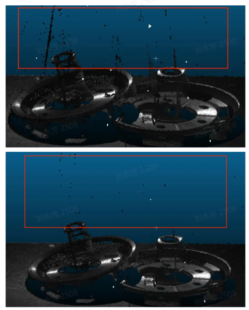
6.2.3 Reflection Filtering
Filters vertical-surface noise caused by mutual reflection of metals. The larger the threshold, the more obvious the filtering effect.
Range: 0-100
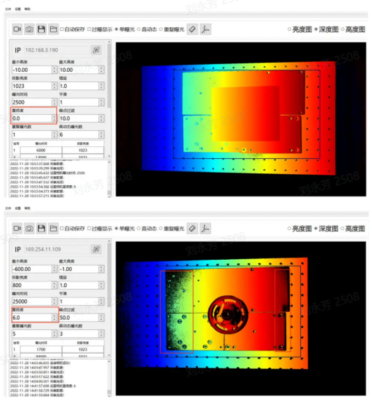
6.2.4 Phase Correction
Phase correction, that is, Point Cloud grayscale compensation, is a method of correcting grayscale information in 3D Point Cloud data. The purpose of Point Cloud grayscale compensation is to eliminate these grayscale value differences and convert the grayscale information in the Point Cloud into values corresponding to the actual surface reflectance of the object. The larger the threshold, the more obvious the correction.
Range: 0-100
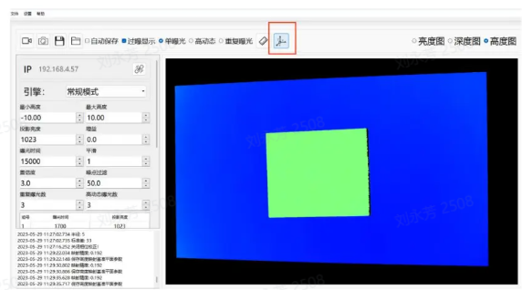
Usage: First place the Calibration Board and use the plane of the Calibration Board as the reference plane, as shown above.
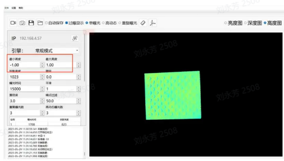
As described in the Maximum Height and Minimum Height section, set the maximum height to 1 and the minimum height to -1 so that only the Calibration Board part is displayed, as shown above.
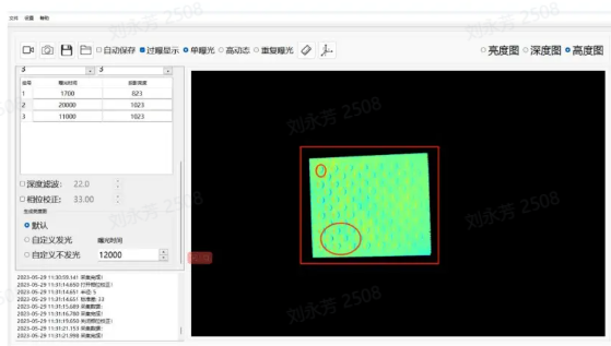
With phase correction disabled, the Calibration Board is shown as above. On the actual Calibration Board, the whole board is flat, and there is no vertical fluctuation between the circular and non-circular parts, but the actual captured result shows fluctuations in the circular areas.
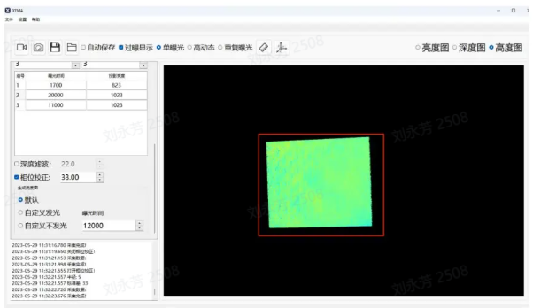
After enabling phase correction, if the Calibration Board shows basically no color difference or the difference is not obvious, the correction is successful.
6.2.5 2D Image Overlay Exposure
This function can separately override the original 2D image after the Point Cloud is obtained. Sometimes the Point Cloud is good but the 2D image is too dark or overexposed and does not meet requirements. In this case, you can enable 2D overlay exposure to override the original 2D image.
If you select illuminated, you can set the exposure time, gain, and capture method (single exposure or high dynamic) manually.
If you select non-illuminated, it refers to the ambient light brightness. You can also set the exposure time, gain, and capture method (single exposure or high dynamic) manually.
Overlay Gain
When using the 2D overlay exposure function, you can adjust this gain to make the image brighter.
Overlay Exposure Time
When using the 2D overlay exposure function, you can adjust this exposure time to make the image brighter.
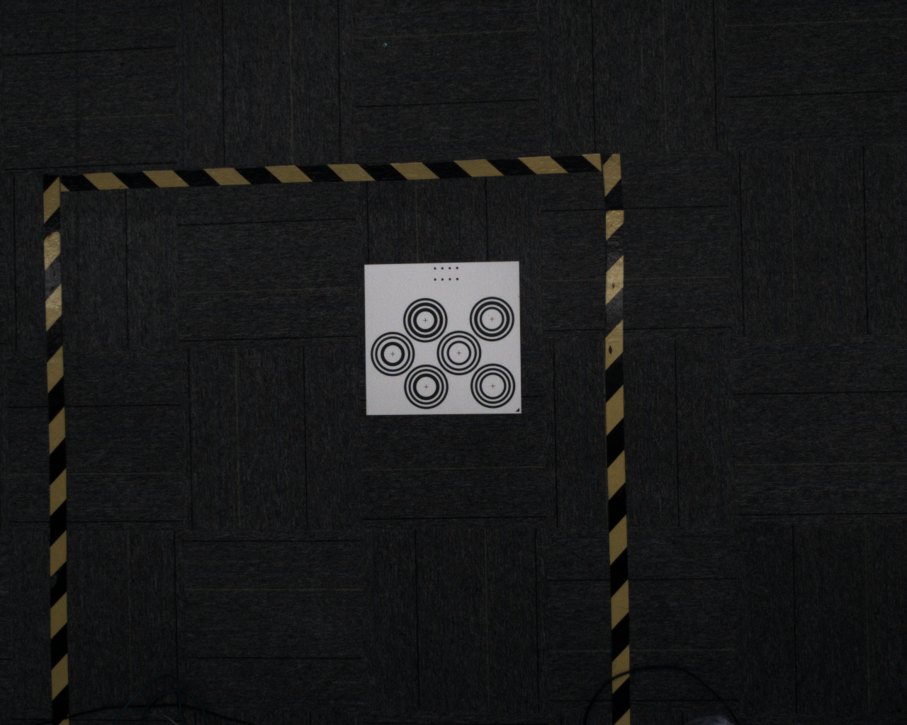
7. Typical Cases
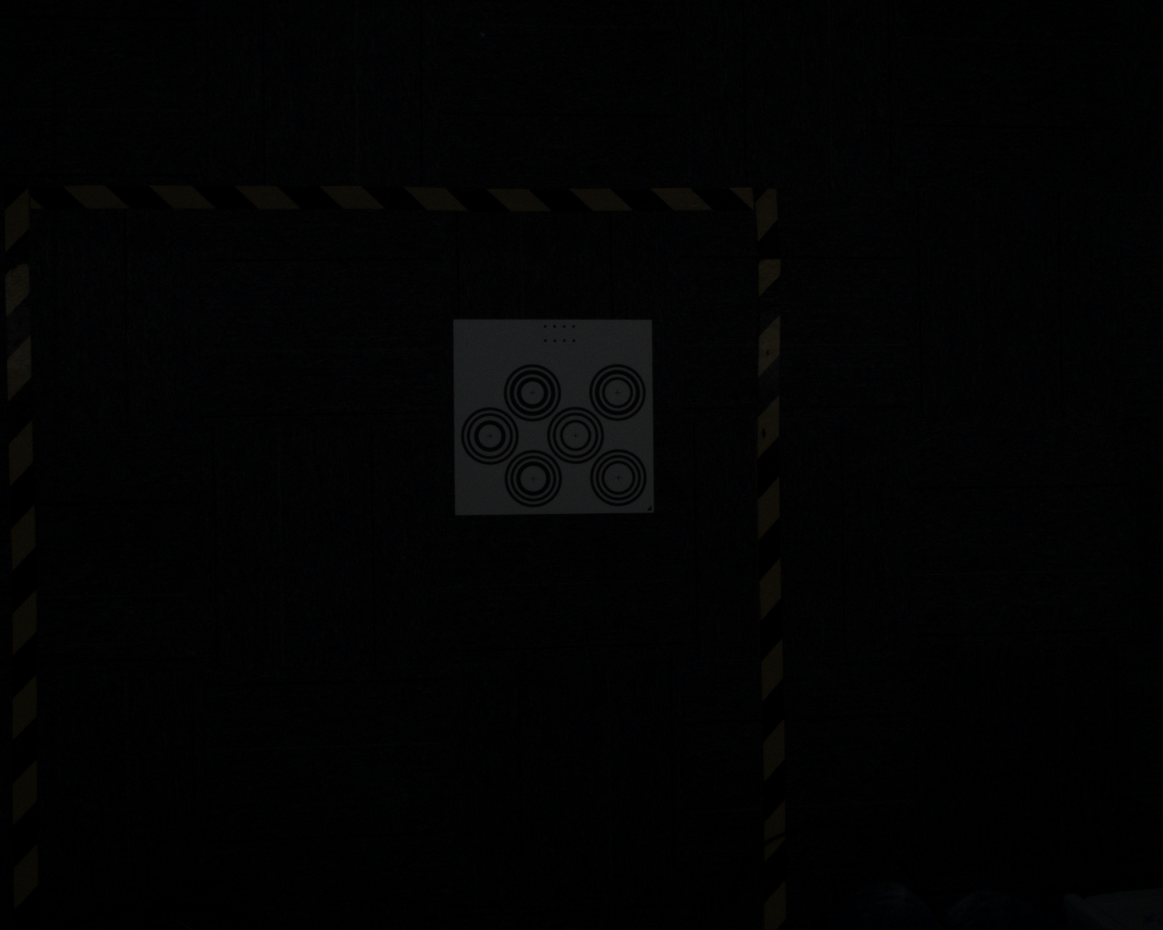
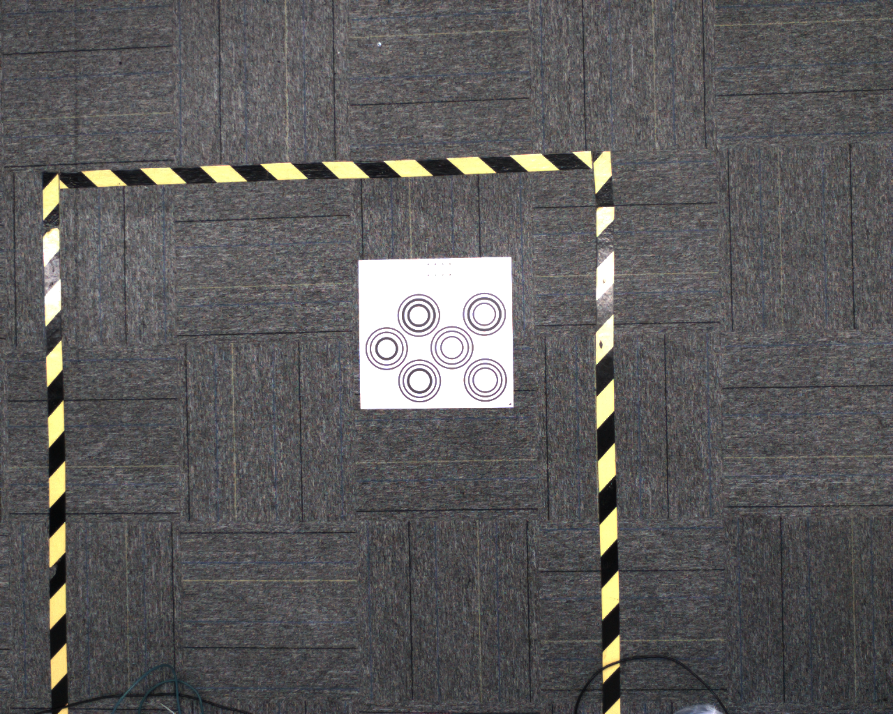
Camera imaging quality adjustment principle: keep the exposure on the workpiece surface uniform and the texture clearly visible. The following cases use 1024*1280 resolution as an example.
Case 1: Shanghai CIIF - Outdoor Sunlight Depalletizing
Scene characteristics: abrupt changes in ambient light, from indoor LED lighting to direct sunlight(the images below show the effect before and after adjustment)
Parameter tuning approach: After the abrupt ambient light change, keep imaging stable without changing Takt Time. Use Auto Exposure Mode 2(Hikrobot SDK built-in AOI auto exposure)and modify the AOI Parameters.
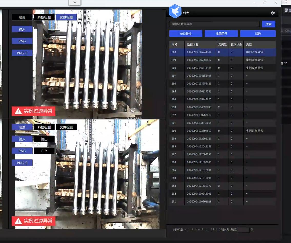
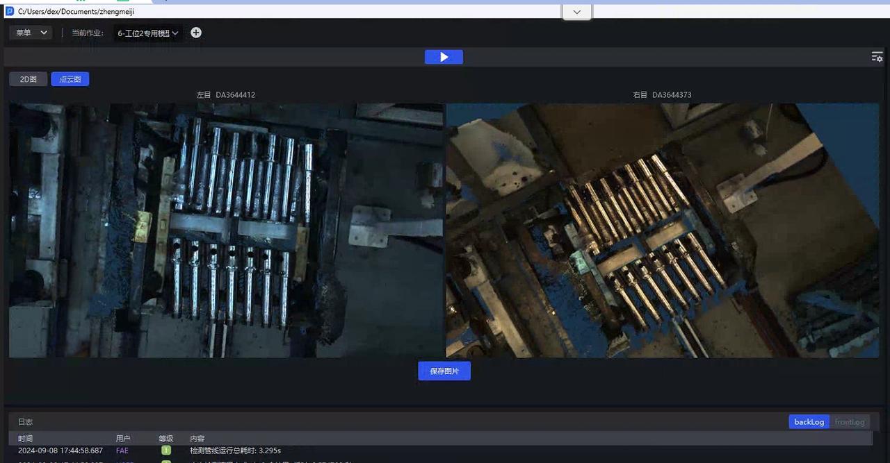
Case 2: Shanghai CIIF - Indoor Lighting with Highly Reflective Rod Stock
Scene characteristics: the color of the spotlight changes, but the brightness is nearly consistent
Parameter tuning approach: fixed exposure with a lower exposure value is sufficient.
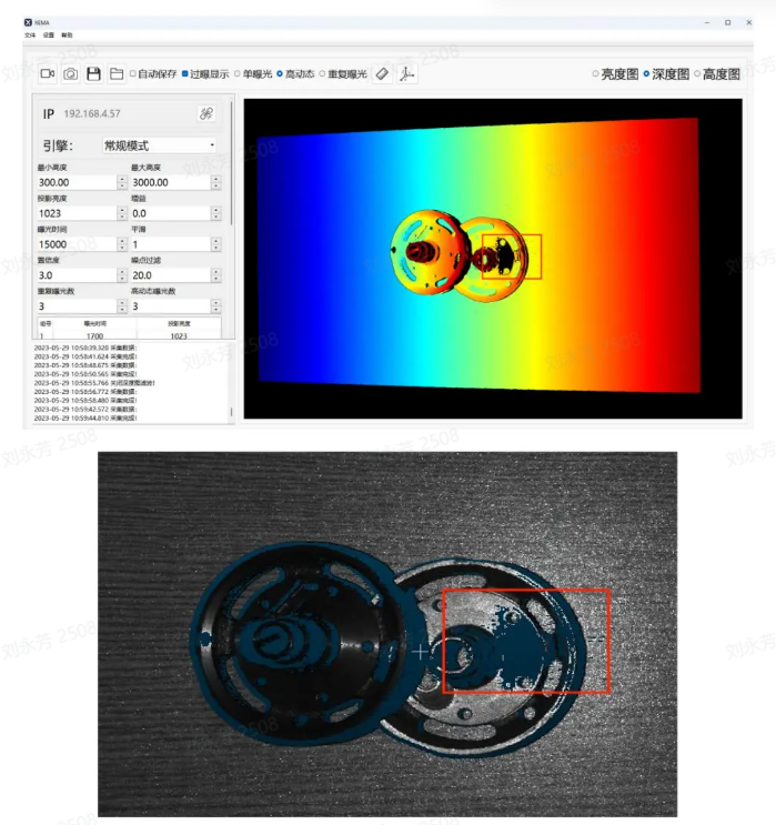
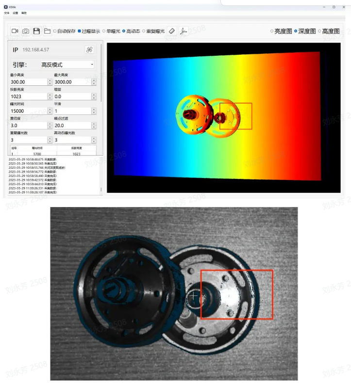
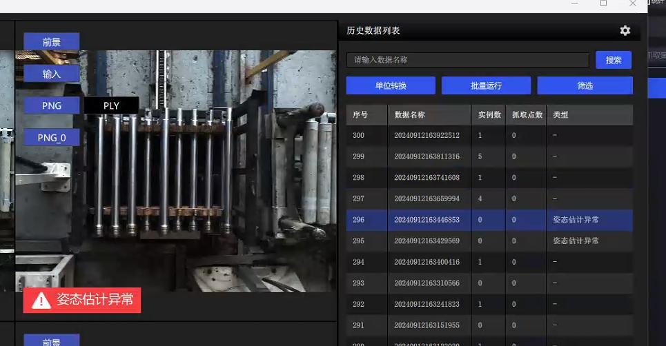
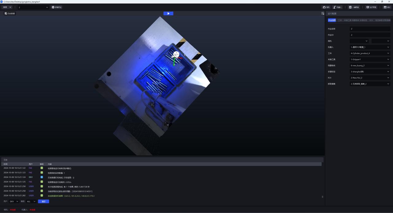
Case 3: Luyuan Cylinder - Semi-outdoor Sunlight Highly Reflective Workpieces
Scene characteristics: there is a skylight overhead, and daytime lighting intensity varies with the weather; supplemental lighting is needed at night(the images below show the effect after adjustment)
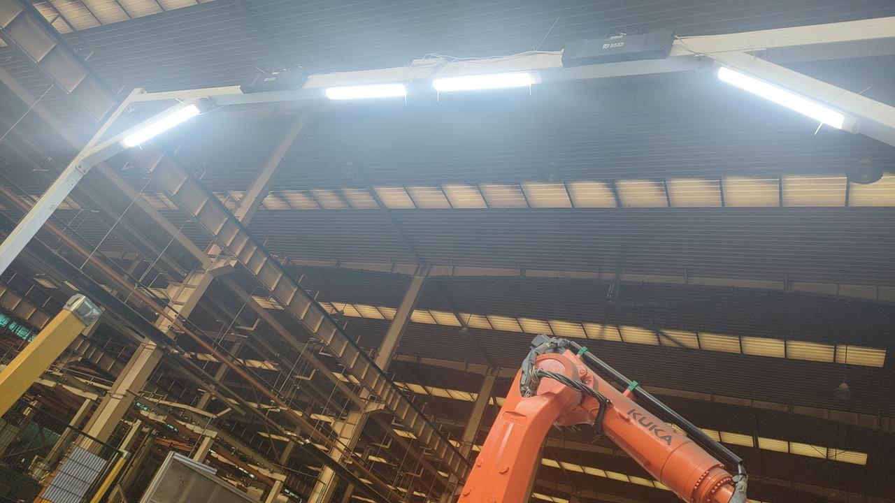
Parameter tuning approach: there is no need to consider Takt Time; use PID auto exposure and adjust it to the required brightness.
Case 4: Dezhou, Shandong - Tengyang Depalletizing
Scene characteristics: direct sunlight around three or four in the afternoon causes local overexposure on the pallet surface(the image below shows the HDR result)
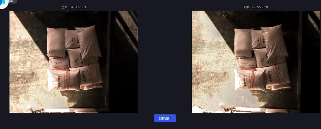
Parameter tuning approach: For scenes with large changes in ambient brightness and white sacks, Hikrobot AOI auto exposure is easily affected by the exposed bottom area, so choose PID auto exposure and set
ExposureAutoto 3. Strong local direct sunlight causes severe overexposure, so HDR high-dynamic composition is required; therefore, enable HDR with"HDREnable": 1based on the PID exposure multiplier. See the yellow-marked part in the Parameters for details."HDR": "AutoExposureTimeRates"; 0.1 is used because the sunlight is very strong and the bright areas require reduced exposure; 1 is the appropriate exposure value under normal adjustment; 1.5 is used to increase the brightness in dark areas.
Understanding binocular Cameras
Structure
A binocular Camera consists of two 2D Cameras, and the Intrinsic/Extrinsic Parameter calibration file is used to describe the relationship between the two Cameras.
Deep Learning model segmentation and recognition is based on the left image.
Essence of Parameter adjustment
In hardware terms, it is a 2D system, so Parameter adjustment is actually the adjustment of 2D Camera Parameters such as exposure and white balance. Only when exposure is adjusted properly can subsequent imaging quality and accuracy be guaranteed.
Introduction to related concepts
Baseline Length: the distance between two Cameras(plain description)
Number of binocular Point Clouds: there are as many points as pixels; that is, a resolution of 3036*4024 will produce tens of millions of Point Cloud points.
rectify: baseline correction, the process of aligning two 2D RGB images, visualized as a red-line image. You can see that the red line within the red circle passes through the same point in both images.

Disparity: in the rectified 2D images captured by the two Cameras, the horizontal pixel distance between the same point in the actual Scene in the left and right images.
Calculation formula: disp = baseline length * camera Intrinsic Parameter fx / distance from the object
scale scaling ratio: multiplying the resolution 3036*4024 by the scaling ratio 0.34 produces an image close to 1024*1280 resolution, and the Intrinsic Parameter changes accordingly during Inference.