One-Click Integration for Training Vision Models
A vision model is a Deep Learning model used to segment instances from a Scene. The vision models for sacks, cartons, circles, cylinders, and quadrilaterals are all General Models. The vision models for general Target Objects and Surface Model Target Objects are obtained by training with CAD through One-Click Connection. This article introduces how to use One-Click Connection to obtain vision models for general Target Objects and Surface Model Target Objects.
The One-Click Connection feature mainly involves two systems:
PickWiz: a desktop client running on the user's industrial PC that automatically calls DexVerse backend APIs to create new training tasks.
DexVerse: a platform that automatically triggers, manages, schedules, and monitors Deep Learning training tasks.
1. Select a task Scenario
When the Target Object is not a sack, carton, circle, cylinder, or quadrilateral, and the difference between its front and back sides is large, select the general Target Object ordered loading and unloading / Random Picking / positioning and assembly scenario;
When the Target Object is not a sack, carton, circle, cylinder, or quadrilateral, and the difference between its front and back sides is small, select the Surface Model Target Object ordered loading and unloading / Random Picking / positioning and assembly scenario.
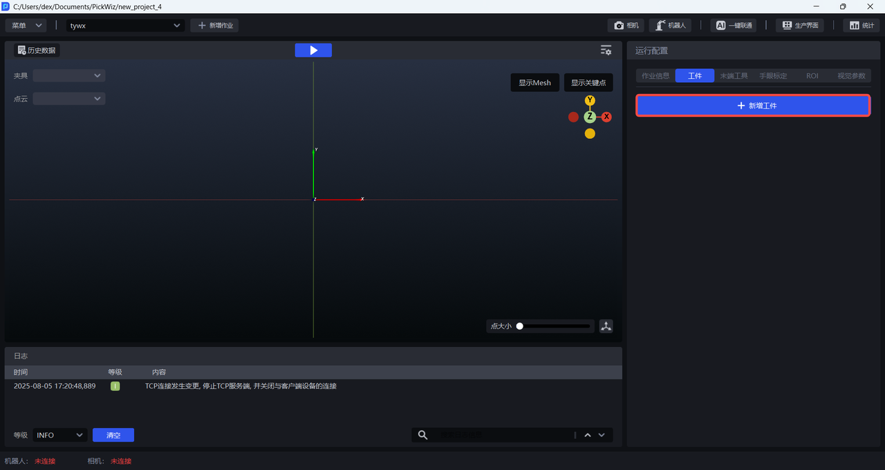
2. Configure the Target Object
Click +Add Workpiece on the Workpiece interface.
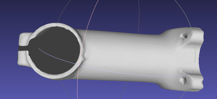
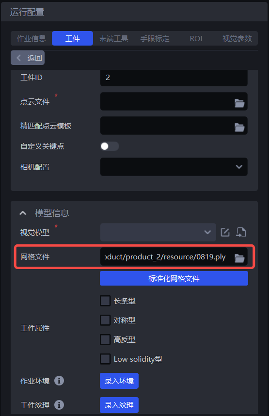
2.1 Mesh File
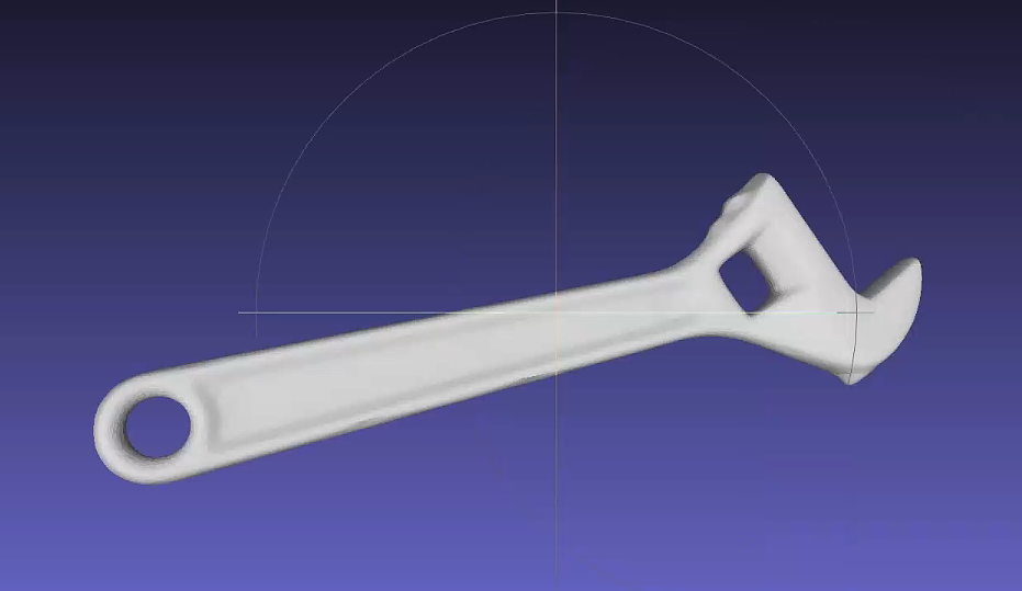
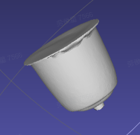
When training vision models with One-Click Connection, general Target Objects and Surface Model Target Objects rely on Mesh files to render a large number of synthetic images under different viewing angles and lighting conditions, thereby expanding the training data and improving the generalization capability of the vision model. If a Surface Model Target Object is relatively simple and has few features, you may choose not to upload a Mesh file.
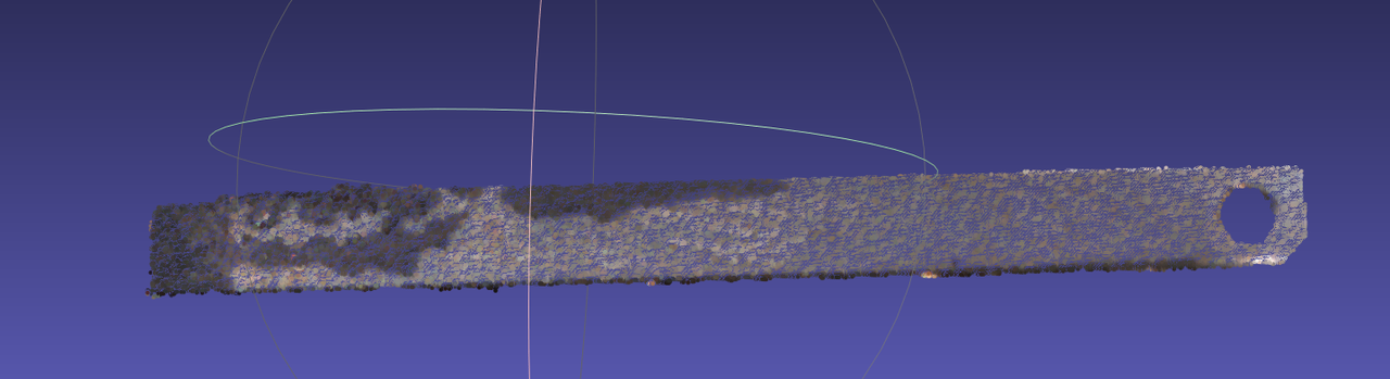
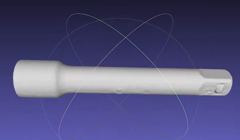
Upload the Mesh file and click Standardize Mesh File. Currently, only Mesh files in ply format are supported.
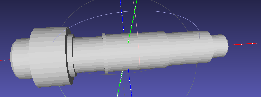
In the Point Cloud template creation module, select Mesh file processing.
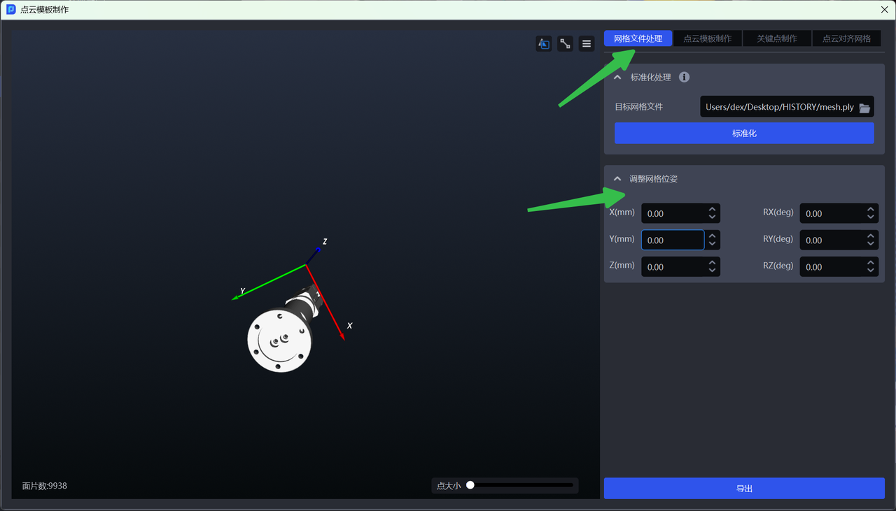
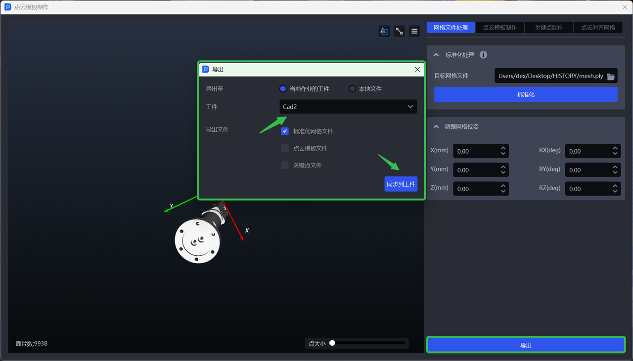
You can adjust the Mesh pose as needed and synchronize it to the Target Object of the current task during export;
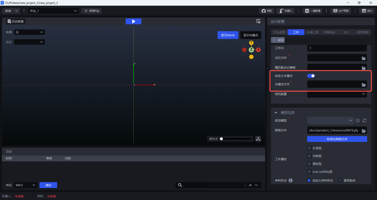
2.2 Keypoint File
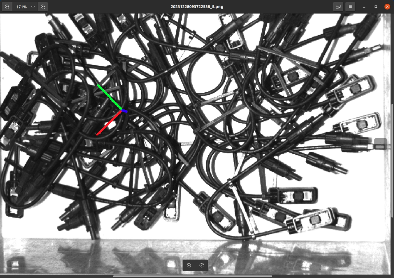
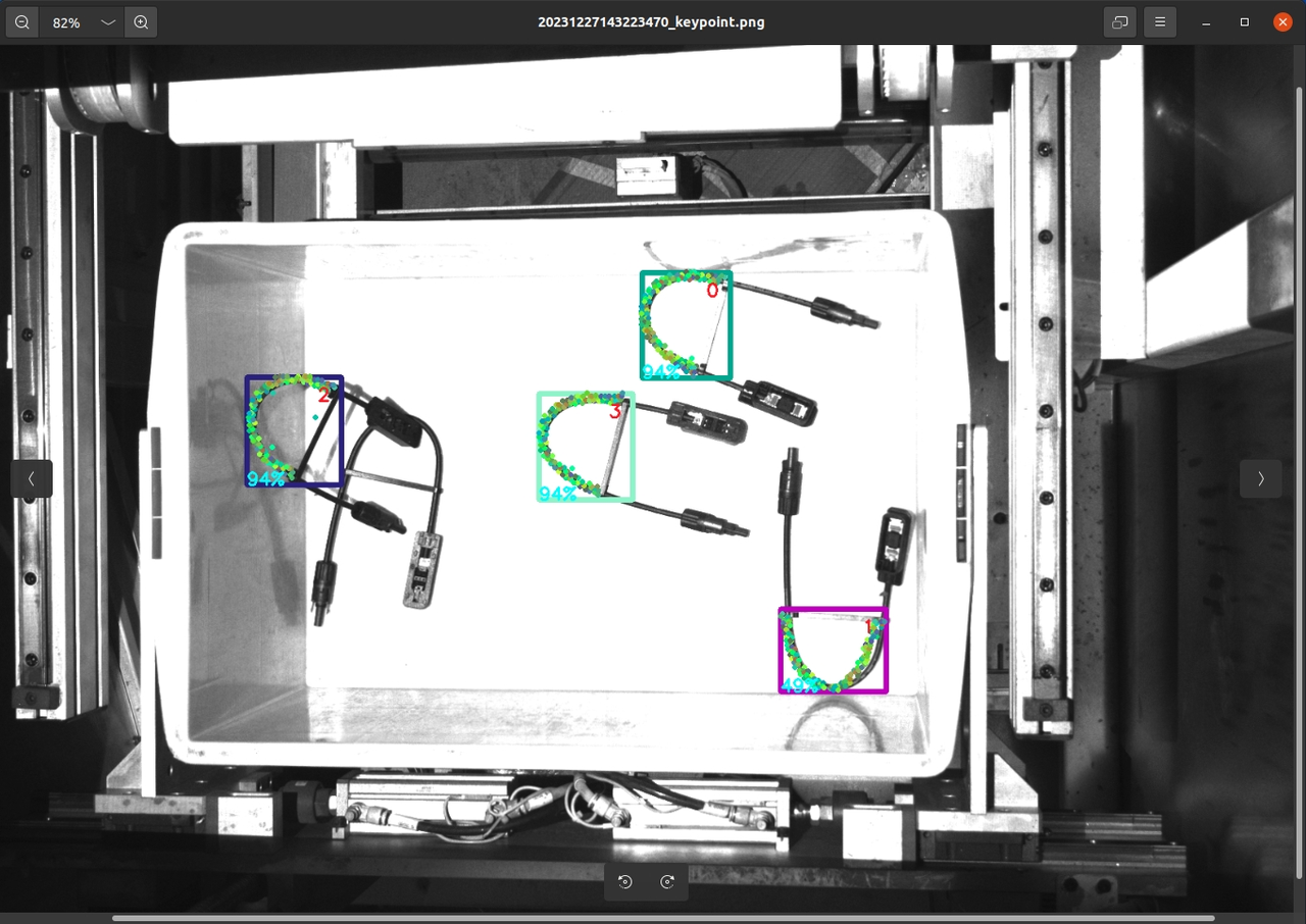
When training vision models with One-Click Connection, general Target Objects usually have obvious differences between the front and back sides, so you need to upload a keypoint file for front/back recognition. Surface Model Target Objects usually have only small differences between the front and back sides, so no keypoint file is required. Please refer to Point Cloud Template Creation Guide to create keypoints for general Target Objects.
2.3 Target Object Attributes
When training vision models for general Target Objects and Surface Model Target Objects, you can check Workpiece Attributes. One-Click Connection will generate training data that better matches the specified Target Object attributes, so the resulting vision model will have better recognition performance and robustness for Target Objects with those attributes.
If Workpiece Attributes is not checked, the generated training data will not specifically consider the designated Target Object features (such as symmetry or highly reflective materials), which may lead to less ideal recognition performance in the trained vision model.
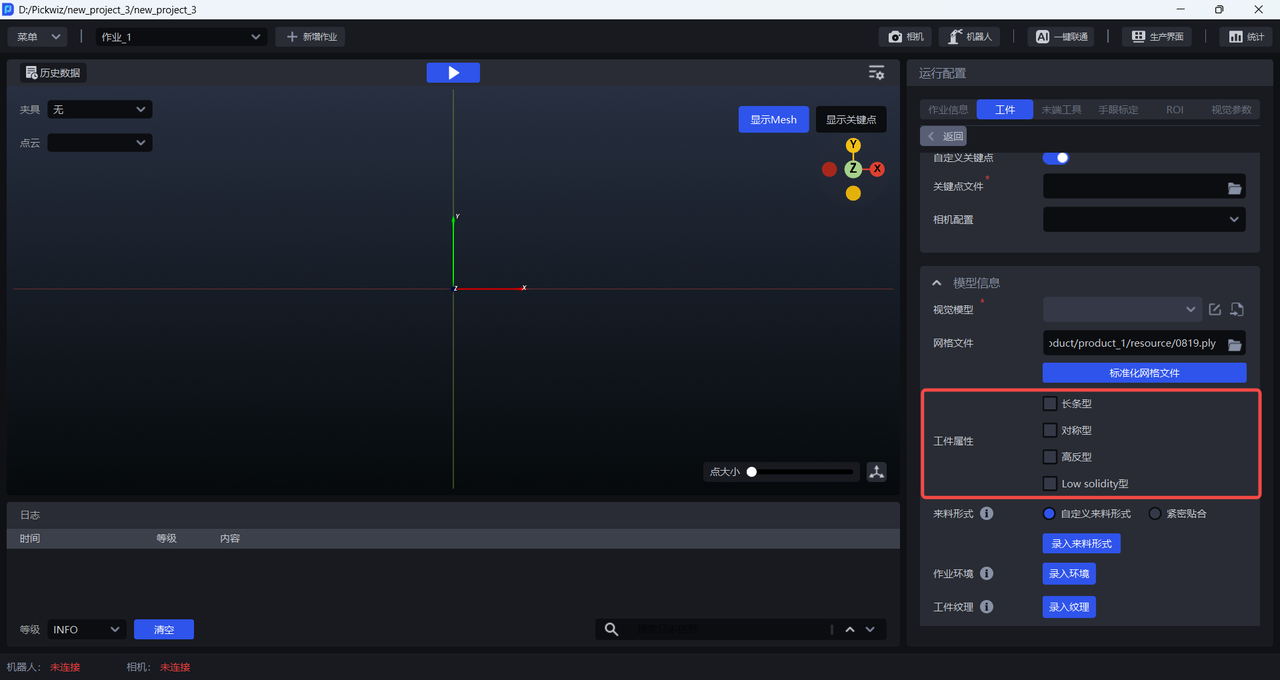
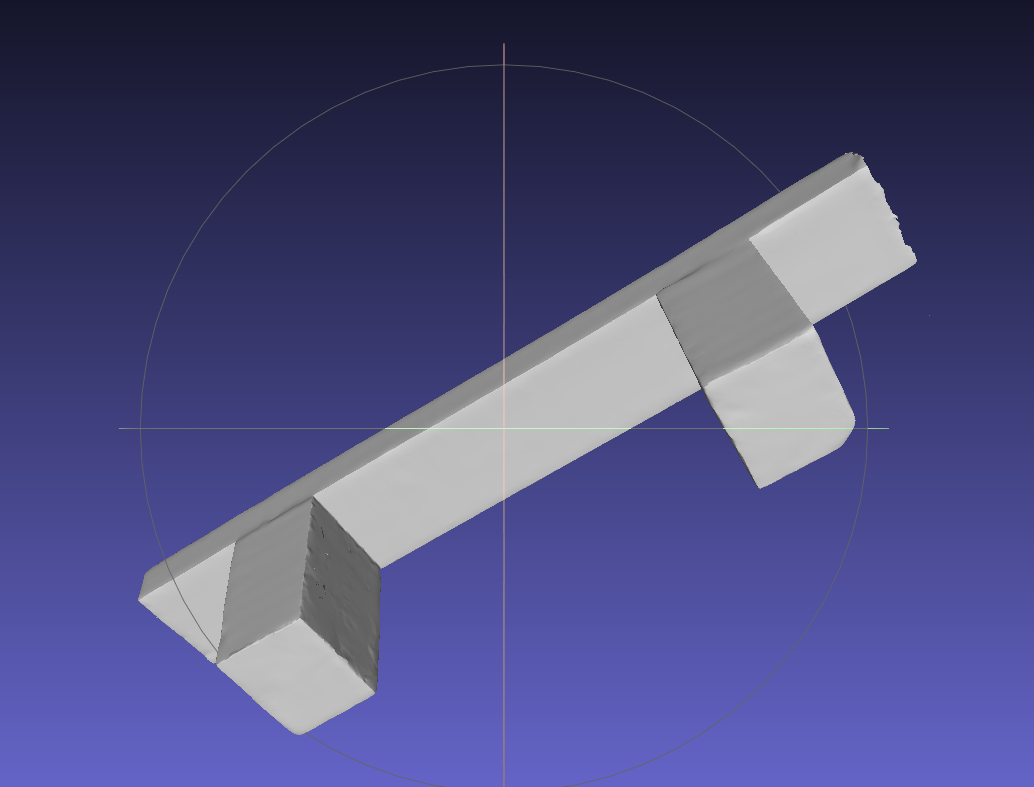
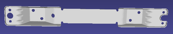
When the Target Object is a long-strip Target Object, you can check Long-strip under Workpiece Attributes;
When the Target Object is symmetrical, you can check Symmetrical under Workpiece Attributes;
When the Target Object is highly reflective, you can check Highly Reflective under Workpiece Attributes;
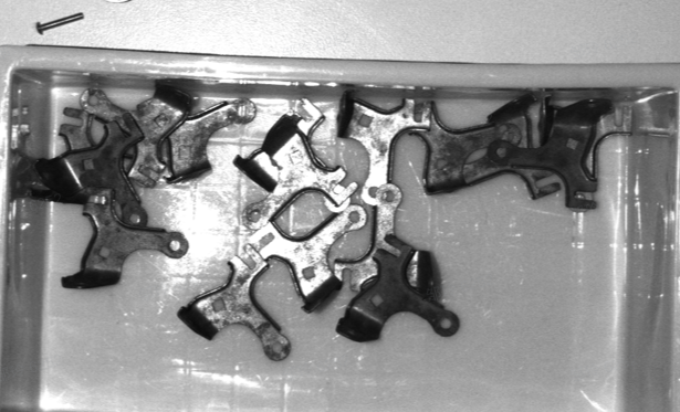

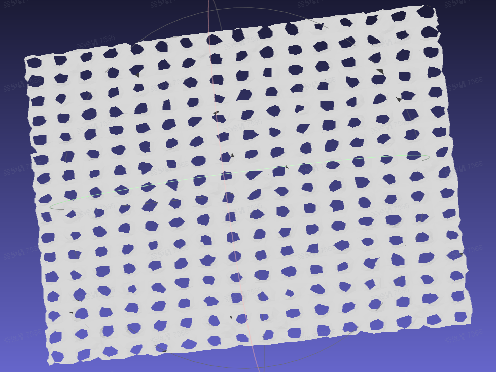
When the Target Object is low-density and hollow (such as wire harnesses), you can check Low solidity under Workpiece Attributes.
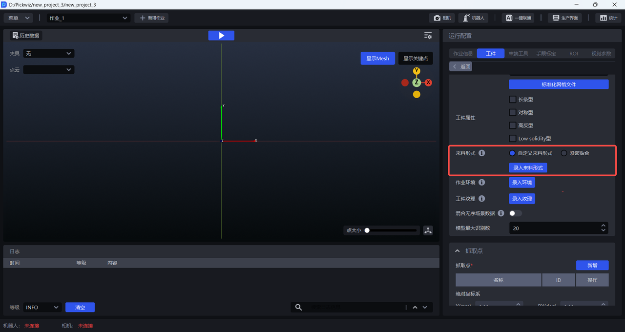
2.4 Material Arrangement
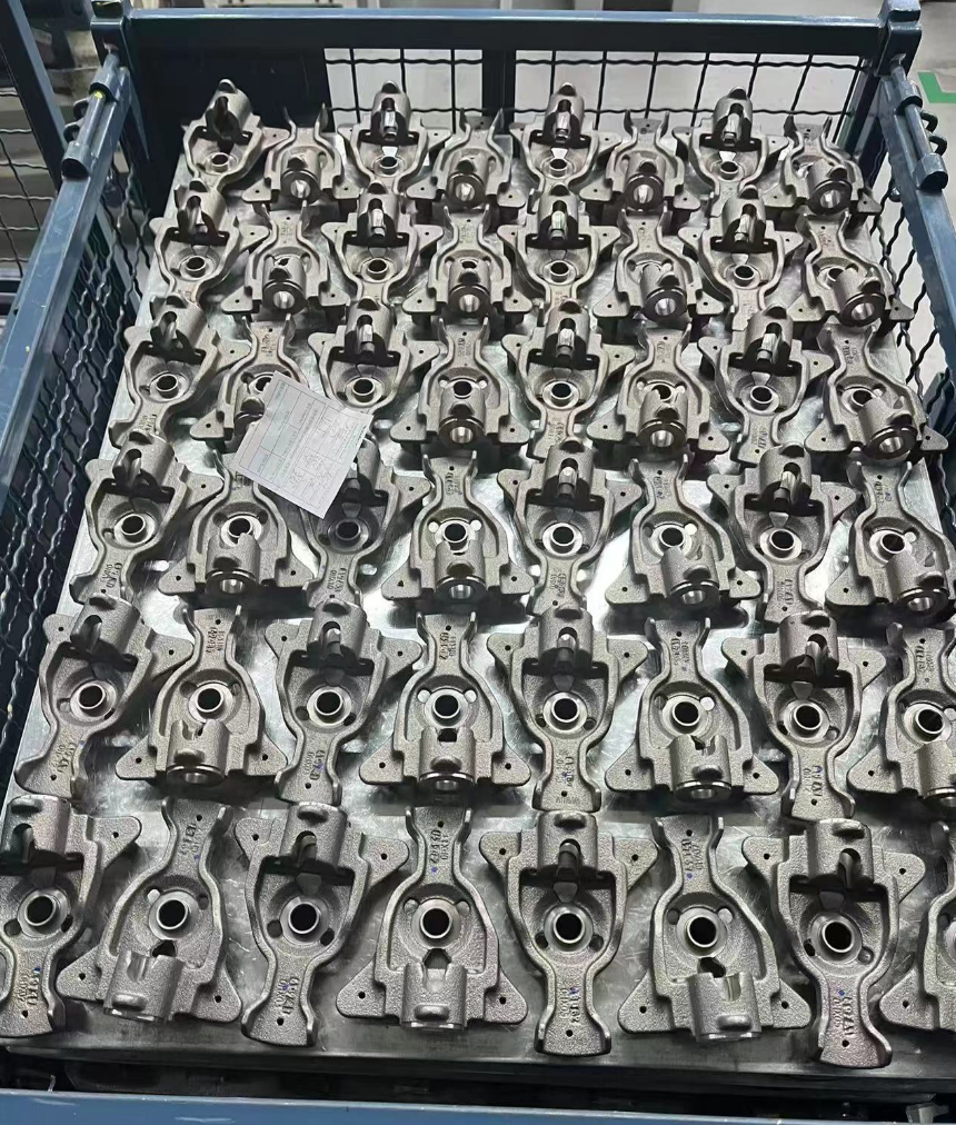
In ordered loading and unloading scenarios for general / surface-type Target Objects, you can enter the material arrangement when training vision models with One-Click Connection to simulate the incoming material pattern of the Target Objects in the actual Scene. In this way, the trained vision model will have better recognition performance and robustness in the real Scene. If the material arrangement is not entered, the recognition performance of the trained vision model may be less ideal.
There are two types of material arrangement: Close Fit and Custom Material Arrangement. Close Fit is suitable for scenarios where the Target Objects arrive in an ordered manner, with consistent poses and small spacing. Custom Material Arrangement is suitable for all scenarios with ordered incoming materials.
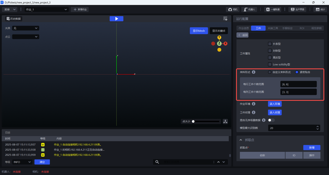
2.4.1 Close Fit
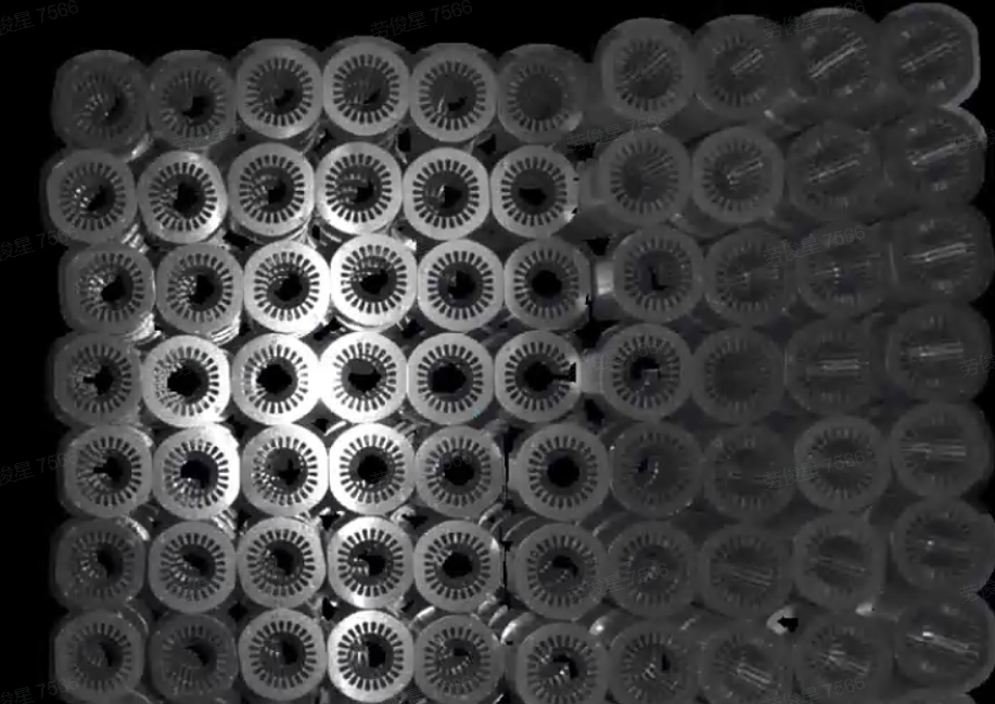
If the Target Objects arrive in an ordered manner, with consistent poses and small spacing, you can click Close Fit and set the number of Target Objects in each row and column. However, the total number of Target Objects must be less than 40. If the number of Target Objects exceeds 40, you must ensure that the ratio of the configured number of Target Objects in each row/column has the same common-divisor ratio as the actual number of Target Objects in each row/column. For example, if the actual material arrangement is 12 per row and 8 per column, then the row/column ratio is 12:8, which simplifies to 3:2. Therefore, setting 3 per row and 2 per column or 6 per row and 4 per column is acceptable, but 9 per row and 6 per column is not (it exceeds 40).
Example:
If the material arrangement of the Target Object is 6 per row and 3 per column, for a total of 18 Target Objects, then the range of the number of Target Objects per row can be set directly to [6,6], and the range of the number of Target Objects per column can be set to [3,3].
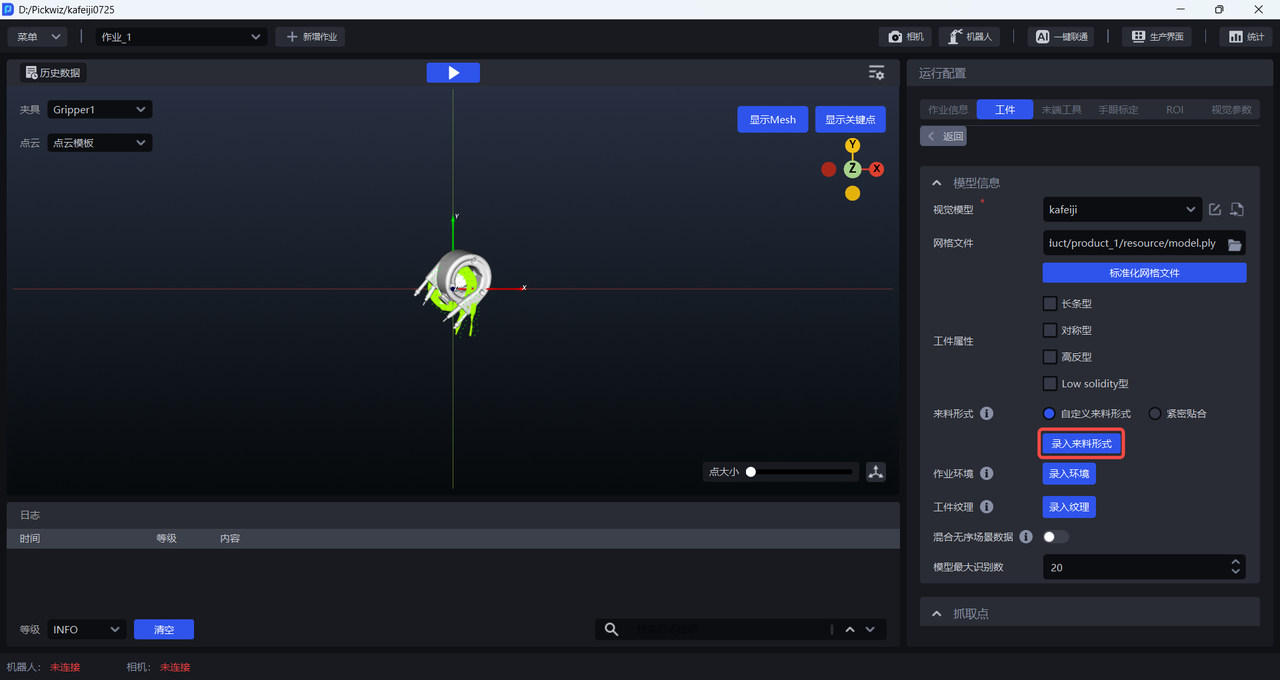
2.4.2 Custom Material Arrangement
All scenarios with ordered incoming materials can use custom material arrangements. The steps are as follows:
- Click
Enter Material Arrangementto open theMaterial Arrangement Editor
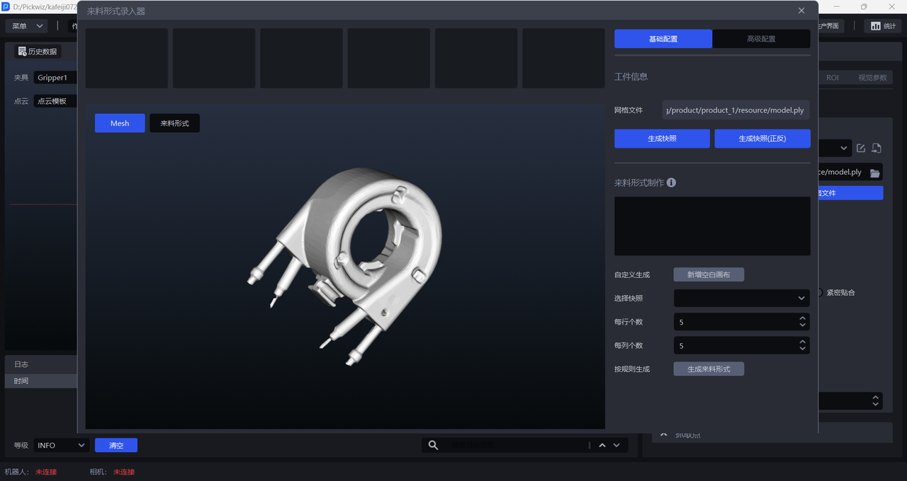
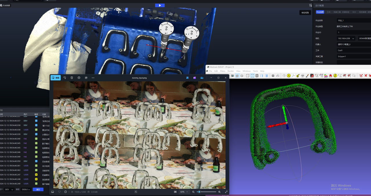
- Rotate the Mesh model to a suitable pose (the Target Object pose under the Camera view), then click
Generate Snapshot/Generate Snapshots (Front/Back)to generate snapshots of the Target Object under that pose.Generate Snapshots (Front/Back)generates snapshots from both the front and back views at the same time, as shown below.
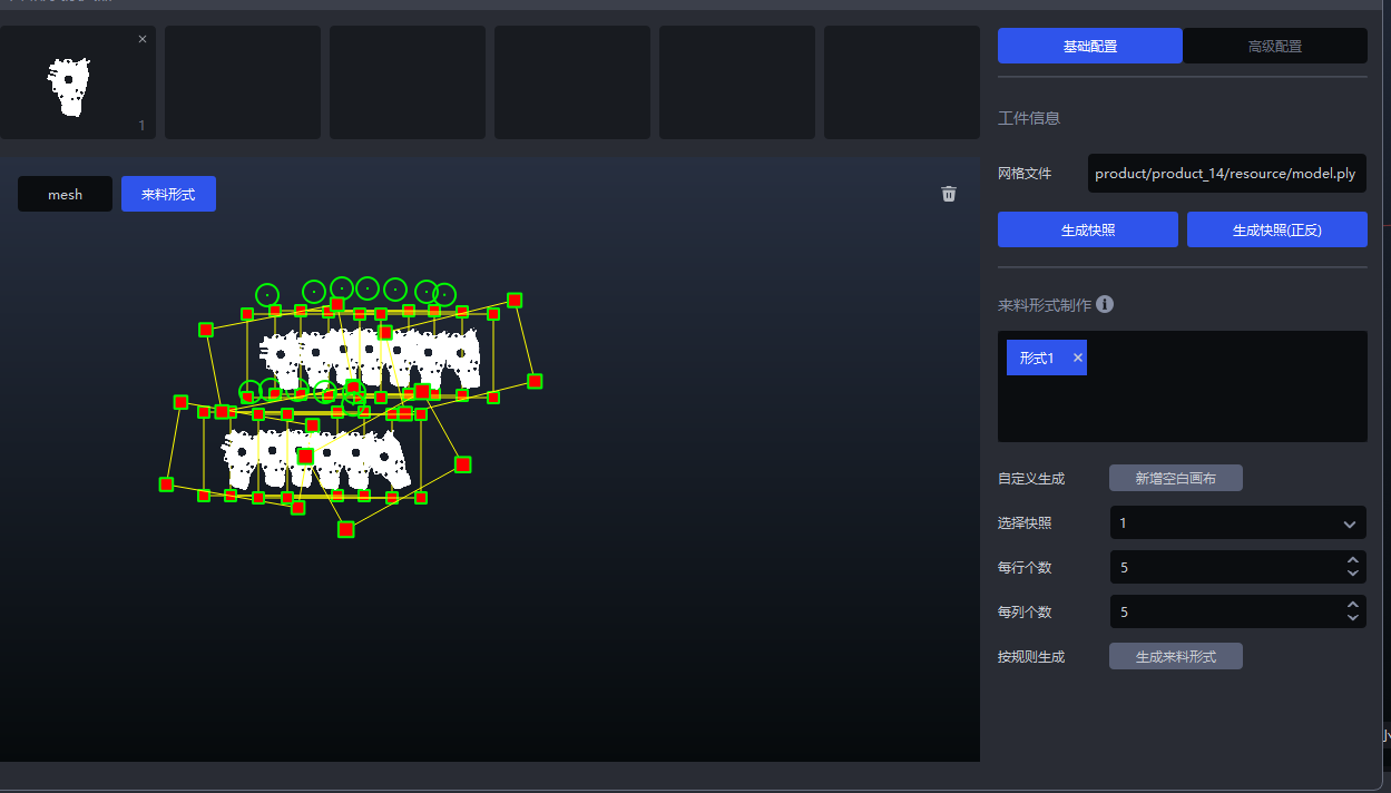
- After generating the snapshots, click
Add Blank Canvas, drag the snapshots onto the canvas, and create the material arrangement of the Target Object according to the actual Scene, as shown below.
You can also select snapshots, set the number per row and the number per column, and then click Generate Material Arrangement. The system generates the material arrangement directly on the canvas according to the selected snapshots and the configured row and column numbers, as shown below.
- After entering the material arrangement and configuring the other items one by one, once
One-Click Connectionis triggered, training for the ordered scenario will generate training data based on the entered material arrangement, as shown below.
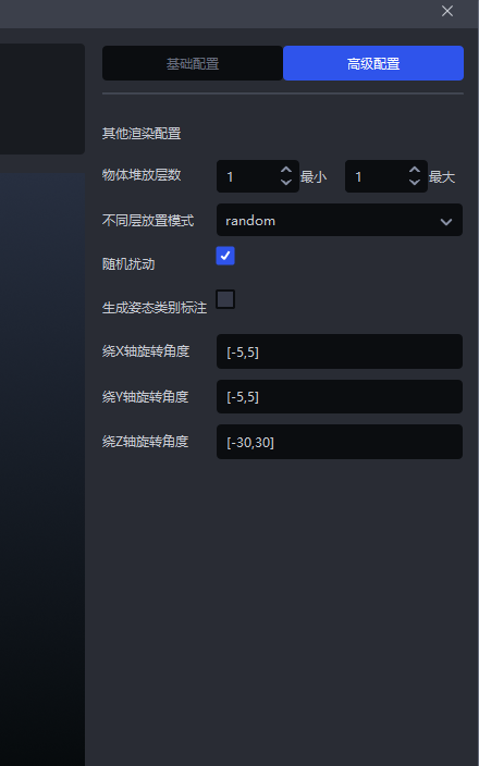
If the Target Objects are stacked in the actual Scene, click
Advanced Configurationto configure the stacking conditions, and set the rotation angle according to the Target Object pose.
Example: the Target Object pose in the Scene is rotated around the Z-axis, so set the rotation angle to [-30,30].
  |  |
|---|
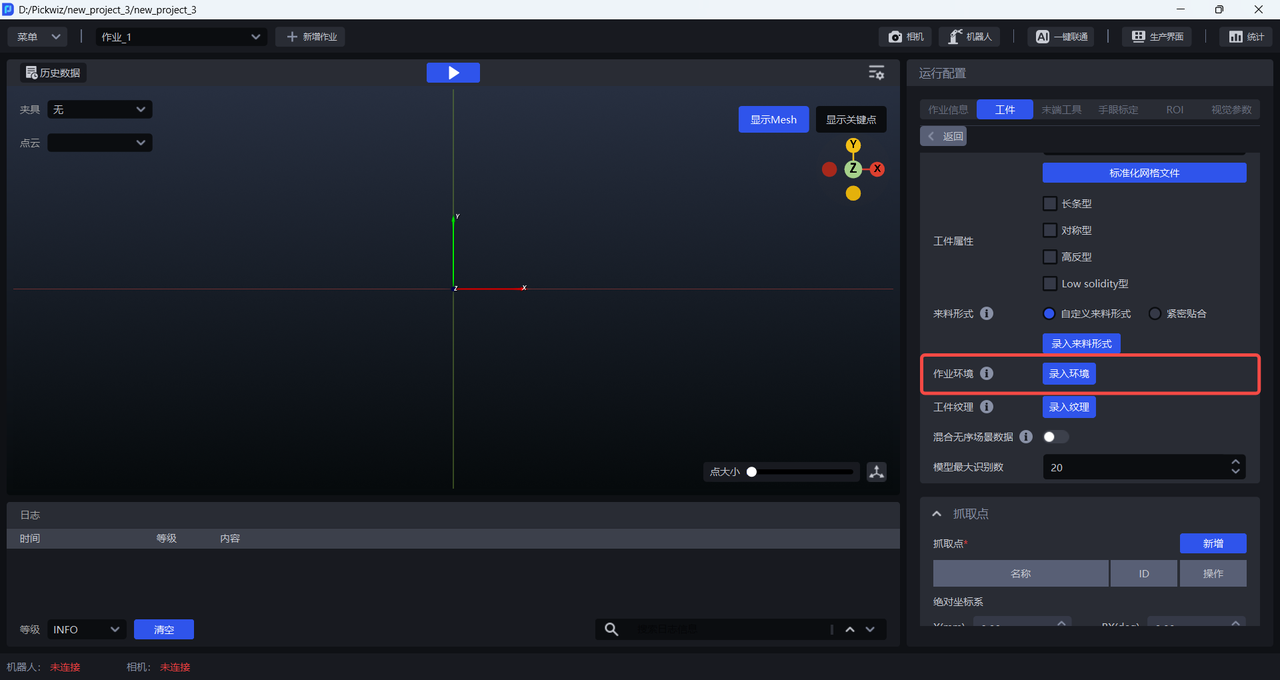
2.5 task Environment
When training vision models for general Target Objects and Surface Model Target Objects, you can enter the task environment. When One-Click Connection generates training data, it will replace the originally random backgrounds of synthetic images with the entered task-environment images, so the trained vision model will have better recognition performance and robustness in the actual Scene.
The steps are as follows:
- Click
Enter Environmentto enter theTask Environment Editor
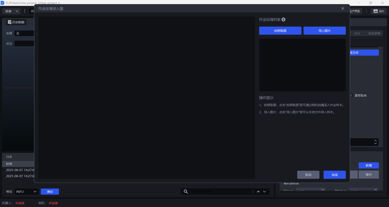
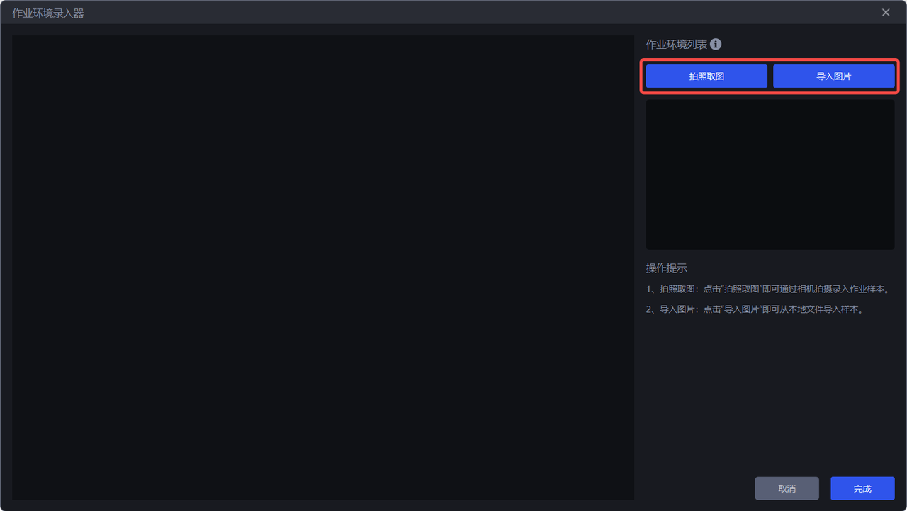
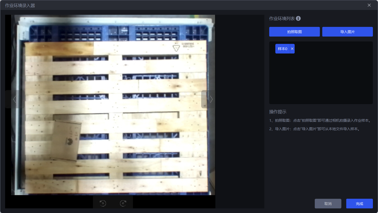
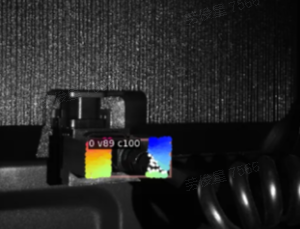
- There are two ways to obtain task-environment images: one is to use
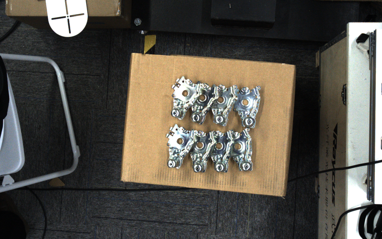
Capture Imageto capture the task environment under the Camera field of view, and the other is to directlyImport Image. task-environment images must not include Target Objects or bins, but may include pallets and base trays.
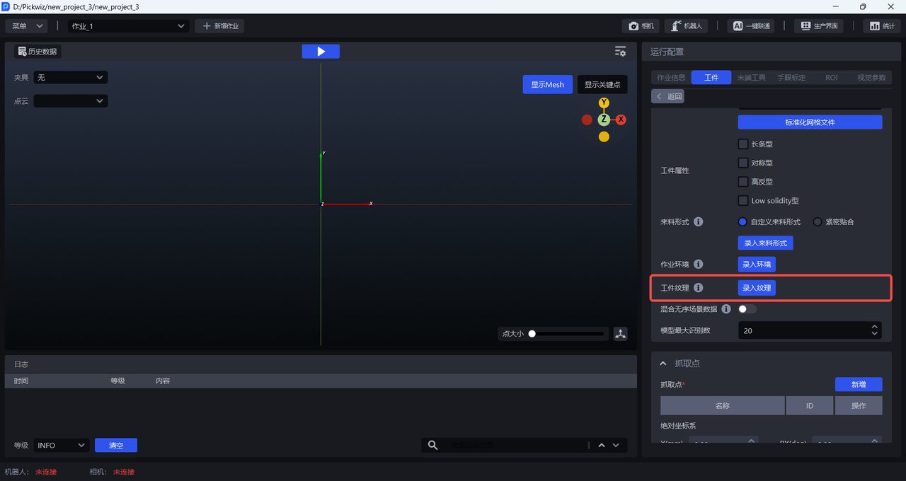
2.6 Target Object Texture
When training vision models for general / surface-type Target Objects, you can enter the Target Object texture. One-Click Connection will use the uploaded Target Object texture to generate training data, so the trained vision model will have better recognition performance and robustness for the Target Object.
The steps are as follows:
- Click
Enter Textureto enter theTexture Editor
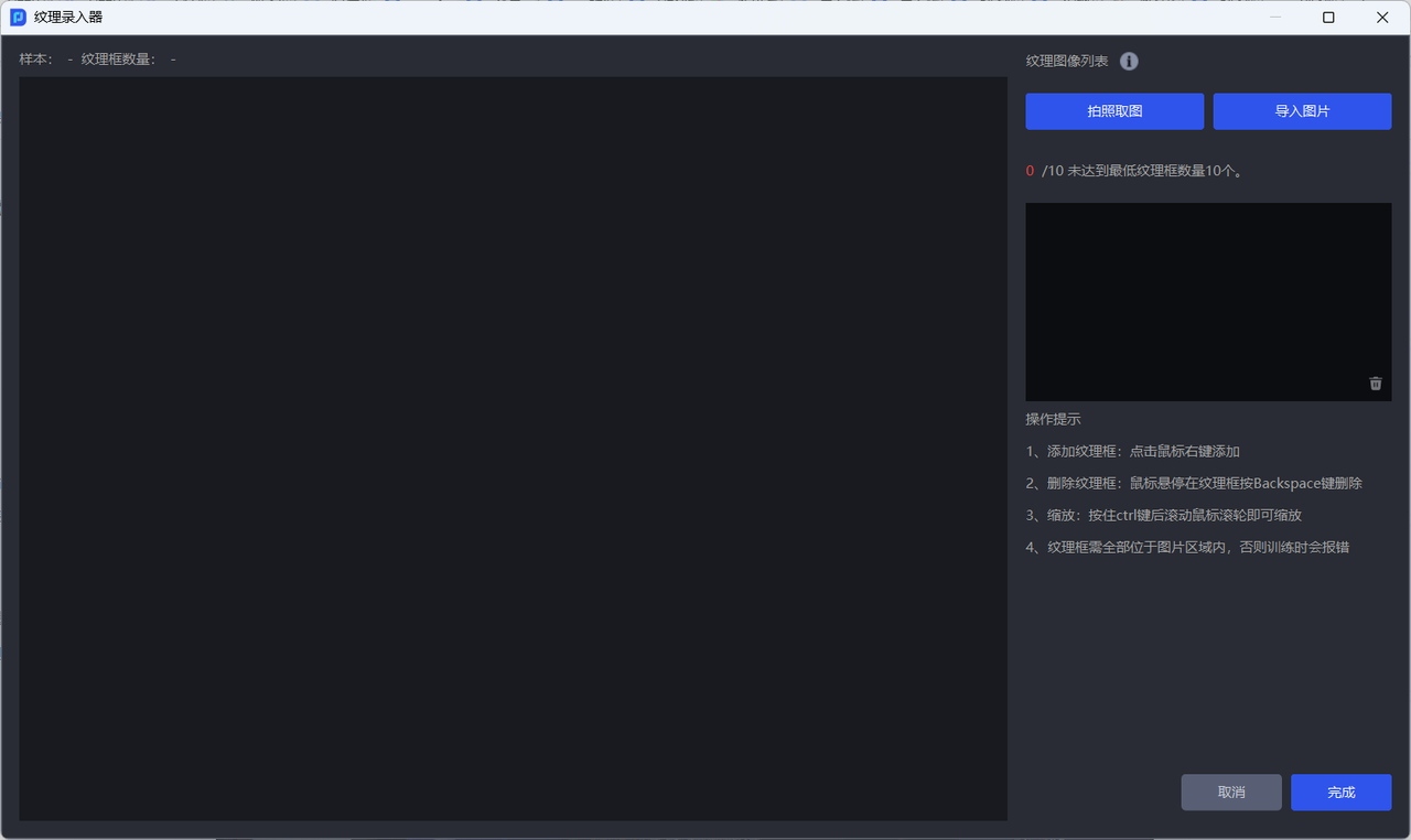
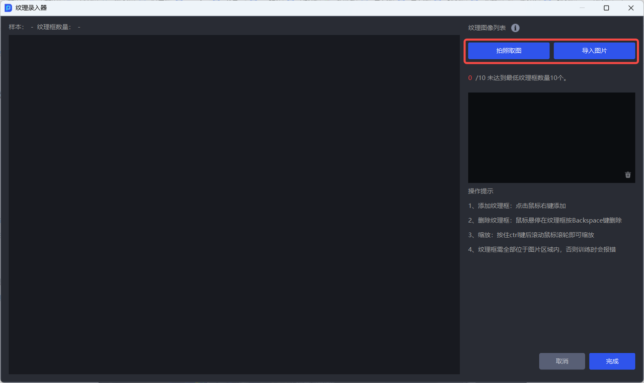
- There are two ways to obtain Target Object texture images: one is to use
Capture Imageto capture the Target Object texture under the Camera field of view, and the other is to directlyImport Image.
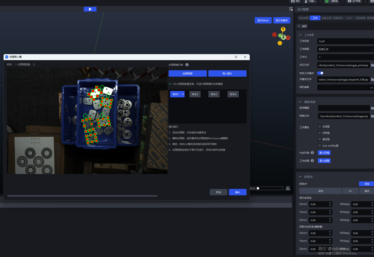
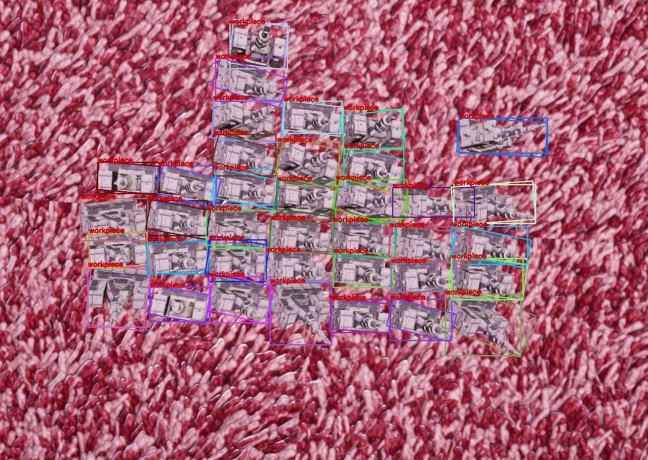
- After obtaining the Target Object texture image, right-click to add texture boxes on the image; hold down the
Ctrlkey and scroll the mouse wheel to zoom the texture box; hover the mouse over a texture box and press theBackSpacekey to delete it.
Note:
The texture box should fully frame the Target Object and fit closely to its edges, otherwise the recognition performance of the vision model will be affected;
The texture boxes must all remain within the image area, otherwise an error will occur when training the vision model.
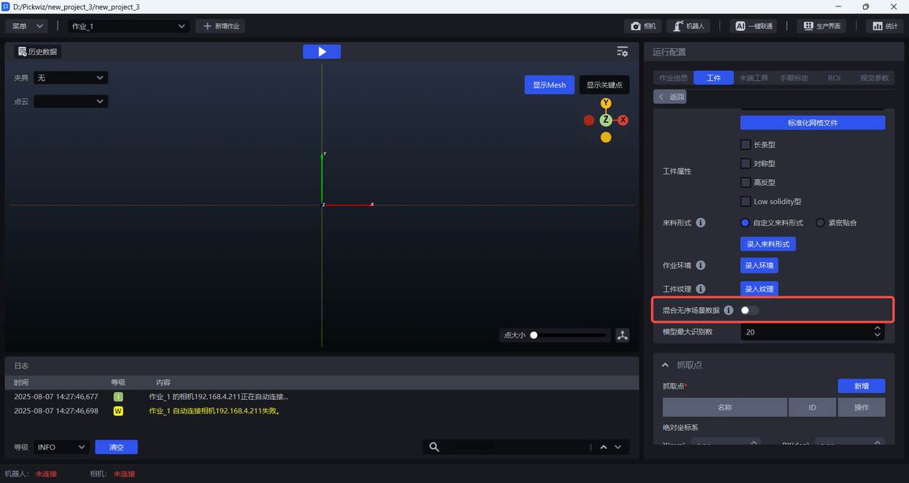
2.7 Mixed Random-Scene Data
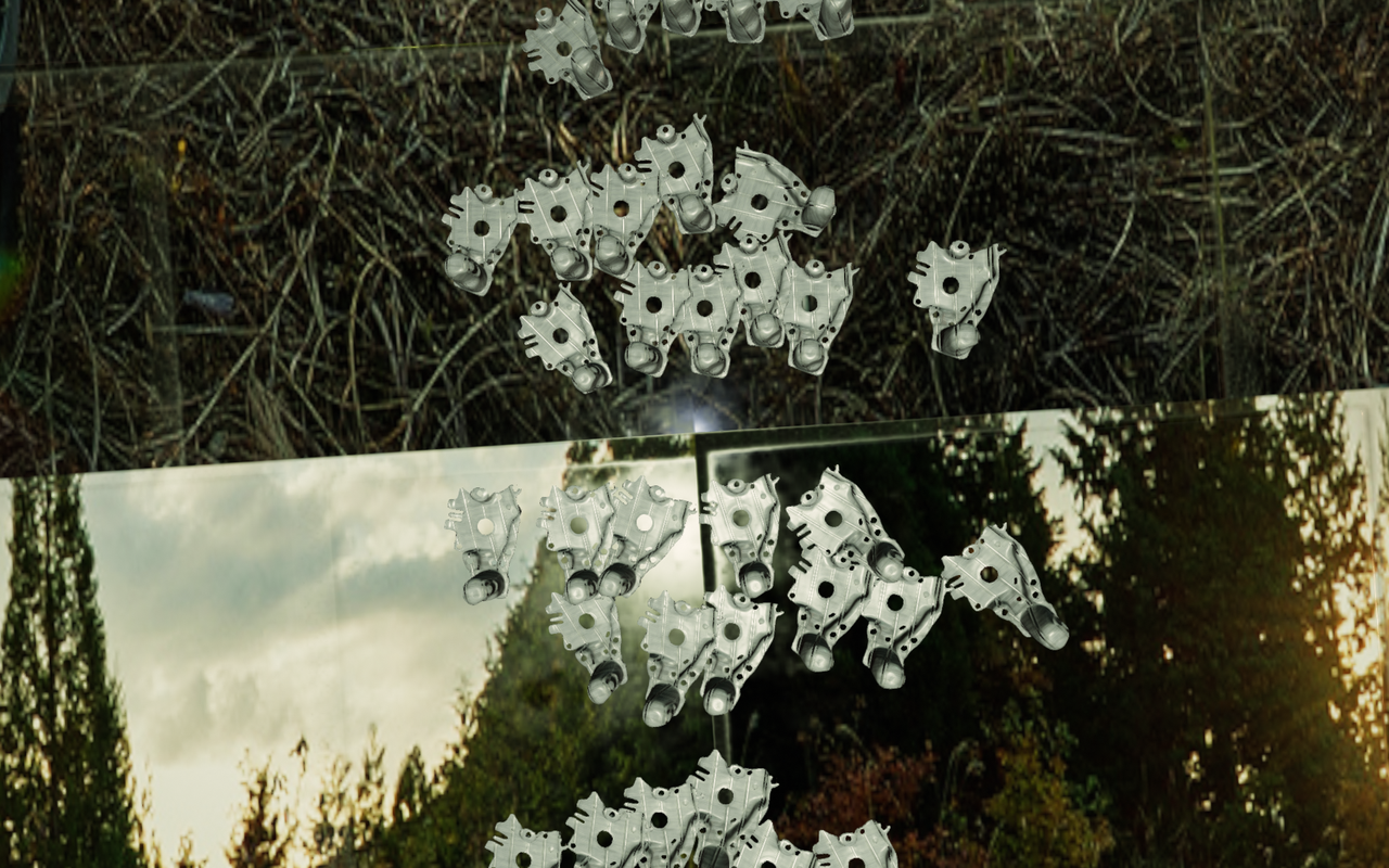
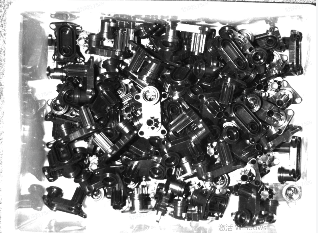
In ordered loading and unloading scenarios for general / surface-type Target Objects, if the material arrangement is ordered by rows and columns but the Target Object poses are inconsistent, you can enable Mix Random-Scene Data. One-Click Connection will generate both ordered-scene synthetic data (row/column ordered) and random-scene synthetic data (inconsistent poses) for training, so the trained vision model will have better recognition performance and robustness in scenarios with inconsistent Target Object poses.
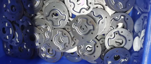
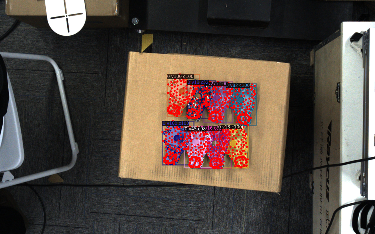
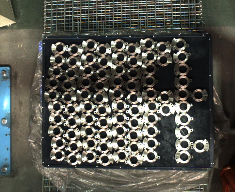
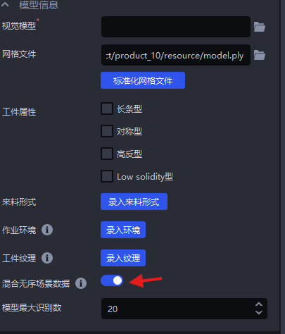
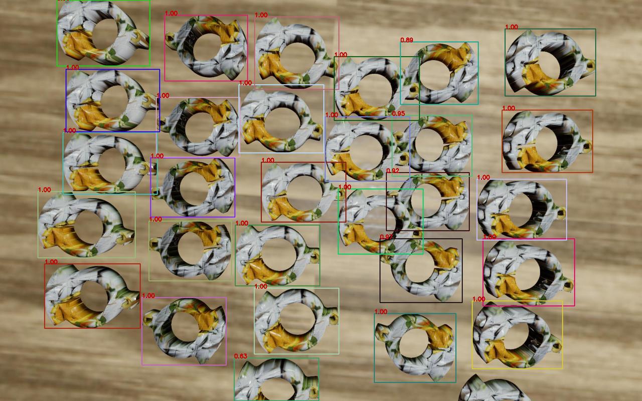
Example: for surface-type + symmetrical Target Objects, the difference between the front and back sides is already small. If Mix Random-Scene Data is enabled, the generated training data contains multiple poses, and the model may misjudge the front and back sides of the Target Object, as shown below.
Example: in a general Target Object ordered loading and unloading scenario, after enabling Mix Random-Scene Data, the synthetic images generated after triggering One-Click Connection include both the ordered row/column arrangement of the ordered scenario and the inconsistent poses of the random scenario.
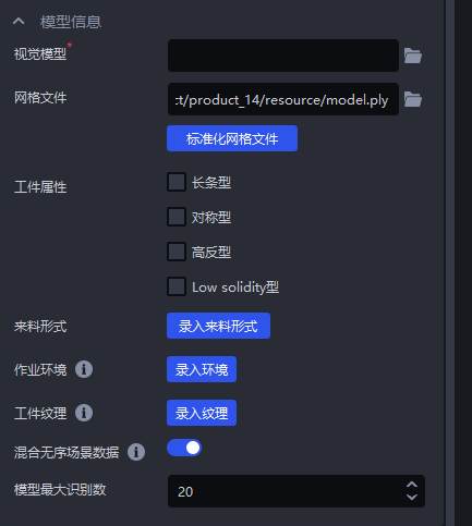
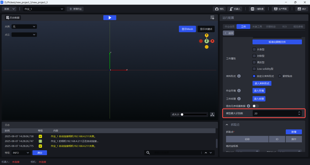
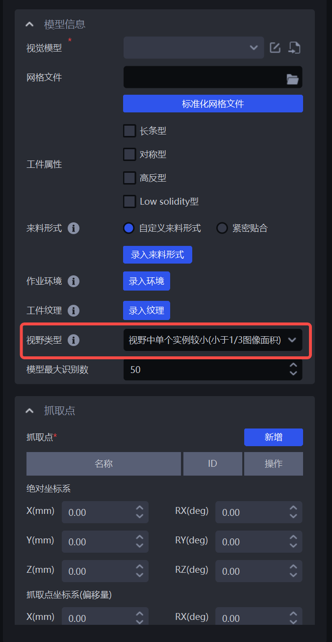
2.8 Maximum Recognition Count of the Model
The maximum recognition count of the model refers to the maximum number of instance detection results that the model can output when performing Inference on a single image. Limiting the maximum recognition count is mainly used to optimize computing resources during model Inference, reduce time consumption, and improve Takt Time. The default is 20 and can be adjusted according to the actual number of Target Objects in the Scene.
2.9 Function Options
When training vision models for general Target Objects and Surface Model Target Objects, check the corresponding function options. After One-Click Connection is triggered, the generated training data will include different Target Object types, different Target Object orientations, textures, local features, and so on, so the trained vision model will have better recognition performance for changes in actual Scenes.
2.9.1 Vision Classification
Vision Classification refers to classifying Target Objects by orientation, texture, and so on.
Example: a Target Object has two placement orientations. The same-direction Target Objects need to be picked first, and then the opposite-direction Target Objects. After enabling Vision Classification, the vision model trained by One-Click Connection can classify the Target Object orientation, thereby realizing orientation-based picking.
2.9.2 Recognition Type
Recognition Type refers to distinguishing different categories of Target Objects. The training data generated by One-Click Connection is classified according to preset categories. After inputting image data of different Target Object types, the model can learn to determine which category a Target Object belongs to.
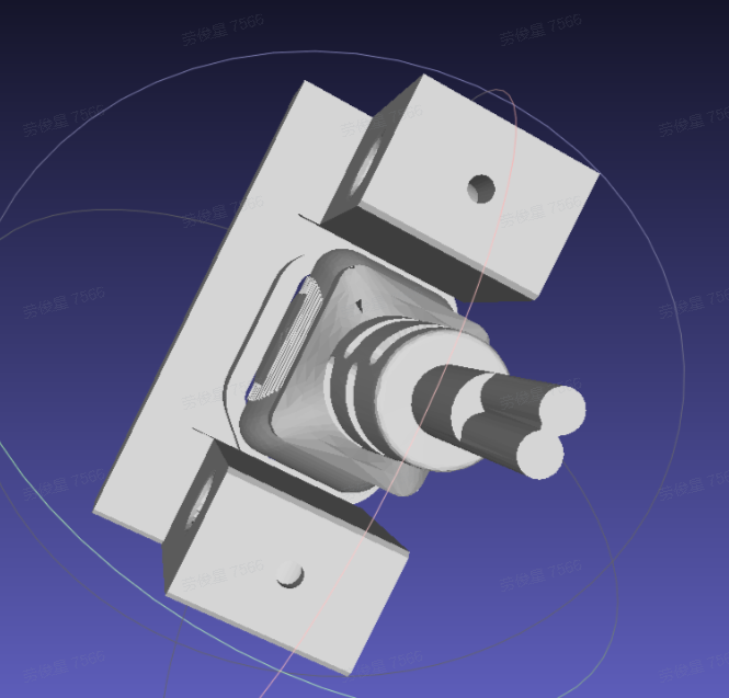
You can treat the front and back sides of a Target Object as two different types and use the Recognition Type function to generate two kinds of training data containing both sides. When using Recognition Type to train the front and back sides, you need to upload the front-side and back-side Point Clouds of the Target Object.
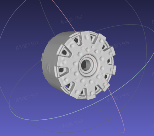
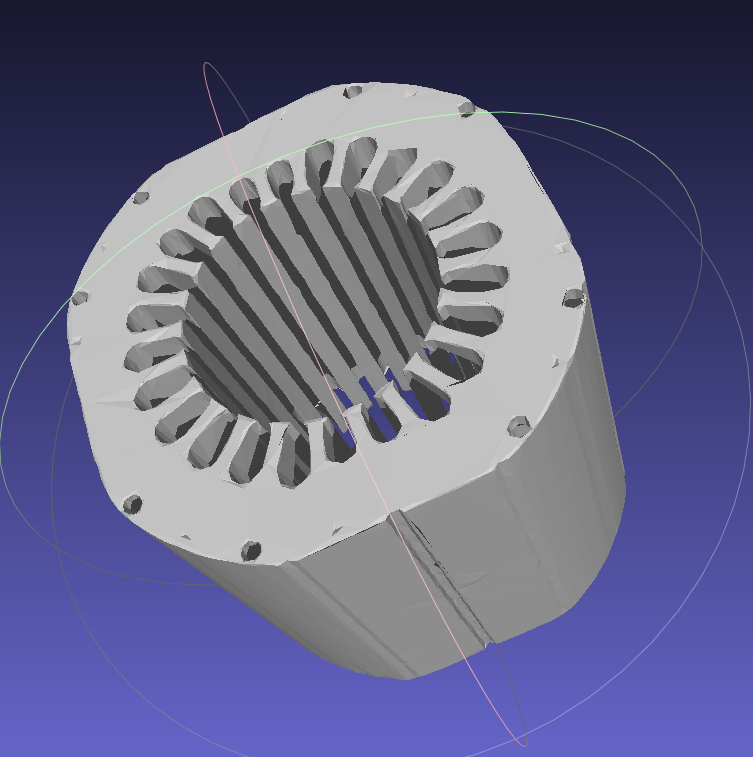
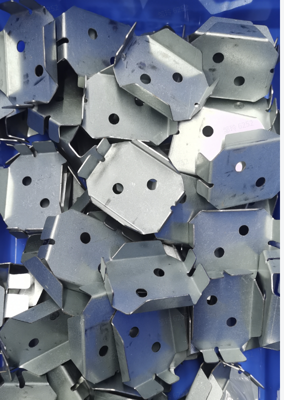
Example: the Target Object has a complex structure and its features change significantly at different angles, so when creating the Target Object Point Cloud, both the front-side and back-side Point Clouds need to be created and merged into a single Point Cloud file.
2.9.3 Recognize Local Features
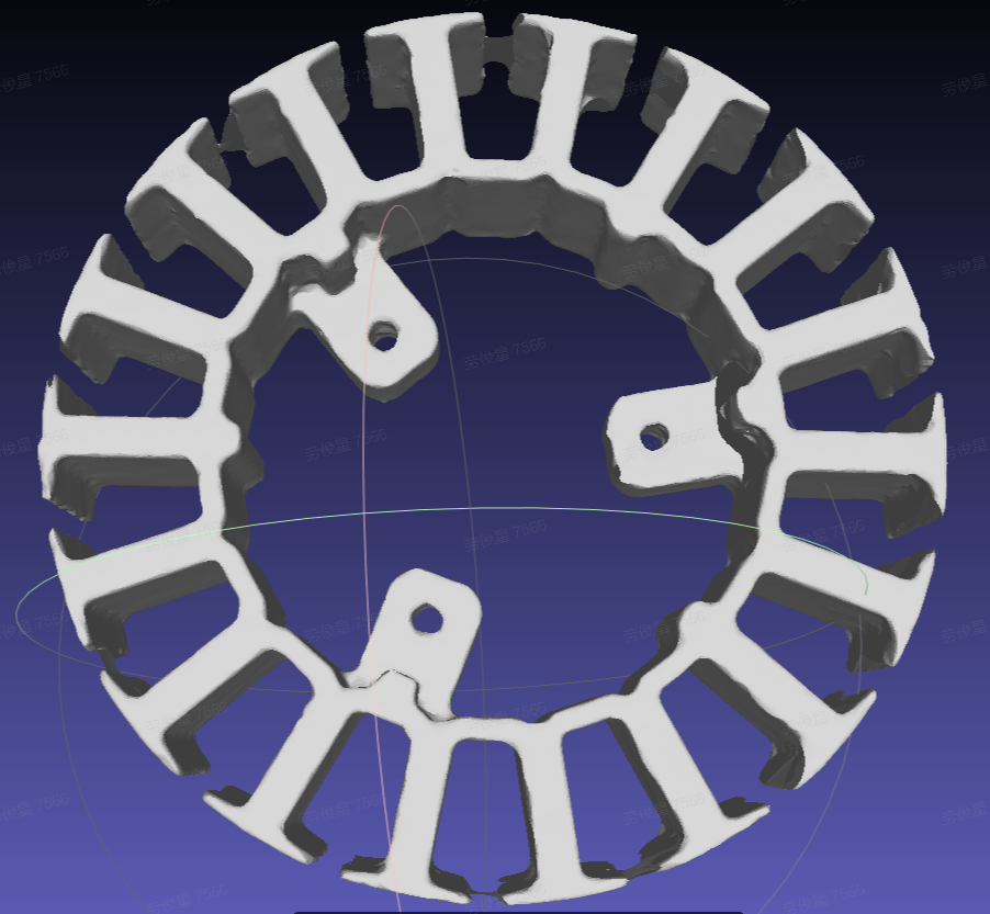
Recognize Local Features refers to identifying local features of a Target Object (such as holes, protrusions, and so on).
Surface Model Target Object Random Picking does not yet support Recognize Local Features.
Example: when there is only one Target Object in the Camera field of view, the scenario can be converted into an ordered scenario so that One-Click Connection can be used. It is necessary to use the overall CAD model to simulate the effect of occluding the recognition surface.

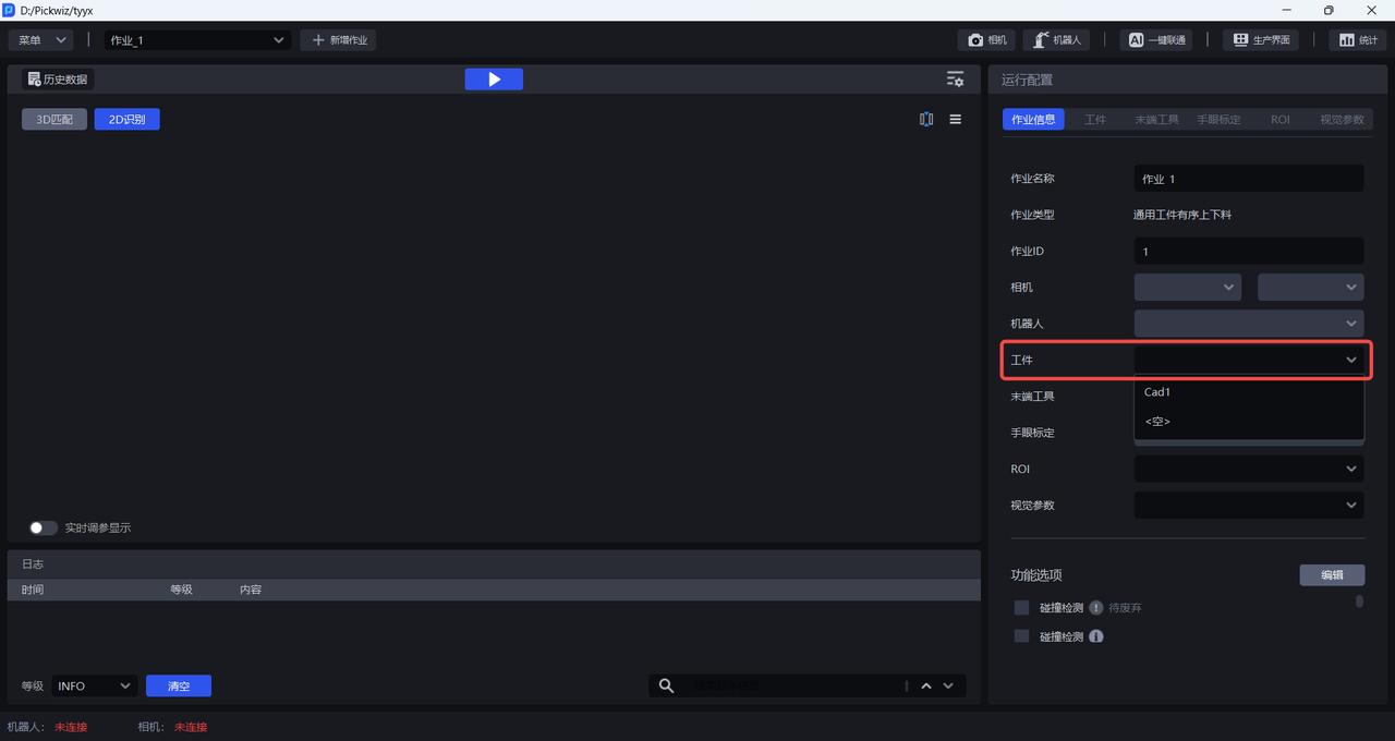
After completing the Target Object configuration, select the newly added Target Object configuration in the task information.
2.10 Field of View Type Parameter
In a single-target scenario, the field-of-view type parameter in the Target Object module can be used to specify the actual rendering height of One-Click Connection according to the actual Scene conditions.
After confirming that everything is correct, select the newly added Target Object configuration in the task information.
3. Configure ROI
Please refer to ROI Operation Guide to configure ROI 3D and ROI 2D on the ROI interface.
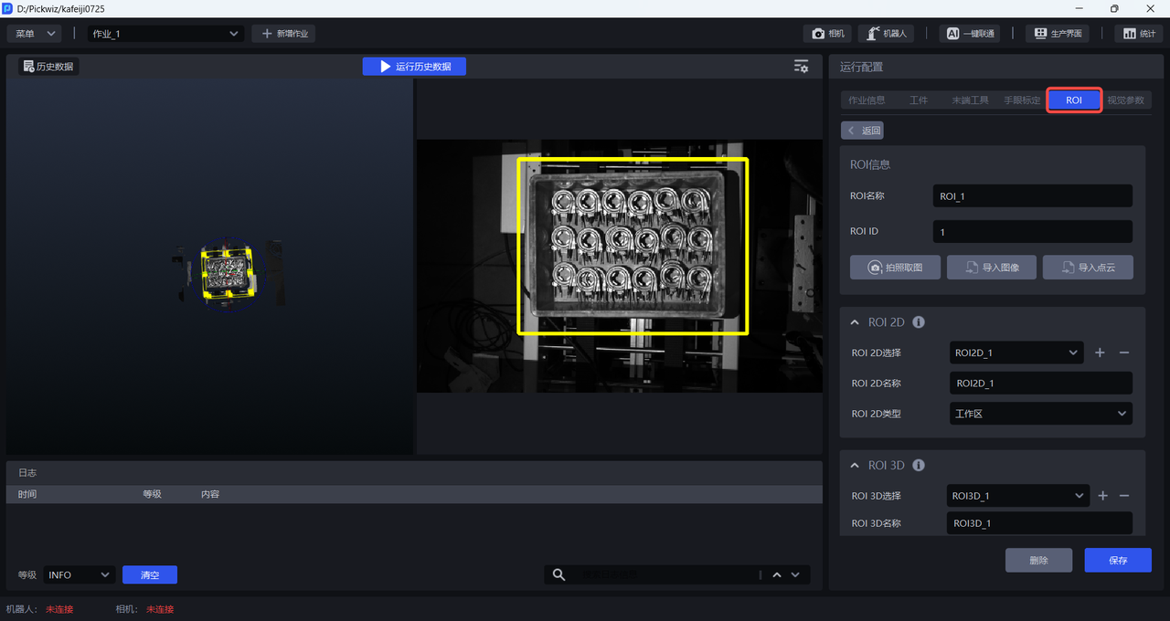
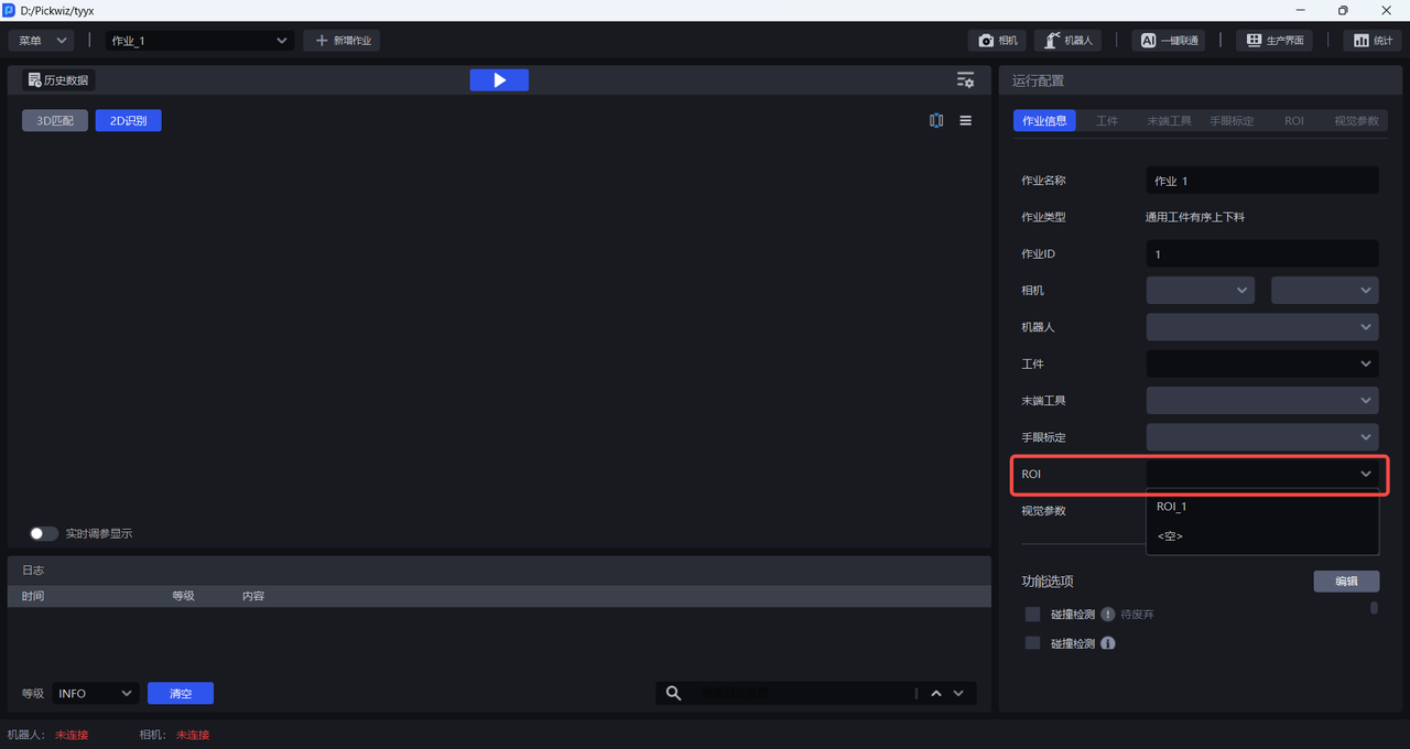
After configuring ROI 3D and ROI 2D, select the corresponding ROI in the task information.
4. Train Vision Models
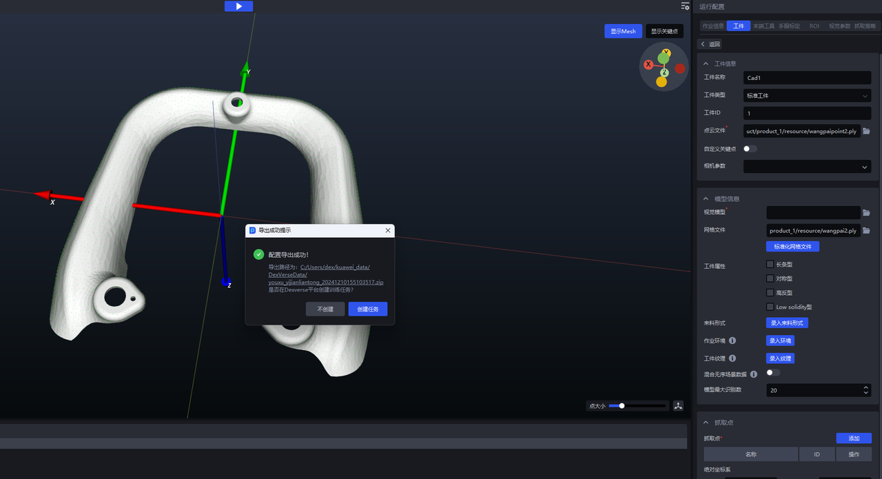
After completing the Target Object and ROI configurations, click One-Click Connection to trigger vision model training. If the input data needs to be edited manually, select Export Training Configuration Only; otherwise, select Automatically Create Training Task.
4.1 Export Training Configuration Only
Suitable for users who need to manually edit the data and later create the training task manually on the DexVerse platform.
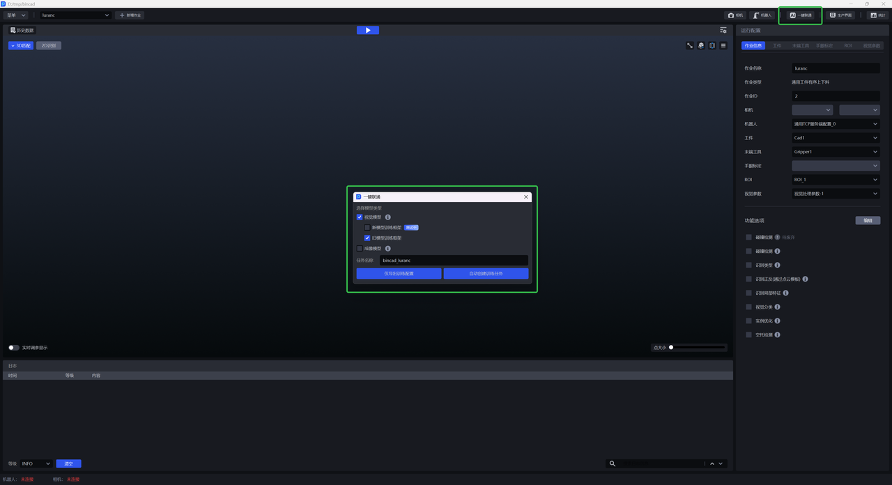
(1)On the main interface, click One-Click Connection to display the One-Click Connection pop-up window, then check Vision Model, as shown below.
(2)Click Export Training Configuration Only . You can click the link at the bottom of the pop-up window to view the contents of the compressed data package or modify the configuration.
(3)Go to the DexVerse platform to create a training task. For specific steps, see DexVerse Operation Manual.
4.2 Automatically Create a Training Task
Suitable for most scenarios. After configuring the Target Object / ROI and other items in PickWiz, a training task can be automatically created on the DexVerse platform.
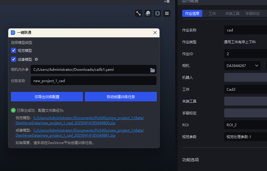
(1)On the main interface, click One-Click Connection to display the One-Click Connection pop-up window, as shown below.
(2)Check Vision Model , then name the training task so that it is easier to search for in DexVerse, and click Automatically Create Training Task .
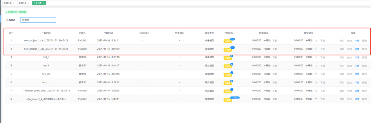
(3)Go to the DexVerse platform to view the automatically created training task. For details, please refer to DexVerse Operation Manual.
5. Train Vision Models and Imaging Models at the Same Time
In the One-Click Connection pop-up window of PickWiz, check both Vision Model and Imaging Model , then click Export Training Configuration Only / Automatically Create Training Task .