Automatic Random Pose Sampling
This calibration method is not currently supported for three-axis or four-axis Robots.
1. Preparations Before Calibration
Before eye-hand calibration, complete the following preparations:
(1)Complete the 3D Vision Guidance Kit hardware setup
Please refer to 3D Vision Guidance Kit Hardware Setup to complete the installation and connection of the Robot, Camera, and industrial PC
(2)Create a new Project and task
Please refer to Project Operation Guide and task Operation Guide to create a new Project and task
(3)Complete Camera connection and parameter adjustment and configure them in the task information
Please refer to Camera Connection and Parameter Adjustment Guide to connect the Camera, perform camera imaging quality adjustment, verify Camera accuracy, and configure it in the task information
(4)Complete Robot communication configuration
Please refer to Robot Configuration and Communication Operation Guide to establish communication between the Robot and PickWiz. For automatic calibration, you must configure two communication fields separately
Robot vision inspection send command: add the following
Capture calculation type (${co}), set to 3 to indicate an automatic calibration request
Robot pose (${p}), representing the Robot sampling pose
Automatic calibration sampling send command: add the following
Calibration sampling result (${sr}): indicates the sampling result
Next sampling pose (${cp}): the next Robot position for collecting a Calibration sample
(5)Prepare the materials required for calibration
- For the Calibration Board to be used, ensure that it is flat and clear, with no obvious scratches, dirt, bending, or deformation;
2. Calibration Information Configuration
2.1 Eye to hand
Go to the eye-hand calibration interface, click Add Eye-Hand Calibration, and enter the calibration information configuration interface
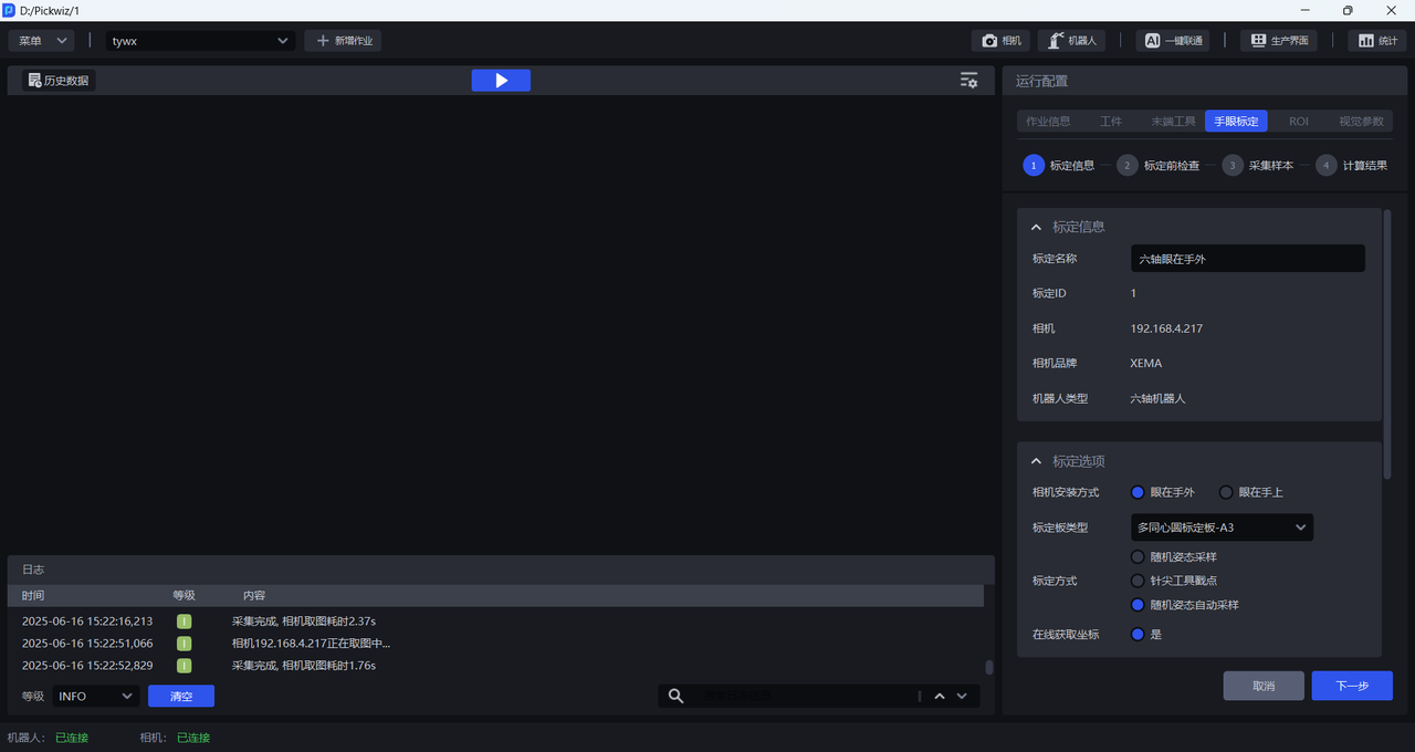
Calibration Namelets you name the current calibration configurationCalibration IDis used by the Robot to switch calibration configurationsCamerais the IP address of the currently connected CameraCamera Brandis the brand of the currently connected CameraRobot Typemust be consistent with the Robot type in Robot ConfigurationFor
Camera Installation Method, selectEye-to-HandFor
Calibration Board Type, select the current Calibration Board type
The appropriate Calibration Board mainly depends on the Robot type and the Camera mounting height. Refer to the table below and select the proper Calibration Board according to the actual application scenario.
| Robot Type | Camera Mounting Height | Select Calibration Board |
|---|---|---|
| Six-axis Robot | Below 0.5 m | A6 multi-concentric-circle Calibration Board |
| Below 1.5 m | A5 multi-concentric-circle Calibration Board | |
| 1.5 m -- 2.5 m | A4 multi-concentric-circle Calibration Board | |
| Above 2.5 m | A3 multi-concentric-circle Calibration Board |
For
Get Coordinates Online, selectYesAutomatic calibration sampling distribution
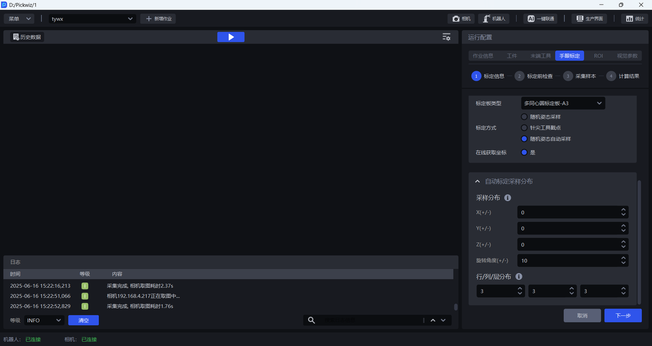
Sampling Distribution: This configuration uses the current position as the origin (based on the Robot coordinate system). You can set the Robot movable sampling range along the positive and negative X/Y/Z axes, as well as the rotation angles for sampling while fixed at the Initial Pose. Ensure that the sampling range remains within the Camera field of view, with no collision risk and sufficient clearance. Units are (mm) and (°).
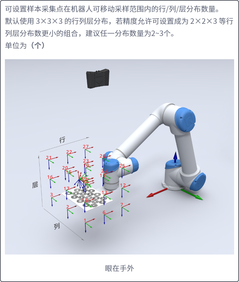
Row/Column/Layer Distribution:
You can set the number of sample collection points in the row/column/layer distribution within the Robot movable sampling range.
By default, a 3x3x3 row/column/layer distribution is used. If accuracy requirements allow, you can use a smaller combination such as 2x2x3. It is recommended that each distribution count be 2~3. Unit: (count)
2.2 Eye in hand
Go to the eye-hand calibration interface, click Add Eye-Hand Calibration, and enter the calibration information configuration interface
Calibration Namelets you name the current calibration configurationCalibration IDis used by the Robot to switch calibration configurationsCamerais the IP address of the currently connected CameraCamera Brandis the brand of the currently connected CameraRobot Typemust be consistent with the Robot type in Robot ConfigurationFor
Camera Installation Method, selectEye-in-HandFor
Calibration Board Type, select the current Calibration Board type
The appropriate Calibration Board mainly depends on the Robot type and the Camera mounting height. Refer to the table below and select the proper Calibration Board according to the actual application scenario.
| Robot Type | Camera Mounting Height | Select Calibration Board |
|---|---|---|
| Six-axis Robot | Below 0.5 m | A6 multi-concentric-circle Calibration Board |
| Below 1.5 m | A5 multi-concentric-circle Calibration Board | |
| 1.5 m -- 2.5 m | A4 multi-concentric-circle Calibration Board | |
| Above 2.5 m | A3 multi-concentric-circle Calibration Board | |
| Three-axis/Four-axis Robot | Below 0.5 m | A6 multi-concentric-circle Calibration Board |
| Below 1.5 m | A5 multi-concentric-circle Calibration Board | |
| 1.5 m -- 2.5 m | A4 multi-concentric-circle Calibration Board | |
| Above 2.5 m | A3 multi-concentric-circle Calibration Board |
For
Calibration Method, selectRandom Pose Sampling CalibrationFor
Get Coordinates Online, selectYesAutomatic calibration sampling distribution
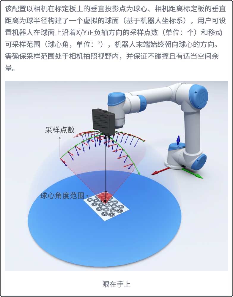
Sampling Distribution: This configuration constructs a virtual sphere (based on the Robot coordinate system) using the vertical projection point of the Camera onto the Calibration Board as the sphere center and the vertical distance from the Camera to the Calibration Board as the sphere radius. You can set the number of sampling points and the movable sampling range (central angle) along the positive and negative X/Y axes on the sphere surface. The Robot end always faces the sphere center. Ensure that the sampling range remains within the Camera field of view, with no collision risk and sufficient clearance. Units are (count) and (°).
Sampling Distribution:
Vertical distance from the Camera to the Calibration Board (mm): default value is 1500.
Number of sampling points on the sphere great circle (count): default value is 5.
Sampling central angle range (°): default value is 20.
3. Pre-calibration Checks
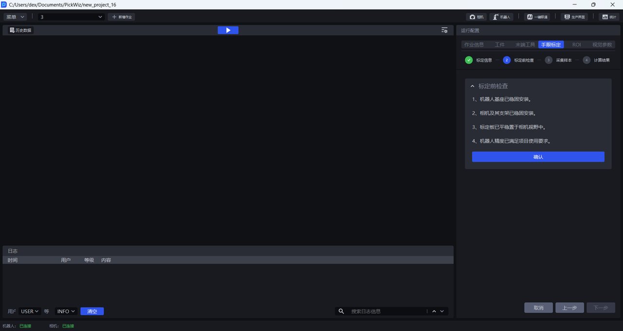
- Ensure that the Robot base is securely installed
Before eye-hand calibration, carefully check the installation of the Robot base. If the Robot base is not securely installed, the Robot may shake noticeably during movement, affecting Robot accuracy and therefore the calibration result.
Check whether the Robot base installation meets the requirements as follows:
First, the surface on which the Robot base is installed must be flat and clean;
Second, operate the Robot at 100% speed with large translational or rotational movements and observe whether there are signs of shaking. If shaking occurs, readjust and secure the Robot base to ensure that no displacement or tilting occurs during Robot movement;
Third, check whether the Robot body and base are tightly connected, and tighten the screws to prevent loosening.
- Ensure that the Camera and its bracket are securely installed
Before eye-hand calibration, carefully check the installation of the Camera and its bracket. If the Camera or bracket is not securely installed, camera imaging quality may be affected, which in turn affects the calibration result.
Check whether the Camera and its bracket installation meets the requirements as follows:
First, check whether the Camera bracket is a machined part, and avoid using aluminum profiles as the bracket material;
Second, shake the bracket and observe whether there is any obvious wobble. If so, readjust and secure the bracket;
Third, shake the Camera and observe whether there is any obvious wobble to ensure that the Camera is securely installed.
- Ensure that the Calibration Board is stably placed within the Camera field of view
If the Camera mounting method is Eye to hand, install the Calibration Board on the end tool and ensure that the Calibration Board is within the Camera field of view.
If the Camera mounting method is Eye in hand, place the Calibration Board on the work platform and ensure that it is within the Camera field of view.
- Ensure that Robot accuracy meets the Project requirements
If Robot accuracy does not meet the Project requirements, refer to Calibration Verification to correct Robot accuracy.
4. Collect Samples
4.1 Collect multiple sets of Calibration Board and Robot coordinates
This Procedure completes a closed-loop calibration workflow triggered by the Robot. On the Robot side, pay particular attention to Initial Pose calibration and real-time status feedback to ensure uniform spatial distribution of sampling data and system robustness.
4.1.1 Parameter definitions for Robot configuration
Robot vision inspection send command
p: current Robot pose coordinates
co: capture calculation type (fixed value 3 indicates automatic calibration sampling)
PickWiz automatic calibration sampling send command
sr: sampling result status code (determines the process flow)
cp: coordinate command for the next sampling point (the default value indicates termination)
4.1.2 Operating Procedure
Initialization configuration
Go to the Robot configuration interface and complete the one-time setup:
Vision Inspection Send CommandandAutomatic Calibration Sampling Send CommandEnable the current Robot configuration solution
Startup preparation
Select the calibration configuration and go to the sampling page
Move the Robot to the Initial Pose
Initial Pose calibration: Ensure that the Calibration Board is in the central area of the Camera field of view so that the samples are distributed evenly
Automatic sampling stage
Trigger the first inspection through the Robot communication program:
Different brands require different standard communication programs. Confirm before deployment whether a program is provided.
The Robot sends a vision inspection command containing
p=Initial Poseandco=3PickWiz automatically generates the sampling distribution, records the first sample, and returns the
srstatus code and the newcpcoordinates
Repeat the following operations:
The Robot moves to the new pose according to the returned
srstatus code andcpcoordinatesThe Robot sends PickWiz a vision inspection command containing
p=Current Poseandco=3PickWiz performs sampling and returns the
srstatus code and the newcpcoordinates to the RobotSampling ends automatically when the Robot determines that
cpis the default value (empty value)
Different calibration sampling results correspond to different signal values, as follows:
0: automatic sampling completed successfully
1: new sample added successfully
11: failed to add a new sample. At this time, you can pause and check the failed items in the
Inspection Results12: automatic sampling ended after reaching the minimum number of samples. Because some attempts to add new samples failed during the process, the number of successful additions was insufficient. Check whether the Robot Initial Pose is within the field of view, or reset the automatic sampling distribution parameters
13: failed to generate the sampling pose. Confirm that the Robot configuration and sample distribution configuration are correct
14: calibration startup exception: the automatic calibration sampling page was not opened
15: system error: contact technical support
4.1.3 Vision Result Analysis
The inspection includes 4 aspects:
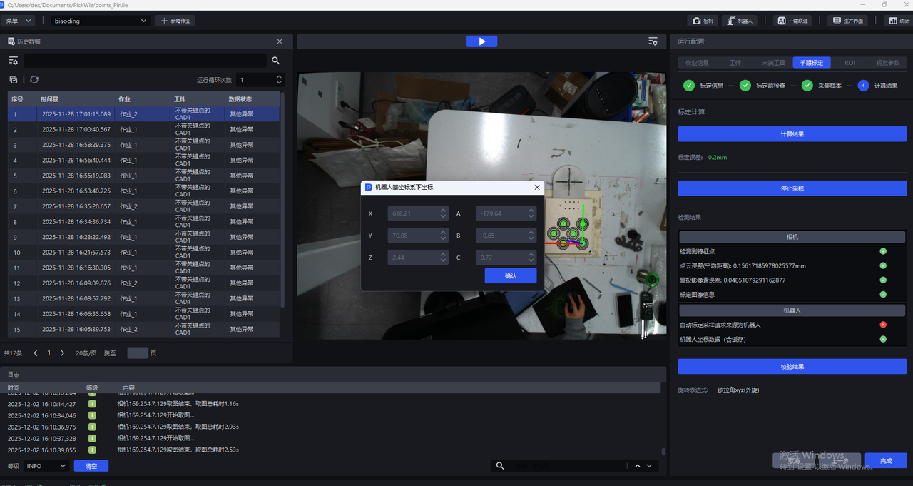
Calibration Image Information: eye-hand calibration image
Robot inspection:
4.2 Calculate the Calibration Result
Click 计算结果. PickWiz calculates the calibration result based on the collected samples. If the calibration error does not meet the requirements, perform Calibration Result Inspection and Analysis.
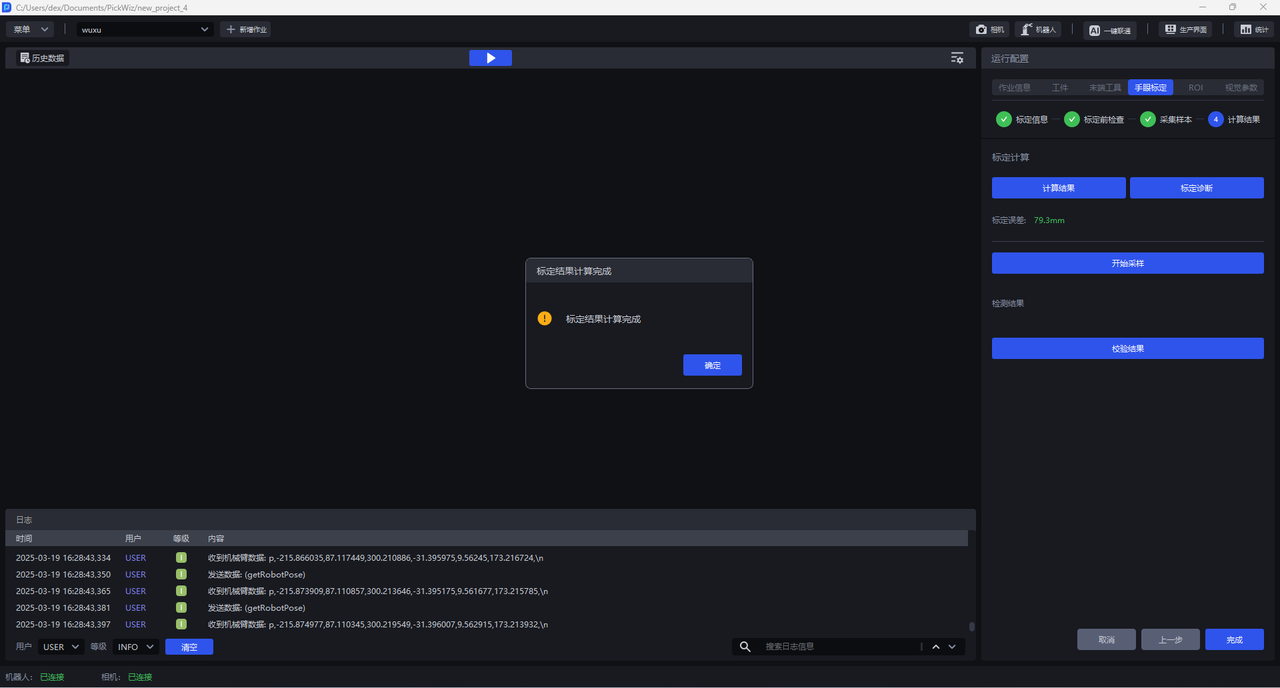
5. Calibration Result Inspection and Analysis
If the Calibration Error exceeds the normal range, identify the cause of the error. Click Calibration Diagnosis and refer to Calibration Result Inspection and Analysis to analyze the calibration result, resolve the issue, and check again until the calibration accuracy meets the application requirements.
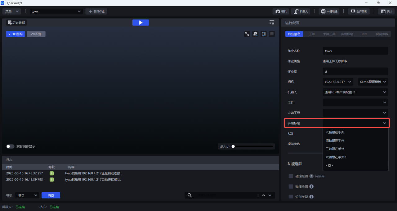
6. Select the eye-hand calibration configuration
After the calibration Procedure is complete, return to the Run Configuration interface, click Task Information, click the Eye-Hand Calibration drop-down list, and select the corresponding eye-hand calibration configuration.