Real-time Vision Thermal Drift Correction Guide
1. Create a new calibration sphere task
Create a new calibration sphere task for the [Positioning Assembly] Scene and configure the task.
Run the calibration sphere task to obtain the detected Picking Pose as the reference pose for vision thermal drift correction. Record it because it will be used in the following steps.
2. Configure vision drift correction parameters
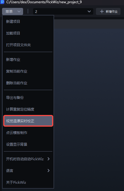
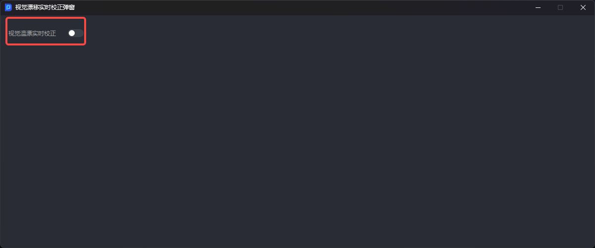
- Select [Real-time Vision Thermal Drift Correction] from the software menu bar.
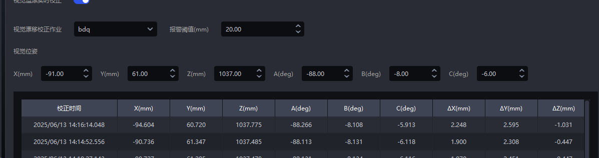
- In the pop-up window, turn on the [Real-time Vision Thermal Drift Correction] Switch, and configure [Vision Thermal Drift task], [Alarm Threshold], and [vision pose] (the value is the Picking Pose obtained by running the calibration sphere task in Step 1).
3. Correct the actual task
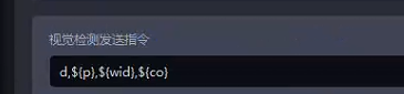
- The correction operation can only be triggered by the Robot. Configure [Vision Inspection Send Command] in the Robot configuration of the task to be corrected as follows. co=4 indicates triggering the calibration sphere run, which will calculate a drift offset.
You can configure the field
in_dtinPickWiz Send-to-Robot Command, which indicates whether the drift correction threshold check is passed. If it is within the threshold range or real-time vision drift correction is not enabled,in_dt=1; otherwise,in_dt=0.Test the correction effect
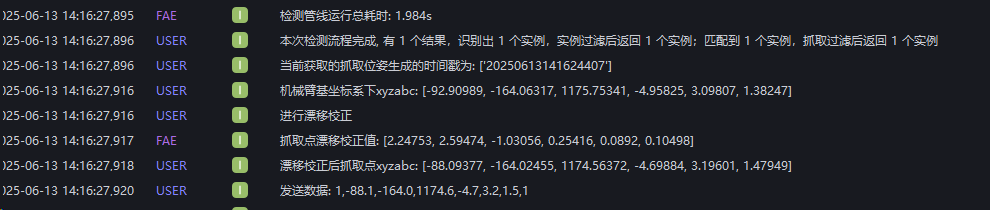
First turn off the vision thermal drift correction Switch, manually trigger the task to run, and record the current pose [representing the pose before the offset].
Then turn on the vision thermal drift correction Switch, trigger the actual workpiece task through the Robot, and obtain the pose after drift correction [with an error range within ±5mm].
Coordinates without compensation
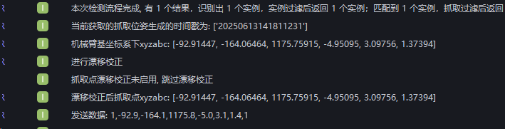
Coordinate values after compensation
4. Turn off the correction function
In the [Real-time Vision Thermal Drift Correction pop-up window], turn off the [Real-time Vision Thermal Drift Correction] Switch.
Notes:
Manually clicking run in the interface to trigger the calibration sphere task will not apply compensation. Compensation is applied only when it is triggered by the Robot and runs with the corresponding send command configured;
After the calibration sphere task is executed, if the Threshold is exceeded, all subsequent runs of other normal tasks will continue to alarm and send an exception signal to the Robot.
The logic is implemented as a custom on-site solution. The output signal when the Threshold is exceeded is '0,0,0,0,0,0,0'