Appendix
8.1 Product Specifications
| W1 Pro product specifications | ||
|---|---|---|
| Whole | Body Type | Full‑Body |
| Application Scenario | Autonomous Mobile Scenarios Typical Industries: Data Collection & Training, Research & Education, Commercial Services, Industrial Manufacturing | |
| Dimensions (L × W × H, Standing) | 682 mm × 550 mm × 1636 mm | |
| Weight | 107kg (slight variations exist across different versions) | |
| Total Degrees of Freedom | 34 | |
| Torso | neck:2 | Waist:2 | leg:2 | |
| Normal Operating Temperature Range | 0ºC ~ 40ºC | |
| Mobile Functions | Drive Type | Differential Drive |
| Chassis Degrees of Freedom | 2 | |
| Navigation Method | Laser SLAM | |
| SLAM Navigation Repeatability | ≤±20 mm,±2° | |
| Motion Directions | Differential Drive Chassis: Forward, Backward, In‑place Rotation | |
| Straight‑Line Speed | Rated Straight‑Line Speed: 0.75 m/s Recommended Operating Speed: 0.4–0.75 m/s (depending on working conditions) | |
| In‑place Rotation Speed | Maximum In‑place Rotation Speed: 75 deg/s Rated In‑place Rotation Speed: 60 deg/s (completes a 180° rotation within 3 s) | |
| Rated Passage Width | Chassis Width + 400 mm | |
| Gap Crossing Width | 30mm | |
| Obstacle Clearance Height | 10mm | |
| Climbing Capability | ≤ 3° | |
| Perception Functions | Head Vision | 6 cm baseline humanoid binocular pure vision + large model binocular algorithm |
| Head Vision Field of View | 90°*60° | |
| Robotic Hand Wrist Vision | Standard: None Optional: Wrist RGB‑D cameras installable on both hands | |
| Navigation LiDAR | 2 pcs, installed diagonally on the chassis | |
| Navigation & Obstacle Avoidance Cameras | 2pcs, installed at the front and rear center of the chassis | |
| Charging Functions | Battery Type | Lithium Iron Phosphate (LiFePO₄) |
| Battery Voltage | 48V | |
| Battery Capacity | 40Ah | |
| Charging Method | Manual Charging / Automatic Docking for Charging | |
| Rated Charging Current | 【HW 0.22】10A 【HW 0.23】35A | |
| Manual Charging Time(30% → 100%) | 【HW 0.22】≤4h 【HW 0.23】≤1.5h | |
| Automatic Docking Charging Time (30% → 100%) | 【HW 0.22】≤4h 【HW 0.23】≤1.5h | |
| Interaction Functions | Audio‑Visual Interaction | Available |
| LLM Voice Interaction | Standard | |
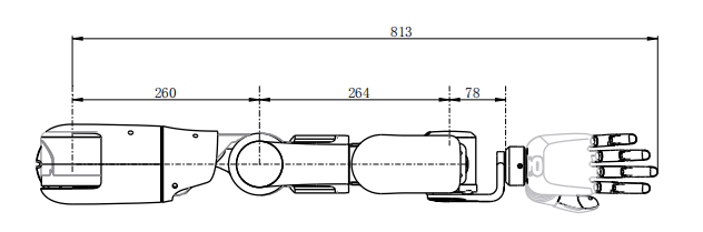
| Arm | Single Arm Degrees of Freedom | 7DOF (shoulder:3, in elbow:1, wrist:3) |
| Single Arm Rated Payload | 5kg | |
| Arm Repeatability (Parking Mode, excluding end‑effector) | ±2 mm | |
| Maximum Reach (excluding end‑effector) | 1612mm | |
| End Effector | End Effector Type | Default: Hand Optional: Gripper |
| Degrees of Freedom (per unit) | Hand: 6 DOF, human‑like five‑finger design | |
| Control Module | Battery Life (Stationary Operation Scenarios) | ≥8h |
| Computers and Computing Power | Standard dual‑PC architecture, ≥300 TOPS | |
| Other | High‑Frequency Motion Control | 1 kHz |
| Automatic Hand‑Eye Calibration | Available | |
| Intelligent OTA Upgrade | Available | |
| Secondary Development | Available | |
| Teleoperation | Available |
8.2 Hardware Specifications
8.2.1 Coordinate Systems, Joint Rotation Axes, and Joint Zero Positions
When all joints are at zero degrees, the coordinate system of each joint is as shown in the figure below.
| Component Name | Joint Axis | Coordinate System |
|---|---|---|
| Whole | 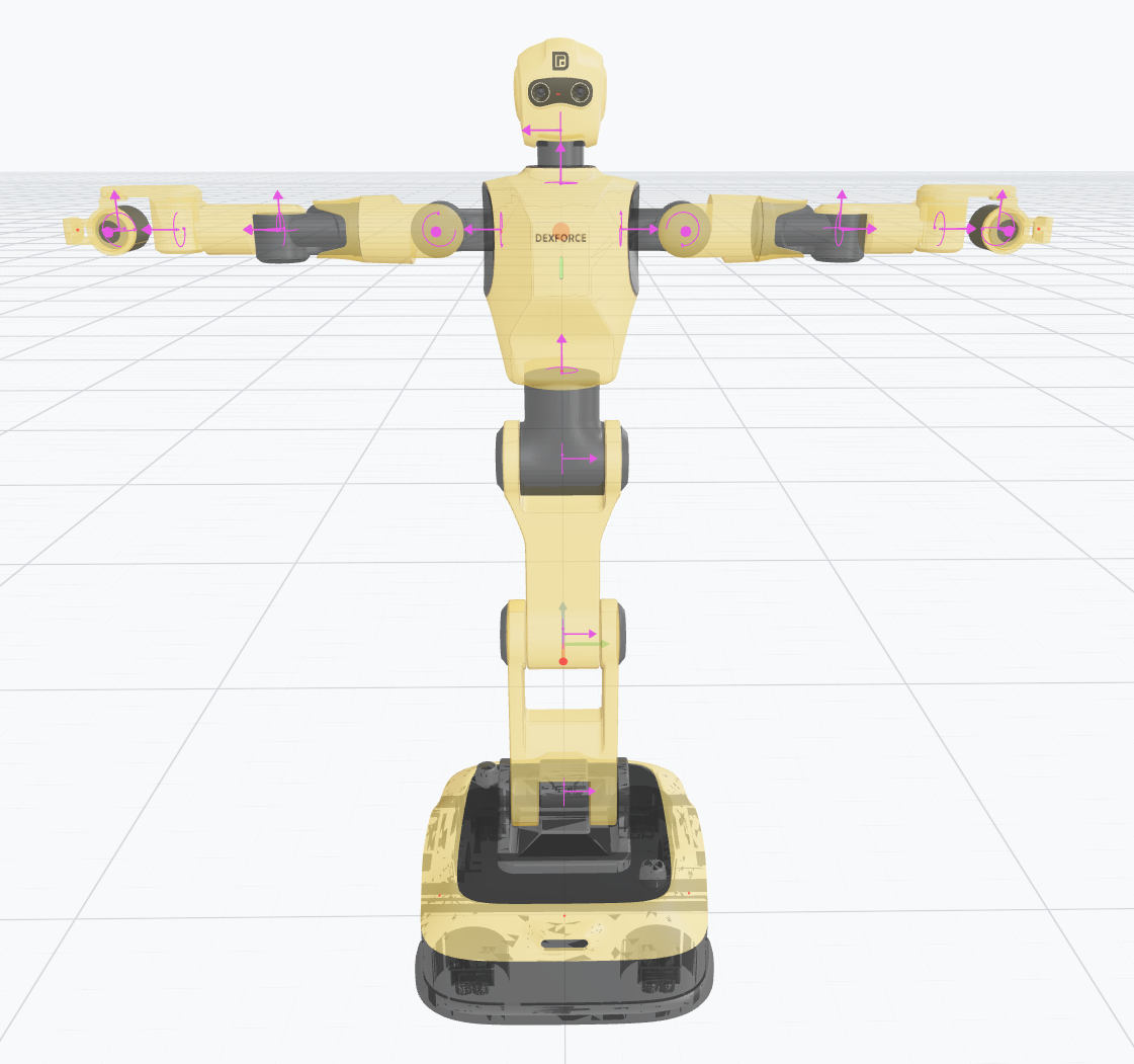 | 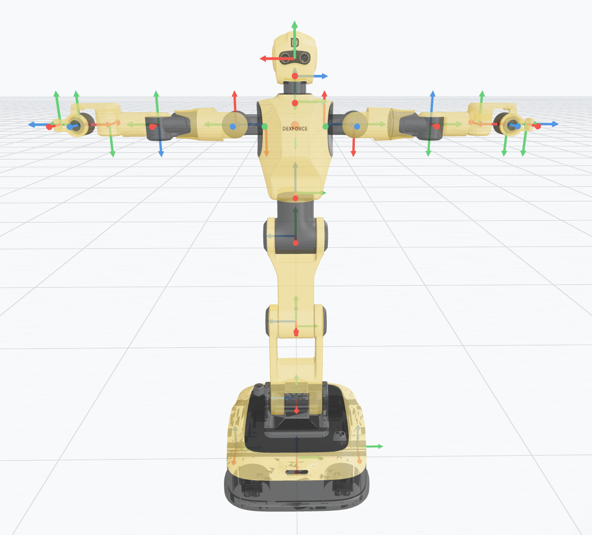 |
| Head | 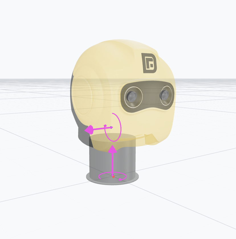 | 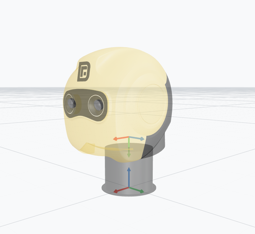 |
| Torso | 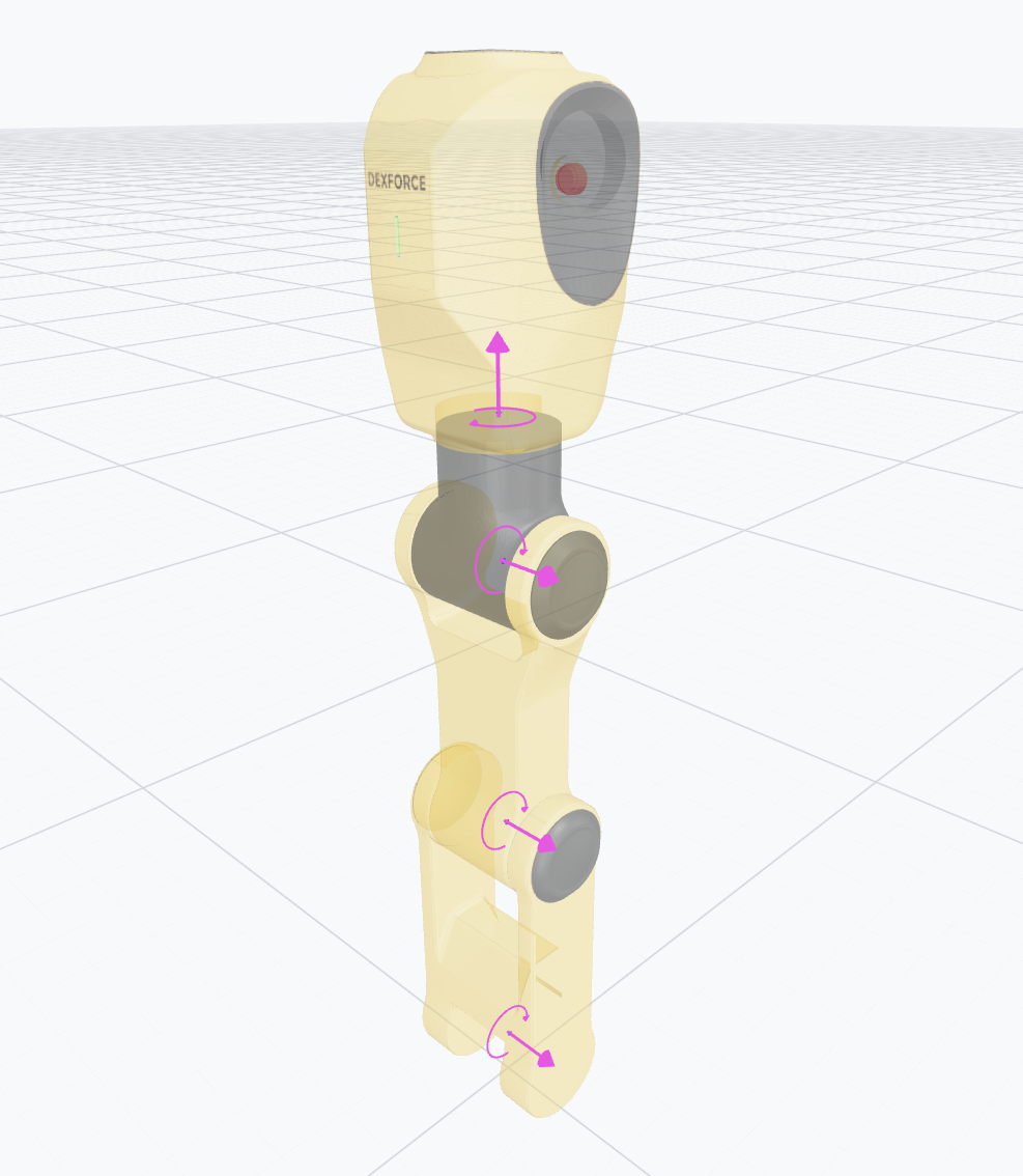 | 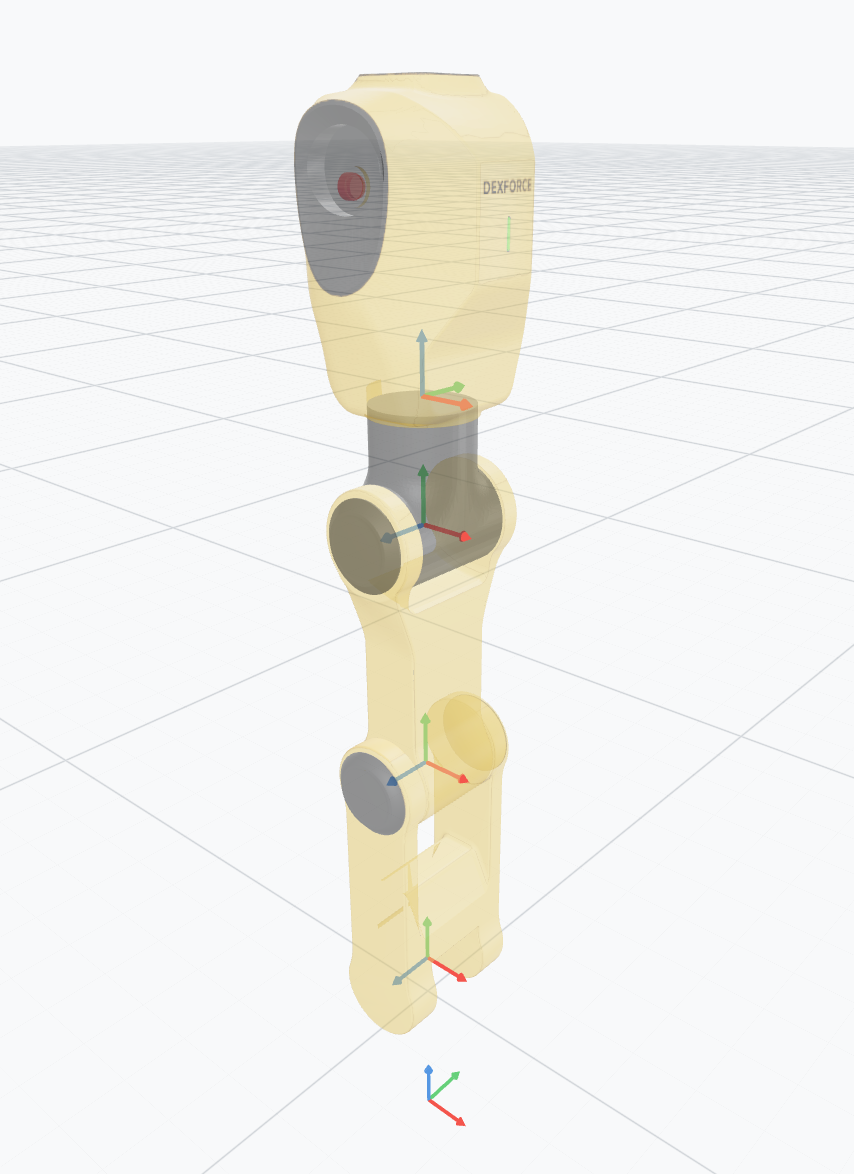 |
| Left Arm | 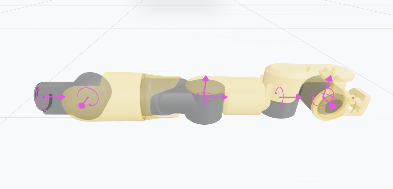 | 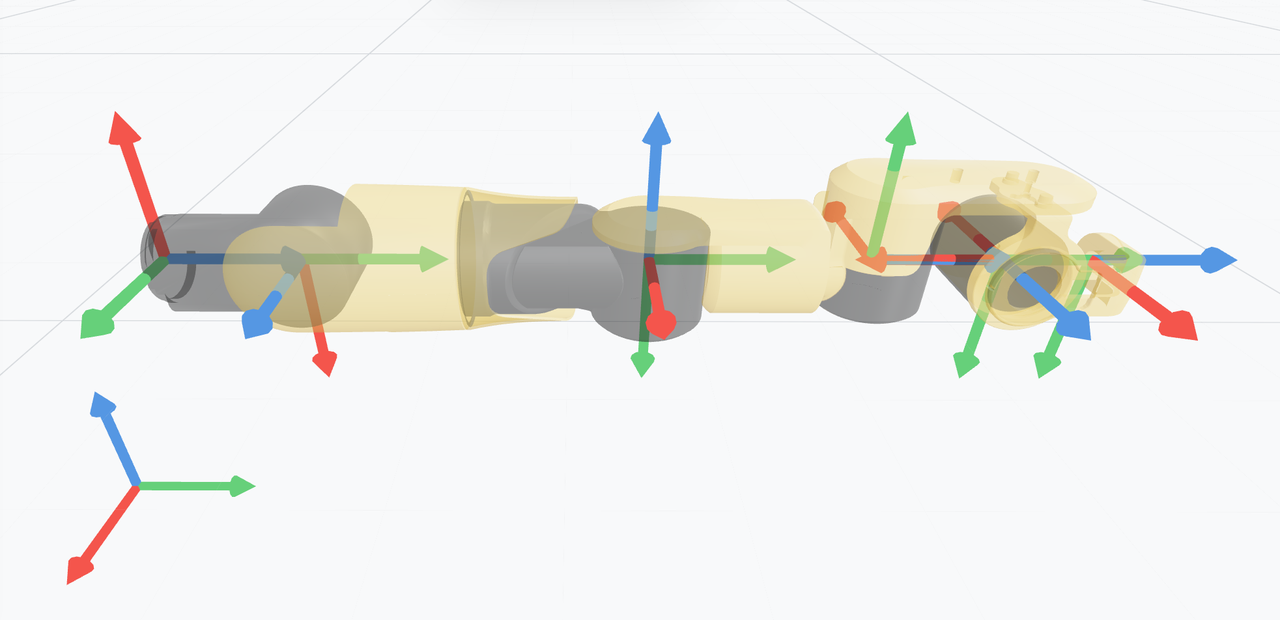 |
| Right Arm | 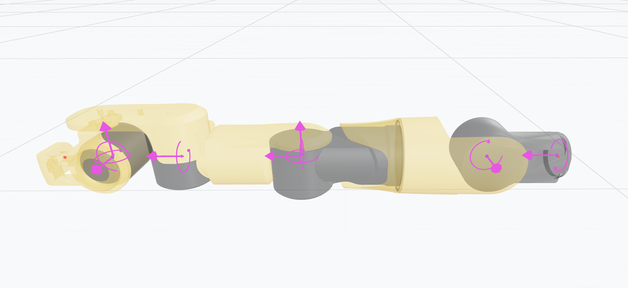 | 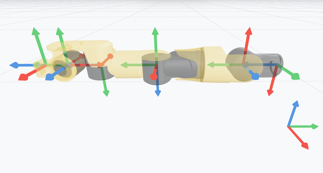 |
| Left End Effector | / | 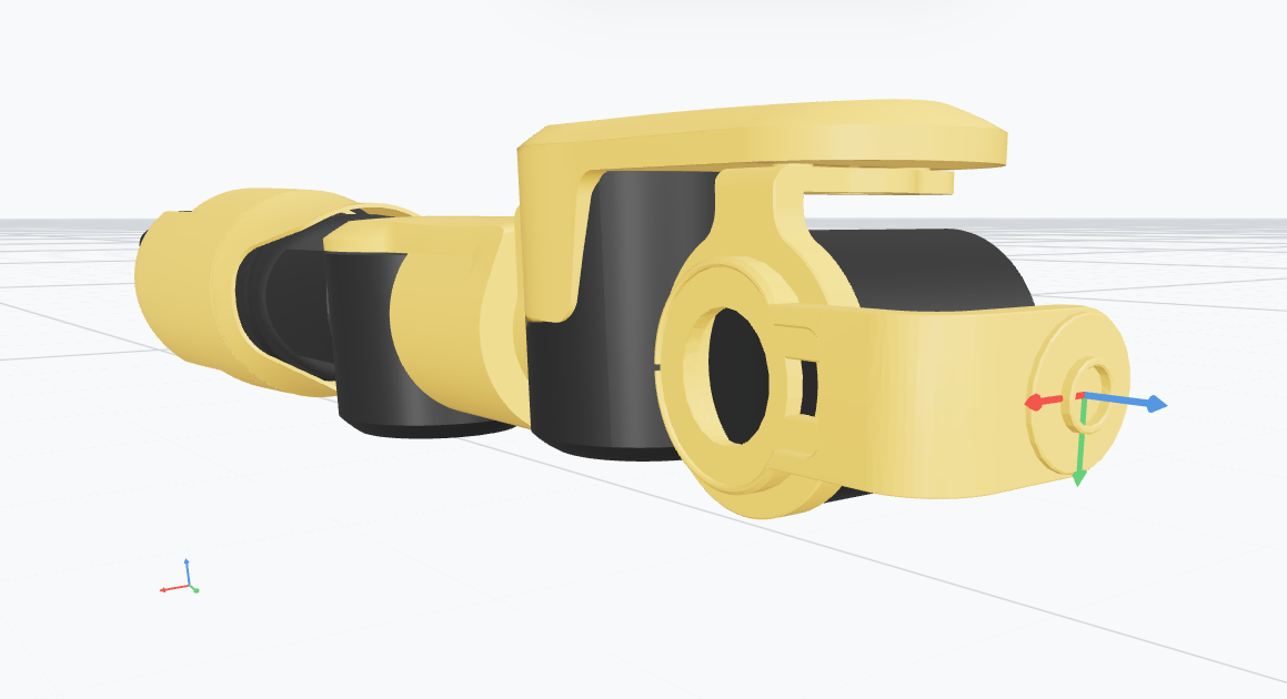 |
| Right End Effector | / | 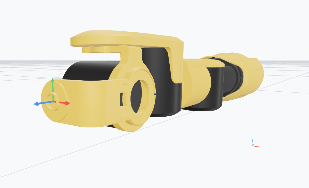 |
8.2.2 Full‑Body
| Full‑Body Pose | Diagrams |
|---|---|
| Standby Pose (Front View) | 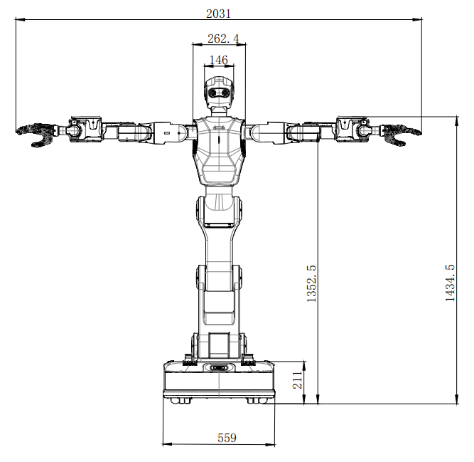 |
| Standby Pose (Side View) | 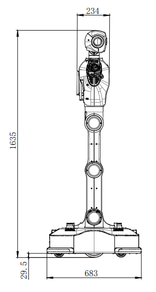 |
| Rest Pose (Front View) | 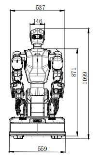 |
| Rest Pose (Side View) | 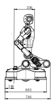 |
8.2.3 Neck
| Neck Pose | Diagrams |
|---|---|
| Zero Position | 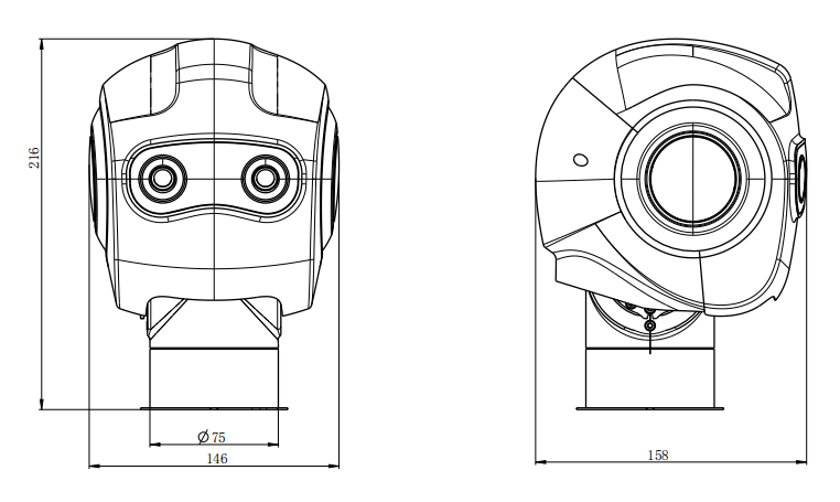 |
| Head Tilt Up (25°) | 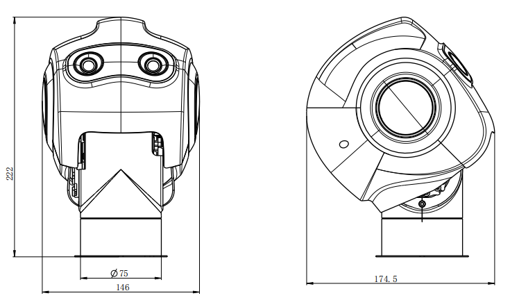 |
| Head Tilt Down (45°) | 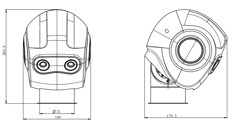 |
| Head Turn Left (90°) | 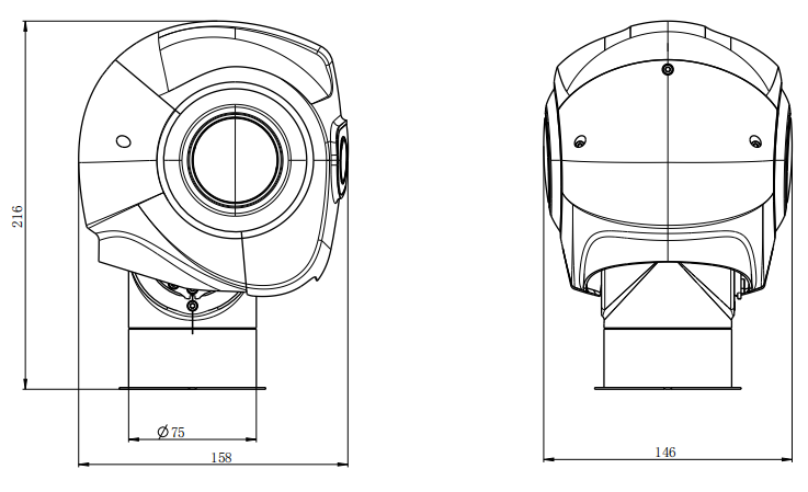 |
| Head Turn Right (90°) | 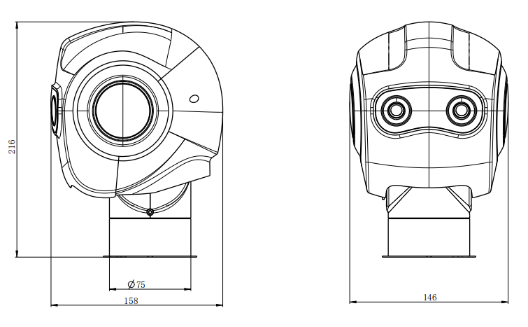 |
8.2.4 Torso
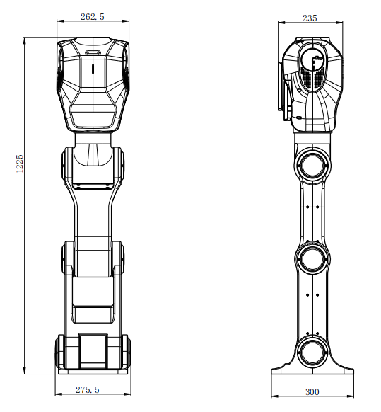
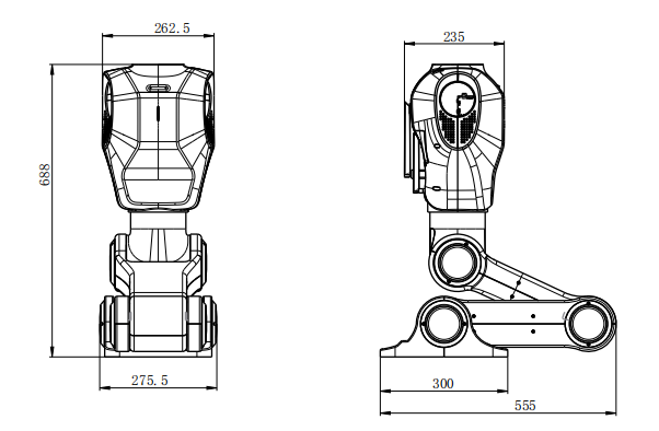
8.2.5 Arm
8.2.6 Hand and Gripper
| Hand | |
|---|---|
| Transmission Type | Linkage |
| Control Interface | CAN |
| Degrees of Freedom | 6 |
| Number of Joints | 6 active + 5 passive |
| Weight | 623.5 g |
| Maximum Grasping Payload | 28 kg |
| Tactile Sensing | Equipped |
| Operating Voltage | DC 24 V ± 10% |
| Standby Current | 0.2 A |
| Average Current (No‑Load Motion) | 0.75 A |
| Maximum Current | 1.4 A |
| Reset Positioning Accuracy | ±0.20 mm |
| Maximum Fingertip Force (Thumb) | 10 N |
| Maximum Fingertip Force (Four Fingers) | 8 N |
| Maximum Grasping Force (All Five Fingers) | 50 N |
| Gripper | ||
|---|---|---|
| Performance | Gripping Force (per side) | 40–140 N |
| Total Stroke | 50 mm | |
| Maximum Recommended Payload | 3 kg | |
| Open/Close Time | 0.75 s / 0.75 s | |
| Position Repeatability | ± 0.03 mm | |
| Operating Noise | < 50 dB | |
| Weight | 1 kg | |
| Mechanical | Transmission Type | Precision planetary gearbox + rack‑and‑pinion |
| Dimensions | 138.5 mm × 75 mm × 75 mm | |
| Flange Standard | Compliant with ISO 909‑1‑50‑4‑M6 standard flange | |
| Allowable Static Load (Vertical) | 300 N | |
| Allowable Moment Load | 7 N·m | |
| Electrical | Operating Voltage | 24 V DC ± 10% |
| Rated Current | 0.4 A | |
| Peak Current | 1.2 A | |
| Rated Power | 9.6 W | |
| Environmental | Recommended Operating Environment | 0–40°C, Humidity ≤ 85% RH |
| Protection Rating | IP 67 | |
| Functional Features | Adjustable Gripping Force | Supported |
| Adjustable Position | Supported (gripper position adjustable) | |
| Adjustable Speed | Supported (gripper motion speed adjustable) | |
| Drop Detection | Equipped | |
| Self‑Locking | Equipped | |
| Plug‑and‑Play | Supported | |
| Certifications | CE, FCC, RoHS |
8.2.7 Onboard Computer
| PC1 & PC2 | |
|---|---|
| Controller Model | PC1 & PC2 |
| Processor | Jetson Orin NX 16GB |
| Computing Performance | Super Mode: Up to 150 TOPS |
| Memory | 16 GB |
| Storage | 1 TB |
| Wired Network | Gigabit Ethernet Port × 2 |
| Wireless Network | Wi‑Fi |
8.3 Environmental Requirements
To ensure normal operation, successful task execution, proper charging, and a guaranteed service life of the robot, the environmental, climatic, and floor conditions for its use must be clearly defined. This includes requirements for both the operational and charging areas.
8.3.1 Floor Conditions
A well‑maintained floor environment enables more stable robot operation and reduces the wear rate of various components, including LiDAR sensors, wheels, and motors. The following floor technical requirements are established:
8.3.1.1 Floor Evenness
When the floor unevenness is below the maximum allowable value, the robot shall be capable of controlled travel at rated speed. Unevenness is defined as the maximum height difference within a reference area (different project requirements may necessitate different floor specifications). If the unevenness exceeds the maximum allowable value, the robot's capability shall be evaluated based on the specific model and project conditions.
Special Environment: The maximum allowable unevenness within a 2.25 m² area shall be ≤ ±2 mm.
8.3.1.2 Floor Slope
Short‑range slope (H/L): Defined as the maximum ratio of the vertical height difference to the horizontal distance over a 100 mm length. The maximum allowable short‑range slope shall be ≤ 0.05 (H = L·sin3°). For parking positions requiring precise robot positioning and docking, the slope shall be ≤ 0.017 (H = L·sin1°).
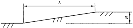
Long‑range slope: When the floor slope is below the maximum allowable value, the robot shall be capable of controlled travel at rated speed. The maximum slope angle is 3°. The robot can traverse slopes in both forward and backward directions, with a climbing speed ≤ 0.4 m/s. The maximum slope length is 5000 mm.
8.3.1.3 Step Height
Step height is defined as the maximum vertical height difference over a 1000 mm length, as shown in the figure. When the step height is below the maximum allowable value, the robot shall be capable of controlled travel at rated speed. However, step heights are not permitted at robot parking positions. Step heights represent a special operational scenario; the robot is capable of traversing such steps, but prolonged operation under these conditions is not recommended to ensure stability. The robot can traverse steps in the forward direction. The maximum step height is 10 mm, with a maximum allowable value of 10 mm and an obstacle‑clearance speed ≤ 0.4 m/s.
8.3.1.4 Gap Width
Gap width is defined such that when the gap is below the maximum allowable value, the robot shall be capable of controlled travel at rated speed. However, gaps are not permitted at robot parking positions. The maximum allowable gap width is 30 mm, with a traversing speed ≤ 0.4 m/s.
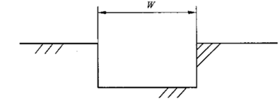
Friction Coefficient: The floor friction coefficient is critical for braking distance and positioning accuracy. Floor joints, debris, liquids, cleaning agents, and compounds may impair the robot's mobility. The friction coefficient shall be ≥ 0.5 (free of standing water, oil, sand, or other substances that may reduce friction).
ESD Requirements: For environments requiring electrostatic protection, the floor surface or volume resistance shall be in the range of 2.5×10⁴ to 1.0×10⁸ Ω, and the flooring shall exhibit fire resistance, environmental compatibility, and wear resistance.
8.3.2 Navigation Environment
The robot uses SLAM technology for localization and navigation, characterized by high precision, zero cumulative error, high robustness, and strong dynamic environment perception. To ensure proper navigation performance, the following environmental requirements must be met:
LiDAR Reflectivity: Ensure that the reflectivity of equipment and wall surfaces is greater than 10%.
Avoid Specular Features: Avoid large areas of specular surfaces within the LiDAR field of view, as they may interfere with navigation.
Open Space: Ensure the area is open enough for the robot to localize using LiDAR. If the LiDAR cannot detect objects in its field of view, the robot will be unable to navigate effectively, potentially leading to derailment or collisions.
Avoid Low Walls: At the LiDAR operating height (10–30 cm above the floor), ensure there are no low‑wall top surfaces. Since LiDAR cannot be perfectly horizontal, low walls may cause mapping or navigation failures or reduced accuracy.
Avoid Rapidly Changing Obstacles: Minimize environments with a large number of rapidly changing obstacles, such as tidal‑flow equipment or shelving, as they may affect navigation accuracy.
Avoid Long Corridors: Ensure that corridor lengths do not exceed 30 meters without distinguishable features on both sides, to prevent navigation failures or reduced accuracy.
8.3.3 Operating Environment
To ensure normal robot operation, the following operating environmental conditions shall be satisfied:
Site Safety: The site environment variation rate shall be controlled within 30%, and floors shall be regularly cleaned and maintained with obstacles removed.
Temperature and Humidity: Temperature shall be in the range of 0°C to 40°C, and relative humidity in the range of 20% to 80%.
Air Quality: The environment shall be free of dust, flammable, explosive, and corrosive gases.
ESD Requirements: Floor materials shall facilitate electrostatic discharge.
Altitude: Altitude shall not exceed 1000 m.
Lighting: Ambient light intensity shall be less than 2000 lux, with no direct sunlight exposure.
Electromagnetic Interference: In environments with strong electromagnetic interference, it must be confirmed in advance that the robot's normal operation is not affected.
Other: Keep the robot away from corrosive gases, heaters, or heating elements.
8.3.4 Aisle Environment
To ensure safe and stable long‑term robot operation within aisles, the following requirements must be met:
Aisle Width: Aisle width shall be considered over the entire aisle, taking into account the actual clear width after removing obstacles on both sides. Ensure sufficient space for the robot to navigate without collisions or obstructions.
Aisle Length: Aisle length should not be excessive to avoid long‑corridor situations, which may lead to localization drift or navigation failures.
Avoid Tidal‑Flow Equipment or Shelving: Avoid large‑scale tidal‑flow equipment or shelving in aisles. Movement of such items may interfere with the robot's travel, affecting navigation accuracy and stability.
8.3.5 Charging Environment
To ensure proper robot charging and long‑term stable operation, the following charging environment requirements shall be met:
Cleanliness of Operating Area: The floor in the robot's operating area shall be regularly cleaned and maintained to ensure a clean environment during charging and prevent external interference or damage.
Maintenance Access: A maintenance access path at least 1 meter wide shall be reserved around the charging area to facilitate access and operation by maintenance personnel.
Clearance Around Charging Area: No obstacles shall be placed within 2 meters of the charging area to ensure the robot is free from obstructions or hazards during charging.
Avoid Highly Reflective Objects: Highly reflective objects should be avoided in the charging area to minimize interference with charging equipment and the robot.
Charging Area Placement: The charging area shall be located near a wall and away from high‑variation‑rate areas, such as temporary storage zones, to ensure a stable charging environment.
Supply Voltage and Frequency Compliance: The supply voltage and frequency must comply with the technical specifications of the charging station to ensure proper operation.
Power Supply Margin: The power supply capacity shall exceed the maximum operating power of the charging station, with a margin of at least 20% to accommodate sudden loads and fluctuations.
Low‑Impedance Grounding: The power supply circuit must provide a low‑impedance grounding path to ensure safe operation of the charging equipment.
Overvoltage, Overload, and Leakage Protection: The power supply circuit must be equipped with overvoltage, overload, and leakage protection to safeguard the charging equipment and the robot against power fluctuations and safety risks.
8.3.6 Network Environment
The robot communicates with the host system via a wireless network to receive tasks. The network environment is critical for normal operation and connectivity. The following network requirements are essential for smooth robot operation:
Stable Network Connection: The robot is equipped with an integrated Wi‑Fi module or WLAN gateway. If using a wireless connection to the internet, ensure proper router configuration. It is recommended to use the 5 GHz wireless channel. If the wireless network is unstable or bandwidth is insufficient, use the WAN interface for wired internet access.
Network Bandwidth: Ensure sufficient bandwidth to meet operational requirements, with a minimum of 200 Mbps in both uplink and downlink directions.
Low Latency: Network latency should be maintained within 200 ms to ensure timely response to commands and environmental changes.
Compatibility: Support for mainstream Wi‑Fi protocols (802.11a/b/g/n/ac/ax) is required.
Reliability: Network equipment and connections must be highly reliable to prevent unexpected interruptions or disconnections that could affect normal robot operation. Therefore, a wired connection is recommended whenever possible.