Advanced Software Features
This section describes the advanced features of the W1 Pro robot. These operations must be performed by personnel trained by Cross-Dimensional Intelligence.
4.1 Chassis Mapping and Navigation
4.1.1 Mapping
For handle usage instructions, please refer to the Control Handle section.
4.1.1.1 Stopping the Navigation Service
Execute the following command on PC1 to stop the navigation service:
sudo systemctl stop dexe-auto.service dexe-auto.timer dexe-map.service4.1.1.2 Starting the Mapping Service
In the remote desktop terminal, enter the following command to start the mapping service:
To view the log output:
4.1.1.3 Setting the Map Name and Starting Mapping
4.1.1.4 Opening the Mapping RViz on PC1
Execute the following command on PC1 to open the mapping RViz interface:
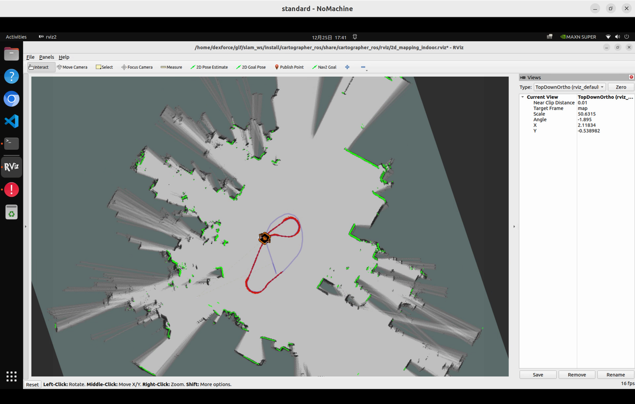
rviz2 -d /home/dexforce/w1/install/cartographer_ros/share/cartographer_ros/rviz/2d_mapping_indoor.rvizRemote Control Mapping
- At this point, you can use the handle to remotely control the robot's movement for mapping. The mapping result is shown in the figure below.
- Saving the Map After Mapping Completion
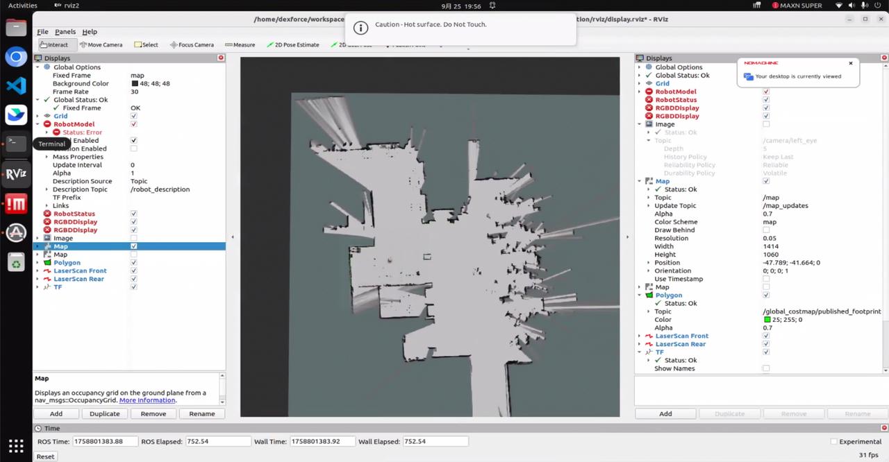
4.1.1.5 Viewing the Saved Map Results
Copy the results from the mapping directory to your local machine to view them:
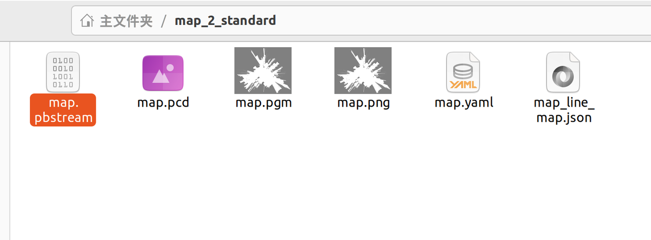
Check the folder. It should contain the following map files, as shown in the figure below:
- Evaluate the mapping result
If there is no ghosting and no mapping errors, the map is considered suitable for navigation.
4.1.1.6 Stopping the Mapping Service
4.1.2 Navigation
4.1.2.1 Restarting the Navigation Service
Stop the mapping service and restart the navigation service.
4.1.2.2 Enabling Visualization (PC2)
The TF tree can be started using the following command on PC2 (if the visualization interface is already enabled on PC2, this indicates that TF has already been started).
4.1.2.3 Starting the Navigation Node (PC1)
After restarting the navigation service, the navigation node will start automatically.
During navigation, if you intend to use a previously built map, you can switch the current map using the map_manager service calls.
View all available map files.
Switch to the desired map.
4.1.2.4 Navigation Visualization
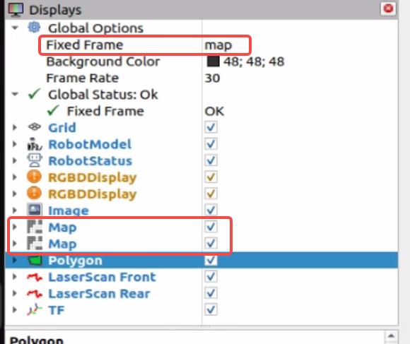
- In the upper-left corner of the PC2 visualization interface, change the "Fixed Frame" to "map". Then, check the first and second "Map" options, as shown in the figure below.
- After checking these options, the visualization interface will appear as shown in the figure below.
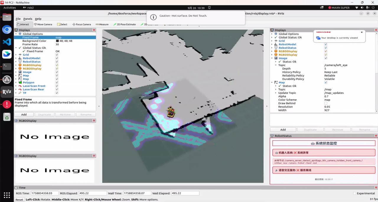
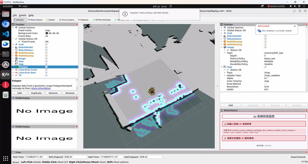
Upon startup, the system will attempt self-localization. If the laser point cloud does not align with the obstacles in the map, it indicates that the robot has not been successfully localized.
- Remote Localization
At this point, use the handle to remotely control the robot to rotate in place. When the point cloud aligns with the obstacles (i.e., the colored point cloud overlaps with the black obstacle representation), localization is successful, as shown in the figure below.
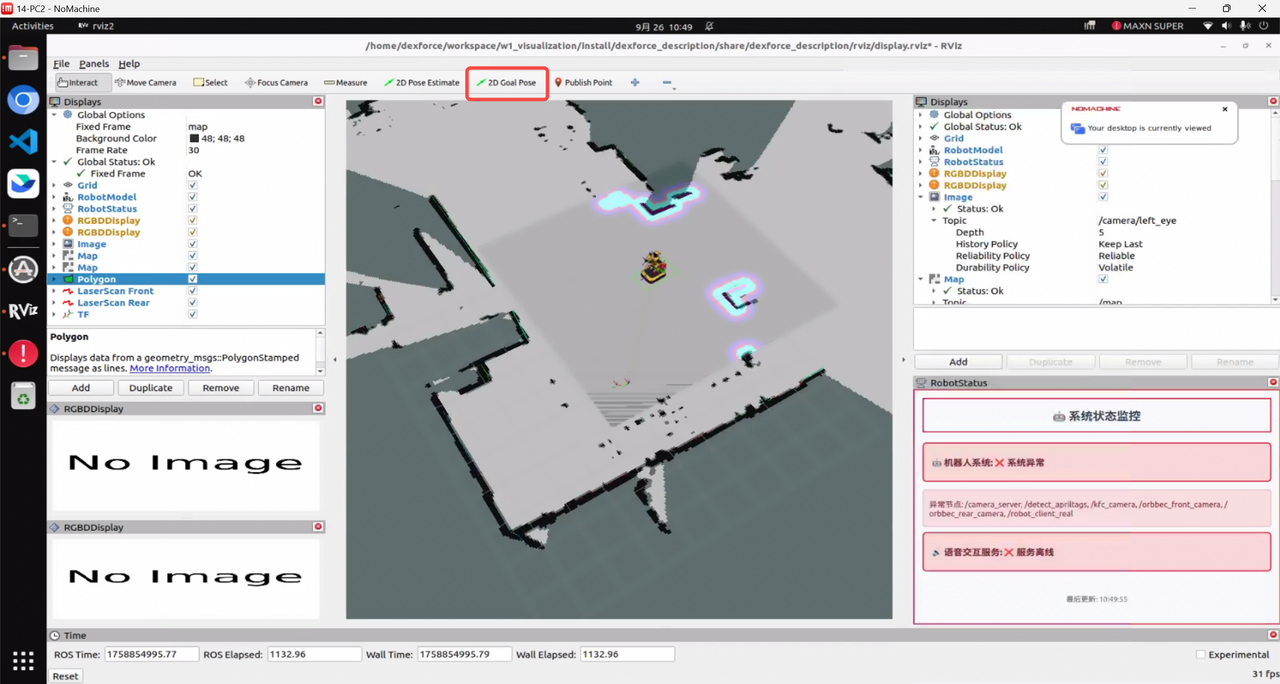
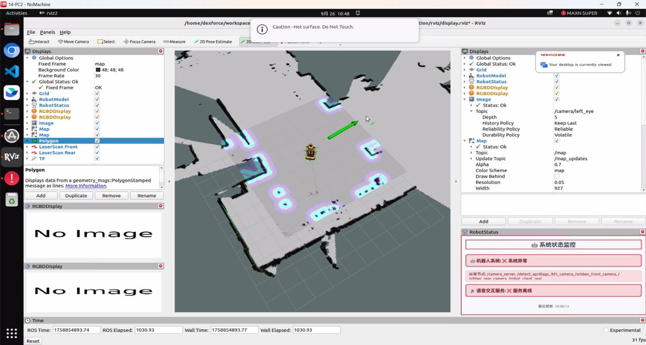
- Then, click "2D Goal" in RViz to send a target point, including both position and orientation. The orientation is indicated by an arrow, as shown in the figure below.
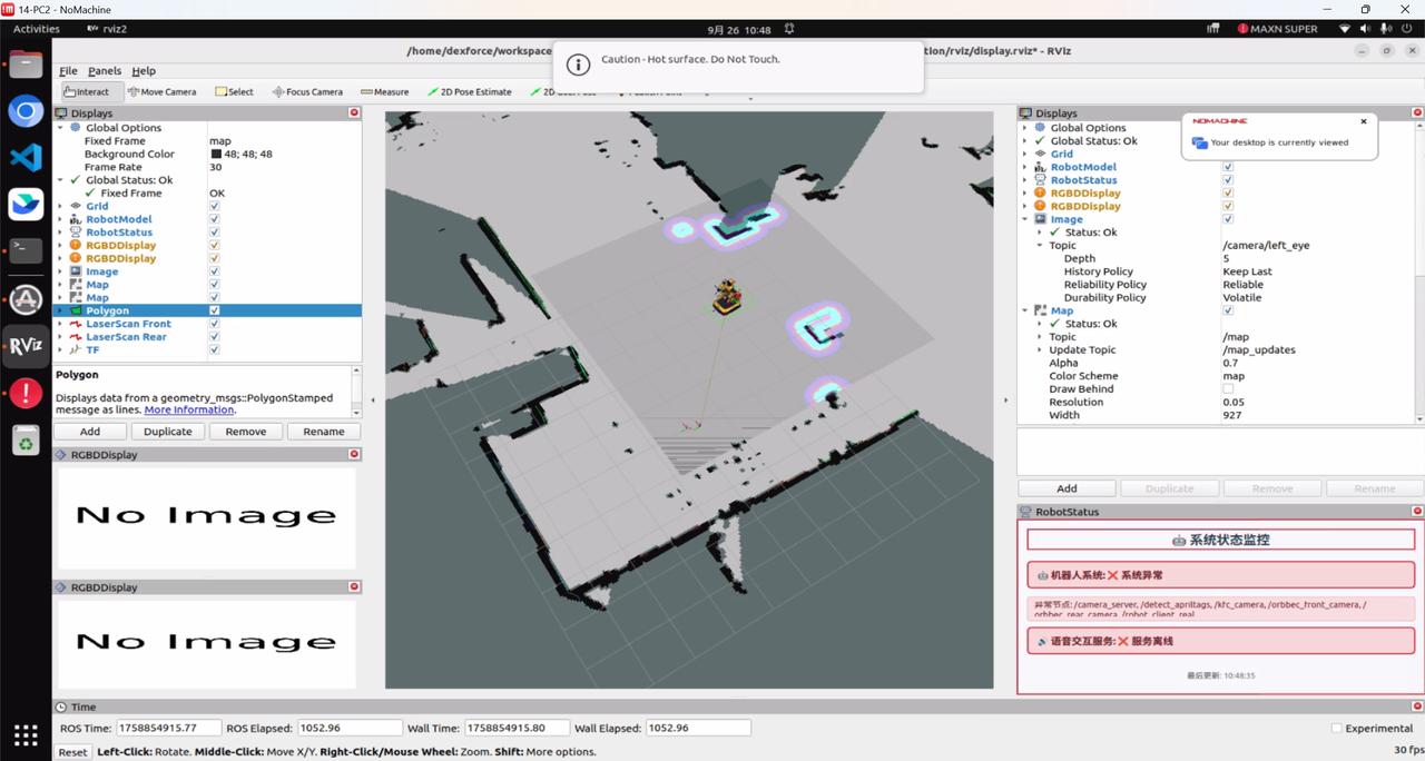
After successful navigation, the robot will arrive at the target point, as illustrated in the figure below.
4.1.3 Common Anomalies: Diagnosis and Solutions
After clicking the navigation target in the RViz visualization interface, the robot does not move.
- Check whether the handle node is still printing information. If such information is present, it indicates that the handle control node has not been closed, and the handle is still sending zero velocity commands, which conflicts with the navigation velocity commands. The solution is to press the Start button on the handle to stop the handle control node from publishing velocity commands.
Localization fails for an extended period, and the localization terminal output displays IMU-related content, as shown in the figure below. This indicates that the IMU data stream has been interrupted. The solution is to restart the IMU publishing node.
The navigation node fails to start and only outputs partial content. This is caused by incomplete termination of the previous ROS-related nodes. The solution is to fully terminate all navigation-related nodes and then restart the navigation node.
4.1.4 Automatic Docking for Charging
Automatic docking for charging refers to setting a fixed charging position to which the robot can automatically return when the battery level is low. This charging method is specifically applied in "mobility + manipulation" scenarios, such as industrial settings, Guangdong data collection, and JD Logistics.

4.1.4.1 Prerequisites
Before performing automatic docking for charging, ensure that the robot has successfully completed mapping and generated a complete map, enabling the robot to recognize its environment.
Before performing automatic docking for charging, the navigation function must be enabled so that the robot can autonomously navigate to the charging station.
4.1.4.2 Switching to Automatic Mode
The automatic docking function is only effective in Automatic Mode. The robot must be in Automatic Mode to receive system tasks and perform automatic docking. If the current mode is Teleoperation Mode, Mapping Mode, or any other mode, switching to Automatic Mode is required.
- Temporarily switch to Automatic Mode (reverts to the original mode after reboot)
Execute the following command in the PC1 terminal:
/home/dexforce/w1/dexe_mobile_application/script/change_mode.sh auto- Set Automatic Mode to start automatically on boot (remains in Automatic Mode after reboot)
Execute the following command in the PC1 terminal:
/home/dexforce/w1/dexe_mobile_application/script/change_mode.sh auto start4.1.4.3 Relocalizing the Robot
Before setting the charging docking point, the robot must be relocalized on the map to ensure that its localization is accurate. Otherwise, the coordinates of the subsequently set charging point will be incorrect.
- After the robot is powered on, it automatically completes localization by comparing the current sensor data with the existing map. In the RViz2 visualization interface, successful localization is indicated when the point cloud obtained from the LiDAR completely aligns with the contours of the map.
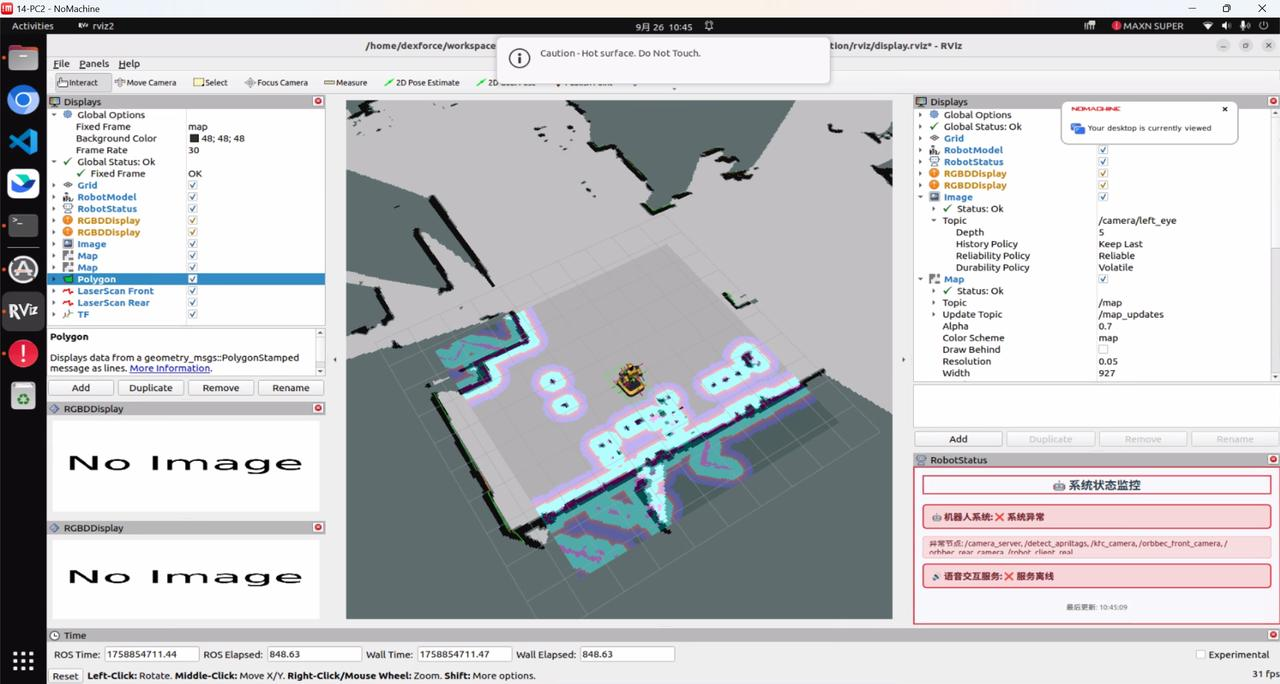
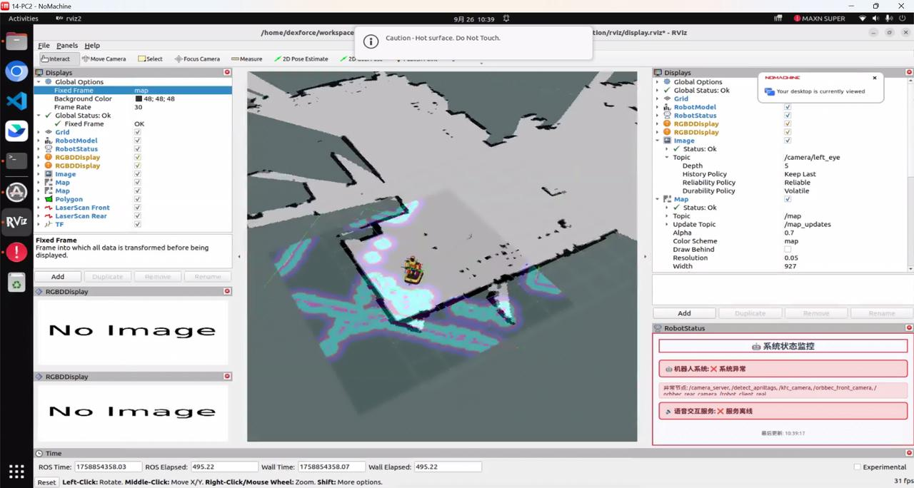
- If the RViz2 visualization interface shows an incorrect position or drift, it indicates that the robot has not been automatically localized successfully. In this case, manual remote control is required: move the robot a short distance and rotate it in place until the point cloud fully aligns with the map contours. As shown in the figure below, the point cloud does not align with the obstacles in the map.
4.1.4.4 Setting the Charging Docking Point
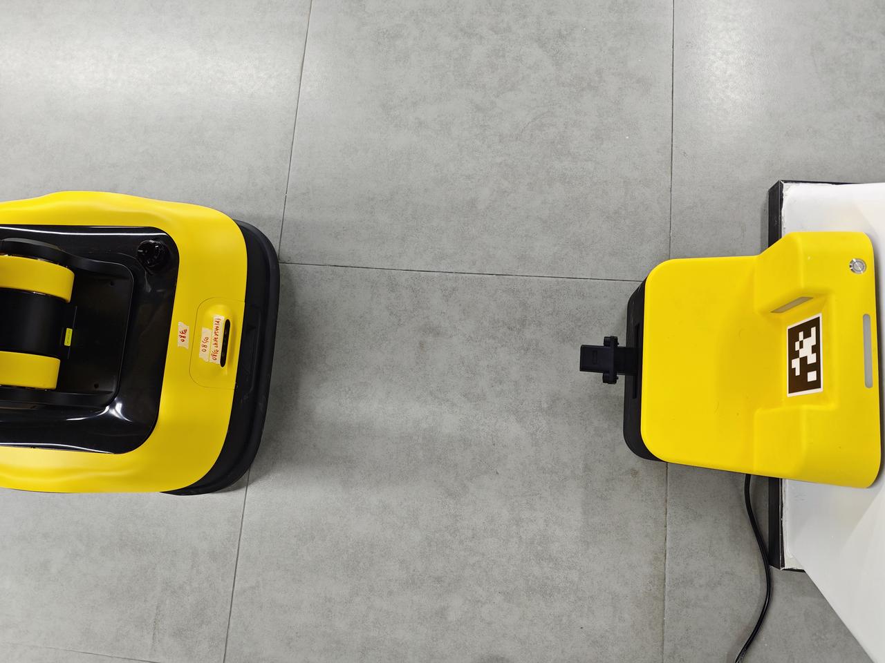
- Use the handle to remotely control the robot, moving it to a position 0.7 m to 1 m directly in front of the charging station, as shown in the figure below.
When setting the charging docking point, ensure that the charging station is permanently fixed. If the charging station is moved, the charging docking point must be reconfigured.
- Open a terminal on PC1 and execute the following command to obtain the robot's current position on the map and save this position as the charging docking point.
Ensure the robot is completely stationary; otherwise, the saved position coordinates may be inaccurate.
cd ~/w1 && source install/setup.bash && ros2 run mobile_perception create_charging_pose.py- Execute the following command to enable the automatic docking function, record the current position as the charging docking point, and start background monitoring. The system will continuously monitor the battery level.
ros2 service call /auto_charging std_srvs/srv/Trigger "{}"4.2 Teleoperation Instructions
4.2.1 Touch Plus Controllers Instructions
The Oculus Quest 3S is used for teleoperation. It consists of a head-mounted VR device and two handheld remote controllers. The button functions for the left and right remote controllers are described below:
Note:
The VR headset and its controllers are paired on a one-to-one fixed basis and are not interchangeable. Mixing different headsets and controllers is not allowed.
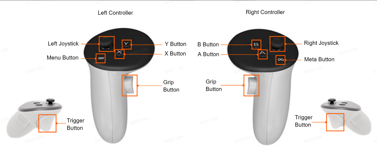
| Button | Button Operation | Description |
|---|---|---|
| Left/Right Joysticks | Left joystick forward / backward | When the leg motion mode is set to joystick lift/lower, controls the robot's legs to move straight up and down. |
| Left joystick left / right | In chassis differential drive mode, controls the robot chassis to rotate left or right in place. | |
| Right joystick forward / backward | In chassis differential drive mode, controls the robot chassis to move forward or backward. | |
| Single click left joystick | Activates data recording. | |
| Click left joystick again | Stops data recording. | |
| Single click right joystick | Deletes the previously recorded data segment. | |
| Click right joystick again | Deletes the previously recorded data segment. | |
| X Button | Single click X button on the left controller | Toggles the gesture of the left hand. |
| Y Button | Single click Y button |
|
| A Button | Single click A button on the right controller | Toggles the gesture of the right hand. |
| B Button | Single click B button on the right controller | Toggles the chassis between Parking Mode and Differential Drive Mode. When currently in Parking Mode: Single click B button → switches to Differential Drive Mode. Single click B button again → switches back to Parking Mode. |
| Meta Button | Short press Meta button | – After the VR headset is powered on, single click the Meta button to exit the current application and return to the VR headset home interface. – During full-screen VR teleoperation, single click the Meta button to display the hidden app bar, from which you can open the VR interface in a browser. Press again to hide the app bar. |
| Long press Meta button | When the VR desktop view is abnormal, long press the Meta button to reset the VR view. The VR desktop will return to the user's forward-facing position (normal view). | |
| Trigger Button | Single click left trigger button | Controls the grasp of the left hand. |
| Single click right trigger button | Controls the grasp of the right hand. | |
| Grip Button | Press and hold both grip buttons simultaneously | Pressing and holding both grip buttons simultaneously enters teleoperation mode. |
| Release both grip buttons | Releasing either grip button immediately exits teleoperation mode. After exiting teleoperation mode, to re-enter teleoperation, it is recommended to first long press the Meta button to reset the view, then press and hold both grip buttons simultaneously to re-enter teleoperation. | |
| Press and hold both grip buttons + move both arms | The robot's arm movements mirror the user's real-world actions. If a robot joint reverses abnormally, immediately spread both arms outward to the sides → rotate the wrist in the opposite direction of the abnormal movement until the robot arm is corrected → continue teleoperation. | |
| Press and hold for 3 seconds: Press and hold both grip buttons simultaneously + perform torso movements | Controls the robot's torso joint movements, such as crouching/standing up, left/right waist rotation, and forward/backward leaning (currently not supported). | |
| Press and hold for 3 seconds: | Left controller X button + right controller A button (press and hold for 3 seconds) | In head-mounted VR mode, when teleoperation has not started and data recording is not active, this returns to the mode selection interface. |
4.2.2 Switching to Teleoperation Mode
The factory default setting enables Automatic Mode on startup. To switch to Teleoperation Mode, follow the manual steps below.
- Execute the following command in the PC1 terminal to check the current mode:
systemctl status dexe-tele.service #查看遥操模式状态If the output contains active (running), the robot is currently in Teleoperation Mode.
If the output contains inactive (dead), the robot is currently not in Teleoperation Mode.
If the message Unit not found is returned, the command may have been entered incorrectly.
- If the robot is not currently in Teleoperation Mode, execute the following command in the PC1 terminal to temporarily switch to Teleoperation Mode (the mode will revert to the original setting after reboot):
cd /home/dexforce/w1/dexe_mobile_application/script
./change_mode.sh tele- If the robot is not currently in Teleoperation Mode, execute the following command in the PC1 terminal to set Teleoperation Mode to start automatically on boot (the robot will remain in Teleoperation Mode after reboot):
cd /home/dexforce/w1/dexe_mobile_application/script
./change_mode.sh tele start
4.2.3 VR Headset Connection
Note:
When using a USB signal amplifier for long-distance wired teleoperation, do not place the USB signal amplifier too close to the power adapter. A minimum separation distance of 20 cm is recommended.
If the USB signal amplifier is placed directly against the power adapter, communication through the robot chassis's external USB ports (2.0/3.0) may be interrupted.
- Wired connection between the VR headset and PC1: Use a USB data cable. Connect one end to the VR headset interface and the other end to a USB port under PC1 located at the rear of the robot chassis.
Warning:
When using a wired connection to the VR headset, be aware of the risk of dragging the chassis.
- Wi-Fi connection between the VR headset and PC1: After powering on the VR headset, single click the Meta button to enter the VR desktop. Move the controller to position the cursor over the app bar at the bottom of the VR desktop, press the trigger button, and click the Settings icon to connect to the desired Wi-Fi network.
Note:
When using a Wi-Fi connection, the robot's motion latency is relatively high. Frequent use of this method is not recommended.
If the app bar is not visible at the bottom, briefly press the Meta button on the right controller.
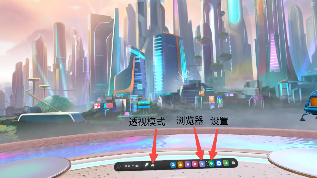
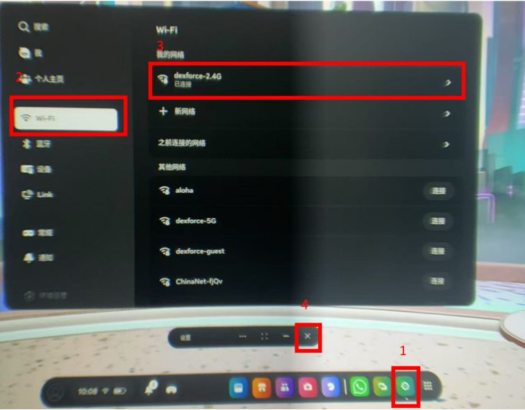
4.2.4 Entering Teleoperation
Power on the VR headset and single-click the Meta button to enter the VR desktop. You can see the VR desktop through the VR headset. If the VR desktop view is not properly oriented, long-press the Meta button to reset the VR view so that the VR desktop is positioned directly in front of the user.
Naturally extend both arms forward, keeping the arm positions aligned with those of the robot's arms.
Note: Excessive downward wrist extension may cause the controllers to move outside the visual tracking range of the VR headset.
- Move the controller to position the cursor over the Browser icon in the app bar, press the trigger button, and click to open the browser.
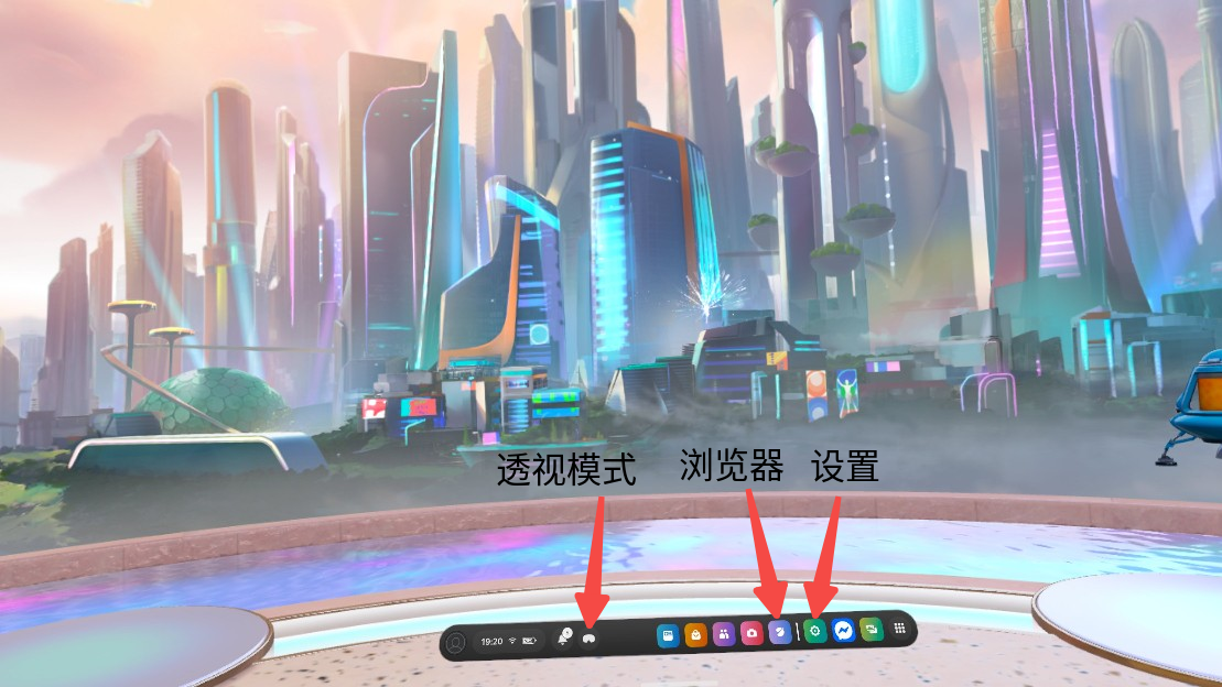
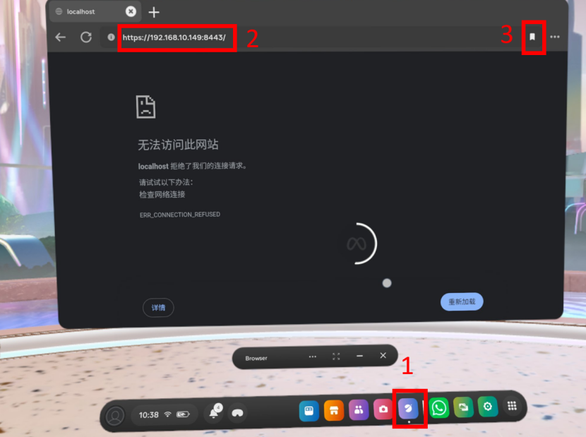
After opening the browser, move the controller and enter the following URL in the address bar to open the mode selection interface:
For wired VR headset connection: Enter
https://localhost:8443/For Wi-Fi VR headset connection: Enter
https://192.168.158.XX:8443/(This address is the robot's external network IP, which varies depending on the network to which it is connected—i.e., the IP address assigned to the robot by your local network. You can check the current external IP of PC1 by opening a terminal on your personal computer and entering theifconfigcommand.)Save the URL for future use. Subsequently, you can access it directly via the bookmark (located within the three-dot menu in the upper-right corner).
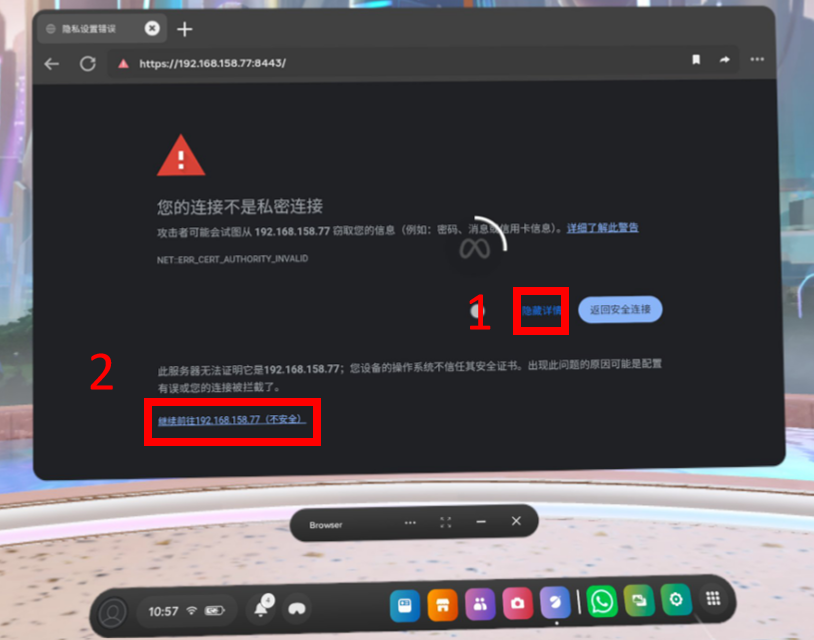
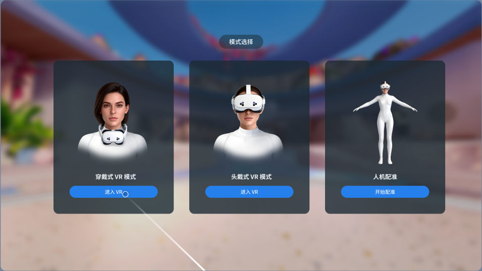
The mode selection interface offers three modes: Wearable VR Mode, Head-Mounted VR Mode, and Human-Robot Calibration. Click "Enter VR" / "Start Calibration" with the trigger button to enter the corresponding teleoperation mode.
Wearable VR Mode: The user wears the VR headset around the neck to teleoperate the robot. In this wearing style, the user's line of sight naturally faces forward, and the chassis is in a blind spot below the user's field of view. Therefore, Wearable VR Mode is suitable for scenarios that do not require robot movement and focus only on the robot's upper body movements.
Head-Mounted VR Mode: The user wears the VR headset on their head and teleoperates the robot from a first-person perspective through the VR headset. This wearing style eliminates visual occlusion and allows the user to see the chassis status. Therefore, Head-Mounted VR Mode is suitable for scenarios requiring autonomous robot movement where the user needs real-time awareness of the robot's overall status.
Human-Robot Calibration: Calibrates the spatial relationship between the user and the robot to ensure that the robot accurately reproduces the user's body movements. Human-robot calibration is required when using the teleoperation function for the first time, switching teleoperation users, or when high action precision is needed.
Note: After entering teleoperation, long-distance walking is not permitted.
4.2.5 Wearable VR Mode/Head-Mounted VR Mode
In either Wearable VR Mode or Head‑Mounted VR Mode, press and hold the X button on the left controller and the A button on the right controller simultaneously for 3 seconds to return to the mode selection interface.
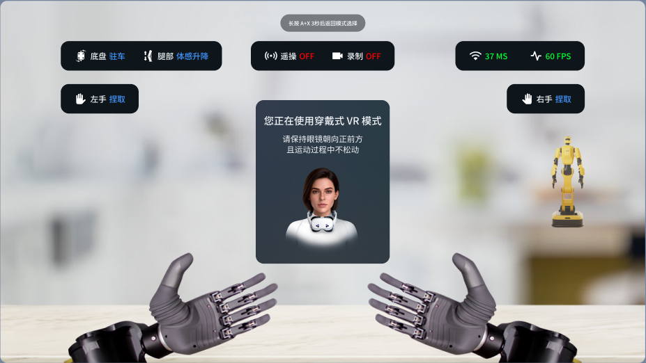
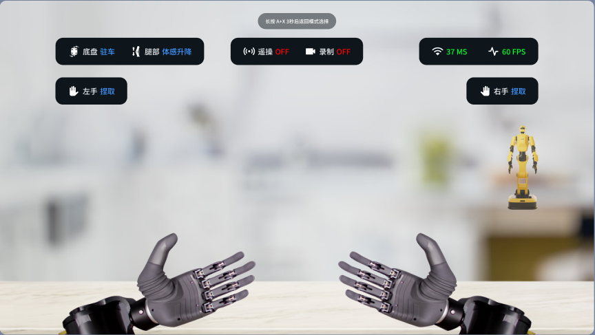
| Information Category | Mode/Status | Meaning | Description |
|---|---|---|---|
| Chassis/Leg Mode | Chassis | Robot chassis mode | Parking: The four chassis wheels are arranged in a cross pattern and locked in position to prevent unintended robot movement. |
| Differential: Wheels are unlocked and movement direction can be controlled via the joystick for robot mobility. | |||
| Leg | Mode for controlling leg movements via joystick/teleoperation | Motion-Sensing Lift/Lower: Leg lift height is controlled via teleoperation. The legs move only along the vertical axis without changing their tilt angle. Suitable for scenarios where the robot's leg height needs to be adjusted. | |
| Height Locked: The robot's leg joints are locked to maintain a fixed height. | |||
| Joystick Lift/Lower: Leg lift height is controlled via the left joystick (forward/backward). | |||
| Pose Synchronization: Leg lift/lower and forward/backward tilt are controlled via teleoperation. The legs change their tilt angle to adjust the robot's overall posture. | |||
| Teleoperation/Recording Status | Teleoperation | Indicates whether the robot is under teleoperation control | ON: Teleoperation is enabled. |
| OFF: Teleoperation is disabled. | |||
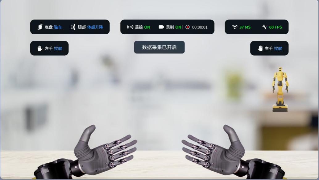
| Recording | Indicates whether data recording is in progress | ON: Data recording is active, and the voice prompt "Data recording started" is played. | |
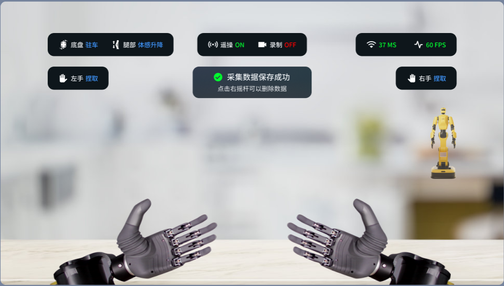
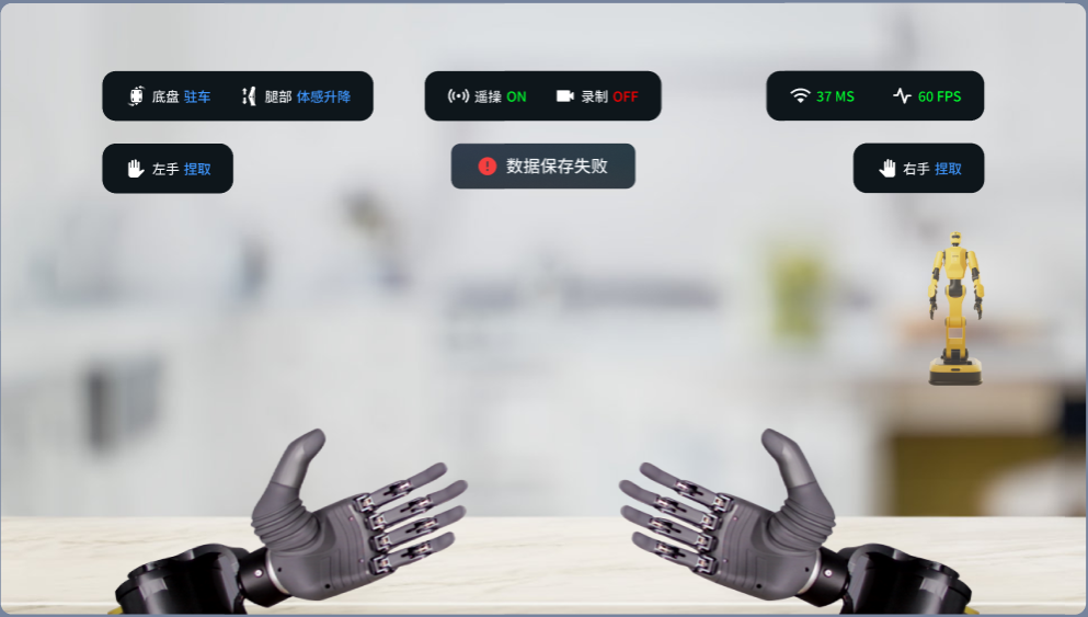
| OFF: Data recording has ended, and the voice prompt "Data saved successfully" or "Data save failed" is played. | |||
| Network Latency / Frame Rate | Network Latency | Real-time network latency (ms) | Latency < 250 ms: Normal latency. |
| 300 ms > Latency ≥ 250 ms: Relatively high latency. | |||
| Latency ≥ 300 ms: Excessively high latency. Can be resolved by checking network signal strength, closing unrelated applications on the personal computer, and terminating background processes on the robot's onboard system. | |||
| Frame Rate | Number of refreshes per second on the VR teleoperation desktop; reflects the smoothness of the VR desktop. | Higher frame rate values indicate smoother VR desktop performance. Low values may result in stuttering or motion blur. | |
| Left/Right Hand | Left Hand | Current grasping action of the left hand. | Includes preset gestures such as "Pinch," "Cup" and "Fist." User-defined actions are also supported. |
| Right Hand | Current grasping action of the right hand. | Includes preset gestures such as "Pinch," "Cup" and "Fist." User-defined actions are also supported. |
4.2.6 Starting Teleoperation
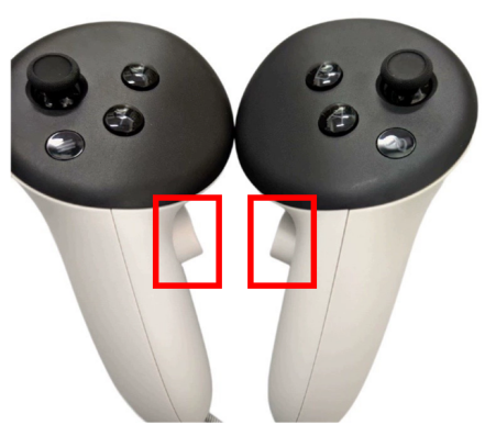
- Use the middle fingers of both hands to simultaneously press and hold the grip buttons on the left and right controllers. Once pressed, do not release them; releasing either grip button will exit teleoperation.
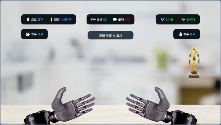
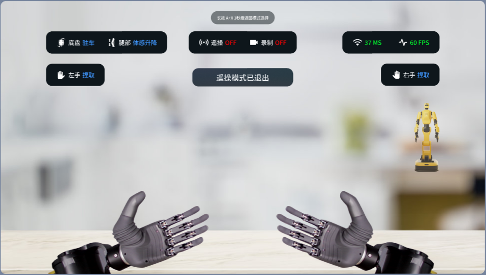
- After teleoperation starts, the teleoperation status on the VR interface will display ON, accompanied by the prompt "Teleoperation mode activated." Once teleoperation is activated, users cannot return to the mode selection interface by long‑pressing A + X for three seconds.
Note:
During controller operation, excessive downward wrist extension or movement of the controllers outside the visual tracking range of the VR headset may cause the controllers to become undetectable, resulting in the teleoperation status switching to OFF and interrupting data recording.
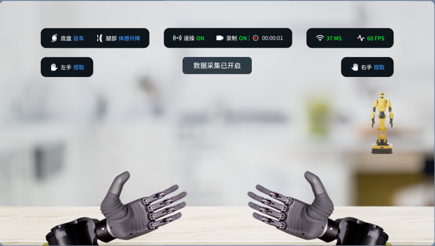
- Single‑click the left joystick to start data recording. The data recording status on the VR interface will display ON, and a pop‑up prompt "Data recording started" will appear.
- The robot will mirror the user's hand, arm, leg, and waist movements accordingly. Single‑click the B button to toggle the chassis mode, the Y button to toggle leg movements, the X button to toggle the left hand gesture, and the A button to toggle the right hand gesture.
4.2.6.1 Chassis Mode
The chassis mode defaults to Parking Mode. When the robot needs to be repositioned, switch from Parking Mode to Differential Mode, then use the right joystick to control forward/backward movement and the left joystick to control left/right rotation.
When performing actions such as crouching/standing up, forward/backward leaning, or left/right waist rotation, the robot's position must be fixed. Switch back to Parking Mode to prevent unintended robot movement.
When switching leg modes, the system will automatically switch the chassis mode to Parking Mode, eliminating the need for manual switching and ensuring stable robot positioning during leg operations.
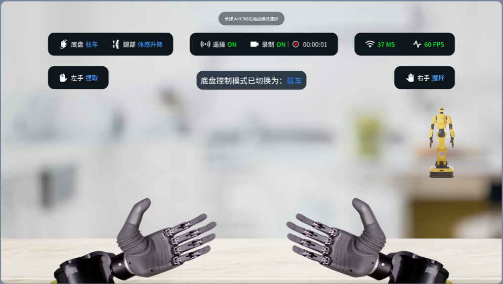
Press the B button to toggle the chassis mode. An on‑screen prompt will display: "Chassis control mode switched to: XXXX".
Note:
When entering teleoperation in Wearable VR Mode, the chassis mode is forcibly set to Parking Mode. In this state, the robot chassis cannot be moved via the joysticks, and the B button input for toggling the chassis mode is ignored.
4.2.6.2 Leg Movements
- When the robot needs to crouch or stand up, switch the leg mode to either Motion‑Sensing Lift/Lower or Joystick Lift/Lower. In Motion‑Sensing Lift/Lower, the robot follows the user's movements to stand up or crouch; in Joystick Lift/Lower, the left joystick is used to control leg lifting and lowering.
Note:
If the robot height has been lowered via Joystick Lift/Lower, switching the leg mode to Motion‑Sensing Lift/Lower and entering teleoperation will cause the robot to automatically return to the preset natural height. Ensure that the area around the robot is clear of obstacles in advance to avoid collisions.
- Each time the leg mode is switched, the chassis automatically switches to Parking Mode to prevent loss of control or falling during the transition. After completing the leg movements, if robot repositioning is required, manually switch the chassis to Differential Mode.
Note:
To switch leg modes, release the grip buttons with both middle fingers to exit teleoperation, single‑click the Y button to toggle the mode, and then press and hold the grip buttons again to re‑enter teleoperation.
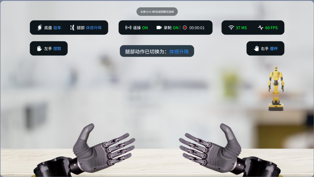
Press the Y button to toggle leg movements. An on‑screen prompt will display "Leg movements switched to: XXXX", accompanied by a voice announcement of the corresponding leg state name.
4.2.6.3 Left and Right Hand Control
Note:
To control the grasping of the left and right hands, press and hold the trigger buttons with both index fingers.
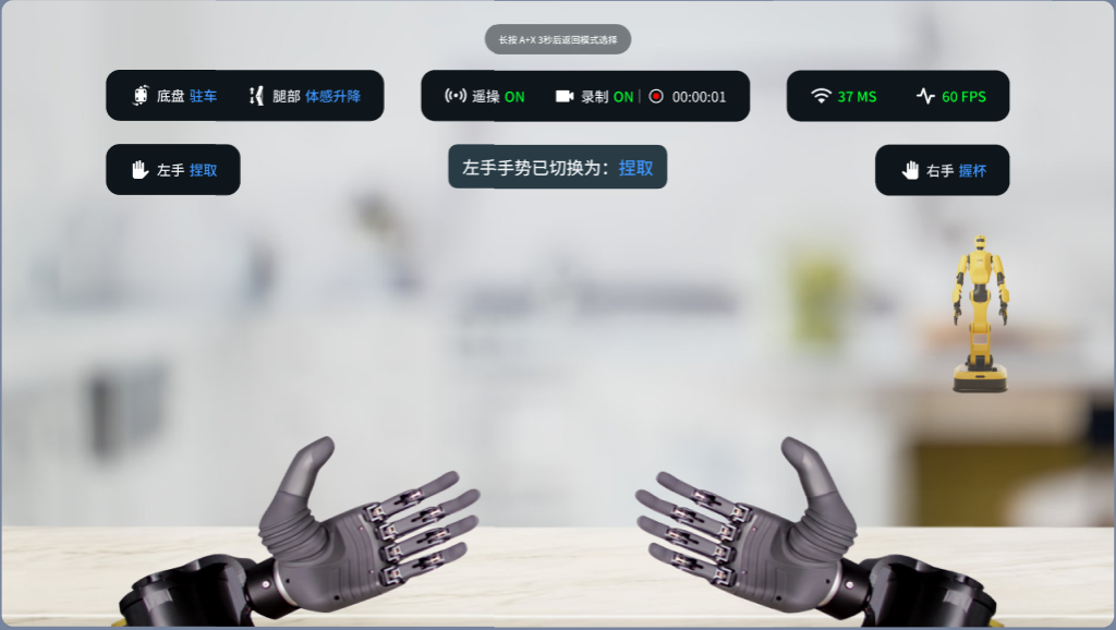
Press the A button to toggle the right hand gesture. An on‑screen prompt will display "Right hand gesture switched to: XX", accompanied by a voice announcement of the corresponding gesture name.
Press the X button to toggle the left hand gesture. An on‑screen prompt will display "Left hand gesture switched to: XX", accompanied by a voice announcement of the corresponding gesture name.
The complete list of gestures is provided below:
| Pinch | Cup | Fist | Thumbs | Heart | Rock | Pistol |
|---|---|---|---|---|---|---|
| Six | One | Salute | ok |
4.2.6.4 Error Clearing
During teleoperation, joint motor alarms may occur. Single‑click the Y button to clear the error, then adjust the robot's pose via teleoperation.
4.2.6.4.1 Self‑Collision Protection
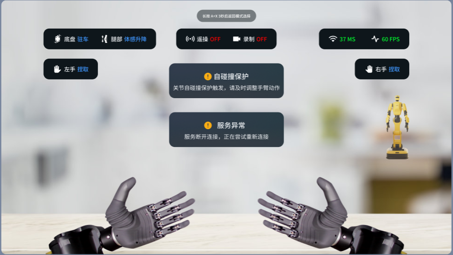
During teleoperation, if the robot's arm movements present a risk of joint self‑collision, the self‑collision protection mechanism is automatically triggered. An on‑screen prompt will display "Joint self‑collision protection activated. Please adjust your arm movements accordingly." A voice announcement will also be played: "Self‑collision protection. Move arms away from the body."
Once self‑collision protection is triggered, the robot will not follow the user's current movements. No manual error clearing is required. The user simply needs to adopt a pose that does not trigger collision protection; the robot will then slowly follow the user until full motion synchronization is restored.
4.2.6.4.2 Joint Motor Alarm
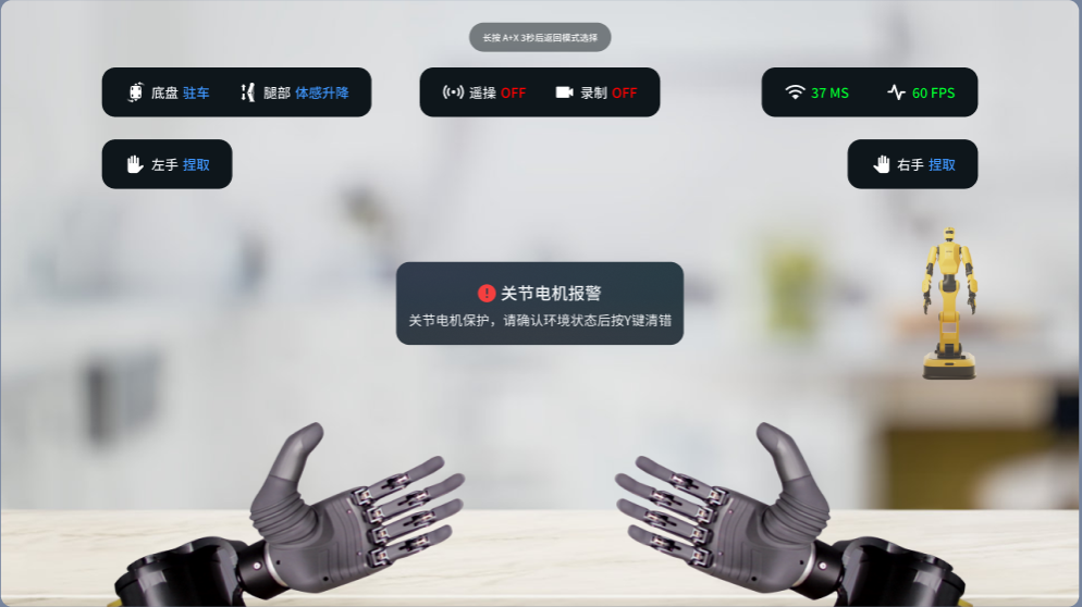
In high‑speed teleoperation scenarios (e.g., excessive motion amplitude or excessive speed), joint motors may experience overload or abnormal loads, triggering a joint motor alarm. A voice announcement will be played: "Joint motor protection. Press Y to clear the error." After confirming that the area around the robot is clear of obstructions, single‑click the Y button to clear the error, then adjust the robot's pose via teleoperation.
4.2.7 Data Recording
Note:
Data recording consumes a significant amount of system memory and computational resources. It is recommended to close unnecessary background processes on the VR desktop before recording to ensure a more stable recording experience.
Avoid excessively long recording sessions, as prolonged recordings may result in trailing frame loss.
4.2.7.1 Starting Data Recording
- Single‑click the left joystick to start data recording. The data recording status on the VR interface will display ON, with a pop‑up prompt
"Data recording started"and a voice announcement "Data recording started."
4.2.7.2 Stopping Recording
- Press the left joystick again to stop the current recording session. The data recording status on the VR interface will display OFF, with a pop‑up prompt
"Saving recorded data. Please wait..."and a progress bar displaying the saving percentage in real time.
Note: If teleoperation is exited during data recording, the recorded data for this session will be automatically saved to the corresponding folder.
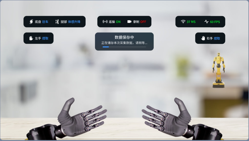
After recording stops, data will be written from memory to the hard drive. This process takes some time. Please wait patiently for the save to complete and refrain from performing other operations during the saving process to avoid interrupting the write operation.
4.2.7.3 Data Saving
- A pop‑up prompt will appear on the VR interface indicating
"Data saved successfully"or"Data save failed", accompanied by a voice announcement of the corresponding message.
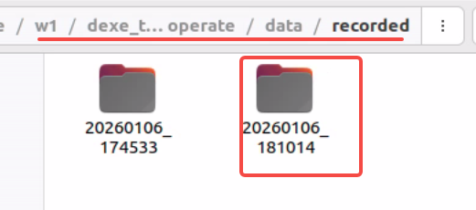
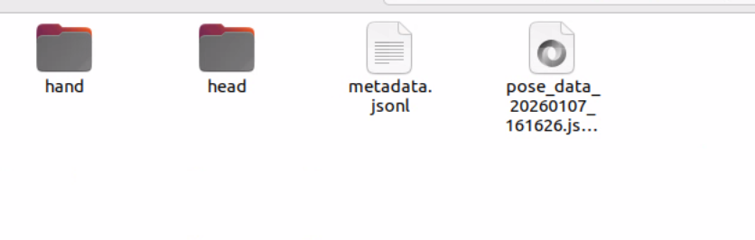
- Successfully saved recording data is stored in the following directory:
/home/dexforce/w1/dexe_teleoperate/data/recorded/20260113_192729(where20260113is the timestamp).
4.2.7.4 Deleting Recorded Data
Note: Data cannot be deleted during the recording process. You must stop recording before deletion.
- Single‑click the right joystick to delete the previously recorded data segment. A pop‑up prompt will appear on the VR interface asking
"Confirm data deletion?", accompanied by a voice announcement of the same message.
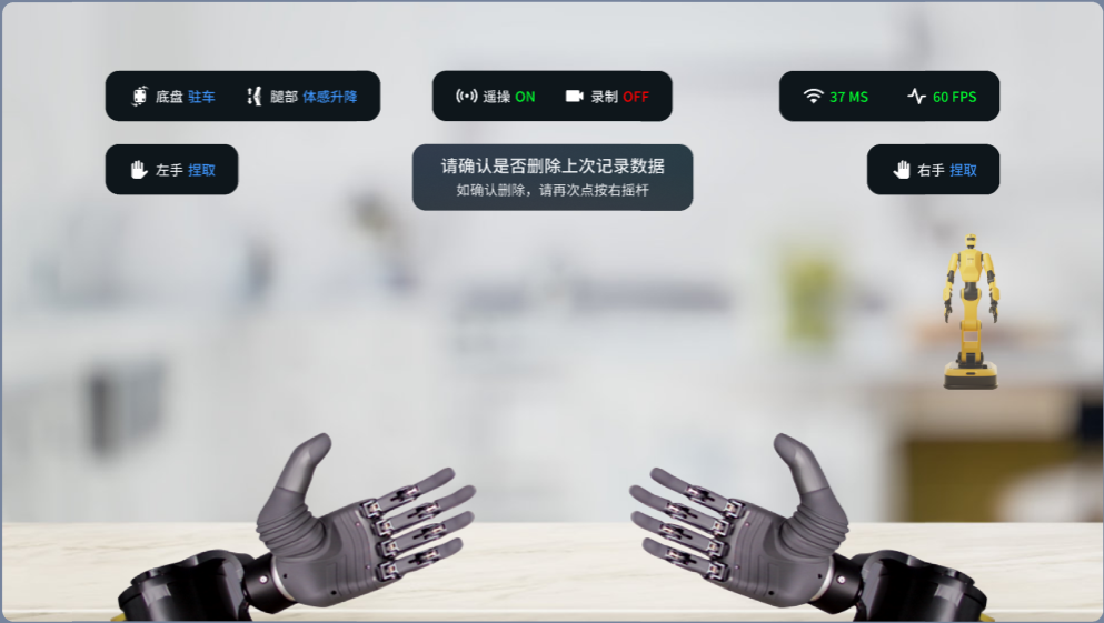
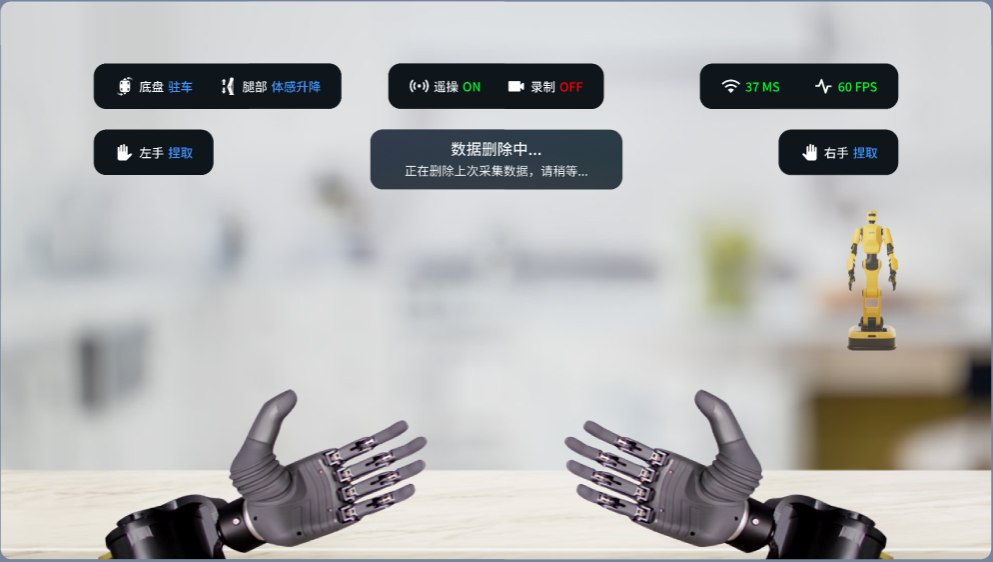
- Click the right joystick again to confirm deletion of the recorded data. The VR interface will display
"Deleting the last recorded data. Please wait..."During the process, a progress bar will show the deletion progress in real time. Upon successful deletion, a pop‑up prompt will appear on the VR interface:"Teleoperation data deleted", accompanied by a voice announcement of the same message. If the deletion fails, a voice announcement will play:"Data deletion failed."
4.2.8 Human-Robot Calibration
When entering Human-Robot Calibration mode, the teleoperation controller's ray pointer is used to select points on the slider. To return to the mode selection interface at any time, press and hold the X button on the left controller and the A button on the right controller simultaneously for 3 seconds.
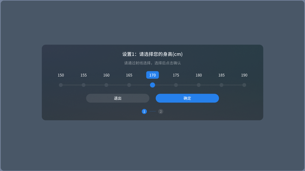
- Setting Height
Height is defined as the distance from the top of the head to the ground. The default height is 170 cm, with quick‑select options available for user adjustment. Once confirmed, the system records the selected value. The next time the user enters the Human‑Robot Calibration interface, this recorded value will be used as the new default.
To adjust, click the A button or the trigger button on the teleoperation controller to select different points on the slider. After making a selection, click the "Confirm" button using the trigger button.
- Setting Arm Length
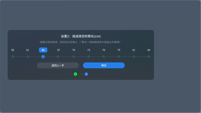
Arm length is defined as the distance from the acromion (shoulder peak) to the tip of the middle finger. The default arm length is 70 cm, with quick‑select options available for user adjustment. Once confirmed, the system records the selected value. The next time the user enters the Human‑Robot Calibration interface, this recorded value will be used as the new default.
To adjust, click the A button or the trigger button on the teleoperation controller to select different points on the slider. After making a selection, click the "Confirm" button using the trigger button.
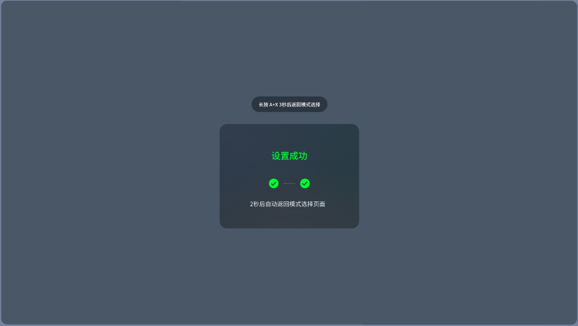
- Calibration Successful
The system displays the message "Setup successful" and automatically returns to the mode selection interface after 2 seconds, indicating that calibration is complete.
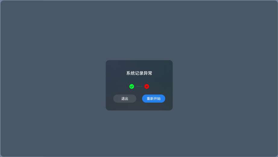
- Calibration Failed
The system displays a "System recording anomaly" prompt, indicating that calibration has failed. The user can click the "Restart" button to retry the calibration process, or click the "Exit" button to return to the mode selection interface.
4.2.9 Exiting Teleoperation
- Release the grip buttons with both middle fingers to exit teleoperation. The teleoperation status on the VR interface will display OFF, accompanied by the prompt
"Teleoperation mode exited."
Note: If data recording is still active when teleoperation is exited, the recorded data will be automatically saved.
- To re‑enter teleoperation, it is recommended to first long‑press the Meta button to reset the VR view, then press and hold the grip buttons with both middle fingers to re‑enter teleoperation.
4.2.10 Teleoperation Voice Interaction
| Type | Event | On‑Screen Prompt | Voice Announcement |
|---|---|---|---|
| Error Prompts | Self‑Collision Protection | Joint self‑collision protection activated. Please adjust your arm movements accordingly. | "Self‑collision protection. Move arms away from the body." |
| Joint Motor Alarm | Joint motor protection activated. Confirm environmental safety and press Y to clear the error. | "Joint motor protection. Press Y to clear the error." | |
| Chassis Not Enabled | Chassis is not enabled. Teleoperation movement is unavailable. | - | |
| Data Recording & Deletion | Data Recording Started | Data recording started. | "Data recording started." |
| Data Saving in Progress | Saving recorded data. Please wait... | - | |
| Data Saved Successfully | Data saved successfully. | "Data saved successfully." | |
| Data Save Failed | Data save failed. | "Data save failed." | |
| Data Deletion Confirmation | Confirm deletion of the last recorded data? Click the right joystick again to confirm. | "Please confirm data deletion." | |
| Data Deletion in Progress | Deleting the last recorded data. Please wait... | - | |
| Data Deletion Successful | Teleoperation data deleted. | "Teleoperation data deleted." | |
| Data Deletion Failed | Data deletion failed. | "Data deletion failed." | |
| Interaction Feedback | Gesture Switching | Left/Right hand gesture switched to: XX | "XX (gesture name)" |
| Leg Movement Switching | Leg movement switched to: XX | "XXXX (leg state name)" | |
| Chassis Mode Switching | Chassis control mode switched to: XX | - | |
| Entering Teleoperation | Teleoperation mode activated. | [Teleoperation activation sound effect] | |
| Exiting Teleoperation | Teleoperation mode exited. | [Teleoperation exit sound effect] | |
| Error Prompts | Unable to Enter Teleoperation in VR Mode | Unable to enter VR mode. Please check the backend service. | - |
| Backend Service Disconnection in VR Interface | Service abnormal. | "Service disconnected." |
4.2.11 Teleoperation Action Recording
To record custom actions, you can use teleoperation to capture a series of连贯 motion poses and generate an action file. This file can then be used in the W1 Control Interface to command the robot to automatically replay the entire set of recorded actions with a single click.
4.2.11.1 Recording Demo via Commands
Control the robot and perform the desired actions for recording (Refer to the Teleoperation Instructions section). The recorded data will be automatically saved as a .json file.
① Enter the teleoperation interface. While controlling the hands with both hands, press the joystick button on the left controller to trigger recording. Press it again to stop recording.
If you are recording a check‑in action such as "Heart Gesture," to ensure smooth transitions with other actions, it is recommended to start with both arms naturally hanging down, then proceed to perform the single‑hand or double‑hand heart gesture, and finally return both arms to the natural hanging position as the ending pose.
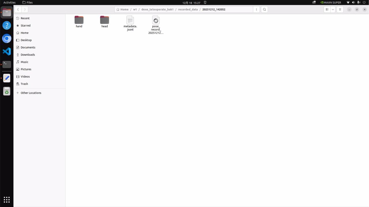
② After you release the grip buttons with both middle fingers and exit teleoperation mode, the recorded file (e.g., pose_record_xxxx.json) will be automatically saved to the following directory: w1/dexe_teleoprate/recorded_data/[timestamp]/
4.2.11.2 Replacing the Action File
Replace the old action file with the newly recorded action file.
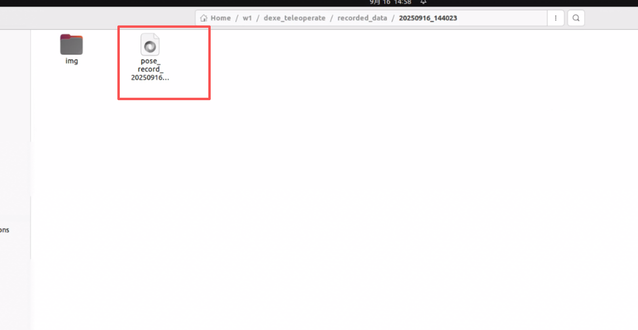
① In the directory w1/dexe_teleoprate/recorded_data/[timestamp]/, locate the complete action file corresponding to your recording. The following path contains the newly recorded full action file:
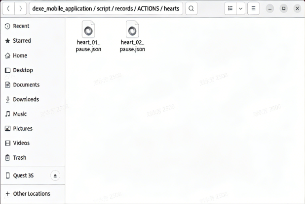
② Place this file into the following directory: w1/dexe_mobile_application/script/records/ACTIONS/[action_name]/ where [action_name] is the English name of the newly recorded action (e.g., hearts for Heart Gesture, pinch for Pinch, cup for Cup Grasp, fist for Fist, like for Thumbs Up).
③ Delete the original file in the w1/dexe_mobile_application/script/records/ACTIONS/[action_name]/ directory, then rename the newly recorded file. There are no restrictions on the filename itself; it only needs to be distinguishable.
Note: If the old file is not deleted, the system may load a file other than your newly recorded action due to the presence of multiple files in the directory.
4.2.11.3 Testing the Demo
At this point, when running the preset actions and clicking on the Heart Gesture, the corresponding playback will be the newly recorded heart gesture action.
4.2.11.4 Replaying the Demo
To replay a preset action or a newly recorded demo, execute the following command in the PC1 terminal:
cd w1
source install/setup.bash
cd dexe_mobile_application/script
python replay.py /path/to/action.json #action.json是指预设动作和新录制demo的存储路径,比如records/ACTIONS/hearts/hearts_01.json
4.2.11.5 Returning the Robot to the Initial Pose
After executing a preset action or a newly recorded demo, if you wish to return the robot to its initial pose (i.e., the first frame of the action), execute the following command in the PC1 terminal:
cd w1
source install/setup.bash
cd dexe_mobile_application/script
python slowly_move_to.py /path/to/action.json#action.json是指预设动作和新录制demo的存储路径,比如records/ACTIONS/hearts/hearts_01.json
4.3 W1 Control Interface
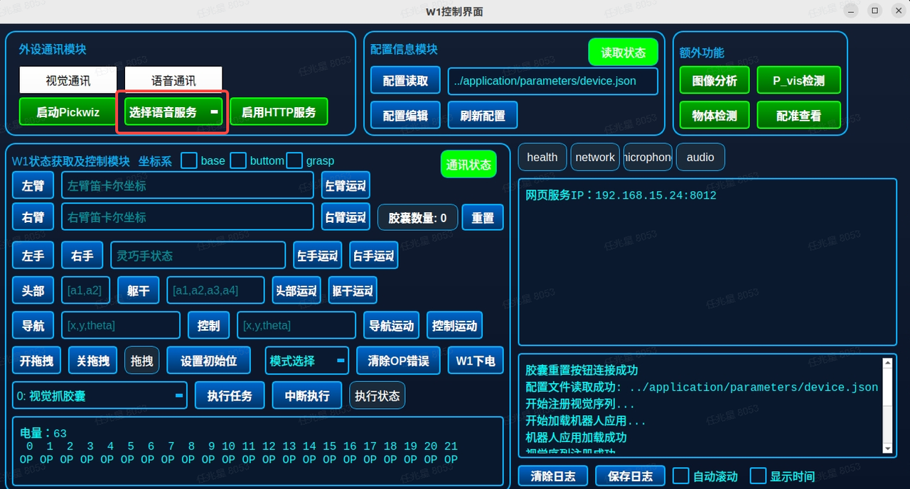
The W1 Control Interface provides comprehensive functionalities including robot status monitoring, manual teaching in joint/Cartesian space, task trajectory recording and playback, and one‑click execution of preset tasks (e.g., coffee brewing). It serves as a centralized and visualized master control platform for operators, functioning as the "command center" that coordinates and schedules the underlying control system, vision modules, and voice modules. It is key to integrating individual subsystems into a complete application and is essential for advanced task control, motion debugging, and system supervision.
The W1 Control Interface automatically detects the connection status and establishes communication links accordingly.
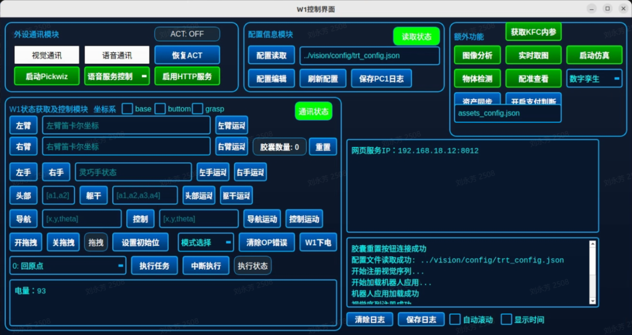
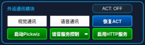
4.3.1 Peripheral Communication Module
| Name | Description |
|---|---|
| Vision Communication | When the "Vision Communication" indicator is illuminated, it signifies that TCP communication with PickWiz has been successfully established. |
| Launch PickWiz | Opens the launcher interface and starts PickWiz. The "Stop PickWiz" button only stops the terminal log display; to fully close PickWiz, manual termination is required. |
| Voice Communication | When the "Voice Communication" indicator is illuminated, it indicates that communication with the voice server has been established. Once the microphone and speakers are properly installed and selected, voice-triggered interactions can be performed via the microphone. |
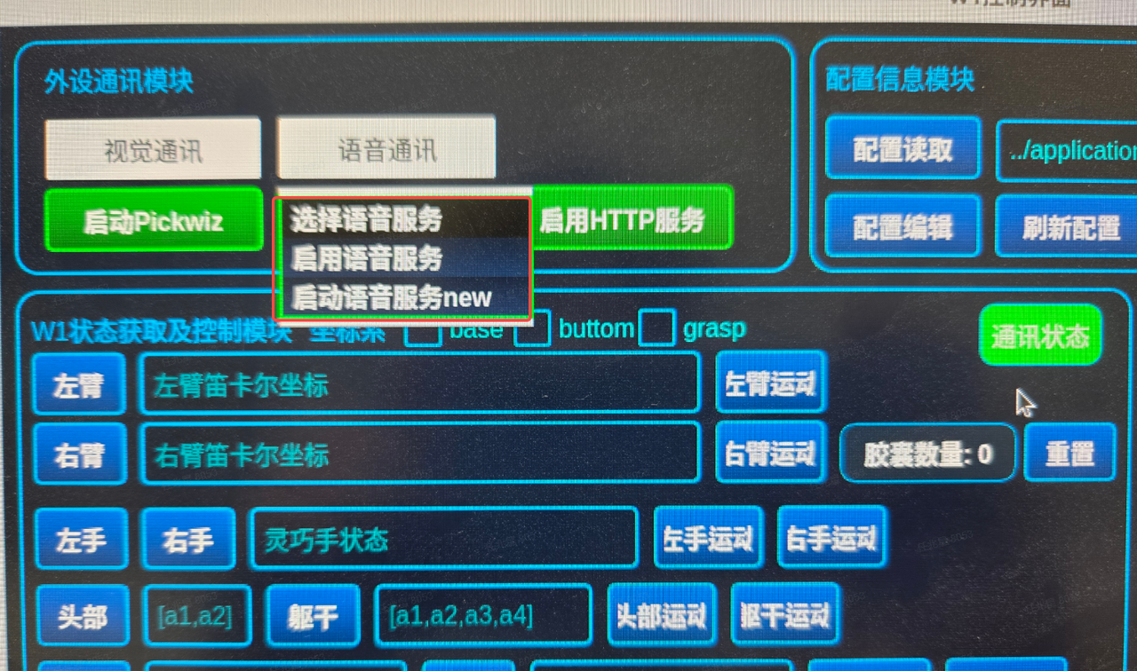
| Voice Service Control | 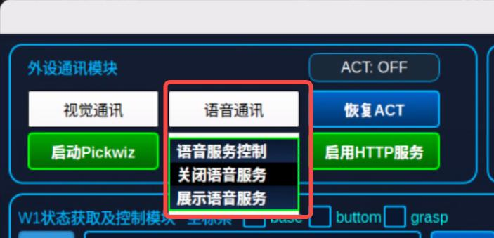 -Voice Service Control: This function must be used in conjunction with the Voice Communication button to connect to the voice server. Once connected, continuous communication is established, enabling normal dialogue and task issuance. -Voice Service Control: This function must be used in conjunction with the Voice Communication button to connect to the voice server. Once connected, continuous communication is established, enabling normal dialogue and task issuance.-Close Voice Service: Hides the voice UI interface. -Show Voice Service: Displays the voice UI interface. User speech is given the highest priority and will interrupt any ongoing voice service. |
| Enable HTTP Service | Clicking "Enable HTTP Service" allows users to access the application via a web browser on a PC or tablet, enabling remote robot control through the tablet-based coffee ordering interface. |
| Restore ACT | Clicking "Restore ACT" triggers the robot to proactively perform greetings and handshakes. |
| ACT: OFF | Clicking "ACT: OFF" stops the robot's greeting and handshake actions and automatically returns it to the preset default position. |
4.3.2 Configuration Information Module
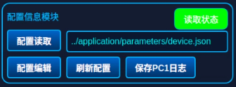
| Load Configuration | Loads a new configuration. Currently, configurations are loaded automatically; loading from a new path is not supported. (The software automatically reads the configuration; this button is currently non-functional.)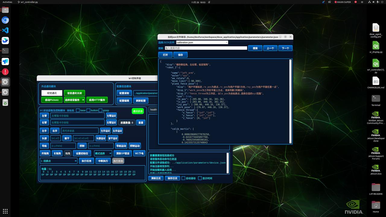 |
|---|---|
| Edit Configuration | Opens the configuration editing UI. After modifying parameters, users must click Save to update the configuration.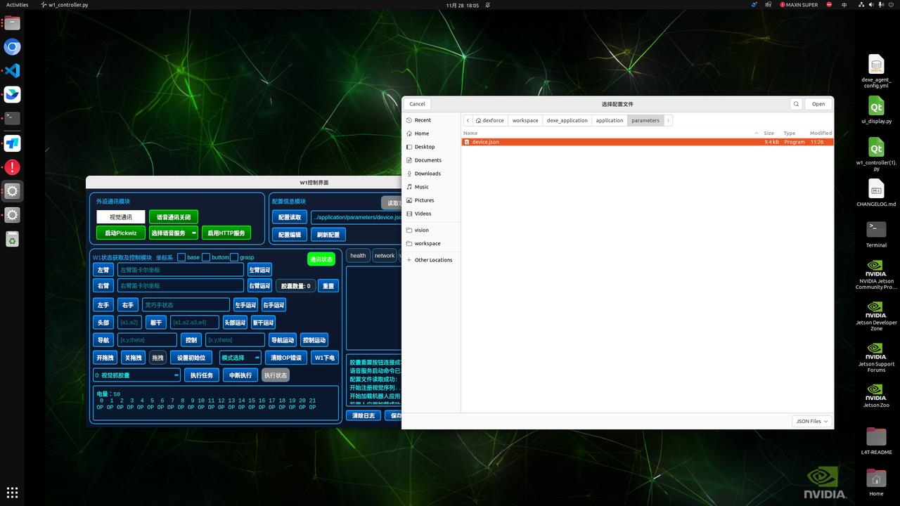 To modify the To modify the w1_manager configuration in dexe_application/application/parameters/parameter.json, pre‑store the required w1_manager controller information under the profiles parameter. When switching end‑effectors, simply modify the active_profile parameter.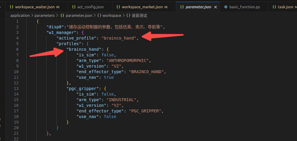 |
| Refresh Configuration | After the configuration is saved, click this button for the changes to take effect in the current session. Otherwise, the software must be restarted for the changes to apply. |
| Save PC1 Logs | Clicking this button triggers a confirmation pop‑up. After clicking Confirm, the system starts saving logs in the background. The entire ~/log folder on PC1 will be saved to ~/log/log_pc1 on PC2.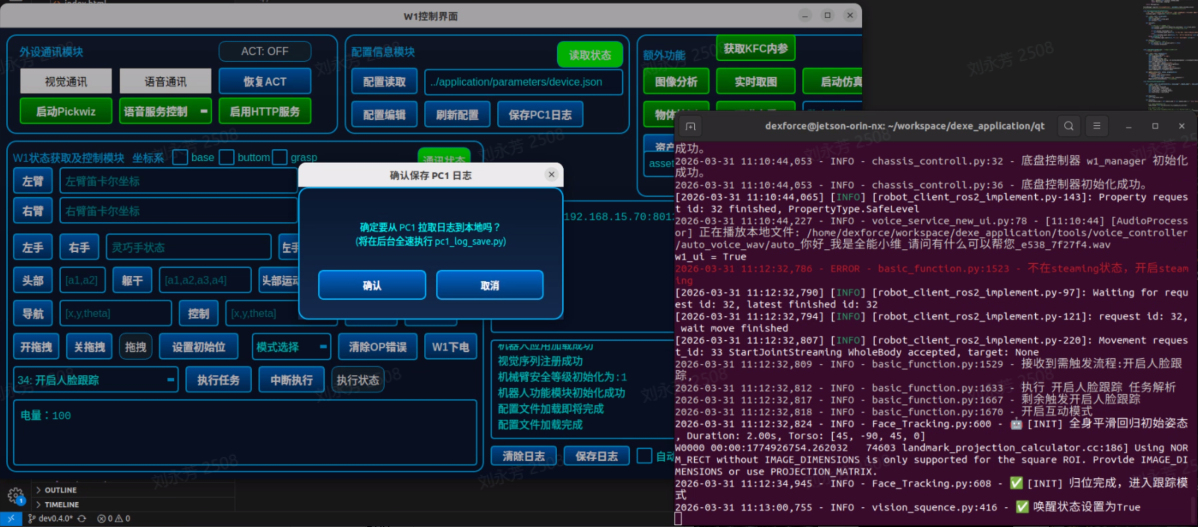 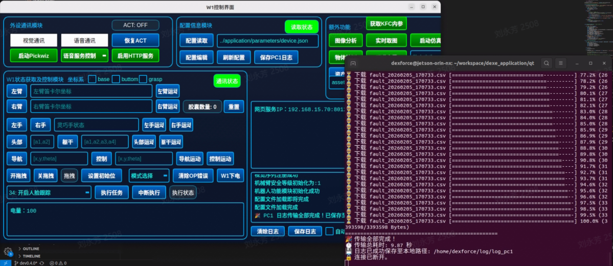 |
4.3.3 Additional Functions
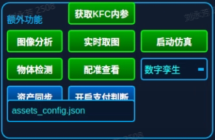
| Image Analysis | Used to determine whether the color in the current ROI region matches the preset color. If not, the corresponding logic is triggered.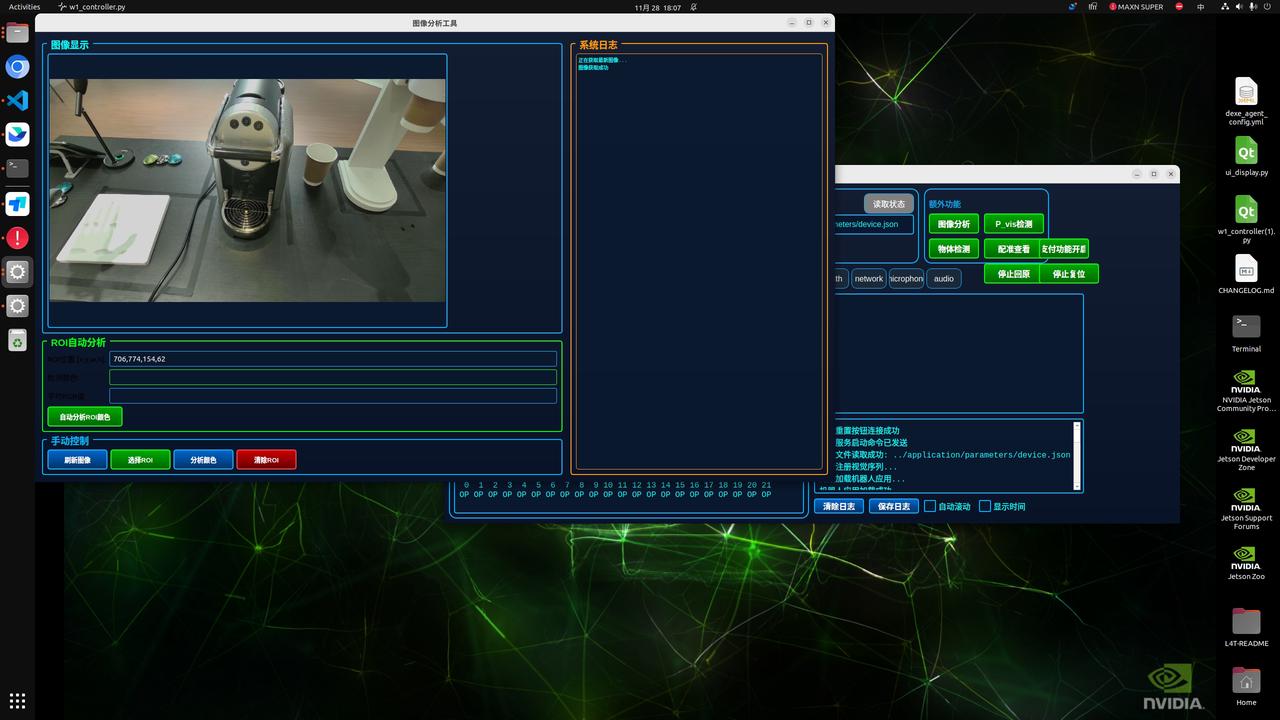 |
|---|---|
| Object Detection | Based on the YOLO detection model, supports full‑category detection for the coffee workstation, with ROI‑based region selection for detection. Specific areas can be defined within the image to view detection results.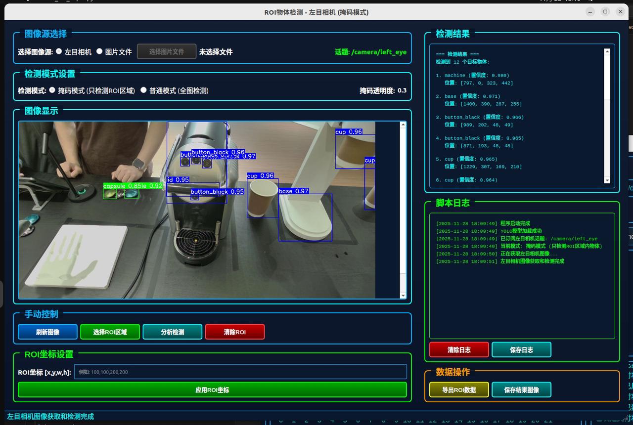 |
| Get KFC Intrinsics | Clicking this button prompts a confirmation dialog. Upon confirmation, the KFC intrinsic parameters are saved to the following path: /home/dexforce/workspace/dexe_application/vision/config/KFC-ROS.0.yaml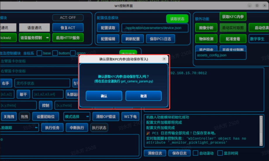 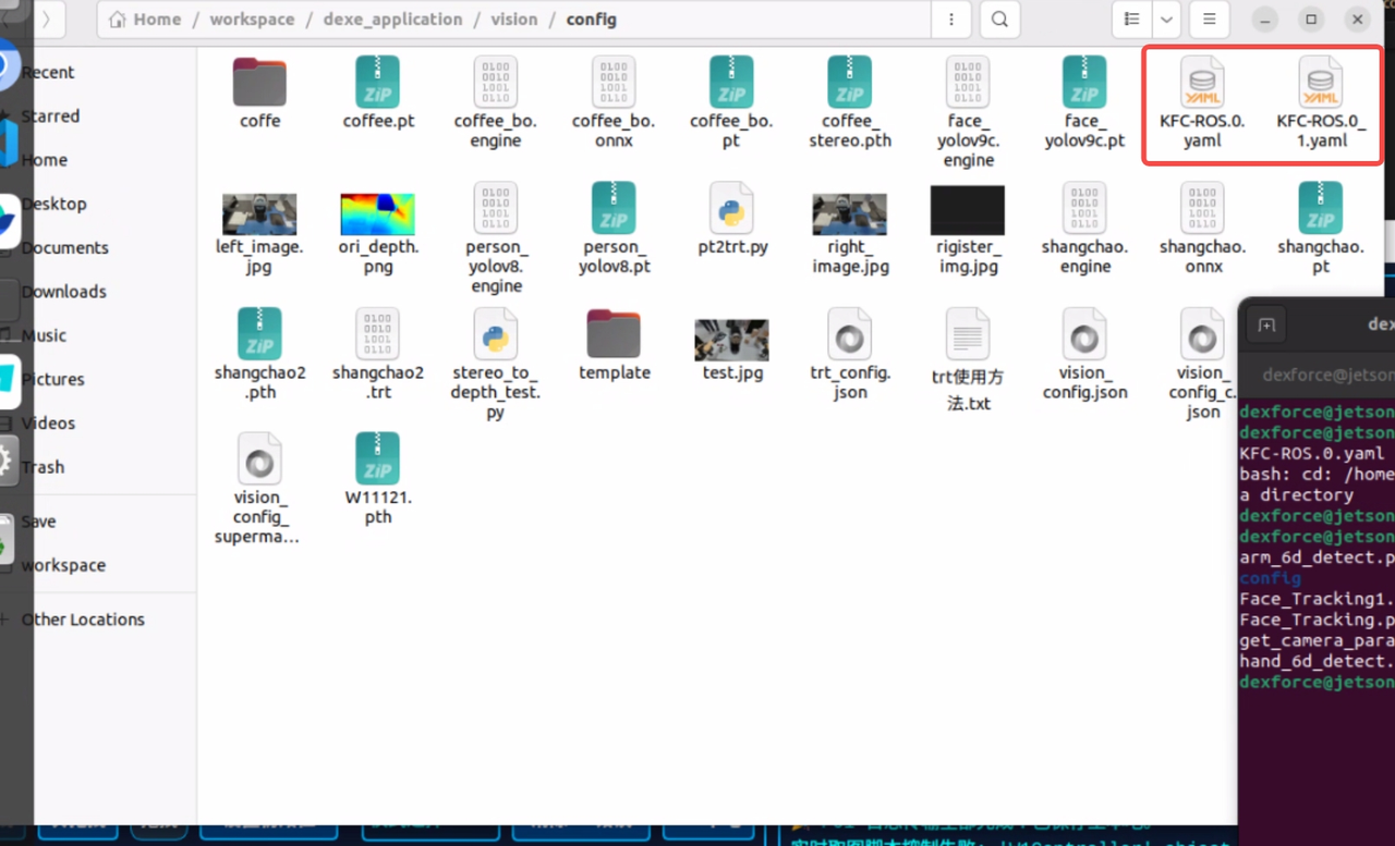 |
| Real‑Time Image Capture | Clicking this opens a real‑time left‑right stereo image window. Clicking the close capture button will turn the display black, and the window will automatically exit after approximately 3 to 5 seconds.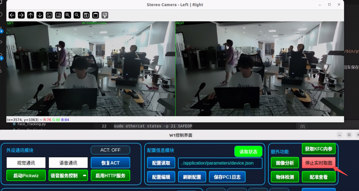 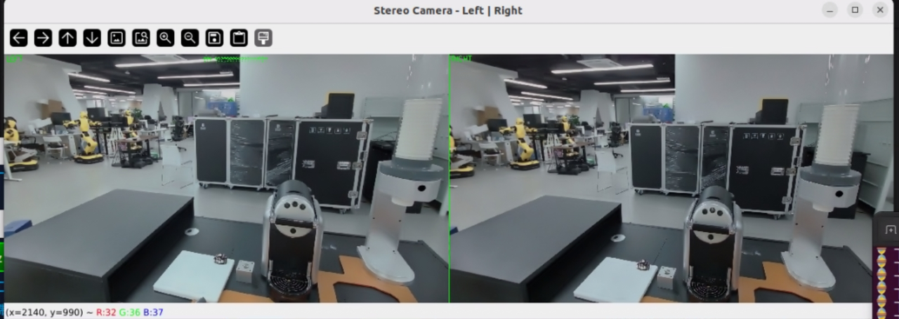 |
| Calibration View | A function for viewing point cloud registration results. |
| Asset Synchronization | Automatically manages the asset files required for robot operation, ensuring consistency between local assets and cloud configurations. Clicking the "Asset Synchronization" button triggers the system to read the configuration file at /home/dexforce/workspace/dexe_application/tools/asset_manager/assets_config.json, checks the integrity of local assets, and downloads any missing files from the cloud. |
| Enable Payment | Triggers the payment function. |
| Launch Simulation | Used to simulate robot motion and task execution in a virtual environment, with support for two modes:
|
4.3.4 W1 Status Acquisition and Control Module
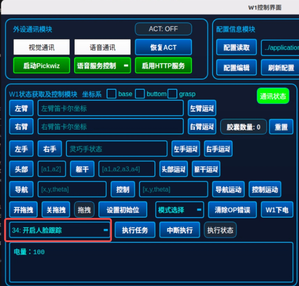
| Coordinate Frames | Reference coordinate systems used for positioning and describing component positions/orientations in robot motion control. -Base: The robot's "global reference frame," typically fixed to the robot's base or mounting surface (serving as the "origin reference" for the entire robot system). -Bottom: A local coordinate frame near the robot base (closer to the robot body than the base frame). -Grasp: The "tool frame" attached to the robot's end-effector (dexterous hand), with its origin typically at the center or contact point of the gripper. |
|---|---|
| Left Arm / Right Arm | Retrieves the current Cartesian pose of the left/right arm. Returns [x, y, z, a, b, c]. Joint coordinates can be viewed in the terminal log. |
| Left Hand / Right Hand | Retrieves the current pose of the left/right dexterous hand. A total of six control values are provided: the first two correspond to the thumb, and the remaining four correspond to the index finger through the little finger. Each control value ranges from [0, 100], where 0 indicates fully open and 100 indicates fully closed. |
| Head / Torso | Retrieves the current pose of the head and torso. The head has two control values: [left/right rotation, up/down tilt]. The torso has four control values: [three motors from bottom to top, and a fourth for horizontal rotation]. |
| Six Motion Buttons (Left Arm, Right Arm, Left Hand, Right Hand, Head, Torso) | Clicking a button moves the corresponding part to the position defined by the current control values. |
| Navigation / Control | Currently unavailable. |
| Enable Drag | Opens the force limits on the left and right arms. After clicking, the "Drag" indicator turns green, allowing manual dragging of the left and right arms. |
| Disable Drag | Restores the force limits on the left and right arms. When robot motion stops and the button is clicked, the "Drag" indicator turns off. |
| Set Initial Pose | The core function is to define the initial arm configuration, which is referenced for motion planning in subsequent coordinate movements. When "Return to Home" is used in the configuration, the robot returns to this position. |
| Mode Selection | Switches among three W1 control modes: Current Mode, Automatic Mode, and Teleoperation Mode. |
| Clear OP Error | When the robot fails to move and the terminal log displays "Streaming command send failed," an OP error has occurred and is pending clearance. Clicking this button clears the error and restores normal operation. |
| W1 Power Off | After clicking, a confirmation prompt will appear asking whether to shut down PC1 or PC2. |
| Execute Task | Selects a pre‑made task. Only one task can be selected at a time. Face Tracking: After clicking, W1 provides the following functions: face tracking, wave back to user's greeting, and voice interactions triggered by user phrases such as "Awesome," "Hello," "Who are you," and "Any recommendations." W1 will respond with corresponding actions and voice replies. |
| Interrupt Execution | During task execution, clicking this button terminates the ongoing task. |
| Execution Status | Displays green when a task is running, and gray after the task is completed. |
| Capsule Count | Applicable to capsule coffee barista scenarios. |
| Enable Payment | After clicking, order detection is activated. When disabled, coffee brewing can be triggered directly via the tablet ordering interface or voice commands. |
Note:
Please note that all motions in this section are executed by modifying numerical values. Exercise extreme caution when making modifications before initiating any motion.
Be aware that there is no collision detection between the left and right arms. Incorrect motion inputs may cause the left arm to collide with the right arm.
4.3.5 Log Display Area
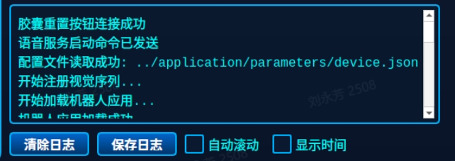
| Name | Description |
|---|---|
| Clear Logs | Clears all logs currently displayed on the interface. The log storage files are not cleared. |
| Save Logs | Saves all logs currently displayed on the interface. |
| Auto Scroll | Automatically scrolls to bring the latest log entries into the visible area. |
| Show Timestamps | Displays the timestamp for each log entry. |
4.3.6 Voice Module
This module integrates Automatic Speech Recognition (ASR) and Text‑to‑Speech (TTS) services, enabling the robot to listen to and understand user voice commands (e.g., "Make a cup of coffee") and provide feedback and status notifications via speech. It enables natural human‑robot interaction, allowing users to trigger complex task workflows through the most intuitive voice commands, thereby enhancing operational convenience and user experience, and equipping the robot with both "ears" and "a mouth."
Upon startup, the microphone and speaker devices are automatically connected. Open the Voice Service in the W1 Control Interface.
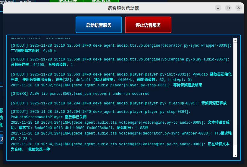
Then, interact with the robot using voice commands such as "Xiao Wei," "Hello, Xiao Wei," "Boss Wei," "Wei Wei," "Xiao Wei! Xiao Wei!" (all tones and variations are supported) to verify that the voice module has started up correctly.
4.4 Secondary Development Interface
Developers can conveniently access robot status, send control commands, and implement complex task programming and integration through standard ROS 2 communication mechanisms, including Topics, Services, and Actions.
Topic: A subscription‑based communication mechanism. Subscribers register for a specific topic, and publishers send messages to all registered subscribers based on the subscription list. This mechanism is primarily used for medium‑to‑high frequency or continuous data exchange.
Service: A request‑reply communication mechanism. Data retrieval or operations are performed via service requests. It is suitable for low‑frequency interactions or mode‑switching operations.
Action: A persistent, stateful communication mechanism designed for long‑running tasks. It supports real‑time status feedback and task cancellation during execution, making it ideal for complex motion control and task execution.
4.4.1 Common Topics
The following table lists several commonly used topics in the secondary development process, which are used for acquiring images, robot status, and robot control.
| Type | Topic Name | Topic Content | Usage Method |
|---|---|---|---|
| Camera Topics | Original Images:/camera/left_eye/camera/right_eye | 1920×1080 resolution, 5 Hz | Subscribe directly to obtain images. |
Resized Images:/camera/left_eye_resize/camera/right_eye_resize | 960×540 resolution, 30 Hz | ||
Compressed Image:/camera/kfc_compressed | Combined compressed image at 3840×1080; decoded to 1920×1080 resolution, 30 Hz | Requires decoding of the topic image before use. A decoding example file is provided below. The callback method in the code can be used for decoding.Stereo_Receiver.py | |
| Robot Joint Information Topics | Real Robot Joint Information:/feedback/jointSimulated Robot Joint Information: /feedback/joint_sim | header: Standard message headername: Joint orderposition: Joint angle (radians)velocity: Joint velocity (percentage)effort: Joint effort | Subscribe directly to obtain joint status. |
Left Hand Information: /feedback/hand/leftRight Hand Information: /feedback/hand/right | header: Standard message headername: hand joint orderposition: Joint angle (radians)velocity: Joint velocity (percentage)currentforcestate | ||
| Robot Joint Control Interface | /control/joint_position:/control/joint_position | 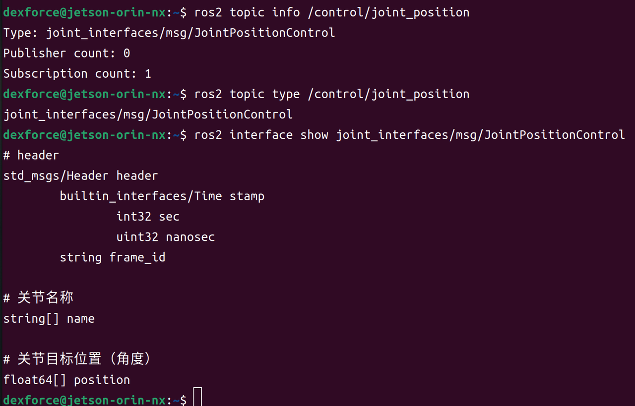 Joint Names (for control): Joint Names (for control):name:
| The following command can be executed directly in the terminal to test the topic interface. # Take the control of head joints as an example |
Full‑Body Joint Control with Velocity Limits:/control/joint | 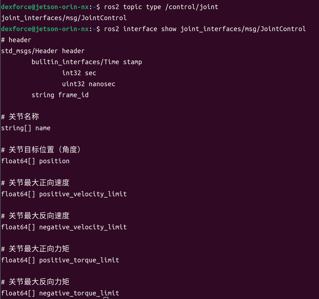
| The following command can be executed directly in the terminal to test the topic interface. # Take the control of head joints as an example | |
Left Hand Control Topic: /control/hand/leftRight Hand Control Topic: /control/hand/right | 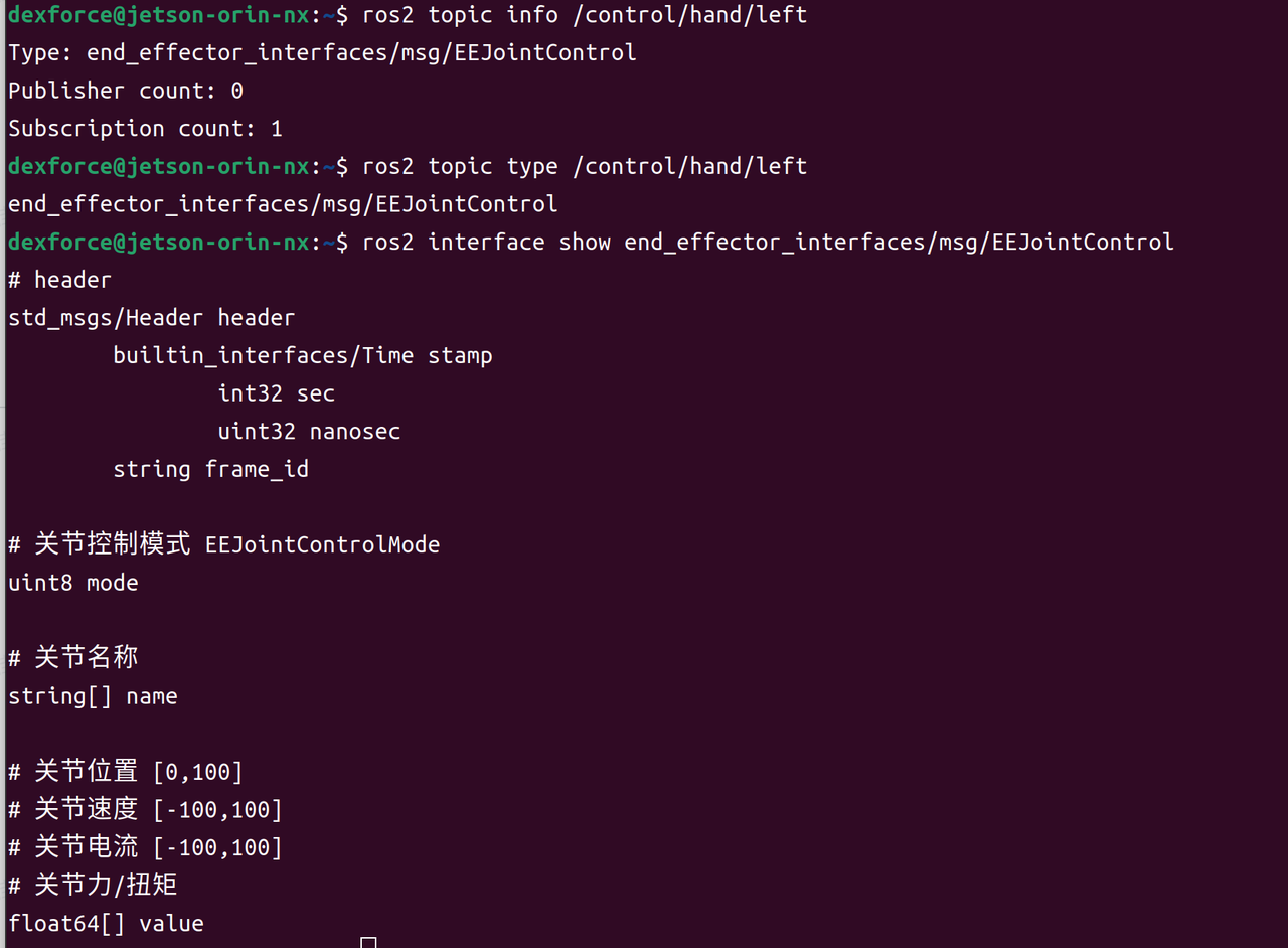 Joint Names (for control) Joint Names (for control)name:
| The following command can be executed directly in the terminal to test the topic interface. # Mode 0: Position Control, value range [0, 100]. 0 = fully open, 100 = fully closed # Mode 1: Velocity Control, value range [-100, 100]. Positive values = closing motion, negative values = opening motion |
For more information on other interfaces: Secondary Development Interface Specification V0.3.2
4.4.2 Interface Usage Guide
4.4.2.1 Upper Body Motion Control Interface
The dexe_robot_client package is pre-installed on every W1 Pro robot. Before use, instantiate the client class.
Core interface example files are provided below. Individual motion interfaces can be tested by running the corresponding Python code from these files.
| No. | Function | Parameters | Return / Effect | Interface Singleton File |
|---|---|---|---|---|
| 1 | get_current_qpos Get current joint positions (joint space) | name (str, optional): Specifies the component name. Available values: "full_body", "torso", "head", "left_arm", "right_arm", "left_arm_ee", "right_arm_ee". Default: "full_body". | Returns tuple[bool, np.ndarray]: Success flag + current joint position array. | example_get_current_qpos.py |
| 2 | get_current_pose Get current end‑effector pose (Cartesian space) | name (str): Arm name, "left_arm" or "right_arm".is_local (bool, optional): Whether the pose is relative to the arm's base frame. Default: True. | Returns tuple[bool, list]: Success flag + pose list [x_mm, y_mm, z_mm, roll_deg, pitch_deg, yaw_deg] | example_get_current_pose.py |
| 3 | move_joint_full_body Full‑body joint‑space motion | waypoints_dict (dict): Dictionary of target joint positions for each component. Supports multiple waypoints. speed_ratio (float, optional): Speed scaling factor. Default: 1.0. | Returns bool: Execution success status. Observe whether the robot moves as expected. | example_move_joint_full_body.py |
| 4 | move_linear_full_body Full‑body linear motion (Cartesian space) | waypoints_dict (dict): Dictionary of target poses for each component. Supports multiple waypoints. speed_ratio (float, optional): Speed scaling factor.<br />Default: 1.0. is_local (bool, optional): Whether poses are relative to the arm's base frame. Default: True. | Returns bool: Execution success status. Observe whether the robot moves as expected. | example_move_linear_full_body.py |
| 5 | set_ee_qpos Set end‑effector opening/closing | name (str): End‑effector name (e.g., "left_arm_ee").<br />qpos (np.ndarray): Target position, range 0–100. | Returns bool: Execution success status.Observe whether the hand moves as expected. | example_set_ee_qpos.py |
| 6 | stop_move Stop motion | timeout_sec (float, optional): Timeout duration for the stop command. Default: 3.0 seconds. | Returns bool: Stop success status. | example_stop_move.py |
| 7 | set_tcp Set the tool center point (TCP) relative to the flange | name (str): Arm name, "left_arm" or "right_arm".<br />xpos (np.ndarray): Target TCP pose transformation matrix, shape (4, 4). | Returns bool: Success status of the operation. | In the interface singleton file of 4.move_linear_full_body: |
4.4.2.2 2D Vision Interface
Currently, all 2D vision-related functionalities are implemented within the Function class located in: /home/workspace/dexe_application/application/basic_function.py
| Category | Function | Parameters | Return |
|---|---|---|---|
| Traditional 2D Algorithm | analyze_roi_color_simple Determine the color of a specific ROI region in an image. | roi_coords: ROI coordinates [x, y, w, h]camera_num: Number of images to capture image (optional): Pre‑captured image | color_name: Identified color name avg_r: Mean R value avg_g: Mean G value avg_b: Mean B value image_with_roi: Image with ROI overlay |
_detect_color_type_hsv利用HSV设置颜色 | r: Red channel value g: Green channel value b: Blue channel value | 字符串格式的颜色名称 | |
| Model‑Based Detection | analyze_roi_yoloPerform object detection in a specific ROI region using a YOLO model. | roi_coords: ROI coordinates [x, y, w, h]camera_num: Number of images to capture class_name: Target class for detection conf_threshold: Confidence threshold model_path: Path to the YOLO model image (optional): Pre‑captured imagepicture_name: Image save filename picture_save: Save configuration roi_save: Whether to save ROI roi_name: ROI region name |
|
_preload_yolo_models | 无参数 | This function takes no parameters and returns no value. When invoked, it preloads all models specified in parameter.json into memory for subsequent inference tasks. | |
_save_detection_image |
| This function has no return value. Its behavior is as follows:
|
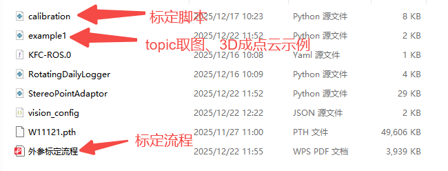
4.4.2.3 Interfaces for 3D Point Cloud Generation, Topic-Based Image Acquisition, and Extrinsic Calibration
(Please download this file at:https://docs.dexforce.com/en/Humanoid/W1Usermanual/V0.4.0/bblak9g2/)
4.4.2.4 Voice Interface
4.4.2.4.1 Core Interfaces
The voice functionality package is located at /home/dexforce/workspace/dexe_application/tools. Import it using the following command:
Core Interface Description
| Function | Parameter | Description |
|---|---|---|
chatStrByStr | String | Returns a model‑generated response string based on the user‑supplied input string. |
push_task_res | String | Adds the utterance to the playback queue. |
play_text | String | Interrupts the current utterance and plays the specified string immediately. |
_execute_command | String,String | Processes the user's utterance in conjunction with the task module and performs the corresponding action. |
recorder_task | None | Continuously detects and records audio, converting it into the corresponding text string. |
4.4.2.4.2 Usage Guide
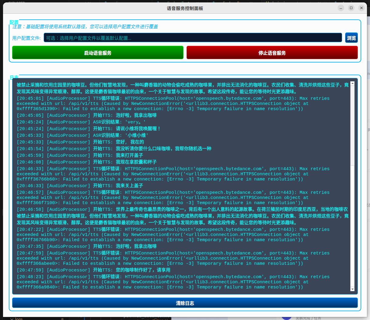
Users can select custom configuration text, which can be switched freely before starting the service. If left unspecified, the default voice configuration text is used. The wake‑up status and each TTS and ASR text output are displayed on the UI browser page for convenient voice monitoring.
Click "Start Voice Service (New)" to launch the voice module UI. Upon startup, the configuration defaults to reading two JSON files: device.json and voice.json.
device.json: Contains advanced settings that generally do not require modification. Adjustable parameters include audio input sensitivity, interval timing, ASR and TTS configurations, and the voice chat character.voice.json: Contains a set of similarity‑matched phrases. Users are free to modify this file or create a custom configuration file, and select it via the user configuration panel before starting the voice service.