Quick Start
3.1 Unpacking and Repacking
3.1.1 Unpacking Inspection
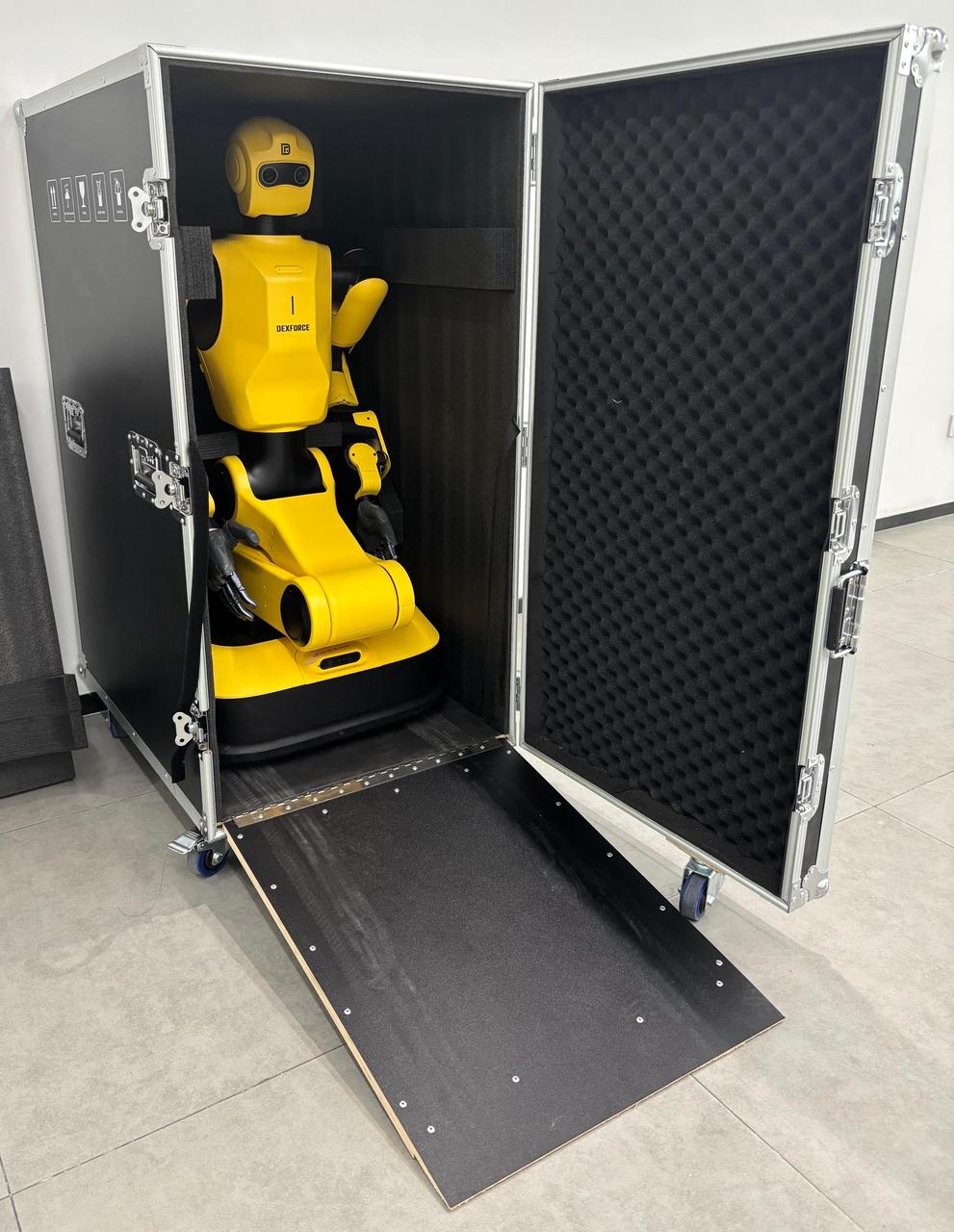
The robot is shipped as a complete unit in a flight case, as shown in the figure below.
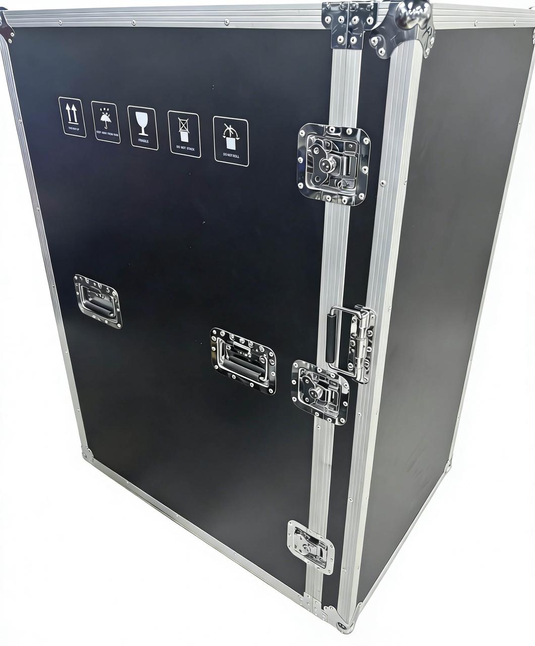
The labels on the outer packaging of the flight case are presented in the table below:
| Label |  |  |  | 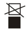 | 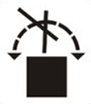 |
|---|---|---|---|---|---|
| Mark | THIS WAY UP | KEEP AWAY FROM RAIN | FRAGILE | DO NOT STACK | DO NOT ROLL |
Follow the steps below to perform the unpacking inspection:
Unpack the robot in an open area. The robot is heavy; therefore, sufficient personnel should assist with the unpacking process to ensure safe handling.
The unpacking procedure is illustrated below:
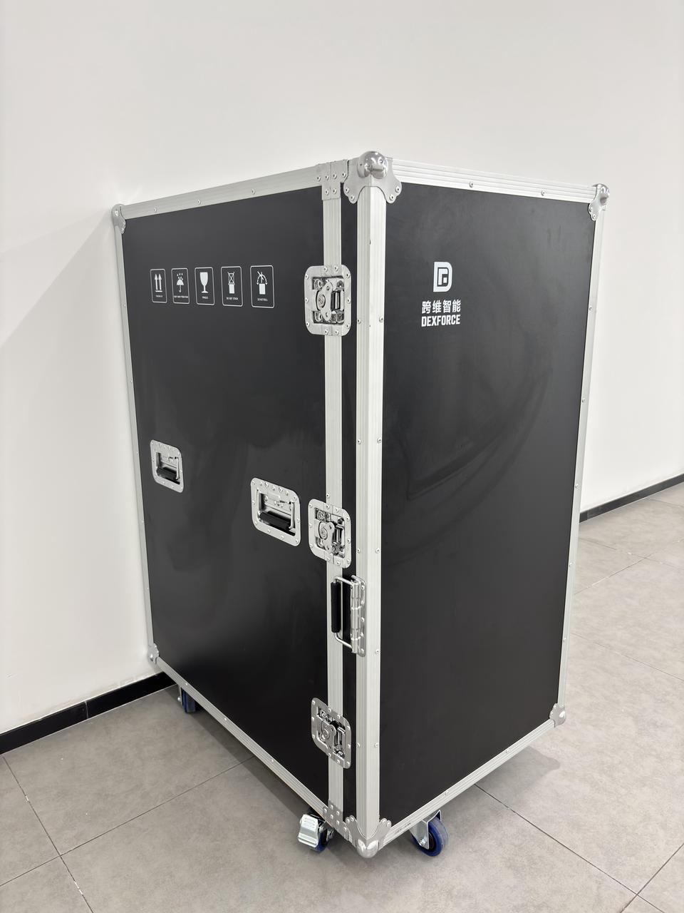
1.Release the foot brake, then unlock the three latches on the side of the flight case.
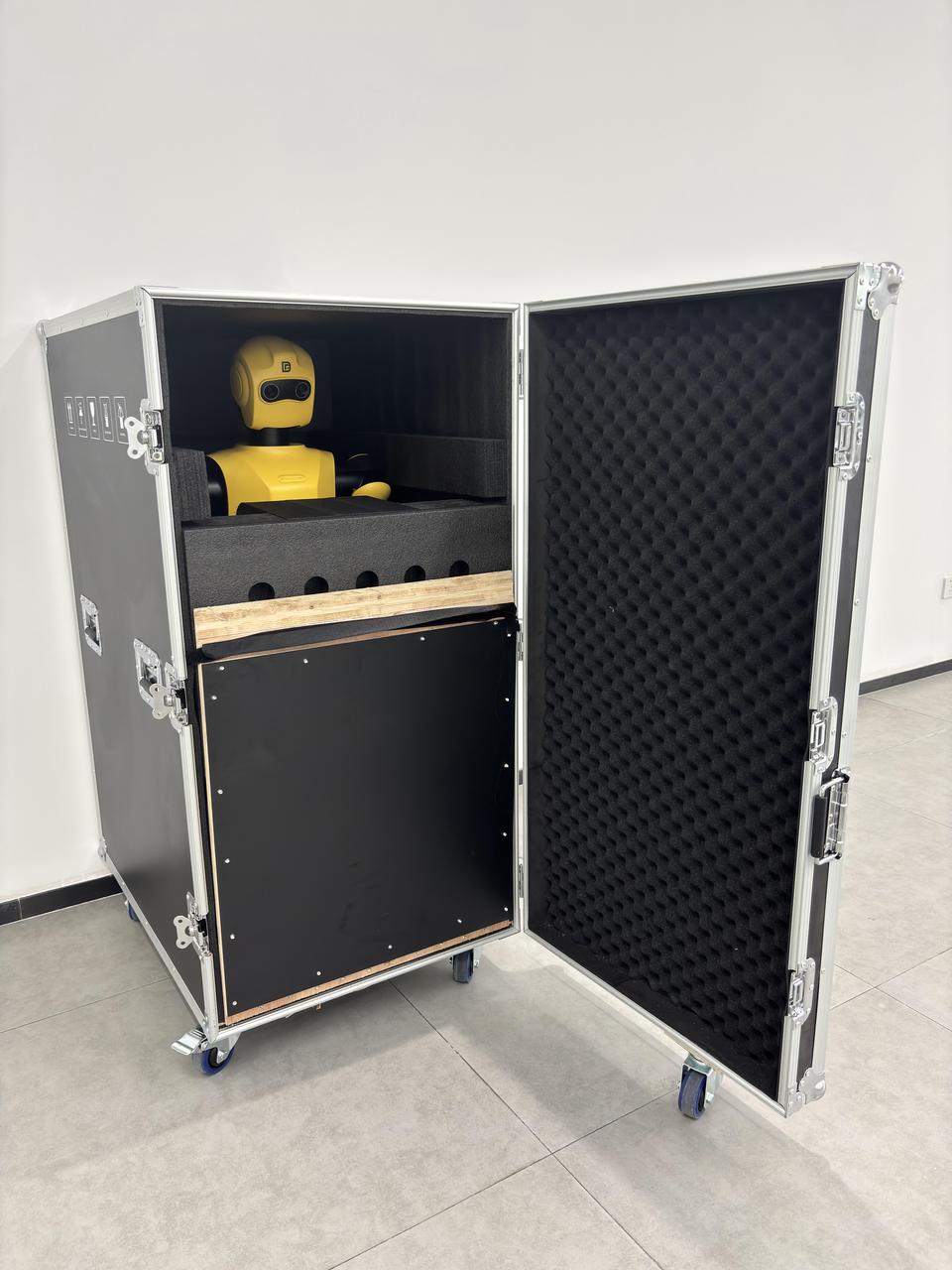
2.Open the side door.
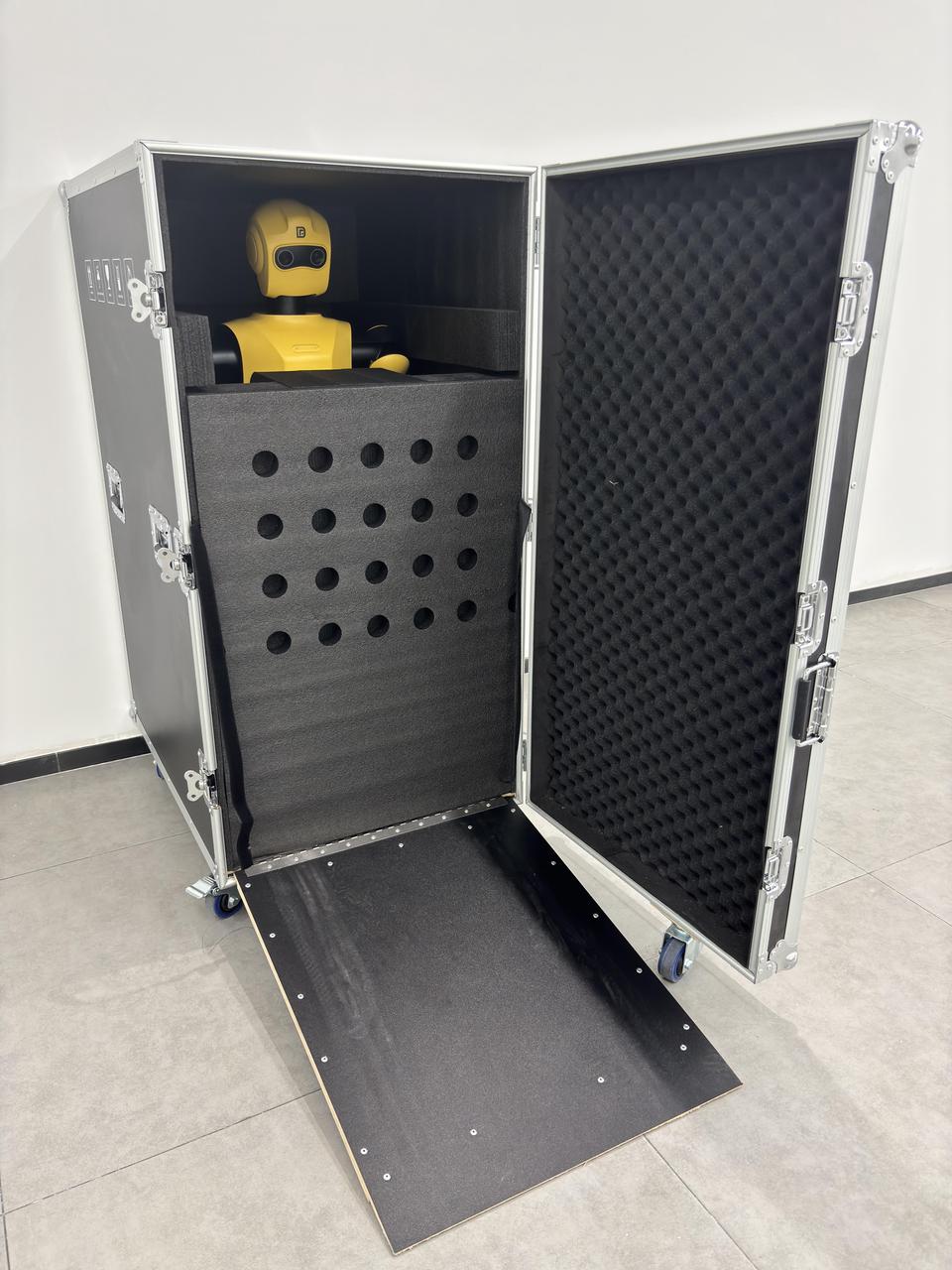
3.Unfasten the securing straps and lower the loading ramp.
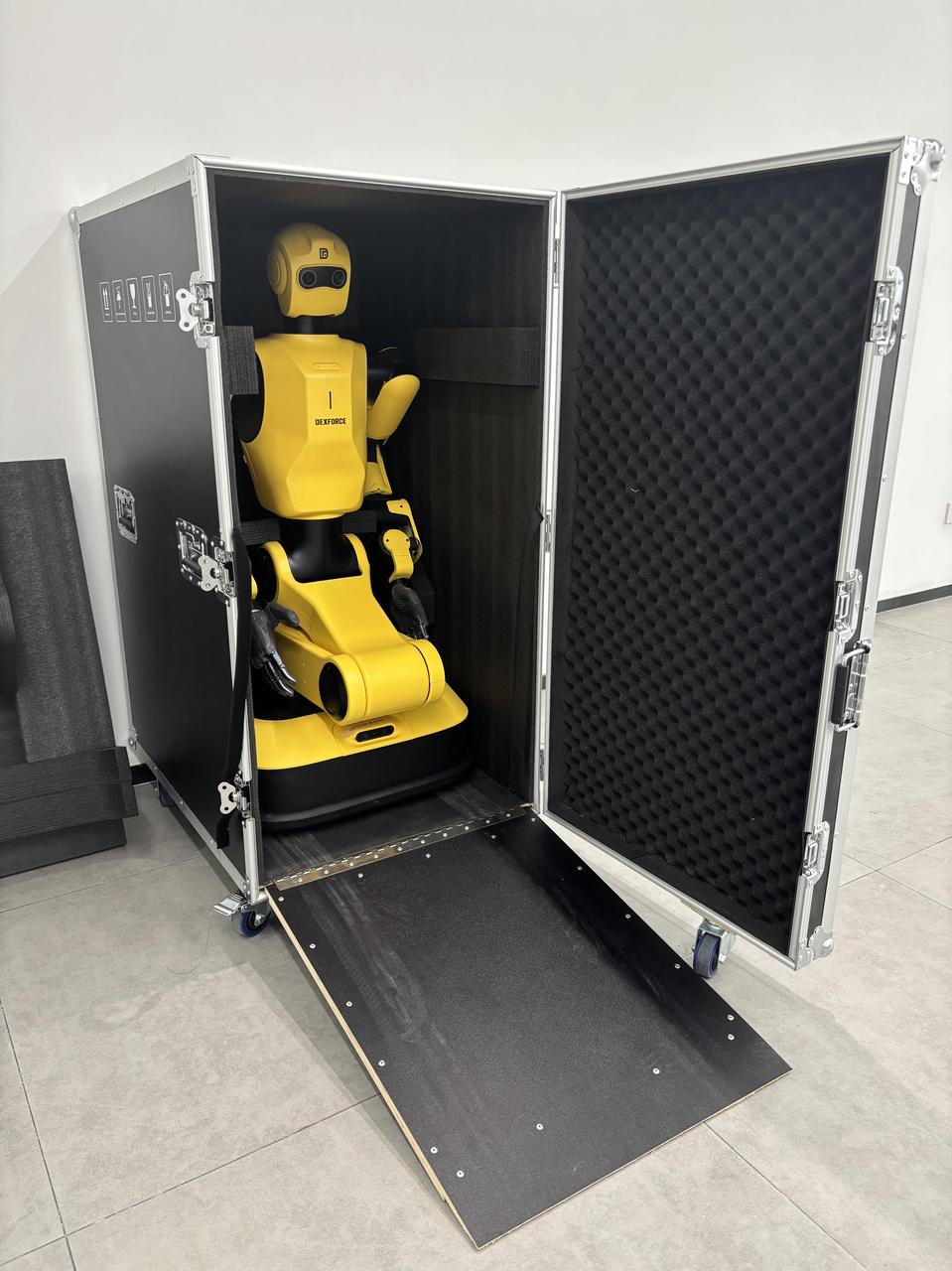
4.Remove the front foam protective padding.
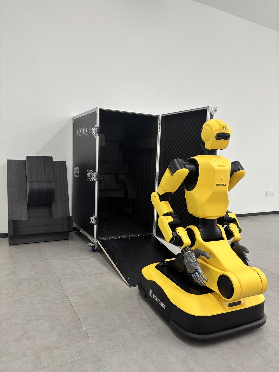
5.Carefully lift the robot out of the flight case.
Verify that all items listed below are present in the flight case:Robot, Product inspection certificate, Product inspection report, Desiccant. After unpacking, retain all packaging materials for future use.
After removing the internal foam and protective film from the flight case, carefully inspect the robot for any signs of transportation-related damage, including cracks or deformation of components. If any abnormalities are observed, please contact Cross-Dimensional Intelligence customer service immediately.
3.1.2 Packing and Transportation
If the robot requires return for repair, please follow the packing and shipping procedure outlined below.
The robot must be packed in a crouched posture. Packing the robot in any other posture will void the warranty.
All original packaging materials should be placed inside the flight case.
When arranging shipment, instruct the logistics carrier that the following conditions must be observed:Avoid strong vibrations, Protect from rain, Keep upright (do not invert), Protect from moisture.
3.2 Power on/off
Note: The robot must remain stationary during the power-on process.
Power Switch
Position the robot in an open area. Ensure that its arms can be fully extended without risk of collision with any obstacles.
Verify that no objects on the chassis are obstructing the LiDAR or RGB-D sensors.
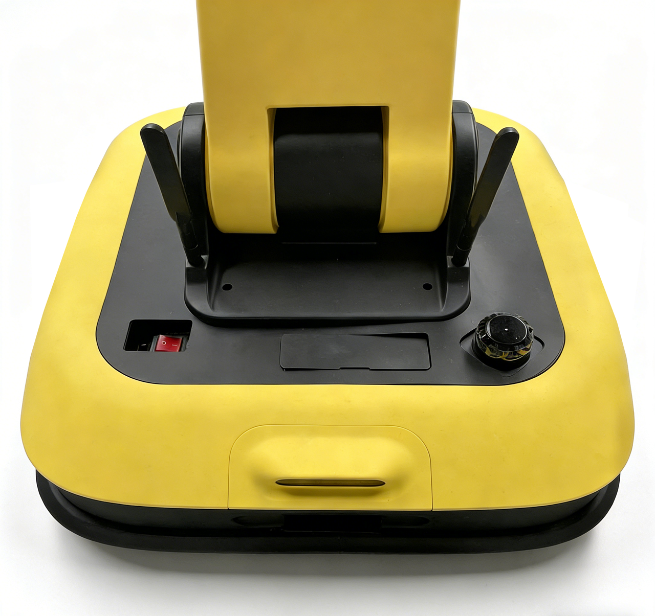
Locate the red rocker switch at the rear left corner of the chassis.
Set the rocker switch to the "I" (On) position to apply power to the entire robot.
The status light: No light → Blue (breathing) → Green steady on (indicates power-on complete).
- PC ON/OFF
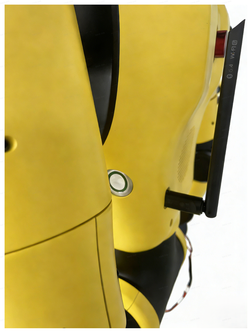
To shut down the robot, press the PC ON/OFF button. The system will complete a soft shutdown within one minute.
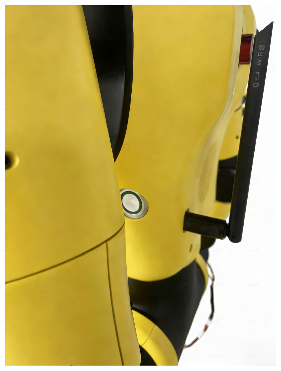
When the robot is in soft shutdown mode (with the power switch still on), press and hold the PC ON/OFF button on the side of the robot's chest for more than three seconds.
The status light: No light → Blue light → Solid green light (indicates that the power-on sequence is complete)
3.3 Standby and Rest
3.3.1 Standby Mode
After the robot has been configured for network access, perform a standby operation to move the robot from its rest mode to the standby mode.
Connect and pair the control handle with PC1. Set the mode switch to D mode and initialize the controller.
Press the Y button with your right hand to switch the robot to standby mode.
Warning:
Other poses can only be switched to after the standby mode has been successfully achieved.
The chassis must remain stationary during standby mode operation. Movement of the chassis is only permitted after the standby mode operation has been completed.
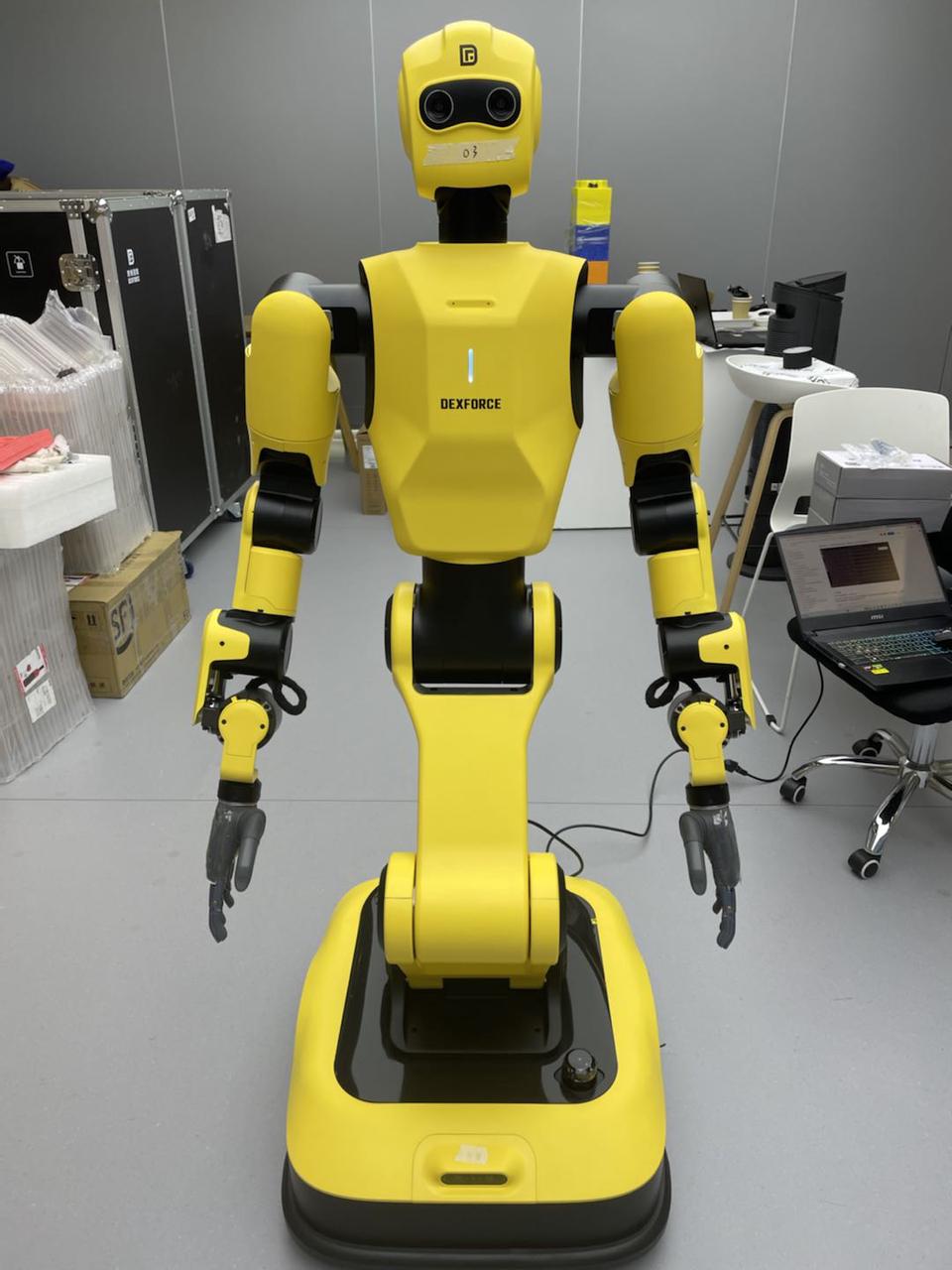
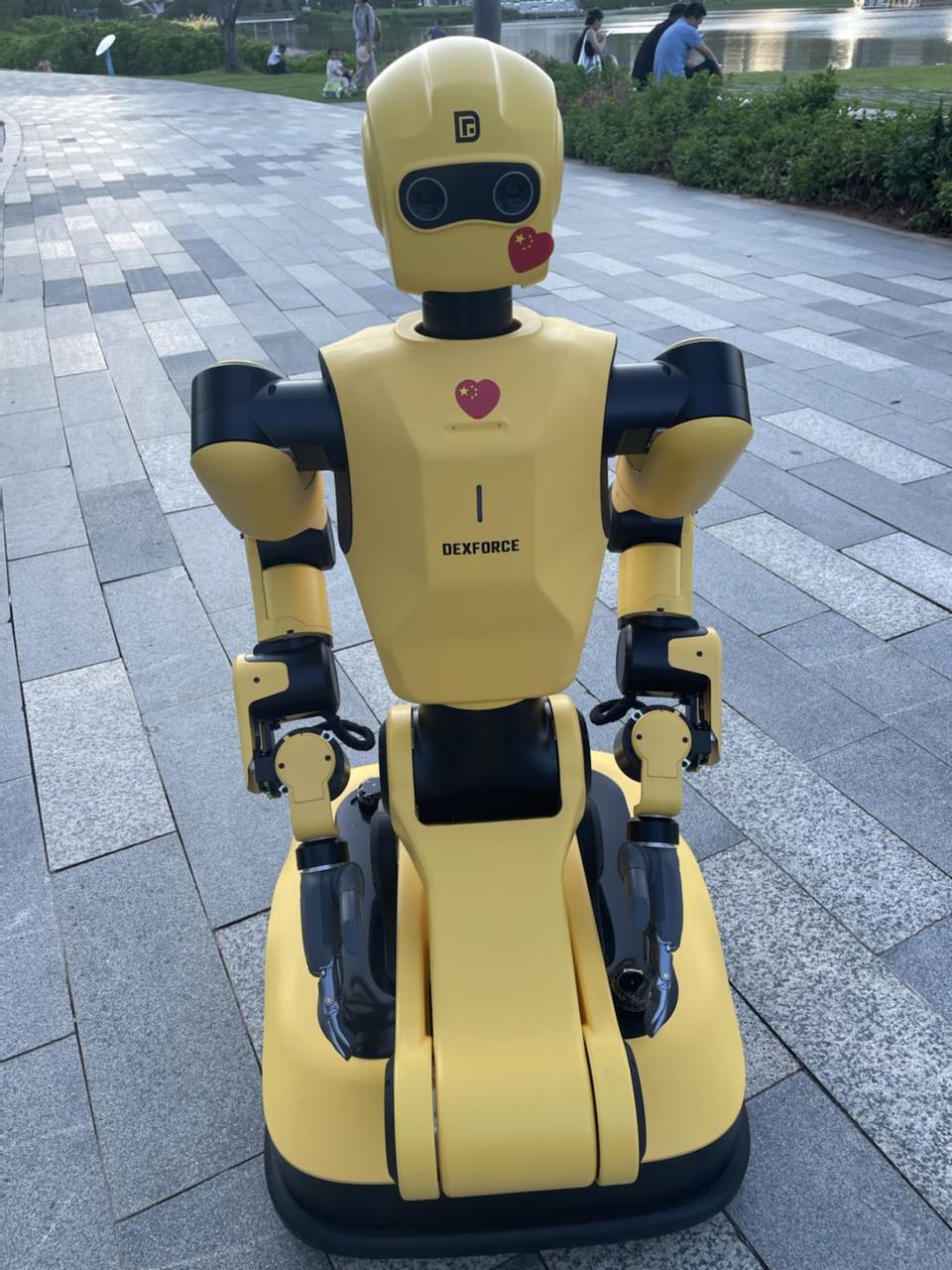
- Once the robot has successfully completed the standby mode operation, its status is as shown in the image below, indicating that unpacking pose initialization is complete and the robot is now in standby mode.
3.3.2 Rest Mode
Ensure the hand is in an upright position. If not, press the Y button with your right hand to return the robot to the standby mode.
Press the A button on the control handle with your right hand to switch the robot to the rest mode.
Warning:
You may only switch to other poses after completing the standby mode or rest mode.
The chassis must remain stationary during standby mode and rest mode operations. Movement is permitted only after both pose operations are completed.
- The robot's status after completing the rest mode operation is shown in the figure below.
3.4 Network Configuration
After power-on, the robot requires network configuration to support remote control, data transmission, and secondary development.
Warning:
PC1 and PC2 are the two onboard computers inside the robot. The commands
sudo apt upgradeandsudo apt-get upgradeare prohibited on both PC1 and PC2, as they may cause system corruption.
3.4.1 Accessing the Onboard PC2
The first is to connect an external display, keyboard, and mouse directly to the onboard PC2 for local access and control. The second is to remotely access and control the onboard PC2 using NoMachine software installed on a personal computer.
3.4.1.1 External display, keyboard, and mouse
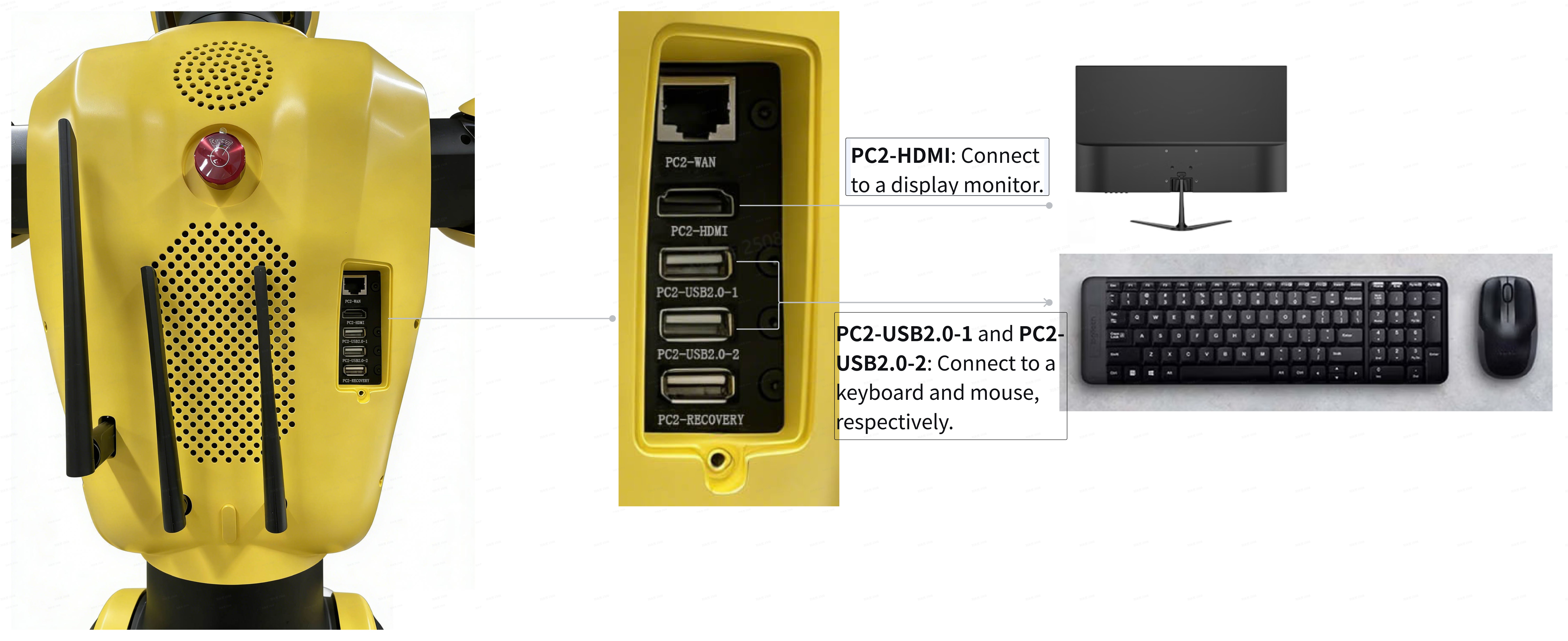
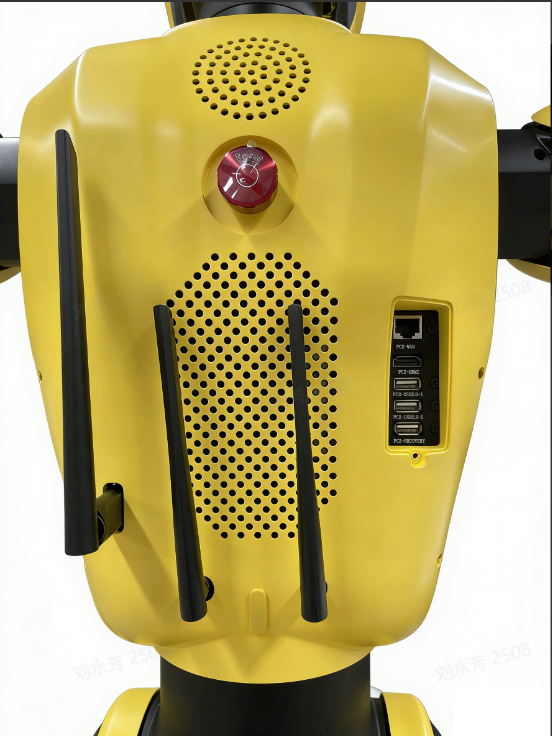
Connect an external display to the PC2-HDMI interface on the robot's back, and connect the keyboard and mouse to the PC2-USB2.0-1 and PC2-USB2.0-2 interfaces, respectively. Once the display shows the PC2 desktop, the onboard PC2 can be connected to the external LAN either via Wi-Fi or through a wired connection.
3.4.1.2 Remote Access to PC2 via NoMachine
3.4.1.2.1 Connecting to the Onboard Switch
① Use an Ethernet cable to connect your personal computer to the LAN port on the robot's chassis.
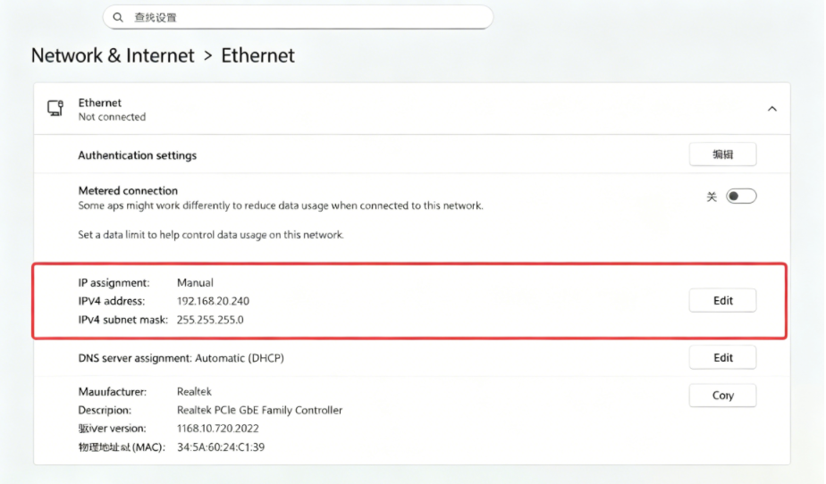
② Set the IP address of your personal computer to any address within the range of 192.168.20.240 to 192.168.20.255 (e.g., 192.168.20.240). This ensures that your personal computer resides on the same subnet as the onboard network, enabling mutual identification and communication.
③ On your personal computer, search for "Terminal" and open it. Then execute the following command to test the connectivity between your personal computer and the onboard network.
④ If the ping is successful, you can then log into PC2 via either SSH or NoMachine remote desktop to establish a control channel to PC2.
3.4.1.2.2 Logging into PC2 via NoMachine
- If you prefer using the command line, you can log into PC2 via SSH by executing the following command in the terminal of your personal computer.
SSH is a secure remote login protocol. This step essentially opens a command-line window on your personal computer that provides control over the robot's onboard PC2.
If you prefer not to use the command line, you can log into PC2 using the NoMachine remote desktop software.
NoMachine allows your personal computer to directly display and operate the full Ubuntu desktop environment of PC2, as if you were using the robot's onboard computer directly.
- Download and install the NoMachine software on your personal computer from the following link:https://www.nomachine.com/
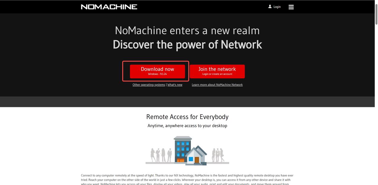
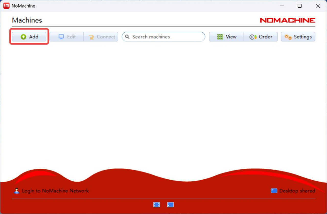
- After downloading and installing the software, open NoMachine and click the
+ Addbutton.
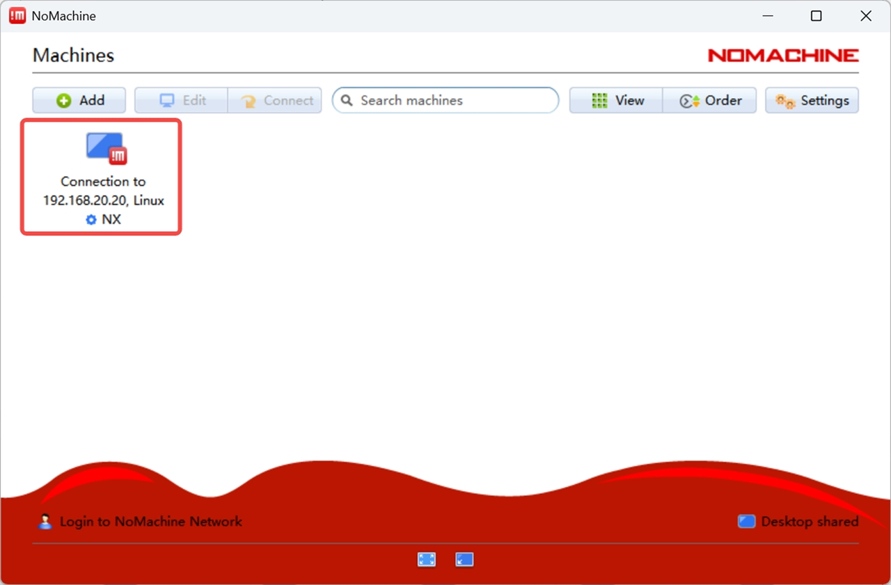
In the Add connection interface, click on Address. Enter "dexforce" in the Name field, and enter the IP address of the onboard computer PC2 in the Host field. Then click the + Add button in the upper‑right corner. Once the connection is successfully established, the interface shown on the right will appear. Click on the corresponding onboard computer to start remote operation.
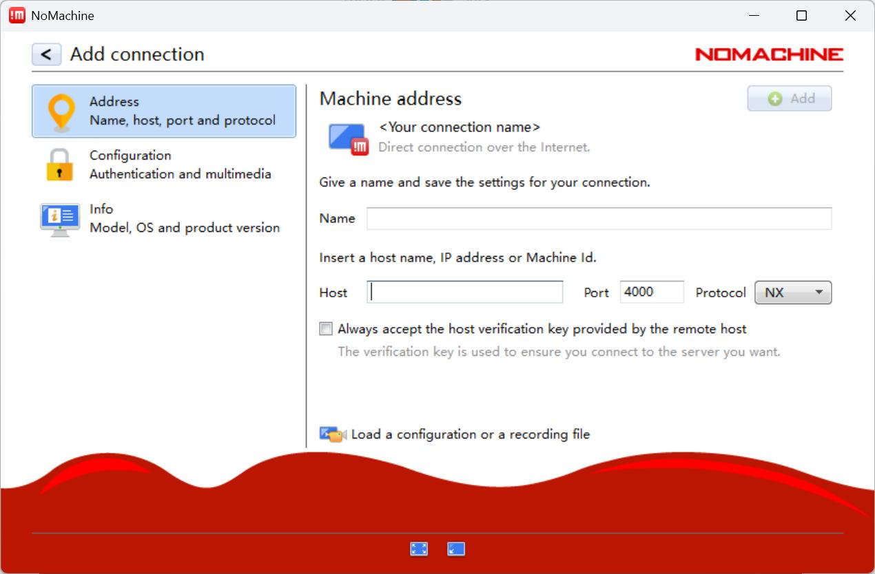
If the robot will subsequently connect to the external LAN via a wired connection, enter "192.168.20.21" (the fixed IP address of PC2) in the Host field.
If the robot will subsequently connect to the external LAN via Wi-Fi, enter the current external IP address of PC2 in the Host field. This address is assigned to PC2 by your local LAN and may change depending on the network to which it is connected.
Note:
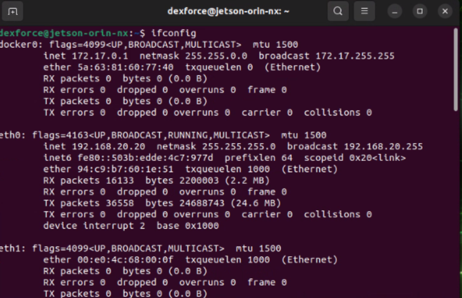
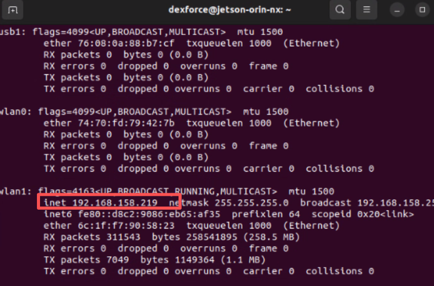
If you do not know this address, you must first refer to Section "Connecting to the Onboard Switch" to connect to the switch. Then, open a terminal on your personal computer, log into PC2 via SSH, and enter the
ifconfigcommand to check the current external IP address of PC2, as shown in the figure below. This IP address is the one you can directly use for future connections.
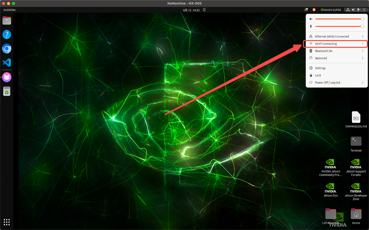
- Once connected, the Ubuntu desktop of PC2 will be displayed on your personal computer screen, as shown in the figure below.
3.4.2 PC2 Access to External Network
3.4.2.1 Connecting to External Network via Wi-Fi
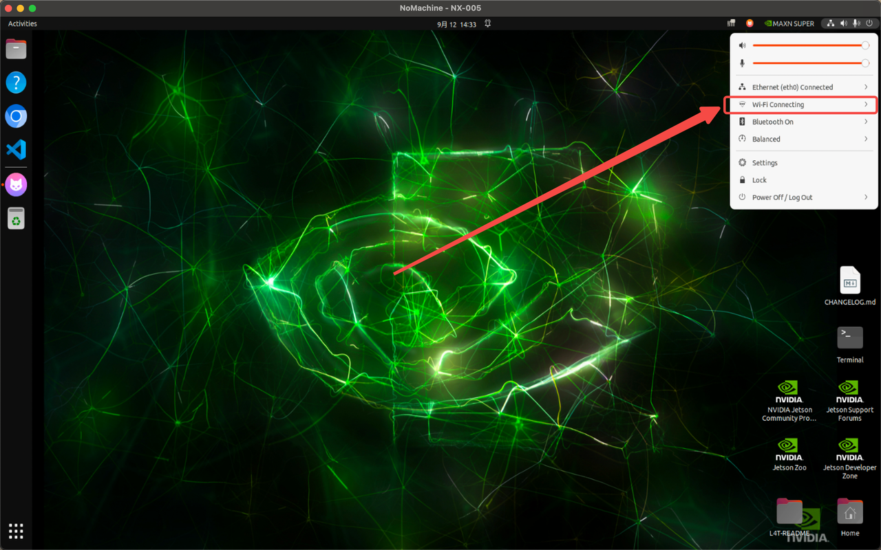
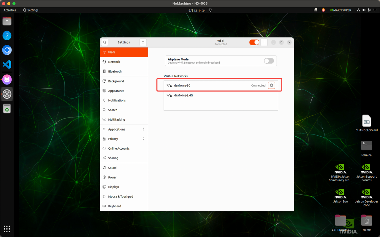
① On the PC2 desktop, locate the network icon in the upper‑right corner of the screen. Left‑click this icon, as shown in the figure below.
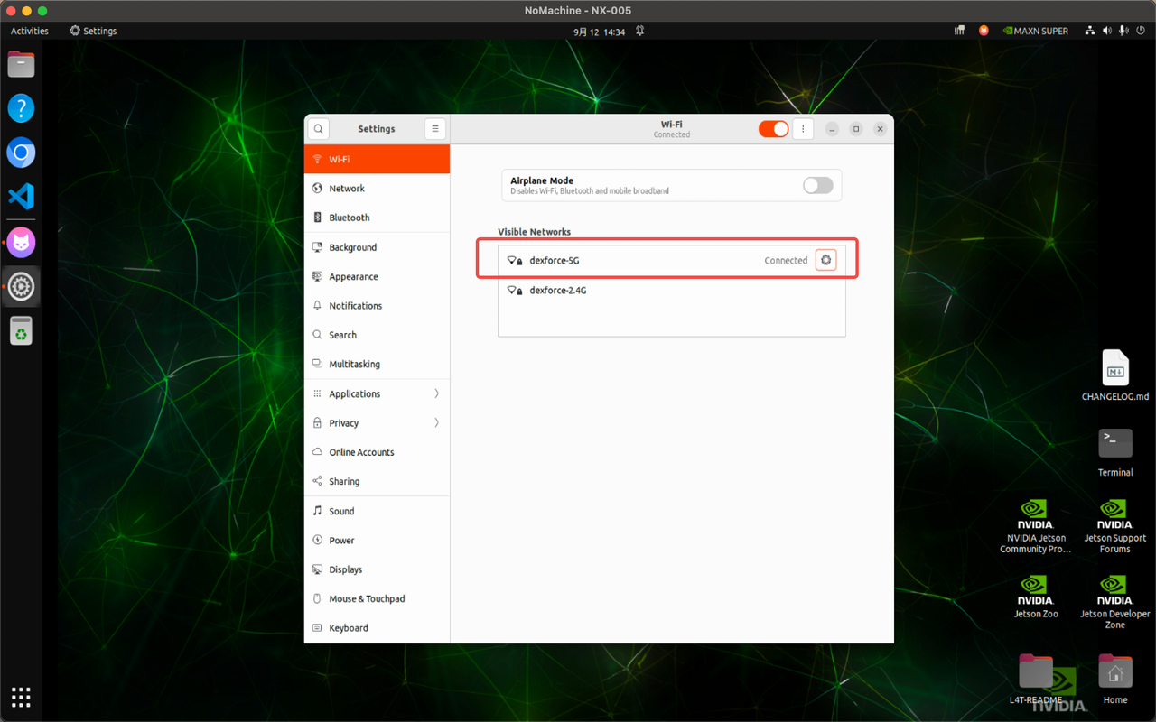
② In the pop-up Wi-Fi list, select the Wi-Fi network you wish to connect to and enter the password to establish the connection.
3.4.2.2 Connecting to External Network via Wired Connection
Warning:
Do not connect a network HUB with Ethernet ports to any PC1 or PC2-related interfaces on the chassis, as this may prevent the onboard computers from starting up properly.
① Locate the PC2-WAN Ethernet port among the interfaces on the robot's back.
② Insert an Ethernet cable that provides internet access into this port. The network settings for this port are configured to automatic (DHCP) by default. Therefore, once the cable is connected, PC2 will automatically recognize and connect to the network (DHCP mode) without requiring any further action.
3.4.3 External Devices Connecting to Hotspot
The robot is equipped with a built‑in Industrial Wi‑Fi AP device. Personal computers or VR devices need to connect to the Wi‑Fi network: Smart_wifi_5G_0xx (where "xx" is the robot's identification number, located on the rear of the chassis). The password is dexforce123. This ensures that the personal computer or VR device resides on the same network as the robot.
3.5 Manual Charging
When the status light strip on the robot flashes yellow slowly, the battery level is below 30%, indicating that charging is required.
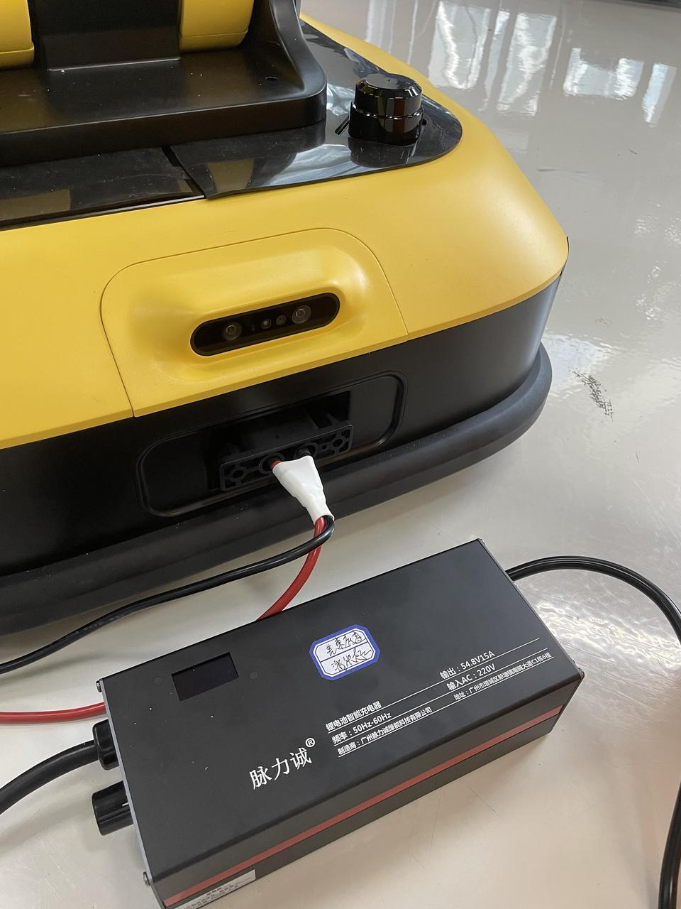
As shown in the figure, insert the charger plug into the port at the rear of the chassis.
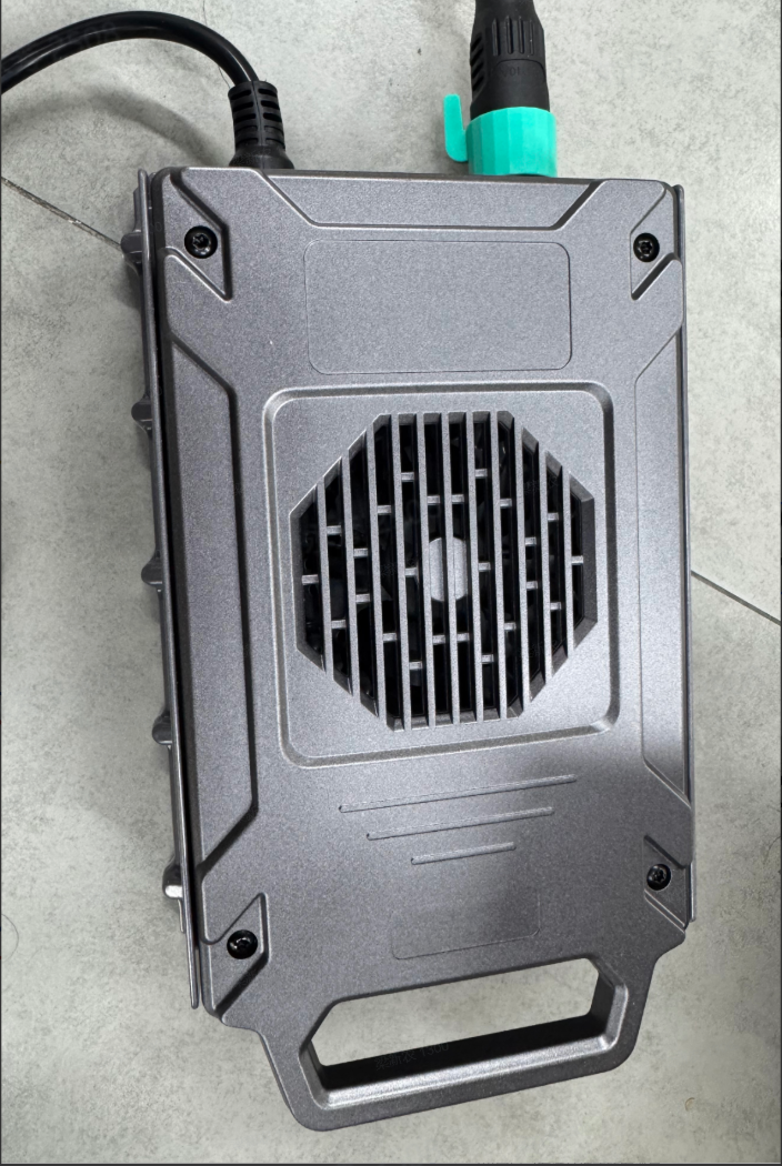
The charging status is illustrated in the figure. On the adapter display, a voltage reading of 54V indicates a full charge, while a reading below 40V indicates insufficient battery power, requiring timely charging.
Note:
Disconnect the charger before the voltage reaches 54V to prevent abnormal motor operation.
3.6 Emergency Stop Button
- In emergency situations, such as when the robot is about to fall, collide, or experience motor runaway, an emergency stop (E-Stop) must be performed. The emergency stop button is the red button located on the back of the robot.
The emergency stop button has two states: pressed and released. Press the button once to enter the pressed state, at which point the emergency stop takes effect. To release, rotate the button to the right (clockwise); it will return to the released state, restoring power and allowing normal operation to resume.
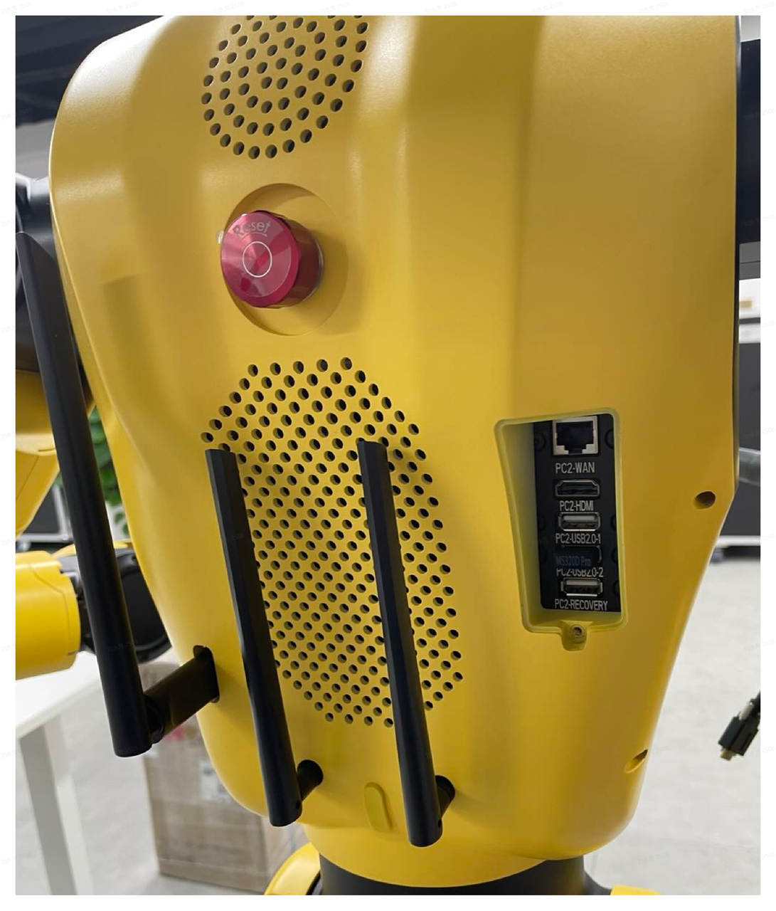
- When the robot enters the emergency stop state by pressing the emergency stop button, release the emergency stop button (rotate it clockwise) and press the PC ON/OFF button once. This will clear the emergency stop status signal, complete the reset operation, and restore the system to normal standby mode.
If the status light on the front of the robot's chest shows a steady green light, it indicates that the emergency stop status has been successfully cleared and the reset is complete. If the status light shows a slow flashing green light, it indicates that the system is in a pending reset state.
3.7 Action Performance
Cross-Dimensional Intelligence has pre-programmed a set of fixed actions for the robot, such as "Heart Gesture," "Salute," etc. By executing simple commands to run these pre-programmed action routines, the robot can perform the corresponding actions and poses.
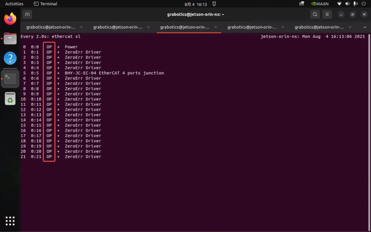
① On the remote desktop of PC1, enter the following command line. Upon successful startup, the display should appear as shown in the figure below. If the display matches the figure and an audible beep is heard, it indicates that dexe_mobile_application has started successfully. All ethercat sl entries should show "op".
② Then, enter the following command line to run the pre‑programmed script.

③ Upon successful startup, the interface should appear as shown in the figure below. It contains seven pre‑programmed actions, with the lower‑right corner displaying the blended effect of all actions.
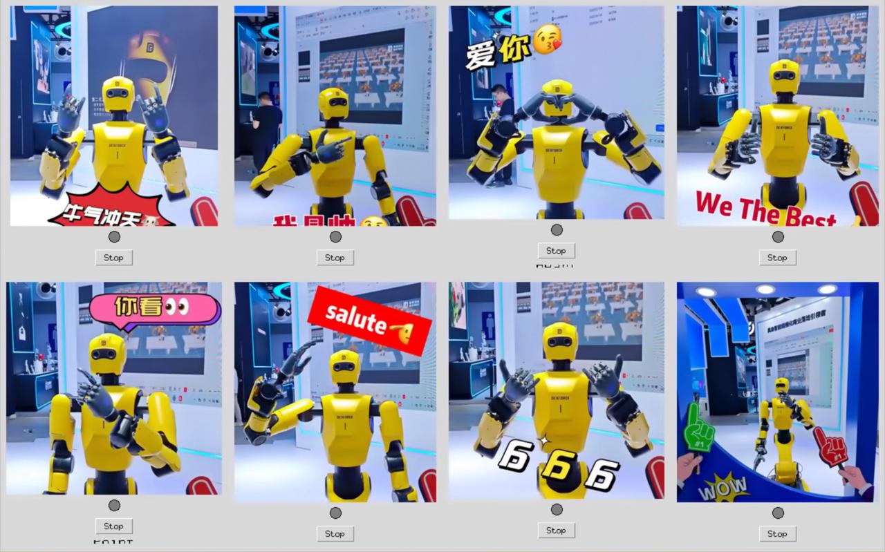
④ During operation, click the corresponding image to execute the action, which will play in a loop. The indicator light below will turn green, indicating that the action is running.
⑤ To switch to a different pre‑programmed action, wait until the current action has completed one full cycle. Then, either click the image of the current action again or click the Stop button at the bottom to halt the action. Once the indicator light turns gray, you may click the next desired action.
⑥ To exit the pre‑programmed script, manually press the ESC key on your personal computer.
3.8 Performing Greeting
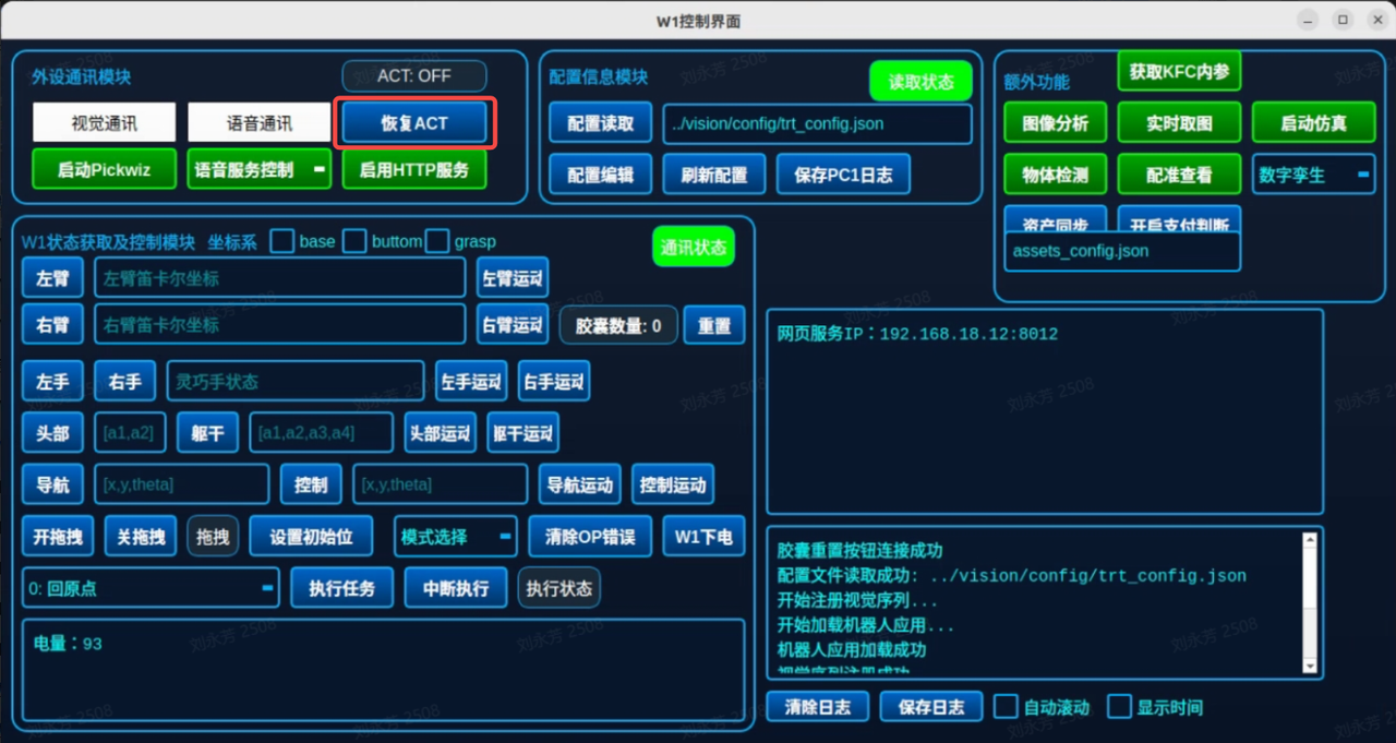
In the W1 Control Interface, click the 【Restore ACT】 button to enable the robot to autonomously perform greetings. To stop the greeting actions, click the 【ACT: OFF】 button. For an introduction to the W1 Control Interface, please refer to the W1 Control Interface section.
3.9 Control Handle
3.9.1 Button Functions
| Button | Functions |
|---|---|
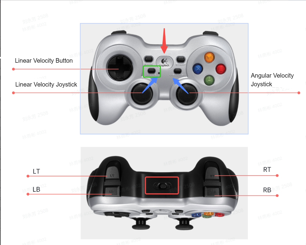
| Logo Button | Used to establish a connection with the receiver. Press to initiate the pairing process.
|
| Mode Button (green box) |
|
| Mode Switch (red box in the figure above) | Must be set to D mode; otherwise, the handle will not function properly. |
| LT/RB | No independent function; must be used in combination with other buttons. |
| LB | Speed switch: When held down, increases the robot's maximum speed to 0.6 m/s (linear velocity) and 1.0 rad/s (angular velocity). |
| RB | Enable button: Must be held down to trigger motion control commands for the robot. |
| Y Button | Triggers the robot's standby pose control: Executes the standard home position action, used to make the robot stand up after being removed from its shipping case. |
| A Button | Triggers the robot's rest pose control: Executes the crouching action for packing and shipping (ensure the hand is upright first). |
| X Button | Triggers Playback Action 1: Executes the BULLS action (loops 3 times; can be operated after returning to the standby pose). |
| B Button | Triggers Playback Action 2: Executes the GUNS action (loops 2 times; can be operated after returning to the standby pose). |
| Linear Velocity Joystick | Controls the robot's linear velocity (push forward = move forward, pull backward = move backward; if the differential drive robot veers, it stops). |
| Angular Velocity Joystick | Controls the robot's angular velocity (push right = clockwise rotation, push left = counterclockwise rotation; if veered left/right, it stops). |
| Linear Velocity Buttons | Single-axis robot motion control: forward = move forward, backward = move backward, left = rotate left, right = rotate right. |
3.9.2 Basic Operations
Basic operations refer to the three core procedures of connecting and pairing the handle with the robot, mode switching, and handle initialization. These operations are prerequisites for all subsequent control commands to take effect.
| Operation Type | Robot Type | Procedure |
|---|---|---|
| Connection & Pairing | Differential Drive | Insert the Logitech receiver into the PC1-USB2.0 port located at the rear of the robot's chassis. Press the Logo button and then the Mode button. When the indicator light next to the Mode button remains steadily on, the connection has been successfully established. |
| Mode Switching | Press the Mode button to switch to "Joystick Stepless Mode" (ensure the indicator light remains off). This prevents abnormal joystick output that could cause the robot to malfunction. At the same time, set the mode switch (red box in the figure above) to D mode to ensure the handle is in a functional state. | |
| Handle Initialization | Simultaneously press and hold both the left and right joysticks, pushing them diagonally upward and inward (as indicated by the blue arrows) to complete handle initialization, thereby ensuring the accuracy of subsequent control commands. |
Note:
When using the handle, the indicator light next to the Mode button must remain off after the connection is confirmed. Otherwise, the left joystick will only output minimum and maximum values, causing the robot not to move.
3.9.3 Chassis Movement Operation
Chassis movement operation refers to the actions of sending linear velocity and angular velocity commands to the robot via handle buttons and joysticks to achieve displacement motions such as translation, rotation, and curved movement. These operations must follow the rule of "enable first, then control" (press and hold the RB button to keep the enable state active).
Note:
All motion control commands require the RB button to be pressed and held to maintain the enable state. In default mode, the robot's maximum linear velocity is 0.4 m/s, and the maximum angular velocity is 0.75 rad/s.
If high-speed motion is required, additionally press and hold the LB button. The robot's maximum linear velocity will then be adjusted to 0.6 m/s, and the maximum angular velocity to 1.0 rad/s.
| Operation Type | Robot Type | Operation Procedure |
|---|---|---|
| Fine Control – Forward / Backward | Differential Drive | Press and hold the RB button with your right hand. Operate the linear velocity joystick with your left hand: push forward = move forward, pull backward = move backward. Differential drive robot: Joystick veers forward/backward → motion stops. |
| Single-Axis Control – Forward / Backward | Press and hold the RB button with your right hand. Operate the linear velocity buttons with your left hand: forward = move forward, backward = move backward. | |
| Fine Control – Rotation | Press and hold the RB button with your right hand. Operate the angular velocity joystick with your right thumb: push right = clockwise rotation, push left = counterclockwise rotation. Veering left/right → rotation stops. | |
| Fine Control – Curved Movement | Press and hold the RB button with your right hand. Operate the linear velocity joystick with your left hand and the angular velocity joystick with your right thumb: - Push forward + push right → curve forward to the right; - Push forward + push left → curve forward to the left; - Pull backward + push right → curve backward to the right; - Pull backward + push left → curve backward to the left. |
3.9.4 Pose Control Operation
Pose control operation refers to the actions of triggering the robot to execute predefined poses (standby pose, rest pose) or specified actions via handle buttons. This is a critical operation for the robot to complete task-specific scenarios.
Note:
During pose control operations, movement operations are not permitted. Similarly, pose control operations should not be triggered during movement operations to avoid mechanical structure conflicts.
While the robot is performing standby pose or rest pose operations, chassis movement is prohibited. Chassis movement is allowed only after the standby pose or rest pose has been fully achieved.
During chassis movement, executing standby pose or rest pose operations is not permitted.
| Operation Type | Robot Type | Operation Procedure | Precautions |
|---|---|---|---|
| Standby Pose Control | Differential Drive | Press the Y button with your right hand. | Used to make the robot stand up after being removed from the shipping case. Switching to other poses is only allowed after this pose operation is complete. |
| Rest Pose Control | Press the A button with your right hand. | Used to make the robot crouch for packing. Switching to other poses is only allowed after this pose operation is complete. Note: Before executing the rest pose, ensure that the hand is in an upright position; otherwise, the waist may collide with the hand when crouching. | |
| Action 1 | Press the X button with your right hand. | The robot performs the BULLS action three times. Other operations can only be performed after returning to the standby pose. | |
| Action 2 | Press the B button with your right hand. | The robot performs the GUNS action twice. Other operations can only be performed after returning to the standby pose. |