Hardware Introduction
2.1 Product Composition
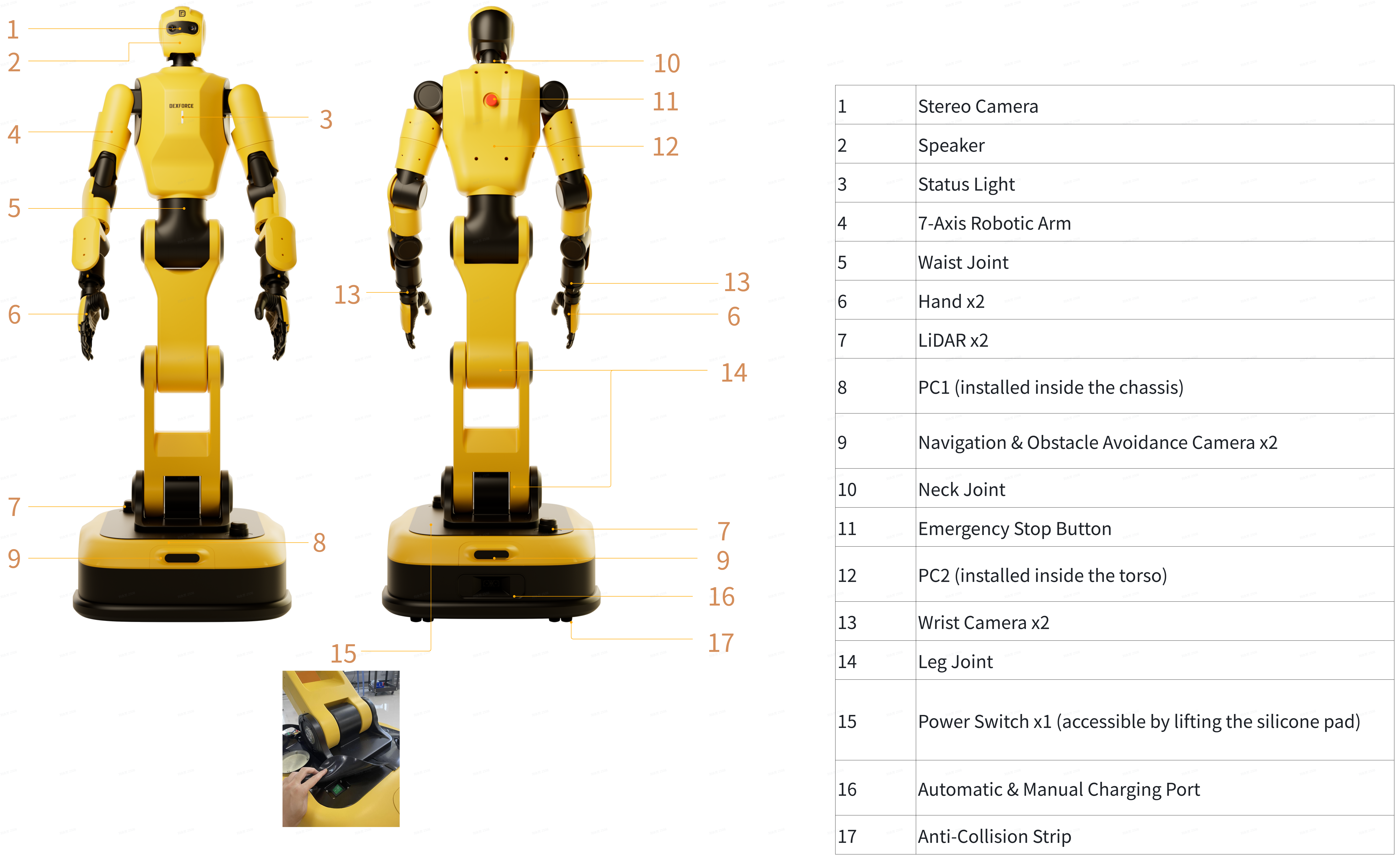
2.2 Audio-visual interaction
Robot audio-visual interaction refers to a mechanism in which the robot utilizes status lights (light signals) to communicate its operating status, operational prompts, and safety alerts to the user. The status light located on the front of the robot's chest serves as the primary output channel for light signals. As the robot transitions into a given state, it simultaneously activates a corresponding status light color and flashing pattern.
Color
Red: Indicates a malfunction that requires immediate intervention.
Yellow: Indicates a notification or advisory status.
Blue: Indicates a waiting state.
Green: Indicates normal operating condition.
Robot Status List
| state | Status Description | Lighting display |
|---|---|---|
| Emergency Stop | Emergency stop condition persists and has not been resolved. The anti-collision strip has been triggered beyond the allowed duration. | Red (steady) |
| Low Battery | Battery level has fallen to the software-defined low battery threshold. | Yellow (flashing) |
| Charging | Robot is executing an automatic or manual charging task. | Green (breathing) |
| Powering On | Robot is powered on via PC ON/OFF button or power switch. PC is performing system initialization. | Blue (breathing) |
| Standby | Power-on sequence is complete; robot is ready in standby mode. | Green (steady) |
| Pending Reset | The system is in a reset state. Press the PC ON/OFF button once to complete the reset. | Green (slow flashing) |
| Soft Shutdown in Progress | The robot has activated the PC ON/OFF button, issued a voice prompt, and is initiating system shutdown. | White (flashing) |
2.3 External Interface
External Interfaces (HW V0.23 Versions)

| Interface Area | Interface | Function |
|---|---|---|
| Back | Emergency Stop Button | Cuts power to the robot's motors during emergencies (e.g., imminent fall, collision, or motor runaway), quickly halting movement to prevent accidents. |
| PC2-WAN | Standard Wired Network Interface – Connects PC2 to an external network for external communication. | |
| PC2-HDMI | HDMI Output – Connects to external displays for video output. | |
| PC2-USB2.0-1 | USB 2.0 Host – For connecting user peripherals (e.g., keyboard or mouse). | |
| PC2-USB2.0-2 | USB 2.0 Host – For connecting user peripherals (e.g., keyboard or mouse). | |
| PC2-RECOVERY | Restricted to Cross-Dimensional Intelligence technical support personnel for PC2 software image upgrades. | |
| Left Thorax | PC ON/OFF | A button for software-controlled power on/off. Initiates orderly PC shutdown. When the robot is in emergency stop mode, releasing the E-Stop button and pressing this button clears the emergency stop signal and completes reset. |
| Front of the Chassis | PC1-USB3.0 | USB 3.0 Host port for connecting user peripherals (e.g., keyboard, mouse). |
| PC1-RECOVERY | Restricted to Cross-Dimensional Intelligence technical support personnel for PC1 software image upgrades. | |
| Rear of the Chassis | Power Switch | A rocker switch used to turn the robot on or off at the hardware level. Activate it during initial power-on.
|
| PC1-WAN | Standard wired network interface for connecting PC1 to an external network. | |
| LAN | Standard wired network interface for connecting a personal computer to the robot's internal network. | |
| PC1-USB2.0 | Enables connection of an external remote control handle for robot movement control. A USB expansion dock may also be connected to add additional peripheral devices to PC1. | |
| EXTERNAL ESTOP | Connects to the signal contacts of a remote emergency stop head to enable remote emergency stop signal reception. Note: A standard emergency stop button cannot be wired in series within this circuit. |
External Interfaces (HW V0.24 Versions)
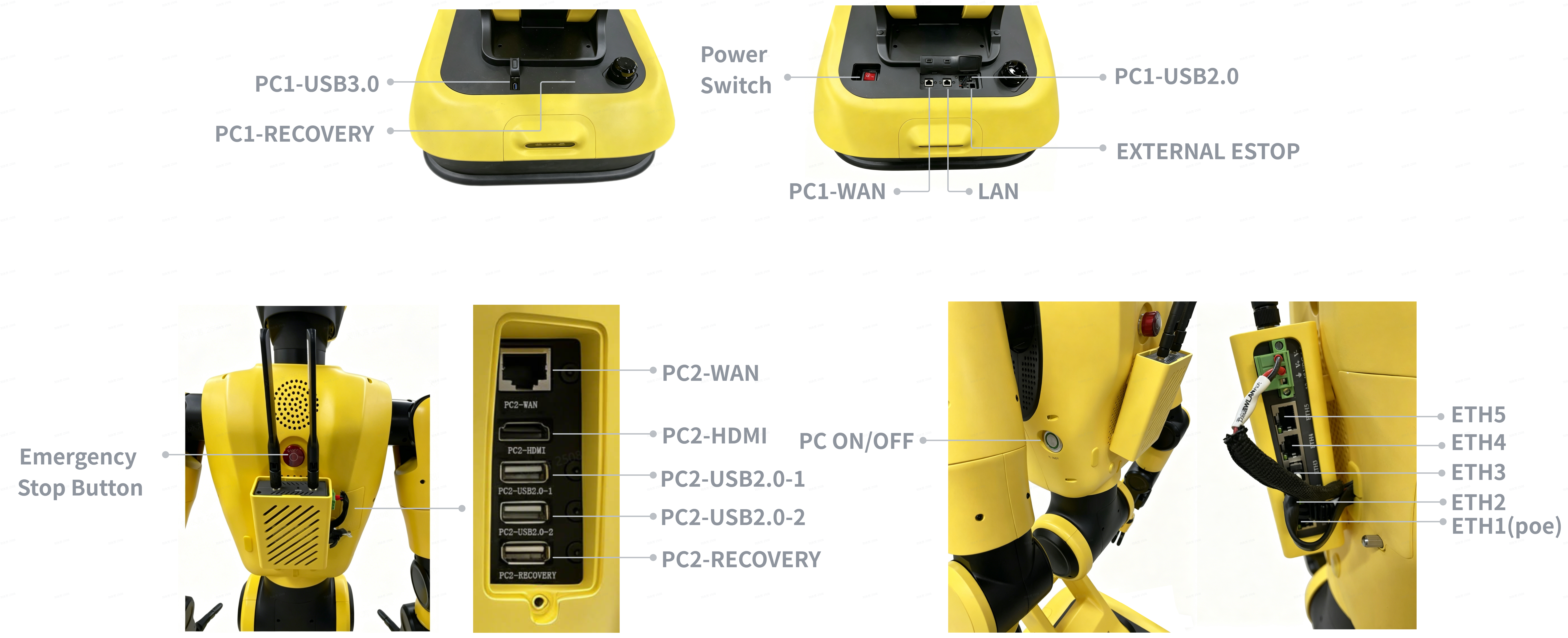
| Interface Area | Interface | Function |
|---|---|---|
| Back | Emergency Stop Button | Cuts power to the robot's motors during emergencies (e.g., imminent fall, collision, or motor runaway), quickly halting movement to prevent accidents. |
| PC2-WAN | Standard Wired Network Interface – Connects PC2 to an external network for external communication. | |
| PC2-HDMI | HDMI Output – Connects to external displays for video output. | |
| PC2-USB2.0-1 | USB 2.0 Host – For connecting user peripherals (e.g., keyboard or mouse). | |
| PC2-USB2.0-2 | USB 2.0 Host – For connecting user peripherals (e.g., keyboard or mouse). | |
| PC2-RECOVERY | Restricted to Cross-Dimensional Intelligence technical support personnel for PC2 software image upgrades. | |
| Left Thorax | PC ON/OFF | A button for software-controlled power on/off. Initiates orderly PC shutdown. When the robot is in emergency stop mode, releasing the E-Stop button and pressing this button clears the emergency stop signal and completes reset. |
| Industrial AP | Industrial AP ETH1 (PoE) | Standard RJ45 port. Currently not supported. |
| Industrial AP ETH2 | Standard RJ45 port. Connects to a switch for uplink to an external LAN. | |
| Industrial AP ETH3 | Standard RJ45 port. Connects to PC2. | |
| Industrial AP ETH4 | Standard RJ45 port. Currently not supported. | |
| Industrial AP ETH5 | Standard RJ45 port. Currently not supported. | |
| Front of the Chassis | PC1-USB3.0 | USB 3.0 Host port for connecting user peripherals (e.g., keyboard, mouse). |
| PC1-RECOVERY | Restricted to Cross-Dimensional Intelligence technical support personnel for PC1 software image upgrades. | |
| Rear of the Chassis | Power Switch | A rocker switch used to turn the robot on or off at the hardware level. Activate it during initial power-on.
|
| PC1-WAN | Standard wired network interface for connecting PC1 to an external network. | |
| LAN | Standard wired network interface for connecting a personal computer to the robot's internal network. | |
| PC1-USB2.0 | Enables connection of an external remote control handle for robot movement control. A USB expansion dock may also be connected to add additional peripheral devices to PC1. | |
| EXTERNAL ESTOP | Connects to the signal contacts of a remote emergency stop head to enable remote emergency stop signal reception. Note: A standard emergency stop button cannot be wired in series within this circuit. |
2.4 Joint Motor Specifications
The W1 Pro robot consists of a head, neck, waist, legs, arms, and robotic hands, featuring 24 or 34 degrees of freedom throughout its body. This design enables flexible motion and high-precision attitude control.
| Joint DOF | W1 Pro Robot (Gripper) | W1 Pro Robot (Hand) |
|---|---|---|
| Total | 24 | 34 |
| Neck | 2(NECK1, NECK2) | 2(NECK1, NECK2) |
| Arm(Single) | 7 (Shoulder: 3, Elbow: 1, Wrist: 3) | 7 (Shoulder: 3, Elbow: 1, Wrist: 3) |
| End Effector | 1 | 6 |
| Waist | 2(WAIST, BUTTOCK) | 2(WAIST, BUTTOCK) |
| Leg | 2 (KNEE, ANKLE) | 2 (KNEE, ANKLE) |
| Chassis | 2 | 2 |
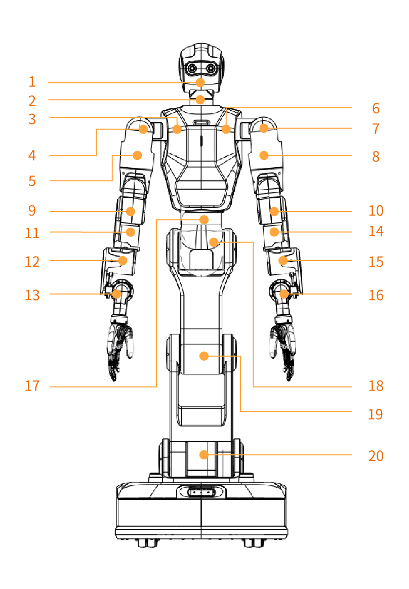
| Joint No. | Joint Name | Limit (°) | Speed (°/s) | Remark | ||
|---|---|---|---|---|---|---|
| Max (°) | Min (°) | |||||
| 1 | NECK1 | 25 | -45 | 50deg/s | ||
| 2 | NECK2 | 90 | -90 | 50deg/s | ||
| 3 | RIGHT_J1 | 170 | -170 | 50deg/s | ||
| 4 | RIGHT_J2 | 90 | -120 | 50deg/s | ||
| 5 | RIGHT_J3 | 170 | -170 | 50deg/s | ||
| 6 | LEFT_J1 | 170 | -170 | 50deg/s | ||
| 7 | LEFT_J2 | 90 | -120 | 50deg/s | ||
| 8 | LEFT_J3 | 170 | -170 | 50deg/s | ||
| 9 | RIGHT_J4 | 135 | -90 | 50deg/s | ||
| 10 | LEFT_J4 | 135 | -90 | 50deg/s | ||
| 11 | RIGHT_J5 | 170 | -170 | 50deg/s | ||
| 12 | RIGHT_J6 | 45 | -45 | 50deg/s | ||
| 13 | RIGHT_J7 | 60 | -90 | 50deg/s | ||
| 14 | LEFT_J5 | 170 | -170 | 50deg/s | ||
| 15 | LEFT_J6 | 45 | -45 | 50deg/s | ||
| 16 | LEFT_J7 | 60 | -90 | 50deg/s | ||
| 17 | WAIST | HW V0.23 | 170 | -170 | 75deg/s | Left:+ Right: - |
| HW V0.24 | 125 | -215 | 75deg/s | Left:+ Right: - | ||
| 18 | BUTTOCK | 90 | -110 | 50deg/s | Backward bend: + Forward bend: - | |
| 19 | KNEE | 155 | -155 | 75deg/s | Forward: + Backward:- | |
| 20 | ANKLE | 90 | -90 | 50deg/s | Forward: + Backward:- |